1
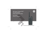
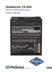
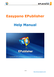
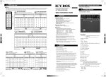
Network Video Recorder
User Manual
1.0.0.22
Product name:
Network Video Recorder
Release Date:
2015/05
Manual Revision:
V1.0
Web site:
www.brickcom.com
Email:
[email protected]
[email protected]
Information in this document is subject to change without notice.
© Copyright 2015. All rights reserved.
Table of Contents
Chapter 1.
1.1
Introduction .............................................................................. 2
Hardware Description ................................................................................. 3
1.1.1
NR-1100 Series ................................................................................. 3
1.1.2
NR-2100 Series ................................................................................. 4
1.1.3
NR-4200 Series ................................................................................. 5
1.1.4
NR-8200-RM Series .......................................................................... 6
1.2
LED Indicators Status.................................................................................... 7
1.2.1
NR-1100 Series ................................................................................. 7
1.2.2
NR-2100 Series ................................................................................. 8
1.2.3
NR-4200 Series ................................................................................. 9
1.2.4
NR-8200-RM Series ........................................................................ 11
1.3
Dual Display Solution: HDMI/VGA/DVI-I Connection ........................... 13
Chapter 2.
NVR Installation ...................................................................... 14
2.1
Remote Web Browser PC System Requirements ................................... 14
2.2
Connect to NVR ......................................................................................... 15
2.2.1
Quick Guide .................................................................................... 15
2.2.2
Install NVR Search ......................................................................... 15
2.2.3
Activate Live View Service ............................................................ 21
2.2.4
Quick configuration ....................................................................... 23
i
Chapter 1.
Introduction
Before You Use This Product
When you first open the product’s package, verify that all the accessories listed on
the “Package Contents” of “Quick Installation Guide” are included. Before installing
the NVR, please read the instructions in the “Quick Installation Guide” to avoid
misuse and then follow the instructions in the “Hard Disk Installation” section to
avoid damages due to faulty assembly or installation.
2
1.1 Hardware Description
1.1.1 NR-1100 Series
Figure 1-1. Front & Rear View of NR-1100 Series
1.
Power button
2.
3.
4.
LED indicators: HDD
USB 2.0 x1 (Support auto video backup)
USB 2.0 x1
5.
6.
7.
8.
Power connector
USB 3.0 x 2
DVI-I
eSATA x 1
9.
10.
11.
12.
HDMI x 1
Gigabit LAN
USB 2.0 x 2
Audio mic input (reserved)
13. Audio output (reserved)
3
1.1.2 NR-2100 Series
Figure 1-4. Front & Rear View of NR-2100 Series
1.
Power button
2.
3.
4.
LED indicators: HDD
USB 2.0 x1 (Support auto video backup)
USB 2.0 x1
5.
6.
7.
8.
Power connector
USB 3.0 x 2
DVI-I
eSATA x 1
9.
10.
11.
12.
HDMI x 1
Gigabit LAN
USB 2.0 x 2
Audio mic input (reserved)
13. Audio output (reserved)
4
1.1.3 NR-4200 Series
Figure 1-5. Front & Rear View of NR-4200 Series
1.
LED indicators: LAN1, LAN2, eSATA, HDD1, HDD2, HDD3, HDD4
2.
3.
4.
Power button
USB BACKUP button - Auto video backup
USB 2.0 x 1(Support auto video backup)
5.
6.
7.
8.
USB 2.0 x 1
HDD1
HDD2
HDD3
9.
10.
11.
12.
HDD4
Gigabit LAN x 2
USB 2.0 x 4
eSATA x 2
13. VGA output
14. HDMI output
15. DI/DO (4 in 2 out)
Top to bottom: Vcc5V, GND, DI-1, DI-2, DI-3, DI-4, DO-1, DO-2
16. Reset button*
17. Power connector
18. K-lock security slot
5
1.1.4 NR-8200-RM Series
Figure 1-8. Front & Rear View of NR-8200-RMSeries
1. LED indicators: LAN1, LAN2, eSATA, HDD1, HDD2, HDD3, HDD4, HDD5, HDD6,
HDD7, HDD8
2. Power button
3. USB BACKUP button - Auto video backup
4. USB 3.0 x 1 (Support auto video backup)
5. HDD1
6.
7.
8.
9.
HDD2
HDD3
HDD4
HDD5
10. HDD6
11. HDD7
12. HDD8
13. Gigabit LAN x 2
14. USB 2.0 x 4
15. eSATA x 2
16. VGA output
17. HDMI output
18. DI/DO (4 in 2 out)
Right to left: Vcc5V, GND, DI-1, DI-2, DI-3, DI-4, DO1, DO2
19. Reset button*
20. Power connector
6
1.2 LED Indicators Status
1.2.1 NR-1100 Series
Figure 2-3. NR-1100 Series Front Panel
Note:
**To turn off your NVR, long pressing power button at least 2 seconds.
**To turn on your NVR, long pressing power button at least 3 seconds.
Note: To reset to default, please follow below methods:
Press the power button twice with the interval of one second. In other words, please
press the power button in the 1st second and press the power button again in the 2nd
second. It will be easier to operate the reset to default with the assistance of watch
or clock.
Note: Once users press reset button, configuration of Camera Setting,
Recording Settings, Event & Action Setting, E-Mail Settings, and Server Settings
will reset to default. It is advised to backup system configurations. For more
information, refer to detail information in user manual 5.6.3 Save/Load
Configuration.
7
1.2.2 NR-2100 Series
Figure 2-4. NR-2100 Series Front Panel
Note:
**To turn off your NVR, long pressing power button at least 2 seconds.
**To turn on your NVR, long pressing power button at least 3 seconds.
Note: To reset to default, please follow below methods:
Press the power button twice with the interval of one second. In other words, please
press the power button in the 1st second and press the power button again in the 2nd
second. It will be easier to operate the reset to default with the assistance of watch
or clock.
Note: Once users press reset button, configuration of Camera Setting, Recording
Settings, Event & Action Setting, E-Mail Settings, and Server Settings will reset to
default. It is advised to backup system configurations. For more information, refer to
detail information in user manual 5.6.3 Save/Load Configuration.
8
1.2.3 NR-4200 Series
Figure 2-5. NR-4200 Series Front Panel & RJ-45 Port
LED on Front Panel
LED
LED Color & Status
Indicate
Off
LAN Link is not established
Orange
LAN Link is established
Orange blinking
LAN is being accessed
Off
No data transmission
Orange blinking
The eSATA device is being accessed
HDD1
Off
Hard disk drive device is not established
HDD2
HDD3
HDD4
Green
Hard disk drive is ready to be accessed
Green blinking
Hard disk drive data is being accessed
Red
Hard disk drive failure and need to be removed
Off
Power Off
Green
Power On
LAN
eSATA
Power
BACKUP Off
USB device is not detected
Blue
USB device is ready
Blue blinking
NVR data is being copied to the USB device
(Blinking with 1Hz)
Red
Backup error occurs
9
LED on RJ-45 Connection at Rear Panel
LED
LED Position
LAN1
LAN2
Link/Activity
(Right LED)
LAN1
LAN2
Speed
(Left LED)
LED/State
Indicate
Off
LAN Link is not established
Yellow
LAN Link is established
Yellow Blinking
LAN activity is occurring
Off
10Mbps connection or no connection
Green
100Mbps connection
Orange
1000Mbps connection
*USB BACKUP will start and beep after 3 seconds user presses BACKUP button.
**To turn off NVR, user needs to press power button at least 2 seconds.
Note: Once users press reset button, configuration of Camera Setting, Recording
Settings, Event & Action Setting, E-Mail Settings, and Server Settings will reset to
default. It is advised to backup system configurations. For more information, refer to
detail information in user manual 5.6.3 Save/Load Configuration.
10
1.2.4 NR-8200-RM Series
Figure 2-8. Front View of NR-8200-RM Series & RJ-45 Port
LED on Front Panel
LED
LAN
eSATA
HDD1
HDD2
HDD3
HDD4
HDD5
HDD6
HDD7
HDD8
Power
LED Color & Status
Indicate
Off
LAN Link is not established
Orange
LAN Link is established
Orange blinking
LAN is being accessed
Off
No data transmission
Orange blinking
The eSATA device is being accessed
Off
Hard disk drive device is not established
Green
Hard disk drive is ready to be accessed
Green blinking
Hard disk drive data is being accessed
Red
Hard disk drive failure and need to be removed
Off
Power Off
Green
Power On
BACKUP Off
Blue
Blue blinking
Red
USB device is not detected
USB device is ready
NVR data is being copied to the USB device
(Blinking with 1Hz)
Backup error occurs
11
LED on RJ-45 Connection at Rear Panel
LED
LED Position
LAN1
Link/Activity
LAN2
(Right LED)
LAN1
LAN2
Speed
(Left LED)
LED/State
Indicate
Off
LAN Link is not established
Yellow
LAN Link is established
Yellow Blinking
LAN activity is occurring
Off
10Mbps connection or no connection
Green
100Mbps connection
Orange
1000Mbps connection
*USB BACKUP will start and beep after 3 seconds user presses BACKUP button.
**To turn off NVR, user needs to press power button at least 2 seconds.
*** The LED in the HDD trays are reserved.
Note: Once users press reset button, configuration of Camera Setting, Recording
Settings, Event & Action Setting, E-Mail Settings, and Server Settings will reset to
default. It is advised to backup system configurations. For more information, refer to
detail information in user manual 5.6.3 Save/Load Configuration.
12
1.3 Dual Display Solution: HDMI/VGA/DVI-I Connection
NR-4200, NR-8200-RM provide HDMI and VGA port for local display. Users can
connect both of HDMI and VGA at the same time for video output.
NR-1100 Series, NR-2100 Series provide HDMI and DVI-I port for local display. Users
can connect both of HDMI and DVI-I at the same time for video output.
Scenario A: If both monitors are Full HD(1920x1080),those will be shown as Full HD.
Scenario B: If both monitors are VGA (1024x768), those will be shown all as VGA.
Scenario C: If one of monitors is 1920x1080 and another is 1024x768, both monitors
Are set as 1024x768
13
Chapter 2.
NVR Installation
2.1 Remote Web Browser PC System Requirements
The following information is the minimum required specification for remote
Windows PC, which users can open a remote browser from the PC to access the
Linux NVR server on the network.
Operating System
Microsoft® Windows® Vista /7 / 8/ 8.1/ 10 (32-bit and 64-bit)
Browsers in Windows OS (32-bit)
Microsoft® Internet Explorer 8.0 or above, Chrome 31.0.1650.57m or above,
Firefox 25 or above, Opera 17.0 or above, Safari5.1.7 or above
CPU
For channels under 16 : Intel® Dual core CPU 3.0 GHz or above.
For channels over 16 : Intel® i5/i7 CPU 3.3 GHz or above.
Network
Minimum 10/100 Ethernet (Gigabit Ethernet is recommended)
Note: * User is suggested to connect cameras and NVR with Gigabit switch.
Memory
For channels under 16: DDR3 4G or above.
For channels over 16: DDR3 8G or above
Graphics Adapter
AGP or PCI-Express, minimum 1024×768, 16 bit colors, 1G memory or above
Note: It is highly recommended to use a graphics adaptor which provides
higher than resolutions 1024 x 768 in order to experience the full benefits
of the software.
Make sure the display DPI setting is set to default at 96DPI
To set DPI value, right-click on desktop, choose “Settings” tab >>
“Advanced” >> “General.”
CD-ROM Drive
It is necessary to read the operating instructions in the provided CD-ROM.
Adobe Reader
It is necessary to read the operating instructions in the provided CD-ROM. The
audio function will not work if a sound card is not installed in the PC.
Note: Audio may be interrupted depending on network traffic.
14
2.2 Connect to NVR
To begin, please insert the product CD-ROM in a PC to access the Quick Guide, User
Manual and install the utilities. As user runs the product CD, the following menu is
displayed.
2.2.1
Quick Guide
Click “Quick Guide” to enter the folder and double click the file to open. Please read
Quick Guide to quickly understand the process of NVR installation.
2.2.2
Install NVR Search
Click “Install NVR Search” to find NVR in the network. Please follow the instructions
to install and EZ Search will run automatically.
When installing EZ Search, Shield Wizard window for NVR Search will pop up.
Click “Next” to continue installation.
Read the license agreement and click “I accept the terms of the license agreement”.
Click “Next” to continue installation.
Select a location of destination and select a folder where the setup can install files.
The default location is: C:\Program Files (x86)\NVR\EZ Search. Users can also install
NVR Search in other folder by clicking “Change” and select a location as below. Click
“OK” to save the setting.
15
Once a folder is selected, please click “OK” to continue installation.
The window shows that the InstallShield Wizard is installing NVR Search.
Please wait until the Wizard completes the installation.
The installation is complete. Please click “Launch application when done installing”
to execute NVR Search.
After finishing the setup, the window of NVR Search will pop up.
NVR Search will execute automatically and show NO., Name, IP Address, Mac
16
Address and Model name of connected NVR.
Users can click “Search” to search NVR.
Introduction of NVR Search
NVR Search provides three kinds of toolbars for users:
1. File
You can click “Exit” to leave NVR Search and close the window.
17
2. Setting
Configure UPnP and Network by clicking “Setting” in the top left or in the middle
right.
Note: Users will be prompted to enter the login information of NVR before
being allowed to change the setting.
When accessing the NVR setting, users will be prompted to enter username and
password. For the first-time use, the default username and password are
admin/admin. When the correct username and password have been entered, click
“Login” to continue.
18
1) UPnP
Universal Plug and Play (UPnP) simplifies the process of adding a NVR to a local
area network. Once connected to a LAN, NVR will automatically appear on the
internet. You can rename UPnP Name on the NVR. Click “OK” to finish the
setting.
2) Network
Two models are provided for setting the network: DHCP and Static IP.
19
3. Option
Option provides several languages
Once you click “Connect” or double click the selected NVR list, IE browser will pop
up automatically for the web-based interface.
20
2.2.3
Activate Live View Service
Log in to the system by entering its IP address in IE browser.
Note: There are 2 methods to set network:
Obtain an IP address automatically (NVR Default)
Obtain an available dynamic IP address assigned by a DHCP server. If
this option is selected, NVR will automatically obtain an available
dynamic IP address from the DHCP server once it connects to the
network.
Specify an IP address
If there is no DHCP server existing in network environments, the static IP
address will be given as 192.168.1.245. It should be adaptable in most
networking environment, and user can choose to maintain the default IP
address or change it in this page. However, it’s recommended setting
different IP address of NVR if there is more than one NVR in the same
LAN.
1. Enter a user name and password
Log in the NVR with the default administer account (user name: admin,
password: admin).
2. Install the ActiveX control in order to successfully view the interface of
NVR from IE browser
21
22
2.2.4
Quick configuration
After you install the ActiveX control, the system will direct you to set Quick
Configuration in 5 steps. Follow the instructions of the Overview of wizard to
complete the system setup.
Once the five steps of Quick Configuration are complete, you can click “Start
Liveview” to start monitoring.
For further details of Quick Configuration, please refer to the user manual.
When the live view is displayed, you have successfully installed the NVR.
Congratulations!
23