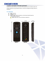
1
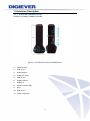
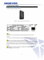
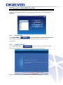
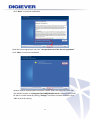
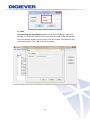
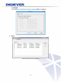
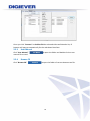
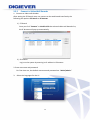
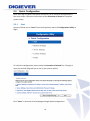
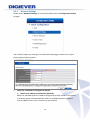
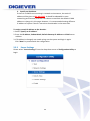
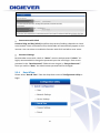
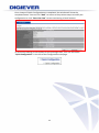
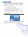
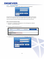
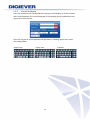
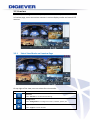
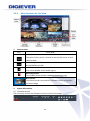
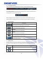
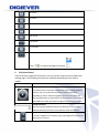
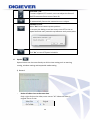
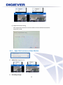
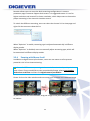
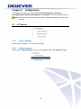
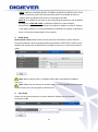
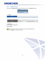
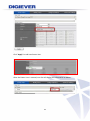
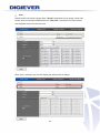
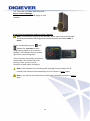
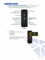
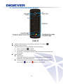
Video Wall Recorder User Manual V1.0.0.1 Information in this document is subject to change without notice. © Copyright 2014. All rights reserved. Table of Contents Chapter 1. 1.1 Introduction .............................................................................. 3 Hardware Description................................................................................... 4 1.1.1 Video wall decoder Series ................................................................ 4 Figure 1. Front & Rear View of VD-0000 Series............................................... 4 1.2 LED Indicators Status ..................................................................................... 5 1.2.1 1.3 Video Wall Decoder Series ............................................................... 5 Dual Display Solution: HDMI/ DVI-I Connection ...................................... 6 Chapter 2. Decoder Installation ................................................................. 7 2.1 Remote Browser PC System Requirements ............................................... 7 2.2 Connect to Video Wall Decoder ................................................................ 8 2.2.1 Quick Guide ....................................................................................... 8 2.2.2 Install EZ Search................................................................................ 8 2.2.3 User Manual ..................................................................................... 16 2.2.4 Browse CD ....................................................................................... 16 2.3 Quick Configuration ................................................................................... 18 2.3.1 Start .................................................................................................. 18 2.3.2 Network Settings ............................................................................. 19 2.3.3 Server Settings ................................................................................ 20 2.3.4 Date &Time ....................................................................................... 21 2.3.5 Camera Settings .............................................................................. 23 2.3.6 Finish ................................................................................................ 33 Chapter 3. 3.1 Use Video Wall Decoder by Local Display ........................... 35 Log in Decoder ............................................................................................ 35 1.1.1 Anonymous login ............................................................................ 36 1.1.2 Virtual Keyboard .............................................................................. 37 3.2 Liveview ........................................................................................................ 38 3.2.1 Select View Modes on Liveview Page ........................................... 38 3.2.2 Main Functions for Live View ......................................................... 39 i 3.2.3 Right Click Functions on Video Window ....................................... 43 3.2.4 Zooming with Mouse Scroll ............................................................ 44 Chapter 4. 4.1 Configuration .......................................................................... 46 IP Camera .................................................................................................... 46 4.1.1 Camera Settings .............................................................................. 46 4.1.2 Video Parameter .............................................................................. 46 4.1.3 Camera Status ................................................................................. 49 4.2 Network Setup ............................................................................................. 50 4.2.1 Network Setup ................................................................................. 50 4.2.2 Network Service ............................................................................... 52 4.3 Management ............................................................................................... 53 4.3.1 User Management............................................................................ 53 4.3.2 Log System ...................................................................................... 58 4.3.3 Load Configuration ......................................................................... 63 4.4 System ........................................................................................................... 64 4.4.1 Device Information .......................................................................... 64 4.4.2 System Upgrade .............................................................................. 65 4.4.3 Language.......................................................................................... 67 4.4.4 Date &Time ....................................................................................... 67 4.4.5 Reboot &Shutdown ......................................................................... 70 Chapter 5. Remote Controller (optional) ................................................ 71 5.1 Overview........................................................................................... 71 5.2 Connect to Video Wall Decoder ..................................................... 72 5.3 Instruction of Liveview Interface (Side A) ..................................... 73 5.4 Instruction of Mouse and Keyboard (Side B) ................................ 74 ii Chapter 1. Introduction Before You Use This Product When you first open the product’s package, verify that all the accessories listed on the “Package Contents” of “Quick Installation Guide” are included. Before installing the video wall decoder, please read the instructions in the “Quick Installation Guide” to avoid misuse. 3 1.1 Hardware Description 1.1.1 Video wall decoder Series VD-0025 / VD-0036/ VD0049/ VD-0064 Figure 1. Front & Rear View of VD-0000 Series 1. 2. 3. 4. 5. 6. 7. 8. 9. 10. 11. Power button USB 2.0 x 2 Audio output Audio mic input USB 2.0 x 2 Gigabit LAN x 1 HDMI x 1 eSATA x 1(reserved) DVI-I USB 3.0 x 2 Power connector 4 1.2 LED Indicators Status 1.2.1 Video Wall Decoder Series VD-0025/ VD-0036/ VD-0049/ VD-0064 Figure 2-3. Video Wall Decoder Series Front Panel Note: **To turn off your video wall decoder, long pressing power button at least 2 seconds. **To turn on your video wall decoder, long pressing power button at least 3 seconds. Note: To reset to default, please follow below methods: Press the power button twice with the interval of one second. In other words, please press the power button in the 1st second and press the power button again in the 2nd second. It will be easier to operate the reset to default with the assistance of watch or clock. Note: Once users press reset button, configuration of Camera Setting and Server Settings will reset to default. 5 1.3 Dual Display Solution: HDMI/ DVI-I Connection VD-0000 Series provide HDMI and DVI-I port for local display. Users can connect both of HDMI and DVI-I at the same time for video output. Scenario A:If both monitors are Full HD(1920x1080),those will be shown as Full HD. Scenario B: If both monitors are VGA (1024x768), those will be shown all as VGA. Scenario C: If one of monitors is 1920x1080 and another is 1024x768, both monitors are set as 1024x768 6 Chapter 2. Decoder Installation 2.1 Remote Browser PC System Requirements The following information is the minimum required specification for remote Windows PC, which users can open a remote browser from the PC to access the Linux decoder server on the network. Operating System Microsoft® Windows® Vista /7 / 8 (32-bit and 64-bit) Browsers in Windows OS (32-bit) Microsoft® Internet Explorer 8.0 or above, Chrome 31.0.1650.57m or above, Firefox 25 or above, Opera 17.0 or above, Safari5.1.7 or above 7 2.2 Connect to Video Wall Decoder To begin, please insert the product CD-ROM in a PC to access the Quick Guide, User Manual and install the utilities. As user runs the product CD, the following menu is displayed. 2.2.1 Quick Guide Click “Quick Guide” to enter the folder and double click the file to open. Please read Quick Guide to quickly understand the process of system installation. 2.2.2 Install EZ Search Click “Install EZ Search” to find system in the network. Please follow the instructions to install and EZ Search will run automatically. When installing EZ Search, Shield Wizard window for EZ Search will pop up. 8 Click “Next” to continue installation. Read the license agreement and click “I accept the terms of the license agreement”. Click “Next” to continue installation. Select a location of destination and select a folder where the setup can install files. The default location is: C:\Program Files (x86)\NVR\EZ Search. Users can also install EZ Search in other folder by clicking “Change” and select a location as below. Click “OK” to save the setting. 9 Once a folder is selected, please click “OK” to continue installation. The window shows that the Install Shield Wizard is installing video wall decoder Search. Please wait until the Wizard completes the installation. 10 The InstallShield has successfully installed EZ Search. Select “Create Desktop Shortcut”/ “Create Quick Launch Shortcut”/ “Create Start Menu Shortcut” and please click “Next” to continue. The installation is complete. Please click “Launch application when done installing” to execute video wall decoder Search. After finishing the setup, the window of video wall decoder Search will pop up. EZ Search will execute automatically and show NO., Name, IP Address, Mac Address and Model name of connected video wall decoder. 11 Users can click “Search” to search device. Introduction of Video Wall Decoder Search EZ search provides three kinds of toolbars for users: 1. File You can click “Exit” to leave EZ search and close the window. 12 2. Setting Configure UPnP and Network by clicking “Setting” in the top left or in the middle right. Note: Users will be prompted to enter the login information of Decoder before being allowed to change the setting. When accessing the video wall decoder setting, users will be prompted to enter username and password. For the first-time use, the default username and password are admin/admin. When the correct username and password have been entered, click “Login” to continue. 13 1) UPnP Universal Plug and Play (UPnP) simplifies the process of adding a video wall decoder to a local area network. Once connected to a LAN, Video wall decoder will automatically appear on the internet. You can rename UPnP Name on the video wall decoder. Click “OK” to finish the setting. 14 2) Network Two models are provided for setting the network: DHCP and Static IP. 3. Option Option provides several languages 15 Once you click “Connect” or double click the selected video wall decoder list, IE browser will pop up automatically for the web-based interface. 2.2.3 User Manual Click “User Manual” manual file to read. 2.2.4 to open the folder and double-click on user Browse CD Click “Browse CD” to open the folder of current Autorun.exe file. 16 2.2.5 Connect to Video Wall Decoder 1. Connect to video wall decoder After setting the EZ Search users can connect to the web-based interface by the following two options: EZ Search or IE browser 1) EZ Search Once you click “Connect” or double click the selected video wall decoder list, the IE browser will pop up automatically. 2) IE browser Log in to the system by entering its IP address in IE browser. 2. Enter username and password: For first-time use, the default username and password are “admin/admin.” 3. Select the languages for the UI. 17 2.3 Quick Configuration After users log in system, the system will direct you to set Quick Configuration in four main steps. Follow the instructions of the Overview of wizard to complete system setup. 2.3.1 Start System will lead you to “Start” from the drop-down menu of Configuration Utility to begin. To initial the configuration, please study the Overview of wizard first. Through 4 steps, the wizard will guide you to set up the system quickly. Click “Start” in Overview of wizard page to begin Quick Configuration. 18 2.3.2 Network Settings Please select “Network Settings” from the drop-down menu of Configuration Utility to begin. Users need to adjust the settings in the Network Setup page in order to let system work properly within network. There are 2 methods to configure IP address 1. Obtain an IP address automatically (Default) Obtain an available dynamic IP address assigned by a DHCP server. If this option is selected, system will automatically obtain an available dynamic IP address from the DHCP server once it connects to the network. 19 2. Specify an IP address. If there is no DHCP server existing in network environments, the static IP address will be given as192.168.1.245. It should be adaptable in most networking environment, and user can choose to maintain the default IP ddd address or change it in this page. However, it’s recommended setting different IP address of system if there is more than one decoder in the same LAN. To assign a static IP address to the decoder: 1. Select “Specify an IP address” 2. Enter the IP address, Subnet Mask, Default Gateway IP Address and DNS server address. 3. If IP Address is changed, user needs to log out the system and login in again. Click “Next” to proceed with the configuration. 2.3.3 Server Settings Please select “Server Settings” from the drop-down menu of Configuration Utility to begin. 20 Server name with UPnP Universal Plug and Play (UPnP) simplifies the process of adding a decoder to a local area network. Once connected to LAN, the decoder will automatically appear on the internet. User can select to enable the function with UPnP and edit a sever name. Password Settings Each decoder comes with a built-in “admin” account with password “admin.” It’s highly recommended to change the password upon the initial login. Enter a new password in the “New Password” field and enter it again in “Retype Password.” Since you confirm “Next,” the administrator password will be changed. 2.3.4 Date &Time Please select “Date & Time” from the drop-down menu of Configuration Utility to begin. 21 1. Manual setting Use the drop-down list and configure the time manually. Select the Year, Month, Date and Time. Time setting will be effective when you click “Next.” 2. Time Zone: Synchronize with an Internet time server automatically. Select the time zone of your area and update the date and time of the decoder automatically with an NTP server. User also has an option to automatically adjust daylight saving time. Configure the time and date by verifying and adjusting current local time and daylight saving to avoid the following errors: Incorrect display time for playback videos. Inconsistent display time of event logs and when they actually occur. Please enter the hostname of a valid NTP server to synchronize the server time with an Internet time server. NTP (Network Time Protocol) is a protocol to synchronize the clocks of a computer system. 22 2.3.5 Camera Settings Decoder provides two methods to add NVRs and cameras: UPnP Search and Detect 1. Detect: User can enter NVR or camera’s IP Address, username and password. Then, click “Apply” button to start adding device. User can add cameras through NVR or directly add camera to decoder: (1) Add cameras through NVR After applying correct NVR information, user will be directed to “Add all” page. 23 By clicking “Delete” button, user can delete the camera that you do not want to add to decoder. Please click “Add All” button to start adding cameras. (2) Directly add camera to decoder When successfully adding cameras, decoder will display camera information in camera list. Note: Camera Name, Username and Password are editable. After clicking “Apply” button, vender, username and password will be automatically filled in by vendor’s default information. 24 Memorize modified username and password: Decoder can memorize username and password which is modified by users after users click “Apply” button. Then, the default username and password of that vendor will be replaced by the modified one. Next time when users add new camera of the specific vendor, username and password will be automatically filled in by new modified one. Note: Each vendor has its own default username and password. Streaming Parameters Decoder provides two options to set up stream parameters: Optimization by decoder and Settings from camera. (1) Optimization by Decoder By selecting this option, decoder will optimize settings to perform the best surveillance efficiency. (2) Settings from camera If users have already set up camera settings from camera webpage, decoder can adopt camera setting by selecting “Setting from Camera.” This option can largely save users’ time and effort when users install surveillance systems. Note: It is highly recommend to use “Optimization by Decoder” to perform the best surveillance quality in both live-view and playback. 25 Multi-channel Video Server Decoder supports multi-channel video server to connect analog cameras to decoder. Users are asked to enter IP Address. Check correct username and password. Please click “Enable” Video Server and choose the channel number. Then, click “Apply” button. If there is any error occurred in entering the following information, the notification window will pop up as below. When an inappropriate address is entered, a window will pop up as below. When an inappropriate user name is entered, a window will pop up as below. When an inappropriate password is entered, a window will pop up as below. 26 Delete If any camera should be deleted from camera list, please click the column turning into blue and click “Delete” button. A window will pop up to ensure the action. To delete the camera, click “OK” to proceed. The camera has been deleted from camera list. Generic RTSP/ Generic MJPEG Decoder provides the interface for users to enter RTSP/ MJPEG URLs of IP cameras to receive the video streaming from IP camera. The streaming will be applied to monitoring, recording and playback. 27 Generic RTSP and Generic MJPEG function can be selected in the vendor list of camera setting page. Follow by entering the Generic URL column with proper RTSP or MJPEG URLs. If Generic RTSP is selected, RTSP port should be filled out too. Click “Apply” button to make parameters enable The most correct URLs should be provided from each camera vendors. Users may also refer to websites - https://www.soleratec.com/rtsp/ - http://www.ispyconnect.com/sources.aspx 28 2. UPnP Search: Click “UPnP Search” to find out UPnP devices within the LAN. Please make sure IP camera supports UPnP Search function. Please go to IP Camera web page to enable UPnP search function. Please wait. The UPnP search is in a process. The available cameras in the network will be displayed. The Added column will show two numbers to display the total channels of decoder and the channel numbers that has been already added in the decoder. Click the camera that you would like to add to decoder, then click “Add” button. Note: Users can click “All” to add cameras in Added column. 29 User can add cameras through NVR or directly add camera to decoder: (1) Add cameras through NVR When selecting a NVR to add to decoder, a window will pop out to ask NVR password. Please enter the correct password. Then, click “Connect” button. By clicking “Delete” button, user can delete the camera that you do not want to add in decoder. Please click “Add All” button to start adding cameras. (2) Directly add cameras to decoder If user directly adds camera in decoder, please check camera information in Group add page. Then, Click “Add All” button to start adding cameras 30 Note: Decoder will automatically fill in default username and password of each vendor. Camera No., Camera Name, User Name and Password can be modified by users. Memorize modified username and password: Decoder will memorize username and password which is modified by users after users click “Apply” button. Then, the default username and password of that vendor will be replaced by the modified one. Next time when users add new camera of the specific vendor, username and password will be automatically filled in by new modified one. Note: Each vendor has its own default username and password. Note: By clicking “All” option beside Username and Password, decoder will automatically memorize modified username and password of that camera brand. As above example, decoder will modify default username and password of AVTECH camera and make the new username and password become AVTECH’s default username and password. Status column in camera list will display “Successful” when cameras are successfully added in the decoder. 31 Please click “Go to Camera Settings” button to check all camera information camera list that is successfully added in the decoder. Multi-channel Video Server Decoder supports multi-channel video server feature to connect analog cameras to decoder. Please click “Enable” Video Server and choose the channel number. Please click “Add All” button after finishing checking all camera information. 32 Delete User can click “Delete” button to remove the camera from system. Please click a camera and click “Delete” button. A window will pop up to ensure the execution. Please click “OK” to proceed. 2.3.6 Finish Please select “Finish” from the drop-down menu of Configuration Utility to begin. 33 Once 4 steps of Quick Configuration are completed, the window will show the completed status. You can click “Back” to return to the previous steps to modify the configuration or click “Start Live view” to start monitoring at local liveview. To review the setting or information of Quick Configuration, user can also select “Quick Configuration” in the left of the Configuration main page. 34 Chapter 3. Use Video Wall Decoder by Local Display Video wall decoder can be connected to a monitor via HDMI and DVI port to execute quick configuration and display liveview. To start local display, please check the steps below: 1. Connect video wall decoder and IP cameras to the network. 2. Make sure the monitor is connected to the port (HDMI / DVI-I) of rear panel. 3. Please connect a USB mouse to the USB port of the decoder. 4. Please connect power cord and connector to turn on system. 5. When you enter the log in interface, please enter default user name “admin” and password “admin” and select languages. 3.1 Log in Decoder Users have to key in the correct username and password to login decoder Currently, Video Wall Decoder supports two resolutions: 1920 x1080 and 1024x768. It is highly recommend to use Full HD (1920 x 1080) to display the best video quality. 35 1.1.1 Anonymous login Anonymous login allows users to login without username and password. Anonymous user can only view live monitoring and playback page in local monitor, however, the configuration page will be disable. While anonymous login is applied, system will automatically log in without authorization process after boot up. Start to setup the anonymous login A. Please go to “Configuration->Management->Users Management->Advance Settings” in remote web browser. B. Check the “Enable Anonymous Access.” C. Enable the “Anonymous” at the local display login page, and then log in. 36 1.1.2 Virtual Keyboard Users can choose to use USB keyboard for typing on local display, or fill out columns with virtual keyboard. The virtual keyboard in local display can be enabled from the right side of each column. There are 3 types of virtual keyboard can be chosen, including Upper case, Lower case and Symbols. -Upper case -Lower case -Symbols 37 3.2 Liveview After the Quick Configuration is complete, users can successfully monitor IP cameras. In liveview page, users can monitor cameras in various display modes and control PTZ cameras. 3.2.1 Select View Modes on Liveview Page On top right of live view, users can select four view modes. Mode Description Liveview: Click “Liveview” to control the monitoring. Configuration: Click “Configuration” to configure IP camera, network, system, etc. Logout: Click " Logout" to leave decoder. 38 3.2.2 1. Main Functions for Live View Camera status Icon Description Camera name: The name of the camera is located in the top left corner in each video window. Video compression format: M-JPEG/MPEG-4/H.264 Audio: Once camera supports audio, decoder shows audio in blue. Vice versa, decoder shows audio in grey. Recording status: The window shows whether camera is recording or not. Blue border: The outline border surrounds the selected window to highlight the focus image. 2. System information (1) Firmware version User can easily find out the firmware version in the live view page. 39 (2) CPU loading indicator: Users can find out CPU loading directly without entering configuration page. CPU loading indicator shows blue when loading is 70% or under, and shows red as a warning when it reach to more than 70%. With changing the video configuration, like resolution, FPS and video quality, can influence the CPU loading, and users can easily find the best balance in Decoder. 3. Basic functions Icon Description Digital zoom in/ out: Select a channel to enable digital zoom function Drop: Drop the camera from monitoring. Drop all: Drop all cameras from monitoring. Add all: Add all cameras from monitoring. Mute: Alter sound instrument from camera. Date & Time: Show the day and time. 4. Display mode Decoder supports multi-display modes for monitoring. Click the icon of display mode to monitor liveview. When you click a display mode, the mode icons will turn into blue. Icon Description Full Screen 1 screen 40 4 screen 9 screen 12 screen 16 screen 20 screen 25 screen 5+1 screen Sequential mode Click to choose the page of liveview . 5. PTZ Control Panel If the IP camera supports PTZ function, user can use the control panel to adjust the viewing angle. The following functions are available depending on the camera models. Icon Description PTZ panel: PTZ allows users to monitor large areas with a single network camera. Pan, tilt, and zoom functions can be controlled remotely by users. If device supports PTZ control, users can click on the arrows to pan and/ or tilt the camera. The house in the middle can take you back to original monitoring position. Preset positions: Select the preset positions which are defined in PTZ camera and the camera will move to the position that user selects. Optical zoom in/ out: If camera supports PTZ control, users can adjust PTZ camera to zoom out or zoom in. 41 Focus near / far: If camera supports PTZ control, users can adjust the focus of the PTZ camera to focus near or focus far. Auto Focus: To automatically focuses the camera lens on a subject. Schedule for PTZ: Select “Set” to set camera preset position. It can open the dialog to set how many times PTZ cruise to repeat and how many seconds stay between each preset point. Schedule for PTZ: Click “Go” to start PTZ patrol schedule. 6. Option Option button can let users directly to do live-view setting such as warning setting, windows setting and sequential mode setting. 1) General Resize all video sizes at the same time Only a right click on the video, users can set "all" video size either in original size or fit size. 42 2) Sequential mode setting Click sequential interval to set the numbers of user-defined seconds for sequential mode. 3.2.3 Right Click Functions on Video Window 1. Video Size: Original or Fit 2. Streaming change: 43 Decoder allows users to setup the dual streaming configurations in camera parameter page if cameras support dual stream. It is suggested stream 1 is set for higher resolution and stream 2 for lower resolution, which helps users to choose the proper streaming in live view with intuitive control. To switch the different streaming, users can select the channel in live view page and right click the mouse to show the list. When “Optimize” is enable, streaming type is adjusted automatically in different display modes. When “Optimize” is disabled, users can manually adjust streaming type, which will be memorized in different display modes. 3.2.4 Zooming with Mouse Scroll In addition to digital zoom in/out button, users can use mouse scroll to prevent potential crisis in live-view monitoring. Note: For PTZ cameras, zooming with mouse in live-view is adopted optical zoom in/out. If users would like to view more detailed image, please use zooming with mouse scroll first and then click digital zoom in/out button. Please click on the video window and use mouse scroll to zoom in or zoom out image To press and hold left mouse button, drag the image to the place that you would like to monitor. 44 45 Chapter 4. Configuration In configuration page, users can configure Quick Configuration, IP Camera, Recording & Event, Network Management and System from each drop-down menu. Note: Decoder will automatically log out from configuration page after idle for 10 minutes. 4.1 4.1.1 IP Camera Camera Settings Please refer to Chapter2 - 2.3.5 Camera Settings. 4.1.2 Video Parameter Please select “Video Parameter” from the drop-down menu of IP Camera to begin. 46 Decoder supports multi-stream for monitoring and recording. Users can modify camera’s configuration such as video format, frame rate and resolution video quality in this page. Note: Camera adding through NVR cannot be edited its parameter. Please go to NVR’s configuration page to edit camera parameter. There are two parts in this section: Parameter and Camera List. Please select a camera in Camera List first. 47 As you click one column turning into blue, please wait and the window below will appear to allow users configure multi-stream. After loading camera’s information, users can modify camera parameter, except this camera is be added by video wall decoder. Camera No. Select a desired camera no. to add camera in decoder’s camera list. Stream 1/ Stream 2 (Recording Stream) Decide one stream as recording stream for video recording between stream 1 and stream 2 if cameras support dual streams. Note: It is suggested stream 1 is set for higher resolution and stream 2 for lower resolution, which helps users to choose the proper streaming on live view with intuitive control. Note: On liveview interface, decoder will display videos in stream 1 from 1-screen to 12-screen display mode. Decoder will display videos in stream 2 when display mode is above 16-screen. Video Format Choose a video compression format for live view and recording: MPEG4, H.264 and MJPEG. Note: Types of video format varies depending on the camera brands and models. 48 Frame Rate Select frame rate from drop-down list .Frame rate of IP camera will be influenced by the network surroundings. Resolution Select resolution from drop-down list for your camera. Video Quality Select either “VBR” (Variable bit rate) or “CBR” (Constant bit rate) to set the video quality. Enable Audio Recording To make audio recording function enable or disable. Enable Mobile Snapshot To make mobile snapshot function enable or disable. 4.1.3 Camera Status Please select “Camera Status” from the drop-down menu of IP Camera to begin. Camera List shows connection status of recording. 49 4.2 Network Setup 4.2.1 Network Setup Please select “Network Setup” from the drop-down menu of Network to begin. This section explains how to configure network connection with decoder. 1. Information Network information displays present network configuration including: Computer Name, IP address, Subnet mask, Default Gateway, Primary and Secondary DNS. 2. Setup Users can rename Computer Name and to assign DHCP or Static IP. 50 DHCP: Obtain an available dynamic IP address assigned by a DHCP server. If this option is selected, system will automatically obtain an available dynamic IP address from the DHCP server when connecting to the LAN. Static IP: If no DHCP server exists in the networking environment, the IP address will be given as192.168.1.245. It should be sufficient in most network environments, and users can maintain the default IP address or alter IP address in this page. However, it’s recommended to set different IP address of decoder if there is more than one decoder in the network. 3. DHCP Setup Built-in DHCP server allows users to easily install IP surveillance systems without connecting another router providing network parameters. With built-in DHCP server, decoder can assign local IP addresses to multiple IP cameras in a local area network (LAN). Note: Built-in DHCP server is available when LAN is specified an IP address (static IP). Note: Please do not connect to another device containing DHCP server function such as router when utilizing built-in DHCP server 4. Port Setup Please set up transmission port to access decoder. Default port for decoder connection is 80. 51 4.2.2 Network Service Please select “Network Service” from the drop-down menu of Network to begin. 1. UPnP Enable or disable UPnP search. Rename UPnP. Note:The maximum character limitation for UPnP Name is 32 characters. Please click “Apply” to execute the settings. 52 4.3 Management In Management, users can easily create, modify and change users' liveview access. Also, users can read various log information through log system and quickly save or load configuration of decoder. 4.3.1 User Management Select “User Management” from the drop-down menu of Management to begin. Decoder can be accessed by multiple users simultaneously. Except the built-in Administrator account (user name "admin" and password "admin"). Administrator can create other Power User and User accounts. Administrator possesses the highest privilege, compare to Power User and User. And Power User and User can be given different privilege of live view and playback of different channels. 1. Create Users Please go to “Create Users” page Power User Enter a username and password in “Create Users” page and select a group from the “Group” drop-down list to assign a new power user. Live View Access and Playback Access are selected automatically for Power User. 53 Click “Apply” to add new Power User. After the Power User is created, user list will display the information as below. 54 User Administrator can select a group from “Group” drop-down list to assign a new User. Please enter a username and password in “User List.” And select Live View Access and Playback Access for the new User. After User is created, user list will display the information as below. 55 2. Modify Users Please go to Modify User page. Select an account to modify the Power User or User. The selected account will turn to blue and the page for modifying user will appear as below. You can change Live View Access and Playback Access. Please click “Apply” to proceed. After User is modified, user list will display the renewed information. 56 To delete the user account, please click “Delete” from User List in Modify Users page. 3. Change Password Each decoder comes with a built-in “admin” account with password “admin” for administrators. It’s highly recommended to change the password upon the initial login. Select an account from “User Name” drop-down list to change password. Enter a new password in the “New Password” and enter it again in “Retype Password.” Click “Apply,” the password will be changed. 57 4. Advanced Settings In this page, users can set up anonymous access on local display, maximum users for remote login and configuration page timeout period. Anonymous access on local display Anonymous user can only view live monitoring and playback page on local monitor with no access of decoder configuration. Users can enable or disable this function in this page. For more information of anonymous login, please refer to 3.1.1 Anonymous login. 4.3.2 Log System Please select “Log System” from the drop-down menu of Management to begin. Log system provides four types of log record basic information for troubleshooting, including Hardware Log, Event Log, Current User, Historical User Log, and File Access Log. 58 Hardware Log The log information in Hardware Log includes CPU, buzzer, fan, system, sensor and USB. 59 System Log The log information in decoder Log includes time zone, daylight, system, firmware upgrading, configuration IP. 60 Historical User Log The log information in Historical User Log records any user who has logged in the system. For example, “Execute detect,” “Motion detected,” “Account is created,” “Execute system shutdown,” etc. 61 Current User The log information in Current User shows the current users logged in the system with IP address. 62 4.3.3 Load Configuration Please select “Load Configuration” from the drop-down menu of Management to begin. Load Default Configuration Once you select “Load Default Settings” and click “Apply,” configuration of Camera Setting, Recording Settings, Event & Action Setting, E-Mail settings, and Server Settings will reset to default. 63 4.4 4.4.1 System Device Information Please select “Device Information” from the drop-down menu of System to begin. System Information System Information shows Product Model, Firmware Version, MAC Address, Operating System, OS Version, CPU, Network Adapter and Locate. Locate Click "Locate", the buzzer will be triggered for 3 seconds. It helps the user to locate the system. 64 Enclosure Information Enclosure Information shows CPU Temperature and System Fan Speed. Note: Temperature of operation environment for decoder is 0~40˚C. 4.4.2 System Upgrade Users can do firmware upgrade via Local Display (connect directly to a local monitor via HDMI or DVI connector). Note: Please make sure the model and the firmware version are correct. Note: Please reboot the system before upgrading to accelerate and to save your process time. 1. Upgrade via Local Display (1) Download latest firmware file from website and save the firmware file to a local computer. (2) Completely unzip the file, and save it to USB device.Please save the file to your USB device after downloading and unzipping the firmware. Note: If you want to upgrade the system via USB device on local display UI, after downloading and unzipping the file, please rename the unzipped .bin file name to "update.bin" in the USB device, in order t have it recognized by the local system correctly. Note: To recognize the USB device well, please format the USB device to FAT32 file system first, and make sure you delete all other files and keep only “update.bin”) 65 Instructions to format a USB device to FAT32 file system: I. Click on the "My Computer" shortcut on the desktop of your computer II. Right-click the flash drive and choose the "Format" option III. Change the selection under "File System" to FAT32 IV. Click the "Start" button to begin the formatting process (3) Connect decoder to a monitor and insert USB device to the port of video wall decoder To start local display upgrade, please connect decoder to a monitor (via HDMI or DVI) and insert USB device to the USB port. (4) Power on the monitor and video wall decoder, and log in video wall decoder. (5) Go to "Configuration" page, and then select "System Upgrade". When the interface shows device is ‘ready’, you can start upgrading the system. (6) Once firmware upgrade finishes, video wall decoder will reboot itself. Users could go to “Device Information” from the drop down list of “System” so as to double check firmware version. 66 4.4.3 Language Please select “Language” from the drop-down menu of System to begin. Decoder provides different languages for users. Users can configure the language as AUTO or other languages. Please click “Apply” and the language will be changed. 4.4.4 Date &Time Please select “Date & Time” from the drop-down menu of System to begin. 1. Set up 67 Select from the drop-down list and configure the time manually and the setting will be effective when you click “Apply”. 2. Time zone Users can set the time and date according to the correct time zone and adjust clock for daylight saving changes for your preference. Please enter the hostname of a valid NTP server to synchronize with external NTP server. Automatically sync User can also decide when to automatically synchronize with external NTP server by selecting “Automatically Sync”. Based on users’ preference, system provide three selections to automatically synchronize with external NTP server: Monthly, Weekly or Daily. 68 (1) Select “Automatically Sync” (2) Set up when to automatically synchronize with external NTP sever (3) Fill in the number to start auto synchronize when time difference is over user defined seconds (4) Click “Apply” button to save setting Note: The file recorded in overlapping time will be saved in “time overlap” after the system synchronized with NTP server Built-in NTP server To ensure the accuracy of time, decoder provides NTP server function for client device to synchronize the time clock. The built-in NTP server address follows decoder IP address. 69 4.4.5 Reboot &Shutdown Please select “Reboot & Shutdown” from the drop-down menu of System to begin. Click “Reboot” to restart the decoder. Click “Shutdown” to turn off the decoder. 70 Chapter 5. Remote Controller (optional) Remote controller allows user to select various options such as: Display mode, PTZ control, Sequential, Log, Snapshot, Option, Liveview, Configuration page, Mouse & Keyboard. 5.1 Overview Band : 2.4 GHz Distance : 10m Battery Types: Alkaline batteries, nickel metal hydride batteries, nickel-cadmium batteries Note: Please do not mix old and new batteries. 71 5.2 Connect to Video Wall Decoder Step 1. Insert USB dongle: Please insert controller’s USB dongle to your decoder. Step2. Enter programming mode to connect decoder: Note: To successfully connect to the decoder, please stay close to the decoder. The distance between USB dongle and remote controller should be within 1 meter. Please simultaneously press and buttons for 3 seconds to enter programming mode so as to connect decoder. The indicator will turn to blue light when you pressing them. If the controller successfully connects to the decoder, the indicator will start blinking. Then, you can use the functions on both side A and side B. Note: If the indicator has no blinking after pressing the two buttons for 30 seconds, the indicator will automatically turn off. Please try step 2 again. Note: If you cannot use the function on both side A and side B, please try step 2 again. 72 5.3 Instruction of Liveview Interface (Side A) Users can directly operate liveview interface on local display through remote controller. Please refer to below picture for more information. “FN” button On the side A, there are two functions of some buttons: (1) white word (2) blue word Users are able to alter functions by pressing “FN” button. The default setting is the functions in white word. 73 5.4 Instruction of Mouse and Keyboard (Side B) Enable mouse function: put side B up, and press “Fn” button Disable mouse function: The mouse function will be disabled in below situations: 1. Press “Fn” button on sideB 2. Turn to Side A for liveview operation 3. No actions, including pressing the button and move the controller, for 10 seconds Mouse speed: Speed types: The mouse offers four speed types from 1(slow) to 4(fast) for your preference. The default speed is 3. Change speed type: To change mouse speed, please simultaneously press “blue” and “red” button to next speed. 74 Appendix: Notice and Warning Notice *This equipment is for home use, and has acquired the electromagnetic conformity registration. So, it can be used not only in residential area, but also other areas. *이기기는가정용(B 급) 전자파적합기기로서주로가정에서사용하는것을목적으로하며, 모든지역에서사용할수있습니다. Warning *Risk of explosion if battery is replaced by an incorrect type. Please dispose of used batteries according to the instructions. 75