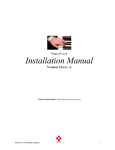
1
UniVision Engineering Limited UVN3000 Network Surveillance System User Manual Revision 1.00 UniVision Engineering Limited (Hong Kong) has been registered by SGS Yarsley ICS against ISO 9001 Certificate No.:Q13116 ISO 9001:1994 Information furnished by UniVision Engineering Limited is believed to be accurate and reliable. However, no responsibility is assumed by UniVision Engineering Limited for its use; nor for any infringement of patents or other rights of third parties which may result from its use. No license is granted by implication or otherwise under any patent or patent right of UniVision Engineering Limited. UVN3000 Network Surveillance System Revision 1.00 User Manual Table Of Contents Safety Precautions ............................................................................................... 1 Warranty................................................................................................................ 4 Copyright .............................................................................................................. 5 1 Introduction.................................................................................................... 6 1.1 General Description ............................................................................................. 6 1.2 Functions Description .......................................................................................... 6 1.3 General Layout .................................................................................................... 7 2 Installation...................................................................................................... 8 2.1 Unpacking............................................................................................................ 8 2.1.1 Packing List ............................................................................................ 8 2.2 System Setup ...................................................................................................... 8 2.2.1 System Components .............................................................................. 8 2.2.2 System Design Planning......................................................................... 9 2.2.3 System Connections............................................................................. 11 2.2.4 System Software Configuration ............................................................ 14 2.3 Expansion .......................................................................................................... 22 3 2.3.1 Expansion of Video Matrix Switchers in UVN3000 Network .................. 22 2.3.2 Expansion of UVN3000-P with UVN3000-SP Master Network Server .. 22 Operation...................................................................................................... 24 3.1 General Description ........................................................................................... 24 3.2 Keyboard Operation........................................................................................... 24 3.3 UV2000/II Operation .......................................................................................... 26 3.4 Exiting the UVN3000-P Program........................................................................ 27 3.5 Shutting Down the UVN3000-P Program ........................................................... 27 3.6 Saving the Event Log message ......................................................................... 27 4 Specifications .............................................................................................. 28 4.1 Performance ...................................................................................................... 28 5 Troubleshooting Hints................................................................................. 29 Copyright © UniVision Engineering Ltd. All Rights Reserved. Page i of iv UVN3000 Network Surveillance System Revision 1.00 Appendix A User Manual Removing the Monitor Overlay using the “User Function 6” from the Control Keyboard ........................................................30 Page ii of iv Copyright © UniVision Engineering Ltd. All Right Reserved. UVN3000 Network Surveillance System Revision 1.00 User Manual Table Of Figures Figure 1 Basic Structure of UVN3000 Network Surveillance System ............................................6 Figure 2 Typical System Block Diagram.........................................................................................7 Figure 3 Example of UVN3000 Network System .........................................................................10 Figure 4 Connections between the UVN3000-P and Video Matrix...............................................11 Figure 5 Setting of “RS-232 to RS-422 Converter”.......................................................................12 Figure 6 Connections of the Video Signals among two particular Video Matrix Switchers ..........13 Figure 7 Connections between UV3000-P and PC workstations (with UV2000/II) ......................14 Figure 8 Main Menu of UVN3000-P Communication Software Program .....................................15 Figure 9 Program Logon Password..............................................................................................16 Figure 10 Switcher Properties ........................................................................................................16 Figure 11 Switcher List ...................................................................................................................16 Figure 12 Port Properties Dialogue ................................................................................................17 Figure 13 Switcher List (Switcher Ready).......................................................................................18 Figure 14 Event Log Window (Successful Initialisation).................................................................18 Figure 15 Video Path Properties ....................................................................................................18 Figure 16 Video Path List ...............................................................................................................19 Figure 17 Client Properties.............................................................................................................19 Figure 18 MV2000 Client List .........................................................................................................20 Figure 19 Event Log Window (Successful Client Connection) .......................................................20 Figure 20 Event Log Window (Client Disconnection) .....................................................................21 Figure 21 Change Password ..........................................................................................................21 Figure 22 Expansion to the Full Capacity of the UV3000-P Network Server .................................22 Figure 23 UVN3000-SP Master Network Server ...........................................................................23 Figure 24 Monitor Overlays of the Local and Remote Switchers ...................................................25 Figure 25 System Diagram for the Example of Remote Camera Switching ..................................25 Figure 26 Indication of a Video Trunk Occupation (Keyboard Operator) .......................................25 Figure 27 Video Display Widow in UV2000/II Program ..................................................................26 Figure 28 Indication of a Video Trunk Occupation (UV2000/II Client)............................................26 Figure 29 Saving the Event Log Message......................................................................................27 Copyright © UniVision Engineering Ltd. All Rights Reserved. Page iii of iv UVN3000 Network Surveillance System Revision 1.00 User Manual Table Of Tables Table 1 Video Paths Assignment ................................................................................................10 Table 2 Dip-Switch Setting for MV900B Video Matrix Switcher ..................................................12 Table 3 Dip-Switch Setting for Monitor Expansion Configuration (MON Bay 1).........................13 Table 4 Port Assignment of the Multi-I/O Ports Module Box .......................................................15 Table 5 Remote Camera Switching.............................................................................................24 Table 6 Troubleshooting Hints.....................................................................................................29 Page iv of iv Copyright © UniVision Engineering Ltd. All Right Reserved. UVN3000 Network Surveillance System Revision 1.00 User Manual Safety Precautions 1. Read Instructions Read all safety and operating instructions before operating the unit. 2. Retain Instructions The safety and operating instructions should be retained for future reference. 3. Cleaning Unplug the unit from the outlet before cleaning. Do not use liquid cleaners or aerosol cleaners. Use a damp cloth for cleaning. 4. Attachments Do not use attachments not recommended by the product manufacturer as they may cause hazards. 5. Water and Moisture Do not use this unit near water - for example, near a bathtub, wash bowl, kitchen sink, or laundry tub, in a wet basement, near a swimming pool, in an unprotected outdoor installation, or any area, which is classified as a wet location. 6. Accessories Any mounting of the unit should follow the manufacturer’s instructions, and should use a mounting accessory recommended by the manufacturer. 7. Ventilation Openings in the enclosure, if any, are provided for ventilation and to ensure reliable operation of the unit and to protect it from overheating; these openings must not be blocked or covered. The openings should never be blocked. This unit should not be placed in a built-in installation unless proper ventilation is provided or the manufacturer’s instructions have been adhered to. 8. Power Sources This unit should be operated only from the type of power source indicated on the marking label. If you are not sure of the type of the power supply you plan to use, consult your appliance dealer or local power company. For units intended to be operated from battery power, or other sources, please refer to the operating instructions. 9. Grounding or Polarization This unit may be equipped with a polarized alternating-current line plug (a plug having one blade wider than the other). This plug will fit into the power outlet in only one way. This is a safety feature. If you are unable to insert the plug fully into the outlet, try reversing the plug. If the plug should still fail to fit, contact your electrician to replace your obsolete outlet. Do not defeat the safety purpose of the polarized plug. Alternately, this unit may be equipped with a 3-wire grounding-type plug, a plug having a third (grounding) pin. This plug will fit into a grounding-type power outlet This is a safety feature. If you are unable to insert the plug into the outlet, contact your electrician to replace your obsolete outlet. Do not defeat the safety purpose of the grounding-type plug. Copyright © UniVision Engineering Ltd. All Rights Reserved. Page 1 of 30 UVN3000 Network Surveillance System Revision 1.00 User Manual 10. Power-Cord Protection Power-supply cords should be routed so that they are not likely to be walked on or pinched by items placed upon or against them, paying particular attention to cords at plugs, convenience receptacles, and the point where they exit from the appliance. 11. Overloading Do not overload outlets and extension cords as this can result in a risk of fire or electric shock. 12. Object and Liquid Entry Never push objects of any kind into this unit through openings as they may touch dangerous voltage points or short-out parts that could result in a fire or electric shock. Never spill liquid of any kind on the unit. 13. Servicing Do not attempt to service this unit yourself as opening or removing covers may expose you to dangerous voltage or other hazards. Refer all servicing to qualified personnel. 14. Replacement parts When replacement parts are required, be sure the service technician has used replacement parts specified by the manufacturer or have the same characteristics as the original part. Unauthorized substitutions may result in fire, electric shock or other hazards. 15. Safety Check Upon completion of any services or repairs to this unit, ask the service technician to perform safety checks to determine that the units are in proper operating condition. 16. Coax Grounding If an outside cable system is connected to the unit, be sure the cable system is grounded. 17. Lightning For added protection of this unit during a lightning storm, or when it is left unattended and unused for long periods of time, unplug it from the wall outlet and disconnect the cable system. This will prevent damage to the unit due to lightning and power-line surges. 18. Damage Requiring Service Unplug the unit from the outlet and refer servicing to qualified service personnel under the following conditions: a) When the power-supply cord or plug is damaged. b) If liquid has been spilled, or objects have fallen into the unit c) If the unit has been exposed to rain or water. d) If the unit does not operate normally by following the operating instructions. Adjust only those controls that are covered by the operating instructions as an improper adjustment of other controls may result in damage and will often Page 2 of 30 Copyright © UniVision Engineering Ltd. All Right Reserved. UVN3000 Network Surveillance System Revision 1.00 User Manual require extensive work by a qualified technician to restore the unit to its normal operation. e) If the unit has been dropped or the cabinet has been damaged. f) When the unit exhibits a distinct change in performance-this indicates a need for service. Copyright © UniVision Engineering Ltd. All Rights Reserved. Page 3 of 30 UVN3000 Network Surveillance System Revision 1.00 User Manual Warranty UniVision Engineering Limited warrants this product when purchased, new to be free from defects for a period stated in the contract from date of shipment to the original purchaser. Under proper conditions of installation and use, exhibits such defects, will be repaired or replaced, at UniVision’s option. Transportation charges to UniVision shall be prepaid by purchaser if repairs are to be performed at the factory. This warranty will be void if UniVision product is subjected to misuse, accident, neglect, or improper application, nor repaired or altered by other than UniVision or those authorized by UniVision in writing. Products manufactured by companies other than UniVision are warranted by the original manufacturer. No contingent liabilities are assumed. UniVision has no responsibilities whatsoever if other applications cannot be properly performed after installation of the product. UniVision reserves the right to alter the information in this manual without prior notice. Page 4 of 30 Copyright © UniVision Engineering Ltd. All Right Reserved. UVN3000 Network Surveillance System Revision 1.00 User Manual Copyright The product mentioned in this document is copyright to UniVision Engineering Limited. All the copyright of the respective products which may have been mentioned in this document belong to the original product supplier or/and manufacturer. Copyright © UniVision Engineering Ltd. All Rights Reserved. Page 5 of 30 UVN3000 Network Surveillance System Revision 1.00 User Manual 1 Introduction 1.1 General Description (a) (b) The Surveillance System Network is made much more simple and flexible, less limitation with the revolutionary UVN3000 network configuration. It is designed for large surveillance system which requires wide area surveillance facilities. Unlimited number of sites may be linked together and have access of the cameras on each site through UVN3000 network. The UVN3000 Network comprises of multiple video matrix switchers connected in a star manner with a system server – UVN3000-P. The UVN3000-P performs central management, having full control of all other video switching stations in the network. Simulating a digital data network, enabling real-time display, wide area network connection and data sharing. Monitor ιον ΙΡΙΣ ΙΡΙΣ ΦΟΧΥΣ ΦΟΧΥΣ ΖΟΟΜ ΟΠΕΝ ΦΑΡ ΖΟΟΜ ΤΕΛΕ ΧΛΟΣΕ ΝΕΑΡΩΙ∆Ε Υνιςισιον Υνιςισιον Μς300Κ Μς300Κ Monitor Monitor ιον ΙΡΙΣ ΙΡΙΣ ΦΟΧΥΣ ΦΟΧΥΣ ΖΟΟΜ ΟΠΕΝ ΦΑΡ ΖΟΟΜ ΤΕΛΕ Μονιτορ Χαµερα Νο. Νο. ΣΕΤ ΣΗΟΩ ΟΝ ΟΦΦ ΑΛΜ ΠΓΜ ΡΥΝ ΜΟΝ 1 2 3 4 5 6 7 8 9 10 ΧΛΡ ΕΝΤ ΧΛΟΣΕ ΝΕΑΡΩΙ∆Ε Υνιςισιον Υνιςισιον Μς300Κ Μς300Κ Keyboard Μονιτορ Χαµερα Νο. Νο. ΣΕΤ ΣΗΟΩ ΟΝ ΟΦΦ ΑΛΜ ΠΓΜ ΡΥΝ ΜΟΝ Monitor ιον 1 2 3 4 5 6 7 8 9 10 ΧΛΡ ΕΝΤ Keyboard ΙΡΙΣ ΙΡΙΣ ΦΟΧΥΣ ΦΟΧΥΣ ΖΟΟΜ ΟΠΕΝ ΦΑΡ ΖΟΟΜ ΤΕΛΕ ΧΛΟΣΕ ΝΕΑΡΩΙ∆Ε Υνιςισιον Υνιςισιον Μς300Κ Μς300Κ ιον ΙΡΙΣ ΙΡΙΣ ΦΟΧΥΣ ΦΟΧΥΣ ΖΟΟΜ ΟΠΕΝ ΦΑΡ ΖΟΟΜ ΤΕΛΕ Μονιτορ Χαµερα Νο. Νο. ΣΕΤ ΣΗΟΩ ΟΝ ΟΦΦ ΑΛΜ ΠΓΜ ΡΥΝ ΜΟΝ 1 2 3 4 5 6 7 8 9 10 ΧΛΡ ΕΝΤ ΧΛΟΣΕ ΝΕΑΡΩΙ∆Ε Υνιςισιον Υνιςισιον Μς300Κ Μς300Κ Keyboard Μονιτορ Χαµερα Νο. Νο. ΣΕΤ ΣΗΟΩ ΟΝ ΟΦΦ ΑΛΜ ΠΓΜ ΡΥΝ ΜΟΝ 1 2 3 4 5 6 7 8 9 10 ΧΛΡ ΕΝΤ Keyboard Video signals MV900B Video Matrix Switch 1 Cameras Video signals COM2 Control signal COM Port Figure 1 1.2 Cameras COM2 Control signal UVN3000-P COM Port Basic Structure of UVN3000 Network Surveillance System Functions Description (a) (b) (c) (d) (e) Page 6 of 30 MV900B Video Matrix Switch 2 Any of the video matrix switchers connected in the UVN3000 network could view and switch video images of the others. The same applies to the control capability of the pan/tilt unit and lenses of the entire network. Operator priority level of any of the stations can be altered as required by the system administrator on the network server – UVN3000-P. Switching sequences could be run and programmed on demand on any of the switching stations/sites. Utilisation of the transmission media is optimised where only a single line is required for multiple monitors to view the same remote video image. Every station/site shares the same data and facilities in the UVN3000 network. Central Management ensures that all information including time, broadcast messages and alarm messages etc. are consistent. Copyright © UniVision Engineering Ltd. All Right Reserved. UVN3000 Network Surveillance System Revision 1.00 (f) 1.3 User Manual UVN3000 Network effectively reduces the cost and time for cable installation for the remote sites. All the signals including video and control are transmitted over the network connection. General Layout (a) A typical system block diagram of bi-directional accessing the video signals from different switching stations/sites is shown in Figure 2. Video I/P Video I/P Video O/P Video I/P MV900B Video Matrix Switch ιον MV900B Video Matrix Switch COM2 Control signal Control signal Video O/P Camera signal input COM2 Video I/P Video O/P UVN3000-P UVN3000-P Video I/P Video O/P COM2 Control signal Control signal MV900B Video Matrix Switch Video I/P COM2 MV900B Video Matrix Switch Video O/P ιον Video O/P Video I/P Video O/P Video I/P ~~ All All the the sites sites can can access access any any camera camera from from any any other other sites. sites. ~~ Figure 2 (b) Typical System Block Diagram For a single star connection, up to a maximum of 64 video switching systems (stations) can be connected together. For details, please refer to section 2.3. Copyright © UniVision Engineering Ltd. All Rights Reserved. Page 7 of 30 UVN3000 Network Surveillance System Revision 1.00 2 Installation 2.1 Unpacking User Manual Unpack carefully. This is an electronic equipment and should be handled with care. 2.1.1 Packing List (a) Check for the following items after unpacking UVN3000-P. Item Qty. Remarks UVN3000-P Network Server with MultiI/O card (AccelePort Xem PCI Host Adapter) installed 1 UVN3000 Communication Software program 1 One 3.5” floppy disk. AccelePort PORTS/8emTM Module or AccelePort PORTS/16emTM Module X The number of output ports depends on the number of video switcher connected in the system. Ic485-I RS-422 to RS-232 converters X The number of converters being used depends on the number of output ports. USB Security Key 1 User Manual for UVN3000 Network 1 This manual. Surveillance System NOTE1: AccelePort PORTS/8emTM supports up-to 8 video matrix switchers while AccelePort PORTS/16emTM supports up-to 16 video matrix switchers. NOTE2: MV900B Video Matrix Switcher is not included in the package and it shall be ordered separately. (b) Should any item appear to have been damaged during shipment, repack it properly in its original carton and contact our Customer Service Department. 2.2 System Setup 2.2.1 System Components (a) (b) (c) Page 8 of 30 UVN3000 Network consists of three major group of components namely, the high level, mid-level and the front end components. In the high level, it is the UVN3000-P Network Server. This is the heart of the UVN3000 network. High level integration including communications, controls, administrative management and information storage is handled by the UVN3000P. The hardware and software configuration of the UV3000-P include the following: (i) Microprocessor of Pentium II/266 or above; (ii) Windows 2000 operating system; (iii) UVN3000 Communication Software (UVN3000.exe) (iv) Free Harddisk space of 1.5GB or above; (v) 3.5” Floppy disk driver; (vi) 64MB or above RAM; Copyright © UniVision Engineering Ltd. All Right Reserved. UVN3000 Network Surveillance System Revision 1.00 (d) (e) (f) (g) 2.2.2 User Manual (vii) Multi-I/O card; (viii) Multi-I/O ports module box with a set of RS-422-to-RS-232 converters; (ix) 10M/100M Ethernet card (Optional) Mid-level of the UVN3000 network comprises of video matrix switchers, Alarm Interface Unit and so forth. The video matrix switchers handle first level of signal receiving, configuration and distribution of the front-end components. Other mid-level components include equipment with serial interface and auxiliary video components such as video splitter units, Video Distribution Amplifier (VDA) and Video Cassette Recorder (VCR). These could further enhance the system control. The Alarm Interface Unit collects all the alarm information from the alarm sensors before directing them to the UVN3000-P Network Server. The Front-end components include cameras, pan/tilt units, On-Site Receiver/Driver (OSRD) and all types of alarm sensors. System Design Planning (a) (b) (c) Planning the overall UVN3000 network system is very important. The followings are some basic guidelines for constructing the UVN3000 network system: (i) How many sets of video switchers (stations) to be connected in the network system? (ii) Where is the UVN3000-P to be located? (e.g. to be located with a particular station.) (iii) Priority of each station. (iv) Distributions of the video inputs and outputs for each station to other different station(s). (v) Maximum of video channels for accessing each particular station by other stations. (vi) Consider the physical location of each station. After considering the above points, you may draw out a simple system block diagram with all the necessary video paths and then summarise all the video paths in a table format. An example of an UVN3000 network system with four(4) video switching systems (stations) is illustrated in Figure 3 in which the UV3000-P network server is installed in the location of Station#1. Thus, Station#1 can be considered as the master station and others as the slave stations. Copyright © UniVision Engineering Ltd. All Rights Reserved. Page 9 of 30 UVN3000 Network Surveillance System Revision 1.00 User Manual M3 M4 MV900B Video Matrix Switch (Station 4) I/P1 I/P2 I/P3 I/P4 M3 M1 M2 COM4 M4 I/P1 I/P2 UVN3000-P UVN3000-P MV900B Video Matrix Switch (Station 3) I/P2 I/P1 M2 COM3 COM1 M1 MV900B Video Matrix Switch (Station 1) I/P3 I/P4 COM2 I/P1 I/P2 M3 M4 NOTE: Switcher/Station ID 1 2 3 4 Figure 3 (d) Item M1 M2 Priority 1 2 3 4 Example of UVN3000 Network System From the system block diagram (e.g. Figure 3), you can summarise all the video paths assignment among the video matrix switchers in the following table. This organised information will be useful when configuring the UVN3000-P. From Switcher/Station ID Video Output (M) 1 2 1 2 2 2 3 2 3 4 2 4 5 3 1 6 3 2 7 3 3 8 3 4 9 4 1 10 4 2 11 4 3 12 4 4 *NOTE: Camera logical ID numbers. Table 1 Page 10 of 30 MV900B Video Matrix Switch (Station 2) --------------------> --------------------> --------------------> --------------------> --------------------> --------------------> --------------------> --------------------> --------------------> --------------------> --------------------> --------------------> To Switcher/Station ID 1 1 3 3 2 2 4 4 1 1 3 3 *Video Input (I/P) 3 4 1 2 1 2 3 4 1 2 3 4 Video Paths Assignment Copyright © UniVision Engineering Ltd. All Right Reserved. UVN3000 Network Surveillance System Revision 1.00 2.2.3 User Manual System Connections The UVN3000 network employs various system connection methods. The Star connection is used for data communications. As for video transmission, UVN3000 supports any topology available. Therefore, there are two main connections to be performed: 2.2.3.1 Control Data Connections between UVN3000-P and other video matrix switchers/stations (a) Connect the cable from the adapter card of the UVN3000-P to the connector labelled EBI IN on the Multi-I/O ports module box as shown in Figure 4. UVN3000-P Power cord Multi-I/O ports module box 1 5 9 13 2 6 10 14 3 7 11 15 4 8 12 16 Power Supply 110V/220Vac Multi-I/O port card X 16 Conve TD rter Conve RD TD RS-232 to RS-422 Converters T-ON/ R-ON 4 3 2 1 rter USB Security Key RD T-ON/ R-ON 4 3 2 1 100/10MbaseT Ethernet Adapter card (Optional) LAN cable To COM2 ports of the required MV900B Video Matrix Switchers Figure 4 (b) (c) From 100Mbase T Hub Connections between the UVN3000-P and Video Matrix Connect the USB Security Key to the USB port of UVN3000-P; Set the setting of “RS-232 to RS-422 converter” to DCE, MON and T-ON/R-ON as indicated in Figure 5 and connect the 4 cores cable to pins 1, 2, 3 and 4; Copyright © UniVision Engineering Ltd. All Rights Reserved. Page 11 of 30 UVN3000 Network Surveillance System Revision 1.00 User Manual erter v n o C TD Pin assignment for COM2 port of MV900B (Female connector) RD DCE DTE MON SIM T-RTS R-ON T-RTS R-ON Pin # COM2 port 1 2 3 4 5 6 7 8 9 Chassis GND TX+ TXRX+ RXGND GND GND GND T-ON/R-ON 4 3 2 1 NOTE: Set to DCE Set to MON Set to T-ON/R-ON To COM2 port of MV900B Figure 5 (d) (e) (f) (g) (h) Function: Setting of “RS-232 to RS-422 Converter” Connect a “RS-232 to RS-422 converter” to each required port of the Multi-I/O ports module box; Connect Port 1 of the Multi-I/O ports module box with a “RS-232 to RS-422 converter” to the COM2 port of the required video matrix switcher. (NOTE: The pin assignment of COM2 port of the MV900B video matrix switcher is shown in Figure 5.); Repeat step (e) for connection between the Multi-I/P ports module box with a “RS-232 to RS-422 converter” and another video matrix switcher until all the required video matrix switchers have been connected. (NOTE: For a single MultiI/O ports module box, a maximum of 16 video matrix switchers can be connected. However, up to a maximum of 4 Multi-I/O ports module boxes can be cascaded, making up a maximum of 64 video matrix switchers.); Connect the power cord to the PC workstation and then plug the cord into properly grounded electrical outlet and then power on the unit; Finally, set the dip-switch (SW1) on the MV910 CPU card of each MV900B video matrix switcher connected in the UVN3000 network to the following settings: SW1-1 SW1-2 SW1-3 Disable/Enable keyboard registration Warm/Cold startup Single-bay (As a expander)/ Monitor Expansion OFF/ON OFF/ON OFF/ON Table 2 SW1-4 SW1-5 SW1-6 SW1-7 UVN3000 Network Application ON ON ON SW1-8 Network ON Dip-Switch Setting for MV900B Video Matrix Switcher NOTE: If monitor expansion configuration has been configured for a particular station, the SW1-3 must be set to ON for the master bay and the slave bay (monitor bay 1) shall have the following dip-switch setting: (For monitor bay 2, SW1-4, SW1-5 and SW1-6 are set to OFF, ON and OFF respectively in binary format and so on for other required monitor bays.) Page 12 of 30 Copyright © UniVision Engineering Ltd. All Right Reserved. ON UVN3000 Network Surveillance System Revision 1.00 Function: SW1-1 SW1-2 SW1-3 Disable keyboard registration Warm startup As a expander OFF OFF OFF Table 3 2.2.3.2 User Manual Dip-Switch Setting (MON Bay 1) SW1-4 SW1-5 SW1-6 Monitor Bay ID No OFF for OFF Monitor SW1-7 SW1-8 As a expander Reserved ON ON ON Expansion Configuration Video Signal Connections among the video matrix switchers/stations (a) Connect the particular video outputs of the corresponding switcher/station to the corresponding video inputs of the required switcher/station based on the predefined system diagram. (An example of the video signal connections between two video matrix switchers is illustrated in Figure 6.) video input BNC connectors SDA Video I/P #1 BP input Video I/P #2 Biphase output MV900B Video Matrix Switcher (Station 1) console Ext. Sync To Vid eo I/P #3 To Vid eo I/P #4 alarm printer aux com1 com2 From UVN3000-P (via Multi-I/O ports module box) Power camera #176 SDA BP input From Biphase output MV900B Video Matrix Switcher (Station 2) console Ext. Sync alarm printer aux com1 com2 From Figure 6 (b) 2.2.3.3 Monitor #1 MON #1 2 O/P # Example: From Switcher 2 (Monitor O/P 1 & 2) to Switcher 1 (Camera I/P 3 & 4) Power Monitor #16 O/P MON Monitor #2 Connections of the Video Signals among two particular Video Matrix Switchers Repeat step (a) until all the required video connections have been completed. Connections between UVN3000-P and PC workstations with UV2000/II programs(Optional) UV3000-P network server can also work as MV2000 Communication Server and is able to handle commands from the PC workstations with UV2000/II programs directly via LAN. The main difference between UV3000-P network server and MV2000 communication server in the application with UV2000/II is that the UV3000-P is able to control each connected MV900B video matrix switcher in the network. The steps for connections between the UV3000-P network sever and PC workstations with UV2000/II are as follows: (a) Firstly, make sure each PC workstation with UV2000/II has been installed with a LAN interface card, video capture card(s) and the UV2000/II software program. (NOTE: Please refer to the UV2000/II 4.0 user manual for detailed installations of the UV2000/II software program and video capture card.) (b) Secondly, connect the UVN3000-P (Ethernet port) as shown in Figure 7 to the 1000Base-TX LAN hub; Copyright © UniVision Engineering Ltd. All Rights Reserved. Page 13 of 30 UVN3000 Network Surveillance System Revision 1.00 (c) User Manual Thirdly, connect the PC workstation with UV2000/II (Ethernet port) to the 1000Base-TX LAN hub as shown in Figure 7. Connect the power cord to the PC workstation and then plug the cord into properly grounded electrical outlet and then power on the unit; Finally, connect a video coaxial cable between the video capture card resided in PC workstation with UV2000/II and a video output of the video matrix switcher (which is located at UV3000-P, usually i.e. switcher 1) as shown in Figure 7. Repeat Steps (c) to (e) for other PC workstations with UV2000/II programs. (d) (e) (f) From Multi-I/O ports Module box From Monitor outputs of MV900B (I.e. Switcher 1) PC Workstation (with UV2000/II) PC Workstation (with UV2000/II) UVN3000-P Power Supply Power Supply Power Supply Coaxial cable Coaxial cable Video Capture cards Video Capture cards LAN cable 100Base-TX Hub Figure 7 2.2.4 Connections between UV3000-P and PC workstations (with UV2000/II) System Software Configuration (a) The UVN3000-P Communication Software program and the software driver for AccelePort Xem PCI Host Adapter and AccelePort PORTS/8emTM Module or AccelePort PORTS/16emTM Module have been pre-installed in the UVN3000-P network server upon delivery. The port assignments of the Multi-I/O ports module box have been pre-defined as follows: (NOTE2: COM1 and COM2 ports are the built-in COM ports of the UVN3000-P that can be used for connecting to the video matrix switchers.) Port Number of Multi-I/O ports Communication ports of the module box UVN3000-P For AccelePort PORTS/8emTM Module 1 COM3 2 COM4 3 COM5 4 COM6 5 COM7 6 COM8 7 COM9 8 COM10 For AccelePort PORTS/16emTM Module 1 COM3 Page 14 of 30 Copyright © UniVision Engineering Ltd. All Right Reserved. UVN3000 Network Surveillance System Revision 1.00 User Manual Port Number of Multi-I/O ports module box Communication ports of the UVN3000-P . . . 8 9 10 11 12 13 14 15 16 17 18 Table 4 (b) Port Assignment of the Multi-I/O Ports Module Box There are three main software configuration settings on the UVN3000-P Communication Software program needed to be performed. The main menu of the UVN3000-P Communication Software program is shown in Figure 8. Figure 8 (c) COM10 COM11 COM12 COM13 COM14 COM15 COM16 COM17 COM18 COM19 COM20 Main Menu of UVN3000-P Communication Software Program Before staring the configuration of the UVN3000-P Communication Software, you must logon to the program by pressing the Logon button and key-in a correct administrator password as shown in Figure 9. Copyright © UniVision Engineering Ltd. All Rights Reserved. Page 15 of 30 UVN3000 Network Surveillance System Revision 1.00 Figure 9 2.2.4.1 User Manual Program Logon Password Switcher List Configuration The steps for configuring the Switcher List are as follows: (a) Press Add button under the session of Switcher List to start configuring the Switcher ID 1 and the dialogue box of Figure 10 will appear. Figure 10 Switcher Properties (b) Assign a priority number for Switcher ID 1 and press OK. Then, the setting will appear on the Switcher List as shown in Figure 11, whereby the priority no. 1 has the highest priority for accessing the video trunks. (NOTE: If the priority of each switcher has been set to 0, that means all the switchers are defined to have the same priority levels.) Figure 11 Switcher List (c) Page 16 of 30 Highlight the item and press Port Settings button. A dialogue box as shown in Figure 12 will appear. Copyright © UniVision Engineering Ltd. All Right Reserved. UVN3000 Network Surveillance System Revision 1.00 User Manual Message sending out window Message receiving window Figure 12 Port Properties Dialogue (d) (e) (f) (g) (h) (i) Set Switcher ID 1 to be connected to the port - COM3 with the settings as indicated in Figure 12 and then press Apply. (NOTE: There is actually no limitation for the switcher to be connected to any particular COM port, as long as the COM port is not currently being used.) If the connection between the UVN3000-P and Switcher ID 1 (COM2 port of MV900B) has been done properly, then the two windows of the dialogue box will show “1OK” and “0OK” messages periodically (about 13 seconds) to indicate that they are communicating properly as indicated in Figure 12. to close the Port Properties dialogue box. Press Repeat Steps (a) to (f) for another switcher until all the required switchers connected in the network have been configured. If all the connections and settings have been performed correctly, the Switcher List will show as follows in Figure 13 with the Status column indicating “Switcher Ready”, otherwise, “Switcher Error!” will be shown. Also, the Event log window (Figure 14) will show “SproInitialize successful” and “SproFindFirstUnit successful” with date and time information to indicate that the connections have been done successfully. Copyright © UniVision Engineering Ltd. All Rights Reserved. Page 17 of 30 UVN3000 Network Surveillance System Revision 1.00 User Manual Figure 13 Switcher List (Switcher Ready) Figure 14 Event Log Window (Successful Initialisation) (j) 2.2.4.2 To remove a particular item, highlight the item and press Remove button. Video Paths Configuration NOTE: It must be ensured that no mistake is being made in this session. Otherwise, overall operation may be affected, (e.g. incorrect camera switching etc.) (a) Press Add button under the session of Video Path to configure the video path between the video matrix switchers and the dialogue box of Figure 15 will appear. Figure 15 Video Path Properties (b) Page 18 of 30 Key in the particular video output of the corresponding switcher/station to the corresponding video input of the required switcher/station according to the system configuration you developed previously and then press OK. The configured information will show in the list as below. Copyright © UniVision Engineering Ltd. All Right Reserved. UVN3000 Network Surveillance System Revision 1.00 User Manual Figure 16 Video Path List (c) (d) (e) 2.2.4.3 Repeat Step (b) until all the video paths have been configured accordingly. To edit a particular item, highlight the item and press Edit button. The dialogue box in Figure 15 will appear again. To remove a particular item, highlight the item and press Remove button. MV2000 Client List Configuration (Optional) (a) As described in section 2.2.3.3, the UVN3000-P can also work as a MV2000 Communication Server. It allows each of the PC workstations (with UV2000/II programs) to perform such CCTV control functions as camera switching and Pan/Tilt/Zoom functions under an user friendly GUI environment on any particular stations connected in the network. (b) The steps for configuring the MV2000 Client List are as follows: (i) Press Add button under the session of MV2000 Client List and the dialogue box of Figure 17 will appear. Figure 17 Client Properties (ii) (iii) (iv) You can type in an IP address directly or check the Guest as shown in Figure 17 and let the program defining an IP address for you. Assign a priority number for this particular PC workstation with UV2000/II, whereby priority no. 1 has the highest priority. Press OK button and the MV2000 Client List will show the configured information as shown in Figure 18. (NOTE: If the connection has been made successfully, the status column will show “Connected” and the Event Log Window will also display a successful connection message as shown in Figure 19.) Copyright © UniVision Engineering Ltd. All Rights Reserved. Page 19 of 30 UVN3000 Network Surveillance System Revision 1.00 User Manual Figure 18 MV2000 Client List Figure 19 Event Log Window (Successful Client Connection) (v) (vi) (vii) Page 20 of 30 Repeat Steps (i) to (iv) for another PC workstation with UV2000/II until all the required PC with UV2000/II have been configured. To edit a particular item, highlight the item and press Properties button. The dialogue box of Figure 17 will appear. To disconnect a PC workstation with UV2000/II, highlight the item and press Disconnect button. A disconnected message for the particular client will then be shown on the Event Log window (Figure 20). Copyright © UniVision Engineering Ltd. All Right Reserved. UVN3000 Network Surveillance System Revision 1.00 User Manual Figure 20 Event Log Window (Client Disconnection) (c) (d) (e) (f) (g) 2.2.4.4 For detailed configuration of the UV2000/II program, please refer to UV2000/II user manual. After the physical connections and software configurations for the UVN3000 network have been completed, it will be notified that the camera ID number displayed on the monitor display for each connected video matrix switcher will show in four digits or five digits automatically, whereby the first digit or first two digits represent the corresponding switcher ID and the last three digits represent the camera logical ID. (NOTE: If more that 9 video switchers are connected in the UVN3000 network, then there will be two digits of the network ID assigned for some video matrix switchers.) Since there may be two sets of monitor overlays generated by the first and the last video matrix switchers, it is recommended that the overlay of the corresponding monitor output for the last video matrix switcher shall be removed by using the “User Function 6” of the control keyboard function. Please refer to Appendix A for this keyboard function. When selecting the local camera by the local user, the overlay of the selected monitor will appear automatically. For detailed operation of the camera switching and control on other remote switchers, please refer to section 3. Changing Administrator Password (a) To change the Administrator password, make sure that you logged onto the program by entering the administor password first. Otherwise, the Password button will be disabled. (b) Then, press Password button will appear a dialogue box as shown in Figure 21. Figure 21 Change Password Copyright © UniVision Engineering Ltd. All Rights Reserved. Page 21 of 30 UVN3000 Network Surveillance System Revision 1.00 (c) User Manual Entering the old password, new password and confirming the new password accordingly in the dialogue box and pressing OK button, the new password setting will then be saved. 2.3 Expansion 2.3.1 Expansion of Video Matrix Switchers in UVN3000 Network The UVN3000-P network server can support up to a maximum of 99 video matrix switchers (stations) by cascading the Multi-I/P ports module boxes and installing two PCI Host adapters on the UVN3000-P, whereby each adapter can handle up to four modules. Therefore, multiple module boxes can be linked in a chain to expand the number of ports for connecting the video matrix switchers. The connection for this approach is shown in Figure 22. Multi-I/O ports module boxes 1 5 9 13 2 6 10 14 3 7 11 15 4 8 12 16 1 5 9 13 2 6 10 14 3 7 11 15 4 8 12 16 1 5 9 13 2 6 10 14 3 7 11 4 8 12 UVN3000-P Multi-I/O ports module boxes 1 3 5 7 2 4 6 8 15 1 5 9 13 16 2 6 10 14 3 7 11 15 4 8 12 16 1 5 9 13 2 6 10 14 3 7 11 15 4 8 12 16 1 5 9 13 2 6 10 14 3 7 11 15 4 8 12 16 To adapter card of UV3000-P Connect up to 64 video matrix switchers To adapter card of UV3000-P Connect to another 35 video matrix switchers Figure 22 Expansion to the Full Capacity of the UV3000-P Network Server 2.3.2 Expansion of UVN3000-P with UVN3000-SP Master Network Server To increase the system reliability and availability for the UVN3000 network, the system can be expanded with the UVN3000-SP Master Network Server to provide communications among the UVN3000-P network servers as shown in Figure 23. Page 22 of 30 Copyright © UniVision Engineering Ltd. All Right Reserved. UVN3000 Network Surveillance System Revision 1.00 User Manual Central Control Room UVN3000-SP From Monitor outputs of the other MV900B MV900B Video Matrix Switch (Host) tr Con ign ol s Co nt ro ls ig na l al UVN3000-P UVN3000-P ιον ιον MV900B Control signal MV900B Video Matrix Switch Video Matrix Switch Video O/P Video I/P Video I/P Figure 23 Video O/P Video O/P Video I/P ιον ιον Video I/P Video O/P MV900B Control signal Video Matrix Switch Video O/P Video I/P MV900B Video Matrix Switch Video I/P Video O/P UVN3000-SP Master Network Server Copyright © UniVision Engineering Ltd. All Rights Reserved. Page 23 of 30 UVN3000 Network Surveillance System Revision 1.00 User Manual 3 Operation 3.1 General Description UVN3000-P network server is a self-running computer system that has no special operation requirement upon connections and configurations among the connected video matrix switchers. However, there are some operational requirements to be understood by the operators in accessing and controlling different video switching systems (stations). 3.2 Keyboard Operation (a) Each of the video matrix switchers connected in the UVN3000 network has been assigned with an ID number from the UVN3000-P. This ID number will be the first digit or first two digits of the camera ID number. Therefore, when the operator selects a particular camera image from a remote video matrix switcher (e.g. camera 120 from the remote video matrix switcher with ID 3 via monitor output 1.), he/she shall enter the keystroke sequence as follows: (Assumed that he/she is currently viewing a local camera 103 from the local video matrix switcher (ID no. 1) on monitor 2 and a video trunk is physically connected from switcher ID 3 to the video input 2 of this local switcher (i.e. ID 1).) Steps Observation • • • 1) Key in “3120” and then press ENT. • • Table 5 (b) Page 24 of 30 Description The monitor is currently displaying the video image of the camera 1103 on monitor 2 as shown in Figure 24 (a). The keyboard will show “103” on Camera No. LED display and “2” on Monitor No. LED display as shown in Figure 24 (a). The video image of the camera 120 from switcher ID 3 will display on the current monitor as shown in Figure 24 (b) with monitor ID 1. The keyboard will show “3120” on Camera No. LED display and “2” on Monitor No. LED display as shown in Figure 24 (b). “Monitor 2 of switcher 1” will be shown in the column of “Used by” under Video Path as shown in Figure 26. • The monitor will display the overlay of the monitor 1 of the switcher ID 3. Remote Camera Switching For clarification of the above remote camera switching, a system diagram illustrating the physical connection is provided as shown in Figure 25. Copyright © UniVision Engineering Ltd. All Right Reserved. UVN3000 Network Surveillance System Revision 1.00 User Manual Local Monitor overlay display Corresponding Keyboard LED displays Video image of the selected camera (i.e. camera 1103) Monitor No. Display Camera number 1103 AM ALM PGM USER MON M02 ON LOCK SET SHOW CAM DATA OFF 11 : 37 : 25 25 - 04 -98 YMT ENT-C Camera description ACK SEQ Camera No. Display Monitor number (a) Monitor overlay of the remote switcher Corresponding Keyboard LED displays Video image of the selected camera (i.e. camera 3120) Monitor No. Display ALM PGM USER MON Camera description 3120 AM Camera number ACK SEQ LOCK M01 ON OFF SET SHOW Camera No. Display CAM DATA 11 : 37 : 25 25 - 04 -98 MOK ENT-C Monitor number (b) Figure 24 Monitor Overlays of the Local and Remote Switchers Local camera 103 I/P 103 Camera 120 I/P 120 MV900B Video Matrix Switch (Switcher ID 3) Mon 1 I/P 2 MV900B Video Matrix Switch (Switcher ID 1) Mon 2 ιον Figure 25 System Diagram for the Example of Remote Camera Switching Figure 26 Indication of a Video Trunk Occupation (Keyboard Operator) Copyright © UniVision Engineering Ltd. All Rights Reserved. Page 25 of 30 UVN3000 Network Surveillance System Revision 1.00 3.3 User Manual UV2000/II Operation (a) (b) (c) Camera switching on different remote video matrix switchers from the UV2000/II GUI program shall be transparent to the operator. The operator can click on any camera icon from the map and the selected camera image will display on the video window directly. Therefore, entering the particular video switcher ID number and camera logical number are not necessary since this information has been pre-configured in the UV2000/II setup. For details of configuring the camera and monitor properties, please refer to UV2000/II Security Monitoring and Control System user manual. As shown in Figure 27, the caption of the video window in the UV2000/II program has already been indicated with the camera number, description and the UV2000/II monitor number (that are configured from the UV2000/II program). To remove the redundant indication and avoid the confusions caused by the monitor overlay display (created from the video matrix switcher), it is recommended that the monitor overlay shall be removed by using the User Function 6 of the control keyboard. Please refer to Appendix A for the steps of removing the monitor overlay by the control keyboard. Camera number (including the switcher ID no.), description and UV2000/II monitor number (or video window no.) Removing the monitor overlay. Figure 27 Video Display Widow in UV2000/II Program (d) When a particular video trunk is being occupied by a UV2000/II client, a message as shown in Figure 28 will be indicated in the column of “Used by” under the Video Path. Figure 28 Indication of a Video Trunk Occupation (UV2000/II Client) Page 26 of 30 Copyright © UniVision Engineering Ltd. All Right Reserved. UVN3000 Network Surveillance System Revision 1.00 3.4 Exiting the UVN3000-P Program (a) (b) (c) 3.5 To exit the program to the windows desktop, make sure that you have logged onto the program by entering the administer password first. Otherwise, the Exit to Windows button will be disabled. Then, press Exit to Windows button will close the program and exit to the windows desktop. It should be noted that exiting the program would stop all the communications between the UVN3000-P and video matrix switchers. Shutting Down the UVN3000-P Program (a) (b) (c) 3.6 User Manual The UVN3000-P communication software program provides a shortcut key to exit the program and shutdown the machine automatically. (Make sure that you have logged onto the program.) To shutdown the UVN3000-P machine, press Shutdown button and the machine will be powered off completely. NOTE: UVN3000-P is designed for 24-hour non-stop running. Upon connection and configuration, it is not recommended to power off the machine. Saving the Event Log message (a) Such event messages as initalisation, client connection and disconnection are being logged onto the Event Log window. You can clear all the event log messages in this window by using the Clear button. Also, you can save these event messages in a text file and backup to other media. To save the event messages, press Save button and a dialogue box of Figure 29 will appear. Figure 29 Saving the Event Log Message (b) Key in the file name and press Save button. The file will then be saved in the directory (or floppy disk) that you specified. Copyright © UniVision Engineering Ltd. All Rights Reserved. Page 27 of 30 UVN3000 Network Surveillance System Revision 1.00 4 Specifications 4.1 Performance CPU Memory Display Interface Floppy Disk CD-ROM Network Interface COM ports Power Supply Hard Disk Mouse Keyboard Operating temperature Max relative humidity Page 28 of 30 User Manual : : : : : : : : : : : : : Pentium III based CPU 500 Mhz 64M SDRAM on 100Mhz clock speed 800 x 600 1.44 Mb 20 x speed 10/100 Mbit/s Multi-I/O ports module box AC adapter 3 GB Microsoft Compatible mouse Microsoft Compatible keyboard 10°C to 35°C 15% to 80% (relative) Copyright © UniVision Engineering Ltd. All Right Reserved. UVN3000 Network Surveillance System Revision 1.00 5 User Manual Troubleshooting Hints Symptom Incorrect camera display Incorrect Video switcher ID display Table 6 • • Cause Incorrect setting for the Video Path or incorrect video path installation Incorrect setting for Switcher List or incorrect physical wiring Solution Check the Video Path setting of the UVN3000-P software program and physical video links Check the Switcher List setting of the UVN3000-P software program and physical links Troubleshooting Hints Copyright © UniVision Engineering Ltd. All Rights Reserved. Page 29 of 30 UVN3000 Network Surveillance System Revision 1.00 Appendix A User Manual Removing the Monitor Overlay using the “User Function 6” from the Control Keyboard User Function 6 – Select Monitor Display Option This user mode allows the user to remove the time & date, the left side portion of the display (on MV900B video switching system), or to remove the entire display from the individual monitor. To log onto this user mode, the following steps shall be as follows: • Press USER (verify that the User LED light is on.) • Key in [6] (verify that the DATA LED light is on.) • Press ENT (note that the keyboard camera display will show a “F” followed by the function number 6 selected. • Moving the joystick down will blank the time & date from the screen. (NOTE: Moving the joystick up will add the time & date back again.) • Moving the joystick left will blank the left side portion of the display (the entire display will be blanked) from the selected monitor. (NOTE: Moving right will return it.) Page 30 of 30 Copyright © UniVision Engineering Ltd. All Right Reserved. Every effort has been made to ensure that all information given is correct at time of publication. UniVision Engineering Limited accepts no liability in respect of loss arising from errors in the information provided and reserves the right to alter information without prior notice. UniVision Engineering Limited 1206 Sunbeam Centre, 27 Shing Yip Street, Kwun Tong, Kowloon, Hong Kong. Tel : (852) 2389 3256 Fax: (852) 2797 8053 04/00 P/N : 600-30000-00