1
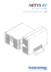
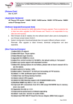
http://www.socomec.com/
User Guide
Revision 0.3, 28 February 2006
2AZ03R03.PDF
AT, IBM are registered trademarks of International Business Machines Corporation.
DOS, Windows 95 / 98 / ME and Windows NT4.0 / 2000 / Xp are registered trademarks of
Microsoft ™ Corporation.
Java and all Java-based marks are trademarks or registered trademarks of Sun Microsystems, Inc. in
the U.S. and other countries.
All other trademarks belong to their respective proprietors.
CHAPTER 1 : UNI VISION OVERVIEW __________________________________________________________ 3
Functions _____________________________________________________________________________
Features ______________________________________________________________________________
System Application ______________________________________________________________________
Users _________________________________________________________________________________
UPS Compatibility List ___________________________________________________________________
3
3
5
6
6
CHAPTER 2 : UNI VISION INSTALLATION _______________________________________________________ 7
JRE / JDK Installation ___________________________________________________________________ 7
Windows O.S.’s Installation Procedure ______________________________________________________ 9
Linux O.S.’s Installation Procedure ________________________________________________________ 10
CHAPTER 3 : UNI VISION BASIC SETTINGS AND STARTING ________________________________________ 11
Procedures ___________________________________________________________________________
UNI VISION Configuration ______________________________________________________________
“univision.cfg” explanation ______________________________________________________________
Starting UNI VISION ___________________________________________________________________
UNI VISION and Netys PR range__________________________________________________________
Starting UNI VISION automatically ________________________________________________________
11
11
16
19
21
21
CHAPTER 4 : ACCESSING UNI VISION VIA WEB BROWSER ________________________________________ 22
Connecting To UNI VISION ______________________________________________________________
UNI VISION Home Page ( Administration )__________________________________________________
UPS Monitor__________________________________________________________________________
Java Applet Monitor ____________________________________________________________________
UPS Management ______________________________________________________________________
UPS History __________________________________________________________________________
Prg Parameters________________________________________________________________________
Shutdown phases description _____________________________________________________________
e-mail Configuration____________________________________________________________________
e-Mail Receivers _______________________________________________________________________
UNI VISION Home Page ( Viewer ) ________________________________________________________
22
24
25
27
31
41
46
48
50
53
56
APPENDIX A : SERIAL CABLE SPECIFICATION__________________________________________________ 60
Netys UPSs ___________________________________________________________________________ 60
All others UPSs________________________________________________________________________ 61
Possible Communication Problems ________________________________________________________ 62
APPENDIX B : USB CABLE NOTES ___________________________________________________________ 63
APPENDIX C : UNI VISION SPECIAL CONFIGURATIONS AND COMMANDS _____________________________ 64
Procedures ( for Windows™ Operating Systems) _____________________________________________
Warning Messages _____________________________________________________________________
Shutdown Procedure for Windows NT4.0 and 2000 ____________________________________________
Shutdown Commands for Windows™ 95, 98, Me______________________________________________
Shutdown Procedure for Windows XP and 2003 ______________________________________________
List of Modifiable Files__________________________________________________________________
Javaw _______________________________________________________________________________
2
64
64
65
66
66
67
67
Chapter 1 : UNI VISION Overview
Functions
UNI VISION is a Java based software that can communicate, get the status, send
commands and monitor the UPS connected to the computer where it is running.
UNI VISION also provides the local computer shutdown in case of a Mains Failure
condition, Low Battery condition, UPS Overload condition, UPS Over-Temperature
condition, and Imminent Stop condition. All shutdown events can be set by the User.
The shutdown software will proceed to perform the automatic shutdown to prevent an
abnormal Server shut-off.
Features
Server connection through RS 232C connector, TCP/IP tunnelling, or USB
The server is connected to the UPS via serial cable, TCP/IP (*) or USB (**).
(*) (**) – Only for enabled UPSs (refer to the UPS user manual for further details)
(**) – Only for Microsoft Windows™ platform.
UPS management
It is possible to monitor and manage the UPS.
Local and Remote UPS monitoring via HTTP and JAVA applets
It is possible to monitor the UPS status using HTTP internet Browser and Java
applets.
Local automatic shutdown
UNI VISION provides automatic shutdown in case of alarm condition when preprogrammed(*).
(*) – Not all conditions are available for all UPSs (refer to the UPS user manual for
further details)
Shutdown scheduling
UNI VISION provides the possibility to perform a scheduled shutdown to permit the
shutdown and restart of the load at pre-set times.
3
Events & measures log
UPS power events, power quality, UPS status and battery condition information are
stored by the software in a log file.
E-mail notification in case of alarm
UNI VISION can send e-mail notification up to 8 different addresses at the same
time in case of alarm (*).
(*) – Not all conditions are available for all UPSs (refer to the UPS user manual for
further details)
Java Technology based
UNI VISION is a Java application that can be run on almost all operating systems
after the installation of the appropriate Java Runtime Environment.
4
System Application
UNI VISION accesses the UPS through an RS 232 interface, TCP/IP tunnelling(*) or
USB(*).
(*) – If supported by the UPS.
Using a Web Browser, you can monitor a UPS, send it commands and
configure certain modes of behaviour of UNI VISION according to your needs.
UNI VISION system have been tested on :
-
Microsoft Windows™ 2000,2003, Xp
Linux kernel 2.4 or superior
on Intel architecture
on Intel architecture
5
Users
Users can also access UNI VISION to see the UPS status, but they access it in read
only mode, so they can not modify UNI VISION settings or send commands to the
UPS.
UNI VISION can be configured remotely by the administrator only if the IP address of
the computer used for remote administration has been properly configured (see
Chapter 3)
Figure 1-1 UNI VISION working-principle diagram
UPS Compatibility List
UNI VISION is compliant with Socomec Sicon UPSs until 6KVA of power.
6
Chapter 2 : UNI VISION Installation
JRE / JDK Installation
UNI VISION is based on Java Technology so you need to have the Java Runtime
Environment (JRE) or the Java development kit (JDK) already installed on your
operating system to run UNI VISION.
Note : If JDK or JRE are not already installed on your operating system please take
time to do it, otherwise UNI VISION will not be able to start.
If you need to know if the JRE or JDK are already installed on your Operating System
or after you have installed the JRE (or the JDK) you want to test if the installation was
completed successfully, you can open a command shell and type the command :
“java –version”
at the command shell prompt.
A text similar to the following confirms the Java environment is already present on your
system :
java version "1.x.x"
Java(TM) 2 Runtime Environment, Standard Edition (build 1.x.x)
Java HotSpot(TM) Client VM (build 1.x.x, mixed mode)
see Figure 2.1,
7
Figure 2.1 JRE, Version Request Command And Answer
Note : If you need the JRE installation file, you can download it from Sun
Microsystems web site or from your operating system producer’s web site.
JRE for some Operating Systems (Windows ™ and Linux) could be available on UNI
VISION web site.
Note for Linux users :
If you are manually installing the JRE, it should be installed using default paths (see
the list below) to permit start scripts “start.sh” prepared for each operating system to
find the JRE, otherwise if you need or you prefer to install JRE in a different path,
please remember to modify the start.sh script in the UNI VISION folder according to
the path you chose.
LINUX
"/opt/jre/bin"
JRE Suggested version : 1.5 for full support of the swing libraries in order to
have optimal graphical appeal. The minimal requirement is JRE 1.4
8
Windows O.S.’s Installation Procedure
Mode 1 : Uncompressing the ZIP archive
You can download UNI VISION from the company web site in the format of a
compressed zip archive. Extract it in a folder of your hard disk.
Note :
a) We suggest to decompress the contents of the file in the root directory (C:\)
(however it is also possible to use a different folder name if you prefer).
b) The USB management won’t be available. You need to install the package
using InstallUniVision.exe
Mode 2 : run the InstallUniVision.exe (windows setup)
You can find InstallUniVision.exe, like the zip archive, in the Uni Vision web site.
In both cases ( mode 1 or 2 ) after you have decompressed or installed the SW you will
obtain a folder structure like that shown in Table 2.1.
Directories and files
.
..
httproot
httproot\1 to httproot\7, httproot\applet, httproot\images,
httproot\html
config
config\1 to config\7, config\cgi, config\htm
activation.jar
comm.jar
javax.comm.properties
jspComm.jar
Serialio.jar
mail.jar
mailapi.jar
servlet.jar
shutdown.exe
shutdown_syntax.htm
smtp.jar
start.bat
univision.cfg
univision.jar
ss_usb_ups.dll
win32com.dll
Table 2.1 UNI VISION Windows Files and Folders List
The installation phase is completed, please refer to chapter 3 for the configuration
procedure.
9
Linux O.S.’s Installation Procedure
You can download UNI VISION from the web site as a compressed file. Decompress it
into a temporary directory .
Launch the installation script using the following syntax :”./INSTALL.SH”.
You will be prompted to type the name of your Operating System so the installation
can copy the right files needed by UNI VISION in the standard path.
If you want to install UNI VISION in a different folder from the standard one you have
to modify the installation script.
Note : to perform the installation you must login as root user.
After you run the installation script you will obtain a folder structure like that shown in
Table 2.2.
Directories and files
./
../
config/
config\1 to config\7, config\cgi, config\htm
httproot/
httproot\1 to httproot\7, httproot\applet, httproot\images,
httproot\html
lib/
activation.jar
custom.sh*
httpServer.log
jspComm.jar
mail.jar
mailapi.jar
msg.sh*
Serialio.jar
servlet.jar
shutdown.sh*
smtp.jar
start.sh*
univision.cfg
univision.jar
Table 2.2 UNI VISION Unix Files and Folders List
The installation phase is completed, please refer to chapter 3 for the configuration
procedure.
10
Chapter 3 : UNI VISION Basic Settings and Starting
Procedures
UNI VISION Configuration
Using the Graphical Utility
a) After the installation, the first action you have to do is to configure the computer
“communication interface” (serial/usb), and the other fundamentals parameters. To
do that, launch the graphical interface (GUI) and follow the instructions explained in
the following lines:
Windows ™
: start.bat (if installed following Mode 1) or click in the Start>Programs->Uni Vision->univision (if installed following Mode 2
instructions ).
Linux
: ./start.sh
b) Open the “SW Setup page” : communication
UPS protocol type :
- JBUS-PH for Netys PE-PL
- JBUS-P for all others
Selected Interface :
- <serial interface>
- ETH (Ethernet Link) (*)
- USB (*)
(*) If supported by the UPS
RS-232 speed :
Tipically 2400 for JBUS-PH, 9600 for
JBUS-P
UPS TCP/IP Port/Address :
The address and port of the UPS
supporting the TCP/IP tunnelling
Local UPS autodiscover :
Useful to find on which interface (RS232 or
USB) the UPS is connected to.
11
Note : pay attention to the serial port naming depending on the O.S. in use
Operating System
Standard first serial port name
Windows
Linux
com1
/dev/ttyS0
Table 3.1 Serial port names
Change the parameters only if necessary according to your needs.
c) “SW Setup page” : server parameters
History Blind time:
The program starting period time during which
events are not stored in the log file
(recommended not less than 20 seconds).
Local history log file :
Size in Kbytes of ½ every log type (see the
complete explanation below)
Http server port :
The TCP/IP port used by the HTTP server to
exchange information with the browser.
Web browser command :
The command to start your web browser. With
starter.exe (Windows only) the HTML pages
are opened using your default browser.
Specify <path>\<web browser> in case you
use another application.
Change the parameters only if necessary according to your needs.
12
d) “SW Setup page” : security
Remote Manager IP address n (1-8):
This parameter defines the IP address(es) of
the computer(s) used as management station
to configure the UNI VISION parameters.
Note: the IP address of the machine where
Uni Vision is running is automatically a
“manager IP” one. No need to add it to the
list.
(see below for further details)
Change the parameters only if necessary according to your needs.
e) “SW Setup page” : language
It is possible to select the language of the
“Viewer HTML interface” ONLY.
Chose one of the 6 languages available.
In case you need a custom one, click on the
related button and make yourself the
translation
(see step (F) )
Note : the language changing will be effective next time the sw is started
Change the parameters only if necessary according to your needs.
f) “SW Setup page” : custom language
It is possible to load a “custom” language
file from a local/network resource.
Warning: the file needs to be correctly
formatted.
The file is saved in the following path:
<uni vision path>\config\7\str0.t
Manually modifying the univision.cfg file
13
The GUI utility ( see previous paragraph ) read/save data from the univision.cfg file.
If you prefere, it is possible to manually modify the configuration file using a text editor
(see figure 3.1 below), and following the same instructions given in the previous
section.
Figure 3.1 Example of univision.cfg ProtocolInterface configuration
Connect Uni Vision and the UPS
After the configuration of the serial port you have to connect the serial cable (or USB if
supported ) between the UPS connector (RS232 or USB) and the computer serial port
or USB (see Figure 3.2). Mind NOT to mix interfaces USB needs to be connected to
USB or RS232 to RS232. Refer to the UPS user manual to learn which interfaces
is/are supported. In any case, if the UPS is shipped with its own cable, it is strongly
recommended to use that cable instead of any other in your possession.
If you set the wrong communication interface in the configuration file, the Admin HTML
Interface will show “UPS Off” in the UPS Status field and “Unknown” in other fields of
the UPS Comprehensive view window (see Figure A.2 in Appendix A chapter).For the
same reason Viewer HTML Interface will show “measure not available”
14
Figure 3.2 RS232 Serial Cable connection
Notes (a) :
• Please refer to Appendix A for the serial cable specifications.
• As some computers have more than one serial communication port, please
be sure you have configured the right one in the “univision.cfg” file.
• No more than one UPS can be simultaneusly managed by Uni Vision on the
same PC.In particular with USB (if supported by the UPS) only the first UPS
answering to a “device discovery procedure” will be considered connected.
If other UPSs are plugged to the same PC, they will be ignored.
Note (b) : since UNI VISION uses internet Web pages in order to show information,
please ensure you’ve already installed the TCP/IP protocol on your
Operating System, otherwise you must install it before running UNI VISION.
For information about how to install and set up the TCP/IP protocol, please
refer to your Operating System manual.
15
“univision.cfg” explanation
(integration of what explained in Using the Graphical Utility)
UNI VISION has some configuration files that can be used to tune its behaviour.
The first configuration file that may need to be modified is “univision.cfg”; changing the
contents of this file you can define some program parameters.
This paragraph explains the meaning of each row of univision.cfg file.
HttpServerPort = 8080
This parameter defines the TCP/IP port used by the HTTP server to exchange
information with the browser.
ProtocolInterface = [parameter]
This parameter defines the serial port used by the computer to exchange information
with the UPS, please refer to Table 3.1 to know the name of the serial port of your O.S.
NOTE:
If the parameter is set to ETH, the communication between the UPS and the computer
running Uni Vision will be through the TCP/IP (on Ethernet) connection.
This option disable the RS-232/USB communication interface and enable two new
specific parameters which must be set properly:
• ProtocolNodeAddr = <UPS IP address>
• ProtocolPort = <TCP/IP port used for JBUS tunnelling (def. =1025)>
This parameter is available only for those UPSs with JBUS protocol over TCP/IP.
If the parameter is set to USB, the communication between the UPS and the computer
running Uni Vision will be through the USB port.
This parameter is available only for those UPSs with JBUS-PH protocol over USB
interface.
ProtocolSpeed = 9600
This parameter defines the speed of the serial communication. It can be modified but
only according to the communication speed used by the UPS.
If speed is set above 9600, it is not guaranteed the communication works properly.
This parameters doesn’t care in case of TCP/IP connection (see ProtocolInterface
parameter).
ProtocolSpeedJBUS-P = 9600
Default speed for a UPS with JBUS-P protocol
ProtocolSpeedJBUS-PH = 2400
Default speed for a UPS with JBUS-PH protocol
16
ProtocolType=JBUS-PH
Protocol used to communicate between the UPS and the PC (it can be JBUS-P or
JBUS-PH)
HistoryBlindTime = 60
This parameter defines the program starting period time during which some spurious
events should not be logged in the log file.
The value of this parameter could be decreased minimum to 20 sec if needed.
Language = 1
The language index used by the “Viewer HTML interface” (1=English)
DefaultBrowserCommand=starter.exe
The command to start your web browser. With starter.exe (Windows only) the HTML
pages are opened using your default browser. Specify <path>\<web browser> in case
you use another application.
LogSize = 25000
This parameter defines the dimension of the log files in bytes. Since there are 2 log
files for each of the 3 log types available in UNI VISION in order to create a circular
buffer of information, the real dimension of the whole log file could be double of the
value specified by log size parameter (see Figure 3.3).
With the default value it is possible to log about 6 hours of measures.
For SW Events History and UPS Events History depends on the quantity of events
occurred.
Figure 3.3 UNI VISION log files scheme
17
AdminAddress_0 = 127.0.0.1
This parameter defines the IP address(es) of the computer(s) used as management
station to configure the UNI VISION parameters.
More than one address can be inserted if you want to enable more than one computer
to be able to change UNI VISION parameters, to do this you need to have more rows
with different indexes and IP addresses :
AdminAddress_1 = 172.17.10.1
AdminAddress_2 = 192.168.7.10
AdminAddress_3 = 172.17.10.4
Only IP addresses are accepted for AdminAddress_x parameters : it is not possible to
specify the name of the computer(s) which will be used to configure UNI VISION
instead of its(their) IP address(es).
If a bad parameter is specified, UNI VISION gives a notification by the standard output
screen (the shell window used to start the program) “Wrong format for remote address
... please check”.
Maximum 8 different address indexes are allowed.
Warnig note : the computers with the IP addresses specified in the list can access
Uni Vision and change the configuration or send direct commands i.e.
the shutdown command.
This can cause security problems.
Note for Microsoft O.S.s : if you specify 127.0.0.1 or “localhost” as address for
accessing Uni Vision web pages, the CPU load can be very
high; because of this, it is better to use the real IP address
in both the univision.cfg file and in the browser’s address
field.
All the modifications made take effect once UNI VISION is re-started.
18
Starting UNI VISION
Using the Graphical Utility
In order to start-up UNI VISION you can simply move to the UNI VISION folder, and
run the “start” file both from graphical interface or from text interface (like you’ve done
to configure it).
If you’ve installed it under Windows using InstallUniVision.exe, you can start the
program using the START menu and selecting the Uni Vision folder.
Figure 3.4 Starting UNI VISION : start
This will simply execute a command in order to start the Java environment and run UNI
VISION. With the standard start.bat/start.sh script the graphical interface will be shown
( note that Uni Vision is in not communicating yet with the UPS ).
Press the [Start Uni Vision] button
SUCCESS
FAILURE (*)
(*) Tipically when the RS232 interface does not exist!
Figure 3.5 Running UNI VISION : success / failure
19
Figure 3.6 Running UNI VISION : execution on a command shell
If the SW is opened using the start.bat/start.sh script, the command shell shows
information about the operations executed by the Java environment, confirming UNI
VISION has been started and it is working correctly (see Figure 3.6).
Note (a) : For Windows™ Operating Systems
Uni Vision launched with start.bat:
If you don’t want to have an open command shell window while UNI VISION
is running, please refer to the “Javaw” paragraph in Appendix B.
If you are not using the “Javaw” command to start UNI VISION, the
command shell window must remain open, otherwise the program will be
closed.
Uni Vision launched from [START] menu:
The shell won’t be available
Note (b) : For Unix Operating Systems
If you don’t want to have an open command shell window while UNI VISION
is running, please use a “&” character at the end of the command line.
Note (c) : the Operating System will have this behaviour only if you are the
Administrator user on Windows™ O.S.’s, and root user on Unix O.S.’s.
It is also possible to modify the start file in order to adapt it to your needs, see
Appendix B for UNI VISION Special Configurations.
When you see the “UNI VISION is running” message in the command shell you can
start the Web Browser i.e. Internet Explorer, Netscape Navigator, Konqueror etc. and
type the IP address or the name of the computer in which UNI VISION is running to
access to its web pages (it is also necessary to specify the http server port number.
See the following pages in this chapter for deeper details) .
Example:
http://192.168.7.20:8080
20
UNI VISION and Netys PR range
If the connected UPS is a Netys PR, the following graphical interface should appear :
Checking Enable UPS setup
the combo boxes to configure
your UPS Netys PR will be
enabled.
By selecting one from the
proposed values from the
drop-down list, you’ll be able to
set the following parameters:
- Output voltage
(220-230-240)
- Input Mode
(Normal-Wide)
- Battery Extension
(0-1-2)
Warning : refer to the UPS user manual for other details regarding possible parameters
configuration.
Mind that a wrong configuration could result in damages and/or loss of data.
It is strongly recommended to unplug any load from the UPS output while changing the
“Output voltage”.
Output Voltage:
the default setting is 230Vac but it is possible to select 220 or 240Vac according the
application environment. This parameter set the output voltage in battery mode and
also the input range voltage windows for AVR (Automatic Voltage Regulator)
intervention.
Input Mode:
the default setting is Normal but it is possible to select Wide mode operation according
the application environment. This parameter set the low input range voltage threshold
for AVR intervention. The minimum input voltage move from 184V to 154V refer to
230Vac nominal setting. Changing this parameter the output regulation with mains
present changes from –10/+10% (Normal mode) to –20/+10% (Wide mode).
Battery Extension:
the default setting is 0 that means no extra battery present. This parameter set the
additional battery +1 or +2 available for some models to extend the autonomy. The
right setting assure the correct autonomy indication.
Starting UNI VISION automatically
Modify the start.bat or start.sh script file, adding a parameter as explained in the
following lines:
java -cp %CLASSPATH%;servlet.jar;comm.jar;univision.jar;activation.jar;mail.jar;mailapi.jar;smtp.jar;.
UniStart -s
(with –s the SW starts automatically and without any graphical interface )
java -cp %CLASSPATH%;servlet.jar;comm.jar;univision.jar;activation.jar;mail.jar;mailapi.jar;smtp.jar;.
UniStart -x
(with –x the SW starts automatically with the graphical interface )
21
Chapter 4 : Accessing UNI VISION via Web Browser
Connecting To UNI VISION
When UNI VISION starts, it launches a HTTP server in order to allow users to access
the UPS.
You may receive this error message, if the command shell is open:
Error detected opening the HTTP socket: 8080.
Change the [HttpServerPort] value inside the univision.cfg.
This is due to the fact that another HTTP server is already running on port 8080, so
you need to assign another port number in the univision.cfg file, i.e. 8085 or another
free port.
To access UNI VISION, you have to specify the IP Address of the computer where UNI
VISION is running and the port number in the Browser Address Field to access the
UPS.
From local computer and using the graphical interface:
22
From local computer and manually typing the address in the browser address field:
•
•
Admin HTML Interface : type “http://127.0.0.1:<port number>” or
“http://localhost:<port number>”.
Viewer HTML Interface : type “http://127.0.0.1:<port number>/Index.htm” or
“http://localhost:<port number>/Index.htm”.
Note for Microsoft O.S.’s : if you specify 127.0.0.1 or “localhost” as address for
accessing Uni Vision web pages, the CPU load can be very
high; because of this it is better to use the real IP address in
both the univision.cfg file and in the browser’s address field.
23
UNI VISION Home Page ( Administration )
Below you can see the UNI VISION main page. This page gives a comprehensive view
of the most important UPS information.
Figure 4.1 UNI VISION Main Page
Note (a) : at the bottom of each page you can find two buttons, Back and Help.
The Back button will move you to the page displayed previously.
The Help button will open a new page containing a brief explanation of the
meaning of each item present in the page where you press the Help button.
Note (b) : Some menus could be hidden because they are not compatible with the
UPS model you are using; this is the normal behaviour of UNI VISION.
24
UPS Monitor
UPS Monitor is a macro-menu that can be selected to access some sub-menus.
Comprehensive View
This page (the same as the UNI VISION main page), gives a snapshot of all the main
UPS parameters (see Figure 4.2).
The page is refreshed automatically so you don’t need to request a manual refresh to
update the UPS information.
Figure 4.2 UNI VISION UPS Monitor Menu
Selecting the button
you access the graphic mimic panel of the UPS (Java
Applet Monitor).
See the section entitled Java Applet Monitor in this chapter for a description.
25
UPS Identification
Select “UPS Identification” in the “UPS Monitor” menu to view a page containing UPS
and UNI VISION Identification parameters.
UPS Battery
Select “UPS Battery” in the “UPS Monitor” menu to view a page containing the UPS
battery parameters.
The possible battery states are:
Low Battery
Battery failure
Battery discharging
Battery OK
UPS Input
Select “UPS Input” in the “UPS Monitor” menu to view a page containing the UPS input
block parameters.
Note : One column will be displayed for a Single / Single, three columns will be
displayed for a Three / Single or a Three / Three-phase UPS.
UPS Output
Select “UPS Output” in the “UPS Monitor” menu to view a page containing the UPS
output block parameters.
Note : One column will be displayed for a Single / Single and a Three / Single-phase
UPS, three columns will be displayed for a Three / Three-phase UPS.
Alarm Table
Select “Alarm Table” in the “UPS Monitor” menu to view a page containing the UPS
current alarms.
26
Java Applet Monitor
The button
in the “UPS Monitor” “Comprehensive view” gives access to the UPS
graphic mimic panel (Java Applet Monitor).
UNI VISION provides a real-time Java Applet in order to display the UPS status.
This applet displays in real time the most important UPS parameters:
AC Input Voltage,
AC Output Voltage,
UPS Load,
Battery Capacity,
In/Out frequency (if available)
The Java Applet comprises different areas:
-a Status Bar displaying the current UPS status
-the Mimic Panel Image
-an Alarms Box displaying the codes of the current UPS alarms
-a Parallel Bar indicating the presence of UPS parallel modules
-the Measures Area displaying graphically the most important UPS measures.
Mimic Panel Image
Alarm Box
Function Buttons
Parallel Bar
Status Bar
Measurements Area
Figure 4.3 UNI VISION UPS Java Applet Monitor
27
Function Buttons
Function Buttons are used to modify the Applet behaviour, below you can see a
description for each one of them.
Display switch
–This button is used to switch the display
from measurement mode to graphic
mode and vice versa.
Pop-up switch
– This button is used to enable and disable
display of the warning messages.
Polling interval configuration
– This button is used to set the time
between two data retrival from the UPS.
Exit
– This button is used to exit the Java
applet monitor.
Status Bar
The icons in this bar may change colour to report an alarm condition of the UPS.
Mimic Panel Image
This image may change the colour of each of its blocks to report an alarm condition of
the UPS according to the status bar icons.
28
Alarms Box
This box gives the codes of active alarms on the UPS according to the indications in
Table 4.1.
Whether the alarms shown are managed or not depends on the UPS model; as a
result, some alarms may be displayed on some UPS models, and not on other models
(see your UPS manual for further information).
Parallel Bar
It is used to show the presence of up to 6 UPS modules (maximum 4 for Modulys
UPS) in parallel.
If a module is present the corresponding icon is coloured in green when operating
normally and red if there is an operating problem.
Measures Area
In this area you can see some diagrams reporting the principal measures regarding the
UPS.
29
Alarm Codes
CODE
A00
A01
A02
A03
A04
A05
A06
A07
A08
A09
A10
A11
A12
A13
A14
A15
A16
A17
A18
A19
A20
A21
A22
A23
A24
A25
A26
A27
A28
A29
A30
A31
A32
A33
A34
A35
A36
A37
A38
A39
A40
A41
A42
A43
A44
A45
A46
A47
A48
A49
A50
A51
A52
A53
A54
A55
A56
A57
A58
A59
A60 ÷ A63
Description
Alarm present (OR of all UPS alarms)
Battery failure / Battery anomaly / Battery fuse open
UPS overload
Output voltage out of tolerance
Digital power supply fault (Vcc)
Input voltage out of tolerance
Auxiliary mains out of tolerance
Inside over-temperature alarm (OR of all temperature sensors)
Manual By-pass closed
Short-circuit detection on UPS output
Battery charger failure
Inverter over-current
Excessive Inverter distortion
Precharge voltage out of tolerance
BOOST output voltage too low
BOOST output voltage too high
Battery voltage too high
Improper condition of use
Overload timeout blocking Inverter
Microprocessor control system failure
Configuration data map corrupted
PLL Fault
Input mains general alarm
Rectifier general alarm
BOOST general alarm
Inverter general alarm
Battery charger general alarm
Output voltage over limits
Output voltage under limits
By-pass general alarm
UPS stopped for overload
Imminent Stop
Module 1 in parallel general alarm
Module 2 in parallel general alarm
Module 3 in parallel general alarm
Module 4 in parallel general alarm
Module 5 in parallel general alarm
Module 6 in parallel general alarm
External Alarm 1
External Alarm 2
External Alarm 3
External Alarm 4
E-Service General Alarm
Redundancy Lost
Maintenance Alarm
Transfer locked alarm
Transfer blocked in bypass alarm
Battery room alarm
Manual bypass alarm
Battery discharged
Insufficient resources
ACS Alarm
Rectifier fault
Boost fault
Inverter fault
Parallel fault
Generator set general alarm
Generator set fault
Emergency STOP
Battery Circuit open
FREE
Table 4.1 Alarm Codes
Note : Some of the alarms described in Table 4.1 may not be supported by all UPS
ranges.
30
UPS Management
UPS Management is a macro-menu that can be selected to access some sub-menus.
Figure 4.4 UNI VISION UPS Configuration Menu
UPS Configuration
Select “UPS Configuration” in the “UPS Management” menu to view a page containing
the UPS nominal input and output voltage and frequency values (see Figure 4.4).
UPS Control
Select “UPS Control” in the “UPS Management” menu to view a page containing the
list of direct commands you can send to the UPS (see Figure 4.5).
Below you can see the list of commands you can send to the UPS (some items will be
present only if the features are supported by the UPS).
Stand-by Mode Enable
Stand-by Mode Disable (UPS On)
Eco-Mode Enable
Eco-Mode Disable
Alarms Reset
Reset Commands
Buzzer Off
Send
Immediate UPS switch-Off command.
Immediate UPS switch-On command.
Enable Eco-Mode function.
Disable Eco-Mode function.
Resets active alarms (also overload and overtemperature alarms).
Resets pending commands
Switches off UPS buzzer (in case of another alarm
the buzzer will switch on).
When this button is pushed, the software sends the
selected command to the UPS.
31
Figure 4.5 UNI VISION UPS Control Menu
Power Share Plugs :
With the Power Share Plugs check box(es), you can force the power share plug(s)
open (not checked ) or closed (checked) quite immediately.
The Power Share Plugs item will be present only if this feature is supported by the
UPS.
Set :
The Set button sends the selected command to the UPS.
Warning : these commands are sent to the UPS immediately, without any warning
message.
Please pay attention while accessing this menu.
32
Power Share Management
The menu will be present only if the feature is supported by the UPS.
The UPS can have up to 4 power plugs.
The power plugs are programmable outlets that can vary their output behaviour as the
user decides.
This menu lets you configure the behaviour of the output plugs (see Figure 4.6).
Available Plugs :
Lists the Active Plugs. If a plug is not available, the related line is hidden.
Mode :
Management Off :
The automatic plugs management is disabled.
Remaining Battery Capacity Management :
The output power plug will be switched off when the Battery Capacity is lower than the
set value (1 to 99%). This feature is managed by the UPS.
Remaining Backup Time Management :
The output power plug will be switched off when the Remaining Backup Time is lower
than the set value (1 to 120 minutes).
This feature is managed by the UPS.
Emergency Light :
In case of mains failure, the UPS closes the plug(s) to supply the emergency lights.
When the power is restored, the plug will be opened (no value setting).
This feature is managed by the UPS.
Value :
Value used to manage the power share plugs.
33
Set Value :
When this button is pushed, UNI VISION sends all the active plugs management
configuration to the UPS.
Figure 4.6 UNI VISION Power Share Menu
Shutdown Parameters
Select “Shutdown Parameters” in the “UPS Management” menu to view a page
containing a table with the shutdown delays for each of the events reported below.
AC Failed:
Battery Low:
UPS Overload:
UPS Over Temperature:
Imminent Stop:
Weekly schedule
Special Day Schedule
Mains power supply fault
Low battery charge remaining
Output overload
UPS internal overheating
UPS imminent stop alarm
Weekly scheduled switch-on / switch-off of the load
Scheduled switch-on / switch-off of the load
This menu lets you modify the parameters associated with the shutdown events (see
Figure 4.7).
Some items will be present/executed only if the features are supported by the UPS.
34
Ups Shutdown Delay :
It defines how many seconds after starting the shutdown procedure, the UPS will be
turned off. (see the red area + the green area of the graphic in Figure 4.16).
UPS Shut Off :
It defines if the UPS load will be turned off (stand-by) or not, after the completion of the
shutdown procedure on servers.
Apply :
It confirms the values set in the UPS Shutdown Delay and UPS Shut Off fields.
Shutdown Event :
The list of all events that may require the shutdown of the UPS, and also the shutdown
of the load supplied by the UPS (i.e. a Server).
Action :
The drop down list where you can select if the related event should be monitored or
not; if this setting is “Disable”,and the related event occurs, the program will take no
action.
Delay :
Delay time in minutes before system shutdown in case the event occurs (see the blue
area of the graphic in Figure 4.16).
1st Warning :
Delay time of 1st warning message in case the event occurs.
35
Warning interval :
Interval before repeating Warning Messages.
After the 1st Warning, successive warnings will be given with this interval.
This will continue until the completion of the total delay time for shutdown.
Set Value :
When this button is pushed, UNI VISION saves all shutdown events settings.
Figure 4.7 UNI VISION Shutdown Parameters Menu
Note : the UPS will be switched off by the program only in case of mains failure or
scheduled shutdown.
In case of another alarm condition, the program lets the UPS to manage its
shutdown, and the possibility to set the shutdown time for this kind of events is
only intended to perform the computers shutdown (the program has no effect
on the UPS shutdown procedure).
36
Weekly Schedule
The menu will be present only if the feature is supported by the UPS.
Select “Weekly Schedule” in the “UPS Management” menu to view a table containing
the weekly scheduled shutdown days and times.
You can modify this table according to whether you need to supply the UPS load or
not.
Figure 4.8 UNI VISION Weekly Schedule Menu
Index :
This column provides a reference number for the configured shutdown / restart events.
Shutdown Day, Restart Day :
The drop down list where you can select a day of the week to switch-off / supply the
load.
Shutdown Time, Restart Time :
The field where you can insert the hour of the day to switch-off / supply the load.
Set Value :
When this button is pushed, UNI VISION saves all schedule table settings.
37
Weekly Scheduling Rules
The scheduling table needs to be set following some rules i.e. it does not accept the
overlapping of the scheduled periods; below you can see the rules applied by UNI
VISION to accept the scheduling.
Applied rules :
1) Both "Shutdown Day" and "Restart Day" must be ENABLED to engage the event.
Otherwise the data record is accepted but it is NOT working.
2) "Shutdown Day" & Time and "Restart Day" & Time must differ by at least 1 min from
each other (*)
3) The standby periods cannot be overlapping (**)
4) Events that are pending at the program start-up are automatically discarded.
5) Events that become pending at the very moment they are configured are
automatically discarded.
6) Events that don't produce shutdown because initially DISABLED in "Shutdown
Parameters" are automatically discarded if ENABLED while they are pending.
(*) - Note that the Min_off sent to the UPS is calculated with this formula
[Scheduler OFF period in min] - Delay (Min) - UPS SD Delay / 60
If the resulting number is < 1 minute, the standby is NOT SENT.
(**) - The user is informed with a popup warning message in case of misuse. Note that
this control is performed only if rule (1) is applied. Furthermore, one range period is
considered overlapping with another even if their Start/End Date & Time are equal to
that of another range period (see Figure 4.8b).
Figure 4.8b UNI VISION Weekly Schedule Warning Message
38
Special Day (Schedule)
The menu will be present only if the feature is supported by the UPS.
Select “Special Day” in the “UPS Management” menu to view a table containing the
special days scheduled shutdown days and times.
You can modify this table according to whether you need to supply the UPS load or
not.
Figure 4.9 UNI VISION Special Day Schedule Menu
Index :
This column provides a reference number for the configured shutdown / restart events.
Shutdown Date, Restart Date :
The field where you can insert a date to switch-off / supply the load.
Shutdown Time, Restart Time :
The field where you can insert the hour of the day to switch-off / supply the load.
Set Value :
When this button is pushed, UNI VISION saves all schedule table settings.
39
Special Day Scheduling Rules
The scheduling table needs to be set following some rules i.e. the scheduling dates
must be inside a certain interval; below you can see the rules applied by UNI VISION
to accept the scheduling.
Applied rules :
1) Both "Shutdown Date" and "Restart Date" different from 01/01/1970 to engage the
event.
Otherwise the data record is accepted but it is NOT working.
2) "Shutdown Date & Time” must differ by at least 1 minute compared with "Restart
Date" & Time. (*)
3) The standby periods cannot be overlapping (**)
4) Limits : the date range is limited between 1/1/1970 to 31/12/2100.
5) Events that are pending at the program start-up are automatically discarded.
6) Events that become pending at the very moment they are configured are
automatically discarded.
7) Events that don't produce shutdown because initially DISABLED in "Shutdown
Parameters" are automatically discarded if ENABLED while they are pending.
(*) - Note that the Min_off sent to the UPS is calculated with this formula
[Scheduler OFF period in min] - Delay (Min) - UPS SD Delay / 60
If the resulting number is < 1 minute, the standby is NOT SENT.
(**) - The user is informed with a popup warning message in case of misuse. Note that
this control is performed only if rule (1) is applied. Furthermore, one range period is
considered overlapping with another even if their Start/End Date & Time are equal to
that of another range period (see Figure 4.9b).
Figure 4.9b UNI VISION Weekly Schedule Warning Message
40
UPS History
UPS History is a macro-menu that can be selected to access the log sub-menus.
This information is contained in some files in the “httproot” subfolder and is updated
while the program is running.
Figure 4.11 UNI VISION UPS History Menu
Measure History
Select “Measure History” in the “UPS History” menu to view a page containing the log
of all measures of the UPS (see Figure 4.11).
The information contained in the table could be saved as a standard CSV format file by
simply clicking ( with the right mouse button ) on the “Download” link at the bottom of
the page.
41
Date :
The day when the measures were saved in the history log file.
Time :
The hour and minute when the measures were saved in the history log file.
Output Load :
The percentage of load for the UPS output, if the UPS is a Three / Three phase, the
load percentage of each phase will be displayed.
Auxiliary Mains Star Voltage :
The value in volts of the input mains voltage at recording time, if the UPS is a Three /
Three phase, the information about each phase will be displayed.
Output Star Voltage :
The value in volts of the UPS output voltage at recording time, if the UPS is a Three /
Three phase, the information about each phase will be displayed.
Battery Capacity Remaining :
The estimated value as a percentage of the remaining battery capacity
Auxiliary Frequency :
The value in hertz of the input mains frequency at recording time.
42
Figure 4.12 UNI VISION UPS Event History Menu
UPS Event History
Select “UPS Event History” in the “UPS History” menu to view a page containing a log
of all events on the UPS (see Figure 4.12).
The information contained in the table could be saved as a standard CSV format file by
simply clicking ( with the right mouse button ) on the “Download” link at the bottom of
the page.
Date :
The day when the measures were saved in the history log file.
Time :
The hour and minute when the measures were saved in the history log file.
Event Description :
The brief description of the event that occurred.
43
Figure 4.13 UNI VISION UPS Software Event History Menu
SW Event History
Select “SW Event History” in the “UPS History” menu to view a page containing a log
of all events affecting the software (see Figure 4.13).
The information contained in the table could be saved as a standard CSV format file by
simply clicking ( with the right mouse button ) on the “Download” link at the bottom of
the page.
Date :
The day when the measures were saved in the history log file.
Time :
The hour and minute when the measures were saved in the history log file.
Event Description :
A brief description of the occurred event.
44
Note : please see section “univision.cfg” in Chapter 3 for details about log files size.
No Data
If you have just erased the log files from the “programfolder/httproot”(if you have
retained the default folder and extracted the program there), and the program hasn’t
had enough time to recreate them, it may be possible that there is no data available;
in this case, you will see pages similar to those shown in figure 4.14.
Figure 4.14 UNI VISION Event History Menus with no data
45
Prg Parameters
Prg Parameters is a macro-menu that can be selected to access the UNI VISION
configuration pages sub-menus.
The configuration information is contained in the “program.cfg” file in the “config”
subfolder and it is updated while the program is running .
Note : even if the program.cfg file is modifiable with a simple text editor, we strongly
suggest to use UNI VISION Setup page (see chapter 3) and the Admin HTML
Interface (explaned in this chapter).
In this page you can also see the current settings for the shutdown commands,
warning commands and script(s) execution.
Figure 4.15 UNI VISION Parameters Menu
Equipment Description :
In this field you can insert a description (comment) about the UPS.
Reference People :
In this field you can insert the name of the person in charge of managing the UPS.
Shutdown Command :
In this field you can insert the command you may give to the Operating System to
execute the shutdown procedure.
46
Custom Switch-Off Script :
In this field you can insert a script to be executed when the delay time you have set for
a certain alarm is elapsed (this could be used to close some applications before the
shutdown procedure starts. See “Shutdown Parameters” and “Shutdown phases
description” in this same chapter).
Warning Command :
In this field you can insert the command to send a warning message (specific for your
Operating System and/or tailored on your needs). If you erase the content of this field,
the warning messages will only be sent to the standard output (only if the command
shell is visible. See Appendix B for more details and troubleshooting).
Note : the % character (percentage) is a jolly. This means that when the program
detects an alarm condition, it sends a message using the “warning command”
just described substituting the % with the specific alarm description.So, mind not
to delete the %, otherwise the just mentioned “alarm description” won’t be
present in the message itself.
Local Shutdown Delay :
In this field you can insert a delay time in seconds you want / need to wait before
executing the shutdown command on the local server (see the red area of the graphic
in Figure 4.16).
Set Value :
When this button is pushed, UNI VISION stores all the configuration you set in the UNI
VISION configuration file.
Note : all the commands should be inserted using the absolute/complete path.
47
Shutdown phases description
Figure 4.16 UNI VISION Shutdown phases description graphic
The shutdown procedure consists of 3 main phases :
The reversible shutdown phase (1st one)
The NOT reversible shutdown phase (2nd one)
The UPS Shut Off (3rd phase)
1st phase starts after an event i.e. mains failure is detected by the UPS;
at this time the UPS sends the event information to UNI VISION.
According to the time set in “1st Warning” field for the mains failure event in the
Shutdown Parameters Page (UPS Management main menu) a Warning message is
sent using the command set in the Warning Command field (Prg Parameters main
menu).
48
The 1st phase lasts for the time set in “Delay” field for the mains failure event in the
Shutdown Parameters Page (UPS Management main menu).
During this phase after the first warning message, other warning messages are sent
according to the time set in “Warning Interval” field for the mains failure event in the
Shutdown Parameters Page (UPS Management main menu).
If the alarm condition stops i.e. mains restored during the 1st phase, the whole system
returns to the normal “waiting” condition, ending the warning messages sending
procedure and without performing further actions.
If the alarm condition is longer than the set Delay time, UNI VISION enters the 2nd
phase: the NOT reversible phase.
This means after this moment the computer shutdown procedure will become NOT
reversible to ensure correct completion.
During the 2nd phase the Warning messages are still sent until the computer shutdown.
The total duration of the 2nd and 3rd phase is set in the UPS Shutdown Delay field in
the Shutdown Parameters page (UPS Management main menu).
Since at the end of the 3rd phase the UPS should shut off (to avoid the battery damage
due to complete discharging) and stop supplying the load, it is necessary to set a
shorter delay time for computers shutdown (2nd phase).
The 3rd phase ends up with UPS shut off which simply consists stopping supplying the
load and going into UPS stand by condition (waiting for mains restored if this was the
cause of the shutdown or the scheduled time).
Note : the UPS will be switched off by the program only in case of mains failure or
scheduled shutdown.
In case of another alarm condition, the program lets the UPS to manage its
shutdown, and the possibility to set the shutdown time for this kind of events is
only intended to perform the computers shutdown (the program has no effect
on the UPS shutdown procedure).
49
e-mail Configuration
Select “e-Mail Configuration” in the “Prg Parameters” menu to access the e-mail
configuration page where you can set the information necessary for UNI VISION to
send e-mail.
Figure 4.17 UNI VISION e-mail Configuration
SMTP Mail Address Server
In this field you have to insert the address (or the name if you have a DNS server in
your network) of your mail server that should receive and process the e-mail.
SMTP Mail Account
In this field you have to insert the account the program should use to send e-mail.
SMTP Mail Account Password
Use the link in this field to access the e-mail password input page (see Figure 4.18).
Mind that it could be necessary ONLY if your mail server requires authentication.
Note : remember to save the parameters you set in the e-Mail Configuration page
before clicking the link, otherwise because of the normal browsers’ working
method you risk loosing all the data inserted, and then you have to type it in
again.
50
Figure 4.18 UNI VISION e-mail account Password Configuration
On this page you have to insert the password twice for confirmation.
If you make a mistake while typing the password you will be notified by a warning
message and the password field will be blanked to let you retype the password again
(see Figure 4.19).
Figure 4.19 UNI VISION password error notification
You can also decide if you want to store the password as an encrypted file on the
computer Hard Disk or not (for security reasons), by putting a tick in the Save
Password checkbox.
If you don’t want to save the e-mail account password on the hard disk you have to
retype it next time UNI VISION is restarted, otherwise it will be not able to send e-mail.
51
e-mail 1st Delay
In this field you have to set a delay for e-mail sending in case of alarm.
This feature can be used to avoid to receive many e-mail messages in case of many
non critical alarms.
Example :
In case of mains failure of 1 minute and 20 seconds, you can avoid receiving the
notification e-mail simply by setting the delay to 2 minutes.
If you set this value to 0, the notification e-mail will be sent as soon as an event
happens.
e-mail send interval
In this field you have to set a delay for e-mail sending after the first e-mail message.
This can be useful to be notified if an event i.e. mains failure persists.
If you set this value to 0, no further notification e-mail will be sent.
Set Value
When this button is pushed, UNI VISION stores all the information you inserted.
Note : if by mistake you insert a wrong value among the e-mail configuration
parameters, the program will try to send the e-mail, but after 2 retries it stops
trying sending e-mail.
In this case to restore the functionality you have to correct the settings.
52
e-Mail Receivers
Select “e-Mail Receivers” in the “Prg Parameters” menu to access the e-mail receivers
setting page where you can set the addresses of up to 8 different receivers who will be
notified by e-mail in case of alarm and which alarms cause an e-mail to be sent.
Not all events are managed by all UPSs. Refer to the UPS user manual.
Figure 4.19 UNI VISION e-mail Receivers Configuration
Event Selection
In this part of the window you can select the event(s) that will cause an e-mail to be
sent.
All Alarms
If you select this checkbox an e-mail will be sent for each alarm event (recognised by
the UPS) that occurs.
Note : after this checkbox is selected and the “Set Value” button is pushed, other
checkboxes will be automatically unchecked; if you select all alarms checkbox
and then another alarm checkbox before pushing the Set Value button, the all
alarm checkbox will be unchecked after the page update. This is the normal
behaviour.
Only the Alarm cancelled checkbox does not have this behaviour.
53
Improper condition of use
If you select this checkbox an e-mail will be sent in case the UPS detects an improper
condition of use : this means some alarm conditions have been detected during a brief
period of time, and the UPS understands this working condition can cause future
damage to it or decrease its normal working life.
Battery Low (battery fault)
If you select this checkbox an e-mail will be sent in case a low battery or battery fault
condition is detected by the UPS.
Mains Failure
If you select this checkbox an e-mail will be sent in case a mains failure condition is
detected by the UPS.
Alarm cancelled
If you select this checkbox an e-mail will be sent when an alarm condition is ended.
This is the only checkbox that will still remain checked even if the all alarms checkbox
is selected.
Note : the e-mail will be sent only if an alarm/state disappears (among the selected
ones), and only if a previous notification e-mail was already sent.
Overload
If you select this checkbox an e-mail will be sent when an UPS overload condition is
detected.
Over-temperature
If you select this checkbox an e-mail will be sent when an UPS over-temperature
condition is detected.
On Mains
If you select this checkbox an e-mail will be sent when the UPS is on bypass and the
load is supplied directly by the mains.
Imminent STOP
If you select this checkbox an e-mail will be sent in case of imminent stop condition,
this alarm arises 120 seconds before the UPS shut off.
54
Customer Text Field
In this field you can insert a custom text that will be sent together with the selected
alarms. This can be useful if you want to add more details to the standard e-mail.
The customer text has to be shorter than 1024 characters.
e-Mail Receivers Table
Index
This column provides a reference number for the configured addresses.
SMTP Complete Address
In this field(s) you can type the e-mail address(es) of the receiver(s) you want to be
notified of an alarm condition.
Description
In this field(s) you can insert the description(s) of the address(es) i.e. the name of the
person who is linked to the e-mail address.
Set Value
When this button is pushed, UNI VISION stores all the parameters you set on the
page.
Send Test
When this button is pushed, UNI VISION sends a test e-mail to all the addresses set,
so you can verify the settings are correct and the system is ready to send notification in
case of alarm.
Note about SMS : the UNI VISION e-mail sending feature can also be used to receive
UPS status notification on your mobile phone.
Since UNI VISION can only send e-mail and not SMS messages,
it is possible to receive the notification if you have a mobile
phone that can directly receive e-mail (some last generation
models have this feature), or you may ask your mobile phone
provider if they can offer a forward service from e-mail to SMS.
55
UNI VISION Home Page ( Viewer )
Description of the functions available
The main web page shows the general status of the UPS.
This page like all the “sub-pages” are dynamic. i.e. the data, images or type of
messages shown vary in accordance with the UPS status and configuration.
C
A:= navigation bar
A:= navigation bar
B:= menu bar
C:= system information area
Navigation bar
Consult the on-line guide for details about the various icons.
The graphics interface shows a number of icons, each of which is associated to a
specific function:
Connection to the SOCOMEC web site. Regularly check the news that the
SOCOMEC group publishes on the site so as to take full advantage from the
purchased product.
UPS information: Serial number, type, power, etc.
Alarm present: shows the alarms table.
(This icon appears when the UPS detects an anomaly).
Generator operating mode.
(This icon appears when the UPS is powered by the generator).
Technical support department e-mail address.
This connection opens the e-mail program and automatically fills in the
address and subject lines.
Information on the network interface: a help page in html is loaded.
56
Menu bar:
The menu bar displays links to html pages that provide detailed information on
the unit and describe how to configure special options.
List of alarms:
Shows the list of alarms present in table form
UPS management:
The commands folder shows the commands that can be sent to the UPS.
The setting folder shows the parameter settings on the UPS
57
Change language:
Click on the relative flag to choose a different language.
If the desired language is not listed , you can create your own translation. Refer
to the chapter 3, paragraph “SW Setup page : custom language”
Input measurements:
The Input available measures are shown.
Output measurements:
The Output available measures are shown.
58
Battery measurements:
The Battery available measures are shown.
System Information Area
This area of the screen page shows the measurements and the UPS operating
mode.
D
A
B
C
Click on icon A to display the input measurements.
Click on icon B to display the battery measurements.
Click on icon C or D to display the output measurements.
59
Appendix A : Serial Cable Specification
If you need to prepare a communication cable by yourself, below you can find the
description of the signals involved in the serial communication between the Server and
the UPS (Table A.1 and A.2).
In any case, if the UPS is shipped with its own cable, it is strongly recommended to
use that cable instead of any other in your possession.
Figure A.1 and A.2 shows the pin-out of the cable you need to have or to prepare in
order to establish the communication between the Server and the UPS.
WARNING : refer to your UPS user manual to learn the details needed to chose the
right cable type.
Netys UPSs
Note : pin to pin connection
DB9 (Female)
DB9 (Male)
2
2
3
3
5
5
Description
Transmitted Data
Received Data
Signal Ground
Table A.1 Serial Cable Signals for NETYS only
Figure A.2 Serial Cable Connection for NETYS only
60
All others UPSs
Note : pin 2 and 3 are crossed
DB9 (Female)
DB9 (Male)
2
3
3
2
5
5
Description
Transmitted Data
Received Data
Signal Ground
Table A.2 Serial Cable Signals
Figure A.2 Serial Cable Connection
61
Possible Communication Problems
Note : If the serial cable (or USB where available) is not connected when you start UNI
VISION you may obtain an empty window (see Figure A.2).
Figure A.2 UNI VISION Communication Problem
If you see a window like Figure A.2 check the serial/USB cable.
After correctly fitting the cable or replacing it with a new cable, UNI VISION will update
the contents of the window and you will see the normal UNI VISION first screen (see
Figure 4.1).
62
Appendix B : USB cable notes
WARNING : refer to your UPS user manual to learn if it supports USB connection.
Netys series PR has a HID USB implementation, for this reason it cannot work with
UNI VISION.
Netys series PL and PE are designed to work with UNI VISION both via RS232 or via
USB ( the USB excludes the simultaneous connection via RS232 ).
Mind that no more than one UPS can be simultaneusly managed by Uni Vision on the
same PC.
In particular with USB, only the first UPS answering to a “device discovery procedure”
will be considered connected.
If other UPSs are plugged to the same PC, they will be ignored.
63
Appendix C : UNI VISION Special Configurations and
Commands
This software can work with almost all Operating Systems, however it may be
necessary to give different commands to send warning messages and to execute the
shutdown procedure, depending on which Operating System you are using.
Procedures ( for Windows™ Operating Systems )
Warning Messages
By default UNI VISION is already configured to be able to send warning messages on
Windows™ NT4.0, Windows™ 2000 and Windows™ Xp using the “NET SEND”
command to the local computer; if you need more information about this command,
please see the related part in your Operating System manual.
Note : In order to display the warning messages only in the command shell you have
to clear the field “Warning Command” in the Admin HTML Interface menu
Prg ParametersParameters (see the result in Figure C.1).
Figure C.1 Command Shell Warning Message
64
Shutdown Procedure for Windows NT4.0 and 2000
By default UNI VISION is not configured to send shutdown commands.
On Windows™ NT4.0, Windows™ 2000 you can use the “SHUTDOWN” application
supplied with UNI VISION.
If you need more information about the “SHUTDOWN” command, please type
“SHUTDOWN /?” at the command shell prompt, a popup window will appear (see
Figure C.2).
Figure C.2 SHUTDOWN.EXE Parameters
For details on how to configure the Shutdown command, see “Prg Parameters” in
Chapter 4 : Accessing UNI VISION via Web Browser.
For the server shutdown procedure, it may be necessary to specify the full path for the
“SHUTDOWN” command, changing the default syntax from
“SHUTDOWN /C /L /T:5”
to
“ programfolder \SHUTDOWN /C /L /T:5”
I.E. “C:\Program Files\Socomec Sicon Ups\UniVision\SHUTDOWN /C /L /T:5”
If “C:\Program Files\Socomec Sicon Ups\UniVision\” is the folder where Uni
Vision has been deployed.
65
Shutdown Commands for Windows™ 95, 98, Me
Since the “SHUTDOWN” application supplied with UNI VISION can only operate on
Windows™ NT4.0, 2000, if you’re using a different Operating System, you must set
different commands in order to execute the shutdown procedure.
Below you can find a list of commands you can use to perform the shutdown
procedure.
STOP THE SYSTEM
(before stopping the Operating
System prompts if it is to save files.
Dangerous: this could pause the
shutdown procedure while waiting for
the user answer even if the UPS is
continuing the shutdown procedure)
REBOOT THE SYSTEM
RUNDLL32 user.exe,ExitWindows
RUNDLL32 shell32,SHExitWindowsEx 2
FAST REBOOT
RUNDLL user.exe,exitwindowsexec
UNCONDITIONAL SHUTDOWN
(exits without saving)
RUNDLL32 krnl386.exe,exitkernel S
Table C.1 Windows™ 95, 98, Me Shutdown Commands
Shutdown Procedure for Windows XP and 2003
Since Windows ™ XP and 2003 are delivered with a native shutdown command, it is
suggested to use it with its own syntax. Refer to your operating system manual or just
type “shutdown /?” at the command shell.
66
List of Modifiable Files
Below you can find a list of all the modifiable UNI VISION files, this means it is possible
to modify the contents of these files without blocking the program.
Use only the graphical interface to modify the files below.
Note : If you try to modify the contents of UNI VISION files not contained in the list
below the program will block and you have to re-install it.
\univision
start.bat
httpServer.log
univision.cfg
\univision\config
* Events.dat
* Program.cfg
* weeklydata.cfg
* specialdaydata.cfg
* mailrec.cfg
* mailsend.cfg
\univision\config\7
* str0.t
(folder)
UNI VISION starting batch file
Log of UNI VISION HTTP server events
UNI VISION serial connection configuration file
(folder)
UNI VISION alarms behaviour configuration file
UNI VISION shutdown behaviour configuration file
UNI VISION Weekly scheduling file
UNI VISION Special Day scheduling file
UNI VISION e-mail receivers file
UNI VISION mail server configuration file
Customised language strings
* It is strongly recommended to use only the graphical interface to modify the files
listed above.
Javaw
Javaw is a Java command you can use to start the Java environment without the need
to keep an open command shell to run UNI VISION.
If you need you can simply edit the “start.bat” file replacing “java” with “javaw”.
67