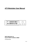
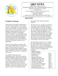
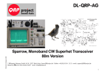
1
12kHz LIF Converter V2.43 – 9Mhz version
Please Note: This document supersedes all previously released documents and drawings on the
LIF subject. This is the latest and most up-to-date document at this time. While all previous
documents can be used as reference, for the most current technical information refer to this
document only.
Jan 17.2014.
Intro
The LIF2012 is the continued development of the LIF, which is now available as a kit. The LIF is
the down-converter hardware that works in conjunction with the MDSR software. The MDSR has
been developed as a stand-alone application and a spectrum analyzer has been programmed
that works in conjunction with the MDSR engine. The transceiver interface software OmniRig has
been implemented to control 48 different makes and models of radios. The MDSR software
package is available from our Yahoo user group for free for non-profit amateur radio purposes.
This provides a complete transceiver application package for PC desktop computers. The DADP
software has been discontinued – the MDSR software replaces the DADP. The up-converter
hardware is not yet available as a kit.
Due to the added functionality and the need to meet a wider audience, the concept of fitting the
LIF2012 PCB into the filter slot of the YAESU radio has been abandoned for now (in the future
when the LIF is available as a SMD board it might be possible to return to that concept). The
converter will now be external for the FT-817 and for the FT-897, which has additional space
available, internal (as per instructions by Guy Roels). The introduction of OmniRig has opened up
the amount of transceivers supported by the MDSR. Any receiver or transceiver with a 455kHz or
9MHz IF will work with the LIF2012 interface, the FT-817, FT-897, IC-703 and IC-706 have been
tested and confirmed.
Note: The LIF2012 kit will only allow for RX. With the “Lock to TXVR” function in the MDSR
software, the microphone or the DSP without modulation can be used to broadcast using the
transceivers’ internal modulator. Please check the MDSR manual for further details.
What is new for V2.4?
•
•
•
•
•
The LIF2012 converter is available as a kit (orders can be placed through the MDSR
website using a PayPal account) and features better mirror frequency suppression.
Both outputs of the SA612 are used
The MDSR software has been updated to allow for a wider range of LO frequencies.
The MDSR has been updated to set the radio to the most suitable mode for the available
LO resonator (“Lock to TXVR”).
To synchronize the MDSR and the transceiver, fine tuning is done via software.
1.
Technical Specifications
Hardware:
Local Oscillator Frequency
Input Frequency
Input Level (max)
Conversion Gain (max)
Output Level for S-9
LIF Bandwidth:
LIF Center Frequency:
Supply Voltage Range
2.
9MHz
9.015MHz (+/- 5kHz)
1mV – 20mVpp
55dB
0.7Vpp
+/- 5kHz
9 – 18kHz
9 – 15V
Creation of 12kHz LIF (Low Intermediate Frequency)
2.1 How to extract the IF from a radio
The LIF2012IC9M hardware takes the 9MHz IF, which is generated inside the radio before
the signal (while in RX) is filtered and demodulated, and converts it down to a 12kHz LIF
(Low Intermediate Frequency). All HF transceivers use one ceramic filter to separate the
USB spectrum from LSB spectrum and, at the same time, do this for RX as well as TX. This
creates one point in the transceivers where a 9MHz unidirectional IF is present. How this IF
is routed depends on the state of the transceiver.
Each transceiver is different. The models that have already been tested are posted on the
website http://users.skynet.be/myspace/mdsr/ . There is also a lot of information in the files
and photo section on the MDSRadio Yahoo user group.
The signal flow below shows how the LIF board is connected and how it affects the
performance of the radio. Everything after the filter section is disabled.
2.2 About the Local Oscillator Frequency
The LO frequency and the placement of the DSP filters is very important for the proper
functionality of the MDSR software. In order to make it easier to match the filters and the
BFO frequency with the available resonators, a wide BFO adjustment has been
implemented. This adjustment can now be individualized for each mode. In the “Lock to
TXVR” mode, the transceiver and the MDSR mode are synchronized to allow for the
optimization of the filter pass with the DSP filters of the MDSR.
2.3 Schematics of LIF converter
As a converter, the SA602 Gilbert cell is used. The ceramic crystal filter oscillator provides
the LO injection signal between 8.995MHz (depending on the filter available) and the output
is amplified and filtered with a TL072 by 20dB which provides an overall gain of about
35dB. A switchable 8kHz high pass filter linearizes the spectral response for the soundcard
and removes the low part of the frequencies coming out of the mixer. This improves the
dynamic performance for the demodulation. In the case of DRM or PSK31 signals, the filter
has to be bypassed. A 5V regulator stabilizes the voltage and therefore allows for a wider
supply voltage.
This converter works with any radio using a 9MHz IF system that provides a 1 – 20mV
signal for a S-9 meter reading at the optional filter port.
Note
There is some debate about the SA612 as being very sensitive to over modulation. This is
true when it is used as a 1st mixer in a radio design. For the LIF converter, it is the 3rd mixer,
the Gilbert cell’s performance and simplicity is ideal.
2.4 Building the Kit
In order to successfully assemble the kit, follow the instructions of this manual. As a
soldering iron, it is best to use a 24VAC temperature controlled unit, either with a magnetic
tip (heat rating 7) or electronically. The tip should be pencil sized.
The soldering eyes are quite fragile and very little force is required to peel them off the
board which will cause damage to the PCB. Use a pair of needle nosed pliers to bend the
leads of each component to match the holes on the PCB before inserting them.
The bill of material specifies the location of the specific parts and their values. Start by
inserting the resistors first and solder them in place before going on to L2. Next, insert the
Monolithic capacitors, solder them and then solder the tantalum capacitors, observing their
polarity. Place the trim potentiometer (P1) on the board, solder it. Next, solder the trimmer
capacitor (C14, nose pointing to C8) followed by the strip connector, L1 and the ceramic
filters. To shock proof the assembly, use a heat gun to glue the crystal filters on to the PCB.
Now all the passive components are on the board.
Note: C15, C17 and TB5 stay empty.
Functional testing procedure
This procedure ensures the safest way to confirm the function of the PCB and minimizes
the potential destruction of any of the parts.
•
•
•
•
Solder U3, the voltage regulator, onto the PCB. Make sure the front (flat side) faces
towards C21
Apply 12V to TB2, carefully observing the polarity. Now, measure the voltage at L2.
If it reads 8V the regulator is working correctly.
Solder U1 and U2 onto the PCB. Apply 12V to TB2 and measure with the
oscilloscope on U1 – pin6. There should be a sine wave present with amplitude of
approx. 2Vpp.
Insert the SIL jumper onto TB4 bridging pin 3 and 4 (counted from the top).
Connect the scope to TB3, noting the polarity. There has to be an AF (around
12kHz) noise floor. Turn P1 to the most sensitive setting and the noise floor will go
up. Apply a 1mV – 20mV 9MHz sine wave or the IF output of the receiver to the
input and now there should be a 12kHz signal representing the input signal in
phase and amplitude. Place the SIL jumper to bridge pin 4 and 5 and a signal with
a filter slope starting at 8kHz and dropping to 0 at about 2.5kHz will be present.
Note: If a scope is not available, this test can be performed by plugging the
LIF2012 into the soundcard. The MDSR and the MDSR-SA software have to be
installed on the computer. For instructions, please refer to the latest MDSR
software posted on the Yahoo MDSR group under the “files” section; the MDSR
software can also be downloaded there. (Membership is needed to access this file.
There is no cost to sign up.)
PCB Assembly Drawing
Note
Please refer to the assembly drawing above for additional information and the
polarization of the tantalum capacitors.
Bill of Material
BILL OF MATERIALS LIF2012.PCB
10/06/12
Value
Markings Qty. Location
9MHz
1
Xtal1
100n
104
1
C18
var
1
C14
470pF
471
1
C19
47pF
470
1
C13
100pF
101
2
C16
2n2
222
2
C6
C7
4n7
472
3
C9
C10 C11
10n
103
2
C3
C22
1nF
102
1
C2
220nF
224
3
C4
C5 C12
1uF
105
1
C8
4u7
475
1
C20
10uF
106
1
C21
1nF
102
1
Cf1
560uH
1
L2
10.7n
0
L1
1k
4
R1
R3
R7 R10
2k
1
P1
2k2
1
R8
10k
1
R9
22k
2
R4
R5
47k
2
R2
R6
78L08
1
U3
SA612
1
U1
TL072
1
U2
Description
Ceramic Resonator
Monolithic Capacitor
Variable Capacitor
Monolithic Capacitor
Monolithic Capacitor
Monolithic Capacitor
Monolithic Capacitor
Monolithic Capacitor
Monolithic Capacitor
Monolithic Capacitor
Monolithic Capacitor
Tantalum Capacitor
Tantalum Capacitor
Tantalum Capacitor
Monolithic Capacitor
Inductor
Var Inductor
Resistor 0.25W
Trimmer
Resistor 0.25W
Resistor 0.25W
Resistor 0.25W
Resistor 0.25W
Voltage Regulator
Gilbert Cell Mixer Osc.
Dual Op Amp, Low Noise
Note: TB5, C1, C17 and C15 stay empty and are not supplied
2.5 Adjusting the LIF2012
There are only two adjustments that the LIF unit requires: the conversion gain and the
flatness of the filter response.
For this adjustment procedure, the MDSR and the MDSR-SA software need to be installed
on the computer. Again, for instructions please refer to the current user manual posted on
the Yahoo MDSR group under the “files” section.
Setting the gain of the LIF converter
The 0dB point of the audio card is 0.7Vpp. Otherwise AM and SSB signals may be clipped.
To adjust the gain, connect an oscilloscope or an AF audio meter to the output of the
converter. Disable the RX RF amp of the radio. Set the demodulation to AM, which does
not use the option filter. Tune the receiver to a stable AM station and reduce the incoming
RF until the S-meter on the radio reads S9. Now set the transceiver to USB mode, utilizing
the option filter (the signal strength meter on the radio will be working but might not be
accurate). Adjust R1 until the maximum output does not exceed 0.2Vpp (150mV RMS).
Strong local AM signals above S9+6dB will be clipped by the audio card. When this
happens, the gain control of the radio has to be turned down to keep the S-meter below or
at S9. Short bursts of SSB signals above S9 will not cause noticeable distortion.
Setting Filter response flatness
Turn the variable coil L1 to archive the flattest response curve in the MDSR-SA. This will
not give a total flat curve and is dependent on the receiver’s characteristics.
Note: Do not use a ferric screw driver and be careful not to break the ferrite core of the coil.
3. Conclusion
This completes the assembly and the test of the LIF2012. We hope this unit will provide a
new enjoyable experience while listening to your radio through the LIF – MDSR computer
interface.
It is advisable to build the PCB into an aluminum box as shown in the Yahoo user group.
This is an “off the shelf” box made by Hammond. It is not necessary, but will provide better
isolation from TX radiation created by the radio.
Any issues and/or questions should be directed to the MDSRadio Yahoo group.
Thank you,
The MDSR and LIF development team.