1
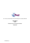
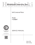
Unit 17 Denmore Industrial Estate, Denmore Road, Bridge of Don, Aberdeen AB23 8JW User Manual Fast Test Sub 117-2349-HH0 OPS-2345 Rev E User Manual Fast Test Sub 117-2349-HH0 Table of Contents Revision History .............................................................................................. ii Safety ............................................................................................................. iii 1 Introduction .............................................................................................. 1 1.1 General ............................................................................................ 1 1.2 Product Identification ........................................................................ 1 2 Technical Specification ............................................................................ 2 3 Technical Description .............................................................................. 3 3.1 The Fast Test Sub ............................................................................ 3 3.2 The Isolation Valve ........................................................................... 4 3.3 Collar Safe-Lok ................................................................................. 5 3.4 Test Port Saver Sub ......................................................................... 8 4 Operation ................................................................................................. 9 4.1 Setting up ......................................................................................... 9 4.2 Separating ........................................................................................ 9 4.3 Joining .............................................................................................. 9 4.4 Testing ............................................................................................. 9 4.5 Pre Job ........................................................................................... 10 4.6 During Job ...................................................................................... 10 4.7 Post Job ......................................................................................... 10 5 Maintenance .......................................................................................... 11 5.1 Introduction..................................................................................... 11 5.2 Schedule ........................................................................................ 11 5.3 Safety ............................................................................................. 11 5.4 Tools .............................................................................................. 12 5.5 Redress Procedure ......................................................................... 12 5.6 Maintenance Record Sheet ............................................................ 14 6 Testing .................................................................................................. 15 7 Parts List and Drawings ......................................................................... 16 8 Spares ................................................................................................... 18 Table 1 : Technical Data ................................................................................. 2 Table 2: Maintenance Record ....................................................................... 14 Table 3: Parts List ......................................................................................... 16 Table 4 : Redress Kit Part No RDK-2349-HH0.............................................. 18 Figure 1 : Fast Test Sub Safety ...................................................................... iii Figure 2 : Fast Test Sub ................................................................................. 2 Figure 3: The operation of the Fast Test Sub .................................................. 3 Figure 4: Isolation Valve ................................................................................. 4 Figure 5 : NPT Test Port and Saver Sub......................................................... 8 Figure 6 : Assembly Drawing ........................................................................ 17 OPS-2349 Rev E i User Manual Fast Test Sub 117-2349-HH0 Revision History Issue, Release Date Rev A, 19 Jun 08 Rev B, 18 May 11 Rev C, 05 Jul 11 Rev D, 30 Jan 12 Rev E, 31 Jan 12 OPS-2349 Rev E Description Initial Issue Parts List Updated for Alternative Isolation Valve (Item 5) Isolation valve Pt No 190-1871 Removed from Parts List Parts list updated Illustrations updated to reflect valve with single O-Ring ii User Manual Fast Test Sub 117-2349-HH0 Safety WARNING: Trapped air requires considerable time to compress and when it is compressed is highly dangerous. It has enough stored energy to separate parts with considerable force. All pressure equipment has a particular pressure rating and care must be taken to ensure that no item is used in a situation that may cause its working pressure to be exceeded. All personnel involved in pressure testing must be formally trained, competent and utilising the appropriate PPE. Safe Lok devices, where fitted, should be checked for positional security to avoid unnecessary movement of the collar Ensure the identification band/plate is fitted and is displaying the correct information as per the Tag Sheet/Index This equipment and the equipment it is attached to is heavy never position yourself below a suspended load Finger, Glove and loose clothing trap area Figure 1 : Fast Test Sub Safety OPS-2349 Rev E Care to be taken to avoid trapping fingers, gloves and loose clothing during stabbing procedure iii User Manual Fast Test Sub 117-2349-HH0 1 Introduction 1.1 General The Phuel Fast Test Sub is designed to save rig time while pressure testing the pressure control string when multiple wireline runs are required. The Fast Test Sub is inserted into the riser/lubricator at the position of the joint that is normally opened to insert or retrieve the tool string. After performing the first pressure test to check the integrity of the whole string, subsequent pressure tests can be made at the Fast Test Sub to verify the integrity of the only joint that was disconnected, rather than having to test the whole assembly. This is achieved by connecting a small hydraulic hand pump to pressure test between two seals from the outside. It is estimated that the use of the Fast Test Sub can reduce the time needed to pressure test by more than 30 minutes. The Fast Test Sub body is constructed in two parts that are connected by a collar. When the collar is backed off the two parts can be separated to break into the riser string. Both of the collars are Otis type with the Phuel safe-lok feature incorporated as standard. The test port is replaceable (saver sub) and can also be isolated from the well pressure by closing a metal seal valve. This user manual serves as an introduction to the equipment and contains the relevant specifications, operation, planning and maintenance instructions, parts list and drawings. 1.2 Product Identification Phuel products are identified by a unique serial number that facilitates full product traceability. Each product is supplied with a documentation pack that contains product certification and material/inspection reports. The serial number is always etched on the surface of the product but can sometimes be difficult to find or read after painting. A stainless steel band secures the nameplate tag that is stamped with the information shown. This tag should be located in the first instance to ensure that this manual P H U E L O IL T O O L S L T D refers to the correct equipment. A customer D E S C R IP T IO N & S IZ E identification number is also included to allow C U S T O M E R ID N o the customer to track the asset in their system. P H U E L ID N o 06 -X X X -X X M W P & S E R V IC E TEST D A TE OPS-2349 Rev E 1 User Manual Fast Test Sub 117-2349-HH0 2 Technical Specification Part No Connection Maximum Working Pressure Test Pressure Service Weight Overall Length (A) Make Up Length (B) Inner Diameter 117-2349-HH0 9 – 4 Otis Type Connection ½’’ NPT 10,000 Psi 15,000 Psi H2S 394 lbs/179 Kg 31.85’’/0.81M 29.17’’/0.74M 5.13’’/0.13M Table 1 : Technical Data Figure 2 : Fast Test Sub OPS-2349 Rev E 2 User Manual Fast Test Sub 117-2349-HH0 3 Technical Description 3.1 The Fast Test Sub The Fast Test Sub provides a single connection in the riser string that can be broken and then made up and tested without the need to pressure test the whole string, thus reducing the operational time required to install tools in the well. The figure below shows the operational sequence for the fast test sub. Notice that the seals are not exposed when the sub is separated, which helps avoid damage when stabbing back in. Isolation Valve Seal Break Here Test Port Figure 3: The operation of the Fast Test Sub OPS-2349 Rev E 3 User Manual Fast Test Sub 117-2349-HH0 3.2 The Isolation Valve The isolation valve is located at the test port and consists of a metal-to-metal cone seal that is energised by tightening the valve with a suitable hexagonal key. The valve should be open (i.e screw backed out) when testing between the o-rings and closed (screwed in) when wishing to isolate from the well pressure. The circlip prevents the full removal of the valve. Closed for Isolation Open for Testing Figure 4: Isolation Valve OPS-2349 Rev E 4 User Manual Fast Test Sub 117-2349-HH0 3.3 Collar Safe-Lok The safe collar lock is designed to provide safe handling of the union collars. In addition it can be used to prevent accidental back off of the collar. The following shows the sequence for correct operation. 3.3.1 Preparing the Safe-Lok Collar After removing the thread protector the collar will be set in the lower position and must be moved to the high position before making up the connection. With both hands raise the collar ensuring the Stop Pins go through the gaps in the raised rim Rotate the collar through 90° and gently lower onto the raised rim. Ensure collar rests into the grooved area OPS-2349 Rev E 5 User Manual Fast Test Sub 117-2349-HH0 3.3.2 Making up the Safe-Lok Collar Lift and stab the pin into the mating box and check that there are no signs of damage to the o-ring (caused by being misaligned while stabbing in). With both hands raise the collar clear of the grooved area on the raised rim and rotate through 90°. Lower the collar until it reaches the top of the threads. Turn the collar anticlockwise until the start of the thread is found and then start turning clockwise to make up the collar to the box thread. When almost made up fully release the plungers from the locked open position. Tighten the collar down. OPS-2349 Rev E 6 User Manual Fast Test Sub 117-2349-HH0 3.3.3 Breaking the Safe-Lok Collar Unscrew the collar completely Lift the collar up, ensure the stop pins go through the gaps in the raised rim. Rotate the collar 90° and lower gently so that the pins rest in the grooved portion of the raised rim. The connection can now be separated without any risk of dropping the collar. OPS-2349 Rev E 7 User Manual Fast Test Sub 117-2349-HH0 3.4 Test Port Saver Sub The saver sub provides the ability to change a damaged pressure fitting without repairing or replacing a major component. The saver sub is held in place by two socket head cap screws and is sealed by means of an o-ring. With the Fast Test Sub the saver block may be covered by the protector, which is designed to prevent damage to the connected fitted when the tool is lying on the deck. S aver S ub P rotector B lock Figure 5 : NPT Test Port and Saver Sub OPS-2349 Rev E 8 User Manual Fast Test Sub 117-2349-HH0 4 Operation All operations to be carried out by suitably qualified and competent personnel 4.1 Setting up 1. Locate the Fast Test Sub at the point in the riser where the connection will be broken to facilitate the insertion or removal of the tool string (normally immediately above the wireline valve). 2. Attach the male part of the quick release fitting to the Fast Test Sub with the mating part on the test hose assembly. Attach the test hose at this time. 3. Open the isolation valve. 4.2 Separating 1. 2. 3. 4. Secure a lifting clamp to the top of the riser. Close the isolation valve and ensure the test hose is detached Back off the safe-lok collar and lock in the high position. Lift the riser upwards 6-8 inches so that the two parts are clear of each other. 5. Lower the riser complete with the top half of the Fast Test Sub and change the tool string 4.3 Joining 1. Check the inside of the Fast Test Sub to ensure that the o-rings are in place and are in good condition – change if necessary. 2. Before lifting the riser ensure that the collar for the fast test sub is still set in the high position. 3. Position the top half of the Fast Test sub with the riser over the connection and slowly stab in ensuring that the string is as vertical as possible. Ensure that the sub is fully engaged. 4. Lower the collar and make up. 5. Attach the test hose 4.4 Testing 1. Close the isolation valve by tightening the valve as far as possible 2. Apply 3000 psi pressure then open isolation valve and confirm there is a significant drop in pressure 3. Apply pressure to the test line – bleed of a few times to minimise the amount of trapped air. 4. Apply the test pressure of 1.2 x maximum expected well pressure (or 10,000 psi) and hold for 10 minutes. No leaks acceptable. If leaks occur then the joint will need to separated again the o-rings changed OPS-2349 Rev E 9 User Manual Fast Test Sub 117-2349-HH0 5. Bleed off the pressure 6. Close the isolation valve and detach the test hose 4.5 Pre Job Ensure thread protectors are fitted Check maintenance record sheet and ensure the equipment has been maintained by competent personnel Check all certification is in date Confirm information band is fitted and correct Ensure equipment is suitable for the maximum working pressures and services involved Ensure ‘O’ ring is seated correctly and there are no signs of damage Ensure threads are clean Inspect for signs of damage Pressure test to 1.2x the maximum well pressure Carry out a collar lock test and ensure correct operation Ensure all connections are tight and that the test port is tightly fitted Ensure that spare o-rings are available and sent with the equipment. Ensure isolation valve is moving freely 4.6 During Job Ensure collar lock has operated correctly and the collar is locked in position Avoid excessive movement of the riser string 4.7 Post Job Inspect for signs of damage and report any findings Ensure threads are cleaned and the re-greased Ensure thread protectors are fitted OPS-2349 Rev E 10 User Manual Fast Test Sub 117-2349-HH0 5 Maintenance All maintenance to be carried out by suitably qualified and competent personnel 5.1 Introduction Regular maintenance of the equipment using Phuel redress kits or Phuel approved parts is essential to its continued safe operation. Ensure that the pre and post job operating procedures are followed and that maintenance records are kept. 5.2 Schedule The maintenance schedule may be governed by international or company standards and the following is considered to be the minimum requirements. 5.2.1 Pre & Post Job Refer to Section 4.5 and Section 4.7 for details 5.2.2 Yearly Disassemble fast test sub (5.5.1) clean and degrease all components Inspect the condition of all sealing surfaces and surface coatings Re-coat threads and sealing surfaces if necessary. If in doubt contact Phuel Oil Tools Ltd Replace all elastomeric seals with items from redress kit (Table 4) Re-grease components Re-assemble (5.5.2) Pressure test to maximum working pressure Inspect paint work and repair as necessary 5.2.3 Five Yearly Yearly Maintenance (plus the following) Carry out 100% surface NDE on all surfaces Pressure test to test pressure witnessed by certifying authority 5.3 Safety Many of the components are heavy and should not be lifted without lifting aids Wear appropriate personal protective equipment Do not over exert yourself while using torque wrenches. Use appropriate mechanical advantages when available. OPS-2349 Rev E 11 User Manual Fast Test Sub 117-2349-HH0 Ensure that all tools and equipment are in good condition and are suitable for the intended use. 5.4 Tools The following tools are required: 2 x Memac Chain Wrench (No3 with 14’’ chain) Other pipe wrenches may be used but will mark equipment 3/8 hex Allen key 5/16 hex Allen key ½’’ Spanner 7/8’’ Spanner (If NPT plug to be fitted) Circlip pliers Wire brush 5.5 Redress Procedure 5.5.1 Dis-Assembly Operate collar safe-lok system to release the collar. Loosen the collar and lock in the up position Remove the top sub from the bottom sub Remove 4 Stop Pins and washers from the split collar on the top sub Loosen split rings from collar and remove from split collar. Remove split collar from the top sub Remove 4 Stop Pins and washers from the split collar on the bottom sub Loosen split rings from collar and remove from split collar. Remove split collar from the bottom sub Remove the saver block and test port from the bottom sub Remove the circlip holding the equalisation valve in and remove the equalisation valve Remove and discard all ‘O’ rings Degrease and clean all components Inspect for signs of damage Fit thread protectors 5.5.2 Re-Assembly Remove thread protectors Inspect all threads for damage and clean with wire brush Fit internal and external ‘O’ rings to the bottom sub Fit ‘O’ rings to the equalisation valve and test port Grease equalisation valve ‘O’ rings and thread Fit equalisation valve to bottom sub tighten down and fit circlip OPS-2349 Rev E 12 User Manual Fast Test Sub 117-2349-HH0 Grease test port ‘O’ ring and fit to bottom sub using 2 screws (0.75’’/1.9cm length) and washers Fit saver block over test port on bottom sub using 2 screws (1.25’’/3cm length) and washers Slide the Split Collar over the bottom sub, make up the two halves of the split ring and tighten down until the ends are flush with the collar. Back off slightly to align the holes Insert 4 Stop Pins and washers Slide the Split Collar over the top sub, make up the two halves of the split ring and tighten down until the ends are flush with the collar. Back off slightly to align the holes Insert 4 Stop Pins and washers Operate Collar Safe-Lok system and hold collar in the up position Grease OD of top sub and internal ‘O’ rings of the bottom sub Make up the top sub to the bottom sub release the collar and tighten check operation of the collar safe-lok system to ensure the collar is locked in position OPS-2349 Rev E 13 User Manual Fast Test Sub 117-2349-HH0 5.6 Maintenance Record Sheet Date Type of Performed Performed Maintenance By Verified By Comments Table 2: Maintenance Record OPS-2349 Rev E 14 User Manual Fast Test Sub 117-2349-HH0 6 Testing All testing is to be carried out in the designated test area and by suitably qualified and competent personnel. WARNING: Trapped air requires considerable time to compress and when it is compressed is highly dangerous. It has enough stored energy to separate parts with considerable force. On completion of reassembly fit the appropriate test caps to either end of the Fast Test sub and NPT plug to test port Ensure equalisation valve is closed Fill with test fluid and bleed off any air in the system Apply a pressure of 500 psi and ensure pressure holds for a minimum of 10 minutes Increase pressure to 10,000 psi (Maximum Working Pressure), allow to stabilise and maintain this pressure until it is evident there are no apparent leaks. Bleed off pressure, drain test fluid and dry Remove test caps and plug Apply coating of de-watering solution to protect the bore and threads Fit thread protectors On completion of all maintenance ensure the maintenance record sheet (5.6) is completed OPS-2349 Rev E 15 User Manual Fast Test Sub 117-2349-HH0 7 Parts List and Drawings Item Number 1 2 3 4 5 6 7 8 9 10 11 12 13 14 15 100 101 Part Number 117-2291-480 117-2290-480 110-2053-480 110-2054-480 190-1718-316 900-1631-480 110-2329-3A4 SHC-0583-3A4 WNL-0580-STL 117-2166-STL SHC-0592-STL 801-0119-V90 801-0438-V90 801-0108-V90 117-2150-N66 910-2155-N66 910-2156-N66 Quantity 1 1 2 2 1 1 8 2 12 1 2 1 3 1 1 1 1 Description TOP SUB BOTTOM SUB COLLAR 9-4 (SPLIT TYPE) SPLIT RING (9-4) Equalization Valve TEST PORT STOP PIN Soc Hd Cap Size 1/2 Length 0.75 in Nord Lock Washer (M12) CIRCLIP INTERNAL 19mm (DHO-19) Soc Hd Cap Size 1/2 Length 2.5 in O-Ring - B.S Size 119 O-Ring - B.S Size 438 O-Ring - B.S Size 108 SAVER-BLOCK 9-4 ACME MALE PROTECTOR 9-4 ACME FEMALE PROTECTOR Table 3: Parts List Note 1: Thread protectors (items 100 and 101) not shown on Assembly Drawing (Figure 6) OPS-2349 Rev E 16 User Manual Fast Test Sub 117-2349-HH0 Figure 6 : Assembly Drawing OPS-2349 Rev E 17 User Manual Fast Test Sub 117-2349-HH0 8 Spares Use only spares supplied or approved by Phuel Oil Tools Ltd. It is recommended that sufficient quantities of the following spares be maintained to ensure that the equipment is always available when required. Elastomeric spares are supplied in Viton material as standard. Many other materials are available please specify when ordering. Part No Qty 801-0119-V90 801-0438-V90 801-0108-V90 1 3 1 Description Comments O-Ring - B.S Size 119 O-Ring - B.S Size 438 O-Ring - B.S Size 108 Table 4 : Redress Kit Part No RDK-2349-HH0 8.1.1 Individual Items Individual items may be ordered as required using the part number specified Note: O-Rings conform to industry standards and may be substituted with those from other suppliers -– at the sole risk of the user. OPS-2349 Rev E 18