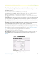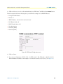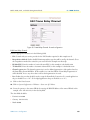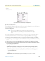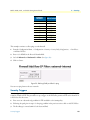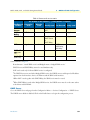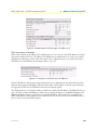
1
Models 2603, 2621, and 2635
IPLink Series High Speed Routers
Getting Started Guide
Document Number: 03328U1-001 Rev. A
Part Number: 07M2600Ser-GS
Revised: March 24, 2006
Patton Electronics Company, Inc.
7622 Rickenbacker Drive
Gaithersburg, MD 20879 USA
Tel: +1 (301) 975-1000
Fax: +1 (301) 869-9293
Support: +1 (301) 975-1007
Web: www.patton.com
E-mail: [email protected]
Copyright © 2003–2006, Patton Electronics Company. All rights reserved.
The information in this document is subject to change without notice. Patton Electronics assumes no liability for errors that may appear in this document.
Warranty Information
The software described in this document is furnished under a license and may be used
or copied only in accordance with the terms of such license.
Patton Electronics warrants all IPLink Series router components to be free from
defects, and will—at our option—repair or replace the product should it fail within
one year from the first date of the shipment.
This warranty is limited to defects in workmanship or materials, and does not cover
customer damage, abuse or unauthorized modification. If the product fails to perform
as warranted, your sole recourse shall be repair or replacement as described above.
Under no condition shall Patton Electronics be liable for any damages incurred by the
use of this product. These damages include, but are not limited to, the following: lost
profits, lost savings and incidental or consequential damages arising from the use of or
inability to use this product. Patton Electronics specifically disclaims all other warranties, expressed or implied, and the installation or use of this product shall be deemed
an acceptance of these terms by the user.
Note
Conformity documents of all Patton products can be viewed online at
www.patton.com under the appropriate product page.
Summary Table of Contents
1 General Information...................................................................................................................................... 17
2 Product Overview.......................................................................................................................................... 24
3 Initial Configuration ..................................................................................................................................... 27
4 Ethernet LAN Port ........................................................................................................................................ 40
5 Serial Port Configuration .............................................................................................................................. 44
6 WAN Services ................................................................................................................................................ 50
7 Security ......................................................................................................................................................... 68
8 DHCP and DNS Configuration.................................................................................................................... 82
9 IP Services ..................................................................................................................................................... 93
10 System Configuration.................................................................................................................................... 96
11 SNTP Client Configuration ........................................................................................................................ 104
12 System Status............................................................................................................................................... 108
13 Contacting Patton for assistance ................................................................................................................. 112
A Compliance information ............................................................................................................................ 115
B Specifications .............................................................................................................................................. 118
C Cable Recommendations ............................................................................................................................ 122
D IPLink Physical Connectors ....................................................................................................................... 124
E Command Line Interface (CLI) Operation ................................................................................................ 129
3
Contents
Summary Table of Contents ......................................................................................................................... 3
Contents ......................................................................................................................................................... 4
List of Figures ............................................................................................................................................... 10
List of Tables ................................................................................................................................................ 12
About this guide ........................................................................................................................................... 13
Audience............................................................................................................................................................... 13
Structure............................................................................................................................................................... 13
Precautions ........................................................................................................................................................... 14
Safety when working with electricity ...............................................................................................................14
General observations .......................................................................................................................................15
Factory default parameters .................................................................................................................................... 15
Typographical conventions used in this document................................................................................................ 16
General conventions .......................................................................................................................................16
1 General Information...................................................................................................................................... 17
IPLink Series High Speed Routers overview ..........................................................................................................18
General attributes ............................................................................................................................................18
Ethernet ..........................................................................................................................................................19
Protocol support .............................................................................................................................................19
PPP Support ...................................................................................................................................................19
WAN Interfaces ..............................................................................................................................................19
Management ...................................................................................................................................................19
Security ...........................................................................................................................................................20
Front Panel Status LEDs and Console Port .....................................................................................................20
Console port .............................................................................................................................................21
Rear panel connectors and switches .................................................................................................................21
Power connector .......................................................................................................................................22
AC universal power supply ..................................................................................................................22
48 VDC power supply ........................................................................................................................22
Ethernet port (outlined in green) ...............................................................................................................22
MDI-X ......................................................................................................................................................22
2 Product Overview.......................................................................................................................................... 24
Introduction ..........................................................................................................................................................25
Applications Overview...........................................................................................................................................26
3 Initial Configuration ..................................................................................................................................... 27
Hardware installation ............................................................................................................................................28
What you will need .........................................................................................................................................28
Interface cable installation ...............................................................................................................................28
Installing an interface cable on the IPLink 2603’s T1/E1 interface port ....................................................29
Installing an interface cable on the IPLink 2621’s X.21 interface port .......................................................31
4
Contents
Models 2603, 2621, and 2635 Getting Started Guide
Installing an interface cable on the IPLink 2635’s V.35 interface port .......................................................33
Installing the AC power cord ..........................................................................................................................34
Installing the Ethernet cable ............................................................................................................................36
IP address modification ...................................................................................................................................37
Web Operation and Configuration .................................................................................................................37
PC Configuration .....................................................................................................................................37
Web Browser .............................................................................................................................................37
4 Ethernet LAN Port ........................................................................................................................................ 40
Introduction ..........................................................................................................................................................41
LAN Connections ...........................................................................................................................................41
Ethernet Port ..................................................................................................................................................41
5 Serial Port Configuration .............................................................................................................................. 44
WAN Serial Port Configuration ............................................................................................................................45
Serial Interface ................................................................................................................................................45
Variables ...................................................................................................................................................45
Web Interface Configuration ....................................................................................................................46
T1/E1 Interface Configuration .......................................................................................................................46
Configuring the IPLink Series 2603 for T1 Operation ..............................................................................47
Web Configuration .............................................................................................................................47
Configuring the IPLink Series 2603 for E1 Operation ..............................................................................48
Web Configuration .............................................................................................................................48
6 WAN Services ................................................................................................................................................ 50
WAN Services .......................................................................................................................................................51
Configuring the IPLink Series 2603 for E1 Operation ..............................................................................51
Web Configuration .............................................................................................................................51
WAN Service Configuration..................................................................................................................................52
PPP Configuration ..........................................................................................................................................52
PPP Bridged ..............................................................................................................................................52
PPP Bridged Remote Site Configuration ............................................................................................52
Central Site Configuration ..................................................................................................................53
PPP Routed ...............................................................................................................................................54
Remote site configuration ...................................................................................................................54
Central Site Configuration ..................................................................................................................57
LMI Management (Frame Relay links) ...........................................................................................................58
LMI Configuration ...................................................................................................................................58
Frame Relay Local Management Interface ..........................................................................................58
LMI Configuration Options ...............................................................................................................59
Web Configuration Methods ....................................................................................................................59
Frame Relay Configuration .............................................................................................................................60
Frame Relay bridged .................................................................................................................................61
Remote Site Configuration .................................................................................................................61
Central site configuration ...................................................................................................................62
Frame Relay Routed ..................................................................................................................................63
5
Models 2603, 2621, and 2635 Getting Started Guide
Contents
Remote Site Configuration .................................................................................................................63
Central site configuration ...................................................................................................................66
7 Security ......................................................................................................................................................... 68
Introduction ..........................................................................................................................................................69
Configuring the router ..........................................................................................................................................69
Configuring the security interfaces.........................................................................................................................71
Configuring Security Policies ..........................................................................................................................73
Deleting a security Policy ..........................................................................................................................74
Enabling the Firewall.............................................................................................................................................74
Firewall Portfilters .................................................................................................................................................74
Security Triggers....................................................................................................................................................75
Intrusion Detection System (IDS) .........................................................................................................................78
Introduction to NAT.............................................................................................................................................80
Enabling NAT ................................................................................................................................................80
Global address pool and reserved map .............................................................................................................80
8 DHCP and DNS Configuration.................................................................................................................... 82
Introduction ..........................................................................................................................................................83
Services and features normally associated with each other ................................................................................83
DHCP Server .................................................................................................................................................84
Parameters for the DHCP Server subnet ...................................................................................................86
IP Addresses to be available on this subnet ................................................................................................87
DNS server option information .................................................................................................................88
Default gateway option information ..........................................................................................................89
Additional option information ..................................................................................................................89
DHCP Relay ..................................................................................................................................................89
Configuration of the DHCP Relay ............................................................................................................89
DNS Relay ......................................................................................................................................................91
Configuring the DNS Relay ......................................................................................................................91
9 IP Services ..................................................................................................................................................... 93
IP Services .............................................................................................................................................................94
WEB Server ....................................................................................................................................................94
CLI Configuration ....................................................................................................................................94
Associated Ports for the different System (IP) Services .....................................................................................95
10 System Configuration.................................................................................................................................... 96
Introduction ..........................................................................................................................................................97
Authentication.......................................................................................................................................................97
Alarm ....................................................................................................................................................................98
Remote Access .......................................................................................................................................................99
Update ................................................................................................................................................................100
Save .....................................................................................................................................................................100
Backup/Restore ...................................................................................................................................................100
Restart .................................................................................................................................................................101
6
Contents
Models 2603, 2621, and 2635 Getting Started Guide
Website Settings ..................................................................................................................................................101
Error Log.............................................................................................................................................................102
SNMP Daemon ..................................................................................................................................................102
System Tools .......................................................................................................................................................103
11 SNTP Client Configuration ........................................................................................................................ 104
Introduction ........................................................................................................................................................105
Configuring the SNTP Client .............................................................................................................................105
SNTP Client Mode Configuration Parameters .............................................................................................105
SNTP Client General Configuration Parameters ..........................................................................................106
System Clock Setting...........................................................................................................................................106
12 System Status............................................................................................................................................... 108
System Status.......................................................................................................................................................109
Port Connection Status .................................................................................................................................109
LAN Status ...................................................................................................................................................110
WAN Status .................................................................................................................................................110
Hardware Status ............................................................................................................................................110
Defined Interfaces .........................................................................................................................................110
Status LEDs.........................................................................................................................................................111
13 Contacting Patton for assistance ................................................................................................................. 112
Introduction ........................................................................................................................................................113
Contact information............................................................................................................................................113
Patton support headquarters in the USA .......................................................................................................113
Alternate Patton support for Europe, Middle East, and Africa (EMEA) ........................................................113
Warranty Service and Returned Merchandise Authorizations (RMAs).................................................................113
Warranty coverage ........................................................................................................................................113
Out-of-warranty service ...........................................................................................................................114
Returns for credit ....................................................................................................................................114
Return for credit policy ...........................................................................................................................114
RMA numbers ..............................................................................................................................................114
Shipping instructions ..............................................................................................................................114
A Compliance information ............................................................................................................................ 115
Compliance .........................................................................................................................................................116
EMC .............................................................................................................................................................116
Safety ............................................................................................................................................................116
PSTN Regulatory (2603 Model only) ...........................................................................................................116
Radio and TV Interference (FCC Part 15) ..........................................................................................................116
CE Declaration of Conformity ............................................................................................................................116
FCC Part 68 (ACTA) Statement (Model 2603 only)...........................................................................................116
Industry Canada Notice (2603 Model only) ........................................................................................................117
B Specifications .............................................................................................................................................. 118
General Characteristics ........................................................................................................................................119
Ethernet ..............................................................................................................................................................119
7
Models 2603, 2621, and 2635 Getting Started Guide
Contents
Sync Serial Interface ............................................................................................................................................119
T1/E1 Interface ...................................................................................................................................................119
Protocol Support .................................................................................................................................................120
PPP Support........................................................................................................................................................120
Management .......................................................................................................................................................120
Security ...............................................................................................................................................................121
Dimensions .........................................................................................................................................................121
Power and Power Supply Specifications...............................................................................................................121
AC universal power supply ......................................................................................................................121
48 VDC power supply ............................................................................................................................121
C Cable Recommendations ............................................................................................................................ 122
Ethernet Cable ....................................................................................................................................................123
Adapter................................................................................................................................................................123
D IPLink Physical Connectors ....................................................................................................................... 124
RJ-45 shielded 10/100 Ethernet port...................................................................................................................125
RJ-45 non-shielded RS-232 console port (EIA-561)............................................................................................125
Serial port............................................................................................................................................................126
V.35 (M/34 and DB-25 Connector) .............................................................................................................126
X.21 (DB-15 Connector) ..............................................................................................................................127
E1/T1 (RJ-48C Connector) ..........................................................................................................................128
E Command Line Interface (CLI) Operation ................................................................................................ 129
Introduction ........................................................................................................................................................130
CLI Terminology ................................................................................................................................................130
Local (VT-100 emulation) ............................................................................................................................130
Remote (Telnet) ............................................................................................................................................130
Using the Console .........................................................................................................................................130
Administering user accounts ................................................................................................................................132
Adding new users ..........................................................................................................................................132
Setting user passwords ...................................................................................................................................132
Changing user settings ..................................................................................................................................133
Controlling login access ...........................................................................................................................133
Controlling user access ............................................................................................................................133
8
Contents
9
Models 2603, 2621, and 2635 Getting Started Guide
List of Figures
1
2
3
4
5
6
7
8
9
10
11
12
13
14
15
16
17
18
19
20
21
22
23
24
25
26
27
28
29
30
31
32
33
34
35
36
37
38
39
40
41
42
43
44
45
46
47
IPLink Series Router (Model 2635 shown) . . . . . . . . . . . . . . . . . . . . . . . . . . . . . . . . . . . . . . . . . . . . . . . . . . . . 20
Sync Serial Application . . . . . . . . . . . . . . . . . . . . . . . . . . . . . . . . . . . . . . . . . . . . . . . . . . . . . . . . . . . . . . . . . . . 26
T1/E1 Application . . . . . . . . . . . . . . . . . . . . . . . . . . . . . . . . . . . . . . . . . . . . . . . . . . . . . . . . . . . . . . . . . . . . . . 26
Rear View of the 2603/T showing location of Ethernet and WAN connectors . . . . . . . . . . . . . . . . . . . . . . . . . 29
RJ-48C pinout diagram . . . . . . . . . . . . . . . . . . . . . . . . . . . . . . . . . . . . . . . . . . . . . . . . . . . . . . . . . . . . . . . . . . 29
Rear view of the 2603/K showing location of Ethernet and WAN connectors . . . . . . . . . . . . . . . . . . . . . . . . . 30
Rear view of the 2621 showing location of Ethernet and X.21 connectors . . . . . . . . . . . . . . . . . . . . . . . . . . . . 31
Case being opened with a screwdriver . . . . . . . . . . . . . . . . . . . . . . . . . . . . . . . . . . . . . . . . . . . . . . . . . . . . . . . . 32
Location of DTE/DCE board . . . . . . . . . . . . . . . . . . . . . . . . . . . . . . . . . . . . . . . . . . . . . . . . . . . . . . . . . . . . . . 32
Rear view of the 2635 showing location of Ethernet and V.35 connectors . . . . . . . . . . . . . . . . . . . . . . . . . . . . 33
Connecting the 2635 to a DCE device . . . . . . . . . . . . . . . . . . . . . . . . . . . . . . . . . . . . . . . . . . . . . . . . . . . . . . . 34
Power connector location on rear panel (Model 2603/T shown) . . . . . . . . . . . . . . . . . . . . . . . . . . . . . . . . . . . . 35
IPLink front panel LEDs and Console port locations (Model 2603 shown) . . . . . . . . . . . . . . . . . . . . . . . . . . . 36
Model 2603 home page . . . . . . . . . . . . . . . . . . . . . . . . . . . . . . . . . . . . . . . . . . . . . . . . . . . . . . . . . . . . . . . . . . 38
Model 2621 home page . . . . . . . . . . . . . . . . . . . . . . . . . . . . . . . . . . . . . . . . . . . . . . . . . . . . . . . . . . . . . . . . . . 38
Model 2635 home page . . . . . . . . . . . . . . . . . . . . . . . . . . . . . . . . . . . . . . . . . . . . . . . . . . . . . . . . . . . . . . . . . . 39
Ethernet LAN port IP address configuration . . . . . . . . . . . . . . . . . . . . . . . . . . . . . . . . . . . . . . . . . . . . . . . . . . . 41
Basic Ethernet port attributes . . . . . . . . . . . . . . . . . . . . . . . . . . . . . . . . . . . . . . . . . . . . . . . . . . . . . . . . . . . . . . 42
Advanced Ethernet port attributes . . . . . . . . . . . . . . . . . . . . . . . . . . . . . . . . . . . . . . . . . . . . . . . . . . . . . . . . . . 42
Configurable Ethernet parameters . . . . . . . . . . . . . . . . . . . . . . . . . . . . . . . . . . . . . . . . . . . . . . . . . . . . . . . . . . . 43
Model 2621 X.21 serial port configuration parameters . . . . . . . . . . . . . . . . . . . . . . . . . . . . . . . . . . . . . . . . . . . 46
Model 2635 V.35 serial port configuration parameters . . . . . . . . . . . . . . . . . . . . . . . . . . . . . . . . . . . . . . . . . . . 46
Model 2603 T1/E1 WAN port configuration parameters . . . . . . . . . . . . . . . . . . . . . . . . . . . . . . . . . . . . . . . . . 47
T1 configuration . . . . . . . . . . . . . . . . . . . . . . . . . . . . . . . . . . . . . . . . . . . . . . . . . . . . . . . . . . . . . . . . . . . . . . . . 47
E1 port configuration . . . . . . . . . . . . . . . . . . . . . . . . . . . . . . . . . . . . . . . . . . . . . . . . . . . . . . . . . . . . . . . . . . . . 48
E1 port configuration . . . . . . . . . . . . . . . . . . . . . . . . . . . . . . . . . . . . . . . . . . . . . . . . . . . . . . . . . . . . . . . . . . . . 51
PPP Bridged Application . . . . . . . . . . . . . . . . . . . . . . . . . . . . . . . . . . . . . . . . . . . . . . . . . . . . . . . . . . . . . . . . . 52
WAN services’ options . . . . . . . . . . . . . . . . . . . . . . . . . . . . . . . . . . . . . . . . . . . . . . . . . . . . . . . . . . . . . . . . . . . 53
PPP Routed Application . . . . . . . . . . . . . . . . . . . . . . . . . . . . . . . . . . . . . . . . . . . . . . . . . . . . . . . . . . . . . . . . . . 54
PPP Routed Configuration menu . . . . . . . . . . . . . . . . . . . . . . . . . . . . . . . . . . . . . . . . . . . . . . . . . . . . . . . . . . . 55
Edit IP address of WAN port . . . . . . . . . . . . . . . . . . . . . . . . . . . . . . . . . . . . . . . . . . . . . . . . . . . . . . . . . . . . . . 56
Configuring the gateway . . . . . . . . . . . . . . . . . . . . . . . . . . . . . . . . . . . . . . . . . . . . . . . . . . . . . . . . . . . . . . . . . . 56
PPP link status . . . . . . . . . . . . . . . . . . . . . . . . . . . . . . . . . . . . . . . . . . . . . . . . . . . . . . . . . . . . . . . . . . . . . . . . . 57
LMI Configuration webpage . . . . . . . . . . . . . . . . . . . . . . . . . . . . . . . . . . . . . . . . . . . . . . . . . . . . . . . . . . . . . . . 60
Frame Relay bridged creation . . . . . . . . . . . . . . . . . . . . . . . . . . . . . . . . . . . . . . . . . . . . . . . . . . . . . . . . . . . . . . 61
Frame Relay Channel configuration . . . . . . . . . . . . . . . . . . . . . . . . . . . . . . . . . . . . . . . . . . . . . . . . . . . . . . . . . 62
Frame Relay routed application . . . . . . . . . . . . . . . . . . . . . . . . . . . . . . . . . . . . . . . . . . . . . . . . . . . . . . . . . . . . 63
Frame Relay routed configuration . . . . . . . . . . . . . . . . . . . . . . . . . . . . . . . . . . . . . . . . . . . . . . . . . . . . . . . . . . . 64
Frame Relay Channel - Routed configuration . . . . . . . . . . . . . . . . . . . . . . . . . . . . . . . . . . . . . . . . . . . . . . . . . . 65
IP route for Frame Relay routed application . . . . . . . . . . . . . . . . . . . . . . . . . . . . . . . . . . . . . . . . . . . . . . . . . . . 66
PPP routed WAN service for Security Firewall example . . . . . . . . . . . . . . . . . . . . . . . . . . . . . . . . . . . . . . . . . . 70
IP address of PPP routed WAN service . . . . . . . . . . . . . . . . . . . . . . . . . . . . . . . . . . . . . . . . . . . . . . . . . . . . . . . 70
Valid gateway route . . . . . . . . . . . . . . . . . . . . . . . . . . . . . . . . . . . . . . . . . . . . . . . . . . . . . . . . . . . . . . . . . . . . . 71
Security configuration home page . . . . . . . . . . . . . . . . . . . . . . . . . . . . . . . . . . . . . . . . . . . . . . . . . . . . . . . . . . . 72
Define ‘ip1’ interface as Internal . . . . . . . . . . . . . . . . . . . . . . . . . . . . . . . . . . . . . . . . . . . . . . . . . . . . . . . . . . . . 72
Define ‘ppp-0’ interface as External . . . . . . . . . . . . . . . . . . . . . . . . . . . . . . . . . . . . . . . . . . . . . . . . . . . . . . . . . 73
Security Policy Configuration hyperlink . . . . . . . . . . . . . . . . . . . . . . . . . . . . . . . . . . . . . . . . . . . . . . . . . . . . . . 73
10
Models 2603, 2621, and 2635 Getting Started Guide
48
49
50
51
52
53
54
55
56
57
58
59
60
61
62
63
64
65
66
67
68
69
70
71
72
73
74
75
76
77
78
79
80
81
82
83
84
85
86
New Policy link to configuration webpage . . . . . . . . . . . . . . . . . . . . . . . . . . . . . . . . . . . . . . . . . . . . . . . . . . . . 73
Deleting a Security Policy . . . . . . . . . . . . . . . . . . . . . . . . . . . . . . . . . . . . . . . . . . . . . . . . . . . . . . . . . . . . . . . . . 74
Defining ICMP port filter for ping . . . . . . . . . . . . . . . . . . . . . . . . . . . . . . . . . . . . . . . . . . . . . . . . . . . . . . . . . . 75
Configuring TCP port filter for FTP . . . . . . . . . . . . . . . . . . . . . . . . . . . . . . . . . . . . . . . . . . . . . . . . . . . . . . . . 76
Adding trigger for FTP data transfer . . . . . . . . . . . . . . . . . . . . . . . . . . . . . . . . . . . . . . . . . . . . . . . . . . . . . . . . . 77
NAT Global Address Pool configuration . . . . . . . . . . . . . . . . . . . . . . . . . . . . . . . . . . . . . . . . . . . . . . . . . . . . . 81
NAT Reserved mapping configuration . . . . . . . . . . . . . . . . . . . . . . . . . . . . . . . . . . . . . . . . . . . . . . . . . . . . . . . 81
DHCP Server web page . . . . . . . . . . . . . . . . . . . . . . . . . . . . . . . . . . . . . . . . . . . . . . . . . . . . . . . . . . . . . . . . . . 85
DHCP server configuration web page . . . . . . . . . . . . . . . . . . . . . . . . . . . . . . . . . . . . . . . . . . . . . . . . . . . . . . . . 86
DHCP Server subnet parameters . . . . . . . . . . . . . . . . . . . . . . . . . . . . . . . . . . . . . . . . . . . . . . . . . . . . . . . . . . . 86
DHCP IP address pool . . . . . . . . . . . . . . . . . . . . . . . . . . . . . . . . . . . . . . . . . . . . . . . . . . . . . . . . . . . . . . . . . . . 87
Example based on default range of IP address pool . . . . . . . . . . . . . . . . . . . . . . . . . . . . . . . . . . . . . . . . . . . . . . 88
Configuration of the DNS server IP addresses . . . . . . . . . . . . . . . . . . . . . . . . . . . . . . . . . . . . . . . . . . . . . . . . . 88
DHCP server optional information example . . . . . . . . . . . . . . . . . . . . . . . . . . . . . . . . . . . . . . . . . . . . . . . . . . . 89
DHCP Relay webpage . . . . . . . . . . . . . . . . . . . . . . . . . . . . . . . . . . . . . . . . . . . . . . . . . . . . . . . . . . . . . . . . . . . 90
DHCP Relay server list . . . . . . . . . . . . . . . . . . . . . . . . . . . . . . . . . . . . . . . . . . . . . . . . . . . . . . . . . . . . . . . . . . . 91
Hyperlink path to the DNS Relay webpage . . . . . . . . . . . . . . . . . . . . . . . . . . . . . . . . . . . . . . . . . . . . . . . . . . . 91
DNS Relay configuration webpage . . . . . . . . . . . . . . . . . . . . . . . . . . . . . . . . . . . . . . . . . . . . . . . . . . . . . . . . . . 92
DNS Relay - configuration completed . . . . . . . . . . . . . . . . . . . . . . . . . . . . . . . . . . . . . . . . . . . . . . . . . . . . . . . 92
System Services configuration web page . . . . . . . . . . . . . . . . . . . . . . . . . . . . . . . . . . . . . . . . . . . . . . . . . . . . . . 94
Authentication web page showing default superuser . . . . . . . . . . . . . . . . . . . . . . . . . . . . . . . . . . . . . . . . . . . . . 97
Creating new user . . . . . . . . . . . . . . . . . . . . . . . . . . . . . . . . . . . . . . . . . . . . . . . . . . . . . . . . . . . . . . . . . . . . . . . 98
Alarm Management web-page . . . . . . . . . . . . . . . . . . . . . . . . . . . . . . . . . . . . . . . . . . . . . . . . . . . . . . . . . . . . . . 98
Alarm & Alarm Error Log configuration . . . . . . . . . . . . . . . . . . . . . . . . . . . . . . . . . . . . . . . . . . . . . . . . . . . . . . 99
Remote Access (Telnet) access limit . . . . . . . . . . . . . . . . . . . . . . . . . . . . . . . . . . . . . . . . . . . . . . . . . . . . . . . . . 99
Updating software . . . . . . . . . . . . . . . . . . . . . . . . . . . . . . . . . . . . . . . . . . . . . . . . . . . . . . . . . . . . . . . . . . . . . . 100
Save configuration changes in non-volatile memory . . . . . . . . . . . . . . . . . . . . . . . . . . . . . . . . . . . . . . . . . . . . 100
Saving or reloading previously saved configuration files . . . . . . . . . . . . . . . . . . . . . . . . . . . . . . . . . . . . . . . . . 101
Restoring to factory defaults . . . . . . . . . . . . . . . . . . . . . . . . . . . . . . . . . . . . . . . . . . . . . . . . . . . . . . . . . . . . . . 101
Webpage refresh rates . . . . . . . . . . . . . . . . . . . . . . . . . . . . . . . . . . . . . . . . . . . . . . . . . . . . . . . . . . . . . . . . . . . 101
Error Log and Syslog Settings . . . . . . . . . . . . . . . . . . . . . . . . . . . . . . . . . . . . . . . . . . . . . . . . . . . . . . . . . . . . . 102
SNMP Daemon configuration . . . . . . . . . . . . . . . . . . . . . . . . . . . . . . . . . . . . . . . . . . . . . . . . . . . . . . . . . . . . 103
Ping and Traceroute utilities . . . . . . . . . . . . . . . . . . . . . . . . . . . . . . . . . . . . . . . . . . . . . . . . . . . . . . . . . . . . . . 103
SNTP synchronization and server IP address configuration . . . . . . . . . . . . . . . . . . . . . . . . . . . . . . . . . . . . . . 105
Timezone and Polling packet configuration . . . . . . . . . . . . . . . . . . . . . . . . . . . . . . . . . . . . . . . . . . . . . . . . . . 106
Configuration of the internal system calendar clock . . . . . . . . . . . . . . . . . . . . . . . . . . . . . . . . . . . . . . . . . . . . 107
System Status: subsystems’ summary . . . . . . . . . . . . . . . . . . . . . . . . . . . . . . . . . . . . . . . . . . . . . . . . . . . . . . . . 109
X.21 DB-15 connector . . . . . . . . . . . . . . . . . . . . . . . . . . . . . . . . . . . . . . . . . . . . . . . . . . . . . . . . . . . . . . . . . . 127
T1/E1 RJ-48C connector . . . . . . . . . . . . . . . . . . . . . . . . . . . . . . . . . . . . . . . . . . . . . . . . . . . . . . . . . . . . . . . . 128
11
List of Tables
1
2
3
4
5
6
7
8
9
10
11
General conventions . . . . . . . . . . . . . . . . . . . . . . . . . . . . . . . . . . . . . . . . . . . . . . . . . . . . . . . . . . . . . . . . . . . . . 16
Status LED descriptions . . . . . . . . . . . . . . . . . . . . . . . . . . . . . . . . . . . . . . . . . . . . . . . . . . . . . . . . . . . . . . . . . . 20
LMI Implementation on the IPLink . . . . . . . . . . . . . . . . . . . . . . . . . . . . . . . . . . . . . . . . . . . . . . . . . . . . . . . . . 58
Features and services matrix . . . . . . . . . . . . . . . . . . . . . . . . . . . . . . . . . . . . . . . . . . . . . . . . . . . . . . . . . . . . . . . 84
Standard port numbers for the System Services . . . . . . . . . . . . . . . . . . . . . . . . . . . . . . . . . . . . . . . . . . . . . . . . . 95
Status LED descriptions . . . . . . . . . . . . . . . . . . . . . . . . . . . . . . . . . . . . . . . . . . . . . . . . . . . . . . . . . . . . . . . . . 111
Ethernet Port (MDI-X switch in out position) . . . . . . . . . . . . . . . . . . . . . . . . . . . . . . . . . . . . . . . . . . . . . . . . 125
RS-232 Control Port . . . . . . . . . . . . . . . . . . . . . . . . . . . . . . . . . . . . . . . . . . . . . . . . . . . . . . . . . . . . . . . . . . . 125
V.35 pinout for M/34 & DB-25 connectors . . . . . . . . . . . . . . . . . . . . . . . . . . . . . . . . . . . . . . . . . . . . . . . . . 126
X.21 Interface (Model 2621) . . . . . . . . . . . . . . . . . . . . . . . . . . . . . . . . . . . . . . . . . . . . . . . . . . . . . . . . . . . . . 127
T1/E1 Port . . . . . . . . . . . . . . . . . . . . . . . . . . . . . . . . . . . . . . . . . . . . . . . . . . . . . . . . . . . . . . . . . . . . . . . . . . . 128
12
About this guide
This guide describes installing and configuring Patton Electronics IPLink Series High Speed Routers. The
instructions in this guide are based on the following assumptions:
• The router may connect to a serial DTE device or T1/E1 line
• There is a LAN connected to the Ethernet port of the router
Audience
This guide is intended for the following users:
• Operators
• Installers
• Maintenance technicians
Structure
This guide contains the following chapters and appendices:
• Chapter 1 on page 17 provides information about router features and capabilities
• Chapter 2 on page 24 contains an overview describing router operation
• Chapter 3 on page 27 provides initial configuration procedures
• Chapter 4 on page 40 describes configuring the Ethernet LAN interface
• Chapter 5 on page 44 describes configuring the serial WAN interfaces
• Chapter 6 on page 50 describes configuring WAN services
• Chapter 7 on page 68 describes configuring security for the router
• Chapter 8 on page 82 describes DHCP and DNS configuration
• Chapter 9 on page 93 describes configuring IP services
• Chapter 10 on page 96 describes system configuration
• Chapter 11 on page 104 describes SNTP client configuration
• Chapter 12 on page 108 provides a summary of the IPLink’s status webpage and status LEDs
• Chapter 13 on page 112contains information on contacting Patton technical support for assistance
• Appendix A on page 115 contains compliance information for the IPLink routers
• Appendix B on page 118 contains specifications for the routers
• Appendix C on page 122 provides cable recommendations
• Appendix D on page 124 describes the router’s ports
• Appendix E on page 129 describes how to use the command line interface (CLI)
For best results, read the contents of this guide before you install the router.
13
Models 2603, 2621, and 2635 Getting Started Guide
About this guide
Precautions
Notes, cautions, and warnings, which have the following meanings, are used throughout this guide to help you
become aware of potential problems. Warnings are intended to prevent safety hazards that could result in personal injury. Cautions are intended to prevent situations that could result in property damage or
impaired functioning.
Note
A note presents additional information or interesting sidelights.
The alert symbol and IMPORTANT heading calls attention to
important information.
IMPORTANT
The alert symbol and CAUTION heading indicate a potential hazard. Strictly follow the instructions to avoid property damage.
CAUTION
The shock hazard symbol and CAUTION heading indicate a
potential electric shock hazard. Strictly follow the instructions to
avoid property damage caused by electric shock.
CAUTION
The alert symbol and WARNING heading indicate a potential safety hazard.
Strictly follow the warning instructions to avoid personal injury.
WARNING
WARNING
The shock hazard symbol and WARNING heading indicate a potential electric
shock hazard. Strictly follow the warning instructions to avoid injury caused
by electric shock.
Safety when working with electricity
Do not work on the system or connect or disconnect cables during periods of
lightning activity.
WARNING
WARNING
Mains Voltage: Do not open the case when the power cord is attached. Disconnect the power supply cord before servicing. For systems without a power
switch, line voltages are present within the power supply when the power
cords are connected. The mains outlet that is utilized to power the device shall
be within 10 feet (3 meters) of the device, shall be easily accessible, and protected by a circuit breaker.
14
Models 2603, 2621, and 2635 Getting Started Guide
WARNING
About this guide
For AC powered units, ensure that the power cable used with the device
meets all applicable standards for the country in which it is to be installed,
and that it is connected to a wall outlet which has earth ground.
For units with an external power adapter, the adapter shall be a listed Limited Power Source.
WARNING
WARNING
WARNING
Hazardous network voltages are present in WAN ports regardless of whether
power to the unit is ON or OFF. To avoid electric shock, use caution when near
WAN ports. When detaching the cables, detach the end away from the
device first.
This device contains no user serviceable parts. The equipment shall be
returned to Patton Electronics for repairs, or repaired by qualified
service personnel.
In accordance with the requirements of council directive 2002/
96/EC on Waste of Electrical and Electronic Equipment (WEEE),
ensure that at end-of-life you separate this product from other
waste and scrap and deliver to the WEEE collection system in
your country for recycling.
General observations
• Clean the case with a soft slightly moist anti-static cloth
• Place the unit on a flat surface and ensure free air circulation
• Avoid exposing the unit to direct sunlight and other heat sources
• Protect the unit from moisture, vapors, and corrosive liquids
Factory default parameters
IPLink Series High Speed Routers have the following factory default parameters.
• Ethernet IP address: 192.168.200.10/24
• WAN Connection: PPP Bridged
• Ethernet and serial connections
• MDI (LAN connector)
• Model 2621 (X.21)—DB-15 port (DTE)
• Model 2635 (V.35)—DB-25 port (DCE, DTE when using special V.35 cable)
15
Models 2603, 2621, and 2635 Getting Started Guide
About this guide
• Model 2603/T—T1 configuration. RJ-48C (100-ohm) interface
• Model 2603/K—E1 configuration. RJ-48C (120-ohm) and dual-BNC interface (75-ohm)
Typographical conventions used in this document
This section describes the typographical conventions and terms used in this guide.
General conventions
The procedures described in this manual use the following text conventions:
Table 1. General conventions
Convention
Garamond blue type
Meaning
Indicates a cross-reference hyperlink that points to a figure, graphic, table, or section heading. Clicking on the hyperlink jumps you to the reference. When you
have finished reviewing the reference, click on the Go to Previous View
button
in the Adobe® Acrobat® Reader toolbar to return to your starting point.
Futura bold type
Commands and keywords are in boldface font.
Futura bold-italic type
Parts of commands, which are related to elements already named by the user, are
in boldface italic font.
Italicized Futura type
Variables for which you supply values are in italic font
Futura type
Indicates the names of fields or windows.
Garamond bold type
Indicates the names of command buttons that execute an action.
16
Chapter 1
General Information
Chapter contents
IPLink Series High Speed Routers overview ..........................................................................................................18
General attributes ............................................................................................................................................18
Ethernet ..........................................................................................................................................................19
Protocol support .............................................................................................................................................19
PPP Support ...................................................................................................................................................19
WAN Interfaces ..............................................................................................................................................19
Management ...................................................................................................................................................19
Security ...........................................................................................................................................................20
Front Panel Status LEDs and Console Port .....................................................................................................20
Console port .............................................................................................................................................21
Rear panel connectors and switches .................................................................................................................22
Power connector .......................................................................................................................................22
AC universal power supply .................................................................................................................. 22
48 VDC power supply ........................................................................................................................ 22
Ethernet port (outlined in green) ...............................................................................................................22
MDI-X ......................................................................................................................................................23
17
Models 2603, 2621, and 2635 Getting Started Guide
1 • General Information
IPLink Series High Speed Routers overview
The IPLink Series of gateway routers/bridges combine full set of high-speed IP routing features and WAN
access via PPP/IP/FR protocols. All IPLink routers come with an auto-sensing full-duplex 10/100Base-T
Ethernet port, MDI-X cross-over switch, console port, and internal or external power supply. There are three
versions in the IPLink series corresponding to a choice of WAN interface:
• The Model 2603 is equipped with an integrated T1/E1 CSU/DSU for connection to full and fractional T1/
E1 services.
• The Model 2621 is equipped with DTE/DCE user configurable X.21 interface.
• The Model 2635 equipped with a V.35 interface presented on a female DB-25 connector and a cable to
convert to an M34/F.
The IPLink routers provide selectable bridging or routing functionality along with advanced IP features such as
NAT/NAPT, Firewall, and DHCP. A complete set of configurable PPP/IP/FR WAN protocols allow a wide
range of choices when connecting branches via common WAN services. The IPLink routers boast easy installation offering Console/VT-100, Telnet, HTTP, and SNMP management options.
The following sections describes the IPLink series features and capabilities:
• General attributes, see section “General attributes”
• Ethernet, see section “Ethernet” on page 19
• Protocol support, see section “Protocol support” on page 19
• PPP support, see section “PPP Support” on page 19
• Management, see section “Management” on page 19
• WAN interface, see section “WAN Interfaces” on page 19
• Security, see section “Security” on page 20
• Front panel status LED see section “Front Panel Status LEDs and Console Port” on page 20
General attributes
• Compact, low cost router/bridge
• 10/100 Ethernet
• Comprehensive hardware diagnostics. Easy maintenance and effortless installation.
• Plug-and-Play operation for fast and seamless turn-up with pre-configured WAN and LAN options.
• Built-in web configuration.
• Setup allows for standard IP address and unique method for entering an IP address and mask without
requiring a console connection. Default IP address of 192.168.1.1/24.
• Simple software upgrades obtained via FTP.
• Front panel LEDs indicate Power, WAN, and Ethernet LAN speed and status.
• Convenient and standard RJ connectors for Ethernet, Line, and Console.
• Standard one-year parts and labor warranty.
IPLink Series High Speed Routers overview
18
Models 2603, 2621, and 2635 Getting Started Guide
1 • General Information
Ethernet
• Auto-sensing full-duplex 10Base-T/100Base-TX Ethernet.
• Standard RJ-45 connector
• Built-in MDI-X cross-over switch.
• IEEE 802.1d transparent learning bridge
• 2 IP address/subnets on Ethernet interface.
Protocol support
• Complete internetworking with IP (RFC 741), TCP (RFC 793), UDP (RFC 768), ICMP (RFC 950),
ARP (RFC 826).
• IP router with RIP (RFC 1058), RIPv2 (RFC 2453)
• Up to 64 static routes.
• Built-in ping and traceroute facilities.
• Integrated DHCP server (RFC 2131).
• DHCP relay agent (RFC 2132/RFC 1542) with 8 individual address pools.
• DNS relay with primary and secondary name server selection.
• NAT (RFC 3022) with network address port translation (NAPT), MultiNat with 1:1, Many:1,
Many:Many mapping, Port/IP redirection and mapping.
• Frame Relay with Annex A/D LMI, RFC 1490 and FRF.12 Fragmentation.
PPP Support
• Point-to-point protocol over HDLC
• PPPoE (RFC 2516) Client for autonomous network connection. Eliminates the requirement of installing
client software on a local PC and allows sharing of the connection across a LAN.
• User configurable PPP PAP (RFC 1661) or CHAP (RFC 1994) authentication.
WAN Interfaces
• T1/E1, V.35 or X.21 interfaces
• Available with female RJ-48C, dual BNC, DB-25, and DB-15 connectors
• User configurable DTE/DCE for X.21
Management
• User selectable HDLC or Frame Relay WAN datalink connection.
• Web-Based configuration via embedded web server
• CLI menu for configuration, management, and diagnostics.
• Local/Remote CLI (VT-100 or Telnet).
• SNMPv1 (RFC 1157) MIB II (RFC 1213)
IPLink Series High Speed Routers overview
19
Models 2603, 2621, and 2635 Getting Started Guide
1 • General Information
• Logging via SYSLOG, and VT-100 console. Console port set at 9600 bps 8/N/1 settings no flow control.
Security
• Packet filtering firewall for controlled access to and from LAN/WAN. Support for 255 rules in 32 filter sets.
16 individual connection profiles.
• DoS Detection/protection. Intrusion detection, Logging of session, blocking and intrusion events and RealTime alerts. Logging or SMTP on event.
• Password protected system management with a username/password for console and virtual terminal. Separate user selectable passwords for SNMP RO/RW strings.
• Access list determining up to 5 hosts/networks which are allowed to access management system SNMP/
HTTP/TELNET.
• Logging or SMTP on events: POST, POST errors, PPP/DHCP, IP.
Front Panel Status LEDs and Console Port
The IPLink routers have all status LEDs and console port on the front panel of the unit, and all other electrical
connections are located on the rear panel.
Figure 1. IPLink Series Router (Model 2635 shown)
The status LEDs from left to right are (see table 2 for LED descriptions):
• Power
• Sync Serial TD, RD, CTS, and DTR
• Ethernet Link, 100M, Tx, and Rx
Table 2. Status LED descriptions
Power
Green
IPLink Series High Speed Routers overview
ON indicates that power is applied. Off indicates that no power is applied.
20
Models 2603, 2621, and 2635 Getting Started Guide
1 • General Information
Table 2. Status LED descriptions (Continued)
T1/E1
Sync Serial
Ethernet
Link
Green
LOS
Red
TD
Green
RD
Green
TD
Green
RD
Green
CTS
Green
DTR
Green
Link
Green
100M
Green
Tx
Green
Rx
Green
Solid green: connected
Off: disconnected
On: indicates a T1/E1 loss-of-frame condition. It
also indicates that no T1/E1 signal is detected.
Green: indicates a binary ‘0’ condition
off: indicates a binary ‘1’or idle condition
Green: indicates a binary ‘0’condition
off: indicates a binary ‘1’ or idle condition
Green: indicates a binary ‘0’ condition
off: indicates a binary ‘1’or idle condition
Green: indicates a binary ‘0’condition
off: indicates a binary ‘1’ or idle condition
ON: indicates the CTS signal from the router is
active, binary ‘1’
off: indicates CTS is binary ‘0’
ON: indicates the DTR signal from the DTE
device attached to the serial port is active,
binary ‘1’
ON: indicates an active 10/100 Base-T connection
ON: connected to a 100BaseT LAN
Off: connected to a 10BaseT LAN
Flashing: when transmitting data from the router
to the Ethernet
Flashing: when transmitting data from the Ethernet to the router.
Console port
Located on the front panel, the unshielded RJ-45 RS-232 console DCE port (EIA-561) with the pin-out listed
in the following table:
Pin No.
Signal
Direction
Signal
Name
1
Out
DSR
2
Out
CD
3
In
DTR
4
—
Signal Ground
5
Out
RD
6
In
TD
7
Out
CTS
8
In
RTS
Rear panel connectors and switches
On the rear panel from left to right are the following:
IPLink Series High Speed Routers overview
21
Models 2603, 2621, and 2635 Getting Started Guide
1 • General Information
• Power input connector
• Ethernet connector
• MDI-X switch
• WAN port (V.35, X.21, T1/E1)
Power connector
AC universal power supply.
The IPLink Series router offers internal or external AC power supply options.
• The internal power supply connects to an AC source via an IEC-320 connector (100–240 VAC, 200 mA,
50/60 Hz)
• The external power supply connects to an external source providing +5 VDC via a barrel-type connector
48 VDC power supply.
• The DC power supply connects to a DC source via a terminal block
• Rated voltage and current: 36–60 VDC, 400 mA
Connect the equipment to a 36–60 VDC source that is electrically isolated from the AC source. The 36–60 VDC source is to
be reliably connected to earth.
CAUTION
Ethernet port (outlined in green)
Shielded RJ-45 10Base-T/100Base-TX Ethernet port using pins 1,2,3, & 6. See MDI-X switch for hub or transceiver configuration.The following table defines conditions that occur when the MDI-X switch is in the out position.
Pin No.
Signal
Direction
Signal
Name
1
Output
TX+
2
Output
TX-
3
Input
RX+
4
—
—
5
—
—
6
Input
RX-
7
—
—
8
—
—
MDI-X
The MDI-X push switch operates as follows:
• When in the default “out” position, the Ethernet circuitry takes on a straight-through MDI configuration
and functions as a transceiver. It will connect directly to a hub.
• When in the “in” position, the Ethernet circuitry is configured in cross-over MDI-X mode so that a
straight-through cable can connect The IPLink Series router’s Ethernet port directly to a PC’s NIC card.
IPLink Series High Speed Routers overview
22
Models 2603, 2621, and 2635 Getting Started Guide
IPLink Series High Speed Routers overview
1 • General Information
23
Chapter 2
Product Overview
Chapter contents
Introduction ..........................................................................................................................................................25
Applications Overview...........................................................................................................................................26
24
Models 2603, 2621, and 2635 Getting Started Guide
2 • Product Overview
Introduction
The IPLink Series Router operates as a bridge or a router and has two ports for communication:
• The Ethernet port—Connects to the LAN side of the connection
• The Serial port—Connects to local DTE devices (Model 2621 and 2635)
• The T1/E1 port—Connects directly to T1/E1 lines (Model 2603)
The router provides all layer 2 and layer 3 protocols required for end-to-end-link communication.
When configuring the IPLink router, questions must be answered so the IPLink router functions as desired.
For example, when a router or bridge module needs to be activated, some questions would be:
• Is a default gateway required?
• Which encapsulation technique is best for this application: Frame Relay, PPP, or another?
These decisions can be made and implemented more easily if The IPLink Series router’s fundamental architecture
is understood. Also, while configuring The IPLink Series router via a browser using the built-in HTTP server is
very intuitive, an understanding of the architecture is essential when using the command-line interface (CLI)
commands.
The fundamental building blocks comprise a router or bridge, interfaces, and transports. the router and bridge
each have interfaces. A transport provides the path between an interface and an external connection. For example, the Ethernet transport attaches to an Internet Protocol (IP) interface. A transport consists of layer 2 and
everything below it. Creating a transport and attaching it to a bridge or router’s interface enables data to be
bridged or routed. The supported transports are PPPoE, Frame Relay, PPPoH, and Ethernet.
Configuring an interface and transport for the router or bridge requires naming the interface and transport before
attaching them. When using the built-in HTTP server web browser, this is done automatically. But when configuring The IPLink Series router via CLI commands through the RS-232 control port, it must be done manually.
Introduction
25
Models 2603, 2621, and 2635 Getting Started Guide
2 • Product Overview
Applications Overview
Patton’s IPLink Gateway routers deliver all the advanced features for secure, reliable, and high speed Internet
data connections. They combine ease-of-use with powerful data routing to make shared Internet connectivity
simple and easy.
With NAT support, the IPLink routers offer convenient and economical operation by using a single IP address
while the integrated DHCP server automates IP address assignment for connected LAN computers. Security is
standard with built-in firewall and violation alerting features that protect the network from would-be intruders.
Figure 2. Sync Serial Application
Figure 3. T1/E1 Application
Applications Overview
26
Chapter 3 Initial Configuration
Chapter contents
Hardware installation ............................................................................................................................................28
What you will need .........................................................................................................................................28
Interface cable installation ...............................................................................................................................28
Installing an interface cable on the IPLink 2603’s T1/E1 interface port ....................................................29
Installing an interface cable on the IPLink 2621’s X.21 interface port .......................................................31
Installing an interface cable on the IPLink 2635’s V.35 interface port .......................................................33
Installing the AC power cord ..........................................................................................................................34
Installing the Ethernet cable ............................................................................................................................36
IP address modification ...................................................................................................................................37
Web Operation and Configuration .................................................................................................................37
PC Configuration .....................................................................................................................................37
Web Browser .............................................................................................................................................37
27
Models 2603, 2621, and 2635 Getting Started Guide
3 • Initial Configuration
Hardware installation
If you are already familiar with IPLink Series Router installation and configuration, this chapter will enable
you to finish the job quickly. Installation consists of the following:
• Preparing for the installation (see section “What you will need”)
• Installing the T1/E1 WAN, X.21, or V.35 interface cable (see section “Interface cable installation”)
• Hooking up network cables, verifying that the unit will power up, and running a HyperTerminal session
(see section “Installing the Ethernet cable” on page 36)
CAUTION
The interconnecting cables shall be acceptable for external use
and shall be rated for the proper application with respect to voltage, current, anticipated temperature, flammability, and
mechanical serviceability.
• Changing the IP address from the factory default setting (see section “IP address modification” on page 37)
• Launching a web browser in preparation for configuring the modem (see “Web Operation and Configuration” on page 37)
What you will need
• IPLink Series High Speed Router
• Ethernet cable with RJ45 plugs on each end (included with router)
• DB9-RJ45 adapter (included with router)
• RJ45/RJ45 straight-through cable for connecting to control port (included with router)
• PC computer with HyperTerminal or equivalent VT-100 emulation program, or an ASCII terminal (also
called a dumb terminal) capable of emulating a VT-100.
Interface cable installation
An IPLink Series router comes with a T1/E1 WAN, V.35, or X.21 interface. Refer to the appropriate section to
install an interface cable on your IPLink router:
CAUTION
The interconnecting cables shall be acceptable for external use
and shall be rated for the proper application with respect to voltage, current, anticipated temperature, flammability, and
mechanical serviceability.
• Model 2603 router (see “Installing an interface cable on the IPLink 2603’s T1/E1 interface port” on
page 29)
• Model 2621 router (see “Installing an interface cable on the IPLink 2621’s X.21 interface port” on page 31)
• Model 2635 router (see “Installing an interface cable on the IPLink 2635’s V.35 interface port” on page 33)
Hardware installation
28
Models 2603, 2621, and 2635 Getting Started Guide
3 • Initial Configuration
Installing an interface cable on the IPLink 2603’s T1/E1 interface port
The IPLink Models 2603/K and 2603/T come with a selectable T1/E1 WAN interface (see figure 4). Located
on the back of the IPLink, the T1 and E1 interfaces are presented on an RJ-48C connector with selectable line
impedances of 100-ohms for T1 and 120-ohms for E1 lines (see figure 5). The 2603/K also comes with dual
BNC for alternate connection to unbalanced 75-ohm E1 lines (see figure 6 on page 30).
CAUTION
The interconnecting cables shall be acceptable for external use
and shall be rated for the proper application with respect to voltage, current, anticipated temperature, flammability, and
mechanical serviceability.
10/100
Crossover
Power
MDI-X
Ethernet
WAN
Ethernet connector
(RJ-45)
WAN connector
(RJ-48C)
10
/10
0
Po
we
r
Cro
ss
ov
Eth
ern
et
er
MD
I-X
W
AN
Figure 4. Rear View of the 2603/T showing location of Ethernet and WAN connectors
RX RX
TX
TX
1 2 3 4 5 6 7 8
Figure 5. RJ-48C pinout diagram
Hardware installation
29
Models 2603, 2621, and 2635 Getting Started Guide
3 • Initial Configuration
RX connector
(BNC)
TX connector
(BNC)
RX
TX
10/100
Crossover
Power
MDI-X
Ethernet
WAN
Ethernet connector
(RJ-45)
WAN connector
(RJ-48C)
10
/10
0
Po
we
r
Cro
ss
RX
ov
Eth
ern
et
er
MD
I-X
TX
W
AN
Figure 6. Rear view of the 2603/K showing location of Ethernet and WAN connectors
The interface cable has been installed, go to section “Installing the AC power cord” on page 34.
Hardware installation
30
Models 2603, 2621, and 2635 Getting Started Guide
3 • Initial Configuration
Installing an interface cable on the IPLink 2621’s X.21 interface port
The IPLink Model 2621 comes with an X.21 interface presented on a female DB-15 connector (see figure 7).
This interface can be configured as a DTE (factory default), or as a DCE via internal configuration jumper.
CAUTION
The interconnecting cables shall be acceptable for external use
and shall be rated for the proper application with respect to voltage, current, anticipated temperature, flammability, and
mechanical serviceability.
Ethernet connector
(RJ-45)
X.21 Interface connector
(DB-15)
10/100
Crossover
MDI-X
Power
Ethernet
X.21 Interface
10
/10
0
Po
we
r
Cro
ss
ov
Eth
ern
et
er
MD
I-X
X.2
1 In
terf
ac
e
Figure 7. Rear view of the 2621 showing location of Ethernet and X.21 connectors
Hardware installation
31
Models 2603, 2621, and 2635 Getting Started Guide
3 • Initial Configuration
When the local third party equipment is configured as DTE, the Model 3086 X.21 serial port can be configured as DCE, and a regular straight-through cable can then be used. Do the following to configure the X.21
port as a DCE:
1. Open the IPLink’s case by inserting a screwdriver into the slots and twist the screwdriver head slightly. The
top half of the case will separate from the lower half of the case (see figure 8). Take caution not to damage
any of the PC board mounted components.
Figure 8. Case being opened with a screwdriver
2. Locate the small daughter board on the Model 2621 board to the right of the DB-9 connector (figure 9
shows location of DTE/DCE daughter board).
X.21 connector
In this example, the DCE/DTE strap is
configured for DCE because the “DCE” label
on the strap is pointed toward the
X.21 connector
Figure 9. Location of DTE/DCE board
3. The DTE/DCE daughter board is installed at the factory with the DTE label and arrows pointing towards
the X.21 connector (DTE configuration). To change to DCE configuration, lift the daughter board from
the connector, turn it around so that the DCE label an arrows point to the X.21 connector, and place it
back on the connector. The X.21 port is now configured as a DCE.
Note
When the X.21 port is configured as a DTE, the clocking mode for the port
must be set for external clock.
Hardware installation
32
Models 2603, 2621, and 2635 Getting Started Guide
3 • Initial Configuration
4. Re-assemble the case.
The interface cable has been installed, go to section “Installing the AC power cord” on page 34.
Installing an interface cable on the IPLink 2635’s V.35 interface port
The IPLink Model 2635 comes with a V.35 interface presented on a DB-25 female connector (see figure 10).
CAUTION
The interconnecting cables shall be acceptable for external use
and shall be rated for the proper application with respect to voltage, current, anticipated temperature, flammability, and
mechanical serviceability.
The Model 2635 V.35 (DB-25) interface is configured internally as a DCE. However, when using the Patton
cable with the 2635, the V.35 interface at the M/34 end of the cable is a DTE (see figure 11). In other words,
the Patton DB-25 to M/34 cable is a sync null modem cable.
Ethernet connector
(RJ-45)
V.35 Interface connector
(DB-25)
10/100
Crossover
MDI-X
Power
Ethernet
V.35 Interface
10
/10
0
Po
we
r
Cro
ss
ov
Eth
ern
et
er
MD
I-X
X.2
1WIn
Ate
Nrf
a
ce
Figure 10. Rear view of the 2635 showing location of Ethernet and V.35 connectors
Hardware installation
33
Models 2603, 2621, and 2635 Getting Started Guide
Note
3 • Initial Configuration
The IPLink comes with a V.35 cable configured as a tail-circuit. Use this
cable to interconnect the IPLink’s V.35 port to a device configured as
a DCE.
2635 IPLink
Modem
V.35
Use cable provided
with 2635 IPLink
10
/100
Po
we
r
Cr
os
so
Et
ve
he
rn
et
r
MDI
-X
DCE
X.
21
WIn
AN
terfa
ce
Figure 11. Connecting the 2635 to a DCE device
The serial port on the IPLink Model 2635 is configured as a DCE, it connects directly to a DTE using a standard straight-through V.35 cable.
However, in many applications, the IPLink’s V.35 interface will connect to a DCE (modem or multiplexer), in
this situation use the special cable provided with your Model 2635. This DB-25/M35 cable presents the 2635’s
V.35 interface as a DTE for direct connection to a DCE (see figure 11).
Installing the AC power cord
The IPLink router comes with an internal or external power supply. This section describes installing the power
cord into the IPLink router. Do the following:
CAUTION
Note
The interconnecting cables shall be acceptable for external use
and shall be rated for the proper application with respect to voltage, current, anticipated temperature, flammability, and
mechanical serviceability.
Do not connect the other end of the power cord to the power outlet at this
time.
1. If your unit is equipped with an internal power supply, go to step 2. Otherwise, insert the barrel type connector end of the AC power cord into the external power supply connector (see figure 12).
2. Insert the female end of the AC power cord into the internal power supply connector (see figure 12).
Hardware installation
34
Models 2603, 2621, and 2635 Getting Started Guide
3 • Initial Configuration
Figure 12. Power connector location on rear panel (Model 2603/T shown)
The IPLink router power supply automatically adjusts to accept
an input voltage from 100 to 240 VAC (50/60 Hz).
CAUTION
Verify that the proper voltage is present before plugging the
power cord into the receptacle. Failure to do so could result in
equipment damage.
3. Verify that the AC power cord included with your IPLink router is compatible with local standards. If it is
not, refer to chapter 13, “Contacting Patton for assistance” on page 112 to find out how to replace it with
a compatible power cord.
4. Connect the male end of the power cord to an appropriate power outlet.
5. Verify that the green Power LED is lit (see figure 13).
6. Unplug the AC power cord from the IPLink Series router to power down the unit.
Hardware installation
35
Models 2603, 2621, and 2635 Getting Started Guide
3 • Initial Configuration
ay
tew
Ga uter
ink Ro
ipL ss
ce
3
60 Ac
l 2 AN
de ed W
Moh Spe
le
so
n
Co
R
D
t
ne
er
Eth
AN
W
P
o
w
e
r
L
in
k
F
ra
m
T e
D
L
in
k
1
0
0
T M
x
R
x
Hig
Model 2603 ipLink Gateway
High Speed WAN Access Router
r
e
nk am
Li Fr TD RD
e
ow
P
WAN
M
nk 0
Li 10 Tx Rx
Power
LED WAN Link WAN TD
LED
LED
WAN Frame
LED
Console
Ethernet
Ethernet
Ethernet Tx
Link
LED
LED
WAN RD
Ethernet
LED
100M
LED
Ethernet Rx
LED
Console
port
Figure 13. IPLink front panel LEDs and Console port locations (Model 2603 shown)
Installing the Ethernet cable
Do the following:
CAUTION
The interconnecting cables shall be acceptable for external use
and shall be rated for the proper application with respect to voltage, current, anticipated temperature, flammability, and
mechanical serviceability.
1. Connect the DB9-RJ45 adapter to the DB-9 serial port on the PC or dumb terminal. Use the RJ45-RJ45
straight-through cable between the adapter and the red marked RJ45 port on the IPLink Router.
2. Do not connect the router to the Ethernet LAN at this time.
3. On the PC, start a terminal emulation session (such as TeraTerm or HyperTerminal) at 9600 bps, 8 data
bits, 1 stop bit, and no parity.
4. Plug the AC power cord into The IPLink Series router to power up the router.
5. Type superuser for Login:, and press Enter.
6. Then type superuser for the password, press Enter.
Hardware installation
36
Models 2603, 2621, and 2635 Getting Started Guide
3 • Initial Configuration
7. A message will display, “Login Successful.” By typing the character “?”, all the commands will be displayed.
Login: superuser
Password: *********
Login successful
-->
8. Any commands’ parameters may be seen by entering the command followed by a space and a question
mark.
→ ethernet ? [The following parameters appear]
add
delete
set
show
list
clear
IP address modification
The first parameter to change is the IP address from the default IP address of 192.168.200.10 to your selected
IP address. Do the following (comments are in brackets […]):
→ ip list interfaces <enter> [lists the characteristics of the different interfaces]
IP Interfaces:
ID |
Name
| IP Address
|
DHCP
|
Transport
-------|---------------|------------------|-------------|-----------------1
| ip1
| 192.168.200.10 | disabled | eth0
---------------------------------------------------------------------------
→ ip set interface ip1 ipaddress 10.10.19.10 255.255.0.0 <enter>[Sets the new IP address which you have selected. The IP
address in this example is for illustrative purposes only.]
→ ip list interfaces <enter> [To see if the change in IP address is correct]
→ system config save <enter> [To save the new IP address in flash memory.]
→
The IP address has now been successfully changed.
Web Operation and Configuration
Now that the IP address has been configured for your application, you can complete the configuration using
any standard web browser.
PC Configuration
In order to connect the PC to the Ethernet LAN to communicate with The IPLink Series router, the PC’s IP
address should be on the same subnet as the router.
Connect a straight-through Ethernet cable between the PC’s NIC or PCMCIA Ethernet card and an Ethernet
hub or switch.
Web Browser
Do the following:
1. Launch a standard web browser such as Netscape Communicator or Internet Explorer (IE).
Hardware installation
37
Models 2603, 2621, and 2635 Getting Started Guide
3 • Initial Configuration
2. Enter the IPLink router’s IP address into the URL or Address field of the browser.
To see the IPLink Series router home page, refer to the following Figures. Model 2603 is shown in figure 14.
Model 2621 in figure 15. Model 2635 in figure 16.
Figure 14. Model 2603 home page
Figure 15. Model 2621 home page
Hardware installation
38
Models 2603, 2621, and 2635 Getting Started Guide
3 • Initial Configuration
Figure 16. Model 2635 home page
Hardware installation
39
Chapter 4 Ethernet LAN Port
Chapter contents
Introduction ..........................................................................................................................................................41
LAN Connections ...........................................................................................................................................41
Ethernet Port ..................................................................................................................................................41
40
Models 2603, 2621, and 2635 Getting Started Guide
4 • Ethernet LAN Port
Introduction
The Ethernet LAN interface/port can be configured with two IP addresses, a primary and a secondary IP
address. The configuration web page is found by following the path -> Services Configuration (in the Configuration Menu) -> LAN -> ‘Change default LAN port IP address’ (button on the main window).
The Basic and Advanced Port Attributes of the Ethernet LAN port is found by clicking on the Ethernet hyperlink in the IPLink’s Configuration Menu, the narrow window on the left-hand side of the web page. Clicking
on the View advanced attributes... hyperlink leads to a webpage with only a few parameters that could be of
interest. They are for controlling auto-negotiation, 100BaseT mode, and Full-duplex mode.
LAN Connections
The default LAN port’s IP address and netmask can be changed on this webpage. Go to -> Services Configuration (in the Configuration Menu) -> LAN -> ‘Change default LAN port IP address’ (button on the main
window). (See figure 17.) The primary IP address and mask can be modified here, but if you do, you will no
longer be able to access the IPLink’s webpages with the previous IP address. The interface associated with the
Ethernet is named ip1. You can also configure a secondary IP address to the Ethernet LAN port.
Figure 17. Ethernet LAN port IP address configuration
The secondary IP address must be in the same subnet as the primary IP address. With primary and secondary
IP addresses, you can reach the IPLink’s webpages via either IP address. However you will have to login for
each separate IP address.
Ethernet Port
The Ethernet Port Configuration webpage provides a summary of the Ethernet port’s performance. You reach
it by clicking on the hyperlink Ethernet in the IPLink’s Configuration Menu window.
The Basic Port Attributes webpage displays the most commonly used Ethernet parameters for determining the
performance of the Ethernet port (see figure 18 on page 42).
Introduction
41
Models 2603, 2621, and 2635 Getting Started Guide
4 • Ethernet LAN Port
Figure 18. Basic Ethernet port attributes
For additional statistical parameters and a few configurable parameters, click on the hyperlink View advanced
attributes... (See figure 19.)
Figure 19. Advanced Ethernet port attributes
The three configurable parameters are all either ‘true’ or ‘false.’
• Auto Negotiation: the autonegotiation can be enabled (default) or disabled. In some instances autonegotiation may be problematic if another device on the LAN does not work properly with autonegotiation.
• 100Base Mode: the default is for 100BaseT (‘true’). To configure it for 10BaseT operation at all times, set to
‘false.’
Introduction
42
Models 2603, 2621, and 2635 Getting Started Guide
4 • Ethernet LAN Port
• Full Duplex Mode: the default value is ‘true’ for Full Duplex operation. Setting it to ‘false’ configures the
Ethernet port to operate only in half-duplex mode.
Rarely do these parameters require a change from their default operation.
Figure 20. Configurable Ethernet parameters
Introduction
43
Chapter 5
Serial Port Configuration
Chapter contents
WAN Serial Port Configuration ............................................................................................................................45
Serial Interface ................................................................................................................................................45
Variables ...................................................................................................................................................45
Web Interface Configuration ....................................................................................................................46
T1/E1 Interface Configuration .......................................................................................................................46
Configuring the IPLink Series 2603 for T1 Operation ..............................................................................47
Web Configuration ............................................................................................................................. 47
Configuring the IPLink Series 2603 for E1 Operation ..............................................................................48
Web Configuration ............................................................................................................................. 48
44
Models 2603, 2621, and 2635 Getting Started Guide
5 • Serial Port Configuration
WAN Serial Port Configuration
The IPLink Series routers use a sync.-serial interface (X.21, V.35) or a T1/E1 interface for connection to standard WAN services. Below are the configuration options for the WAN interface.
Serial Interface
The serial interface configuration menus allow the user to configure the serial interface for HDLC based connections.
Variables
The following table lists variables that are configurable on the IPLink’s software:
Variable
Options
Internal
External
RX Clock Invert / Inverted
TX Clock Invert
Normal
Clock Mode
Serial Speed
TX Data SamplePoint
Function
The clock setting for the serial interface will determine the
source of timing for the serial interface only.
The clock invert functions could be used to invert the clocks
that are used on the serial interface. It is not recommended to
change this parameter unless requested by Patton Electronics’ technical support. Keep at default.
Any n x 64 kbps speed. Defines the generated speed for internal clock mode operaSpeed should be enter- tion or the clock that will be received in external clock mode
ed as the rate, i.e. 512 operation.
for 512 kbps or 2048
for 2.048 Mbps
Ext Clk
When the unit is running in internal clock mode, the setting of
TX Data SamplePoint will indicate to the system which clock
to use to sample the in coming data. Some systems require
Tx Clk
that the data be sampled on one clock or another. This is
also useful when tail circuits are being created.
When running in the external clock mode this should be set to
Ext Clk.
WAN Serial Port Configuration
45
Models 2603, 2621, and 2635 Getting Started Guide
5 • Serial Port Configuration
Web Interface Configuration
The following screen capture shows the variables available to configure the X.21 serial interface.
Figure 21. Model 2621 X.21 serial port configuration parameters
The next figure shows the Model 2635 (V.35) serial port configuration parameters.
Figure 22. Model 2635 V.35 serial port configuration parameters
After the serial port has been configured, go to “WAN Service Configuration” on page 52 section “WAN Service Configuration” on page 52 for router/bridge and WAN service configuration.
T1/E1 Interface Configuration
The IPLink Series Model 2603 is equipped with a user selectable T1/E1 interface. The T1 interface is presented on an RJ-48C (100-ohm) connector, while the E1 interface can use the RJ-48C (120-ohm) or dual
BNC (75-ohm) connectors.
The 2603 T1/E1 serial port configuration page appears in figure 23.
WAN Serial Port Configuration
46
Models 2603, 2621, and 2635 Getting Started Guide
5 • Serial Port Configuration
Figure 23. Model 2603 T1/E1 WAN port configuration parameters
Configuring the IPLink Series 2603 for T1 Operation
Web Configuration. Launch Netscape, Internet Explorer or similar web browser, type the IP address of the
2603, enter username superuser and password superuser. From the main page click on the T1/E1 > Configuration.
(See figure 24.)
Figure 24. T1 configuration
WAN Serial Port Configuration
47
Models 2603, 2621, and 2635 Getting Started Guide
5 • Serial Port Configuration
Time Slot Select. For a T1 using all 24 time slots enter 1-24, for fractional T1 enter in any format for example:
1,2,3,5; or 1-5,10-24. Any entry for timeslots above 24 will return an invalid-selection message.
Line Options: Fractional T1
Line Code: The 2603 uses B8Zs and AMI. B8Zs is the most widely used.
Line Build Out: Select from 100 0dB, 100 Ohm -7.5dB, 100 Ohm -15dB, and – 22.5dB. For CSU/DSU
application use 100 0dB option, consult your T1 service provider for more information.
FDL Mode: Options are ANSI-T1-403 and Fdl-none. Consult your T1 service provider if FDL is active on
your T1 link.
Clocking Mode: Internal, Receive Clock (network). In most applications clocking for the 2603 will be derived
from the T1 network, set the unit for Receive Recover unless instructed otherwise by your service provider.
Idle code: Enabled, Disabled. When enabled, the 2603 inserts idle codes (7E hex) on unused timeslots. Set this
option to ‘Disabled’ unless instructed otherwise.
Power Down: Normal, Powered Down. When powered down, T1/E1 transceiver input and output lines will
be set to high impedance to protect the device – set unit to “Normal” for regular operation.
After all options have been selected, click on the Configure and Activate button at the bottom of the screen.
Additionally, save the configuration in non-volatile memory by going to the System Configuration > Save menu.
This concludes the T1 interface configuration via the web browser, go to section “WAN Service Configuration” on page 52 for instructions on router/bridge and WAN service configuration.
Configuring the IPLink Series 2603 for E1 Operation
Web Configuration. Launch Internet Explorer or similar web browser, type the IP address of the 2603, enter
username superuser and password superuser. From the main page click on the T1/E1 > Configuration. (See
figure 25.)
Figure 25. E1 port configuration
WAN Serial Port Configuration
48
Models 2603, 2621, and 2635 Getting Started Guide
5 • Serial Port Configuration
Time Slot Select. For unframed E1 service (Clear Channel) go to the “Line Option” parameter and select
“Clear Channel E1 (G.703).” For a full framed E1 enter 1-31, for partially filled E1 enter the range of
timeslots using the format for example: 1,2,3,5; or 1-5,10-31. Any entry for timeslots above 31 will return and
invalid selection message.
Line Options: Choose from Clear Channel E1(G.703) or Channelized E1(G.703/G.704). Consult with your
service provider which option is required.
Line Code: Choose from AMI or HDB3. Most E1 applications use HDB3.
Line Build Out: Select 120 Ohms if the E1 connection is made via the RJ-48C connector, select 75 Ohm if
the E1 connection is made via the dual BNC connectors.
FDL Mode: FDL is a T1 application, therefore select ‘Fdl- none’ for E1 applications.
Clocking Mode: Options are Internal or Receive Recover Clock (network). In most applications clocking for
the 2603 will be derived from the E1 network, set the unit for Receive Recover unless instructed otherwise by
your service provider.
Idle code: Options are Enabled or Disabled. When idle code is Enabled, the 2603 inserts idle codes (7E hex)
on unused timeslots. Set this option to Disabled unless instructed otherwise.
Power Down: Options are Normal and Powerdown. When powered down, the E1 will put high impedance on
the input and output lines to protect the device—set unit to Normal for regular operation.
Once all options have been selected, click on the Configure and Activate button at the bottom of the screen.
Additionally, save the configuration by going to the System Configuration > Save menu.
This concludes the E1 interface configuration via the web browser, go to section “WAN Service Configuration”
on page 52 for instructions on router/bridge and WAN service configuration.
WAN Serial Port Configuration
49
Chapter 6
WAN Services
Chapter contents
WAN Services .......................................................................................................................................................51
Configuring the IPLink Series 2603 for E1 Operation ..............................................................................51
Web Configuration ............................................................................................................................. 51
WAN Service Configuration..................................................................................................................................52
PPP Configuration ..........................................................................................................................................52
PPP Bridged ..............................................................................................................................................52
PPP Bridged Remote Site Configuration ............................................................................................. 52
Central Site Configuration .................................................................................................................. 53
PPP Routed ...............................................................................................................................................54
Remote site configuration.................................................................................................................... 54
Central Site Configuration .................................................................................................................. 57
LMI Management (Frame Relay links) ...........................................................................................................58
LMI Configuration ...................................................................................................................................58
Frame Relay Local Management Interface ........................................................................................... 58
LMI Configuration Options................................................................................................................ 59
Web Configuration Methods ....................................................................................................................59
Frame Relay Configuration .............................................................................................................................60
Frame Relay bridged .................................................................................................................................61
Remote Site Configuration.................................................................................................................. 61
Central site configuration .................................................................................................................... 62
Frame Relay Routed ..................................................................................................................................63
Remote Site Configuration.................................................................................................................. 63
Central site configuration .................................................................................................................... 66
50
Models 2603, 2621, and 2635 Getting Started Guide
6 • WAN Services
WAN Services
Configuring the IPLink Series 2603 for E1 Operation
Web Configuration. Launch Internet Explorer or similar web browser, type the IP address of the 2603, enter
username superuser and password superuser. From the main page click on the T1/E1 > Configuration. (See
figure 26.)
Figure 26. E1 port configuration
Time Slot Select. For unframed E1 service (Clear Channel) go to the “Line Option” parameter and select
“Clear Channel E1 (G.703).” For a full framed E1 enter 1-31, for partially filled E1 enter the range of
timeslots using the format for example: 1,2,3,5; or 1-5,10-31. Any entry for timeslots above 31 will return and
invalid selection message.
Line Options: Choose from Clear Channel E1(G.703) or Channelized E1(G.703/G.704). Consult with your
service provider which option is required.
Line Code: Choose from AMI or HDB3. Most E1 applications use HDB3.
Line Build Out: Select 120 Ohms if the E1 connection is made via the RJ-48C connector, select 75 Ohm if
the E1 connection is made via the dual BNC connectors.
FDL Mode: FDL is a T1 application, therefore select ‘Fdl- none’ for E1 applications.
Clocking Mode: Options are Internal or Receive Recover Clock (network). In most applications clocking for
the 2603 will be derived from the E1 network, set the unit for Receive Recover unless instructed otherwise by
your service provider.
Idle code: Options are Enabled or Disabled. When idle code is Enabled, the 2603 inserts idle codes (7E hex)
on unused timeslots. Set this option to Disabled unless instructed otherwise.
Power Down: Options are Normal and Powerdown. When powered down, the E1 will put high impedance on
the input and output lines to protect the device—set unit to Normal for regular operation.
WAN Services
51
Models 2603, 2621, and 2635 Getting Started Guide
6 • WAN Services
Once all options have been selected, click on the Configure and Activate button at the bottom of the screen.
Additionally, save the configuration by going to the System Configuration > Save menu.
This concludes the E1 interface configuration via the web browser, go to section “WAN Service Configuration”
on page 52 for instructions on router/bridge and WAN service configuration.
WAN Service Configuration
The IPLink Series Routers offer various WAN services for the proper transport encapsulation: Ethernet, Frame
Relay, and PPP options. The Ethernet option is PPPoE, bridged only. Frame Relay and PPP can be used in
either bridged or routed applications.
PPP Configuration
PPP Bridged
PPP Bridged Remote Site Configuration. The IPlink series routers can be configured as bridges; in this situation the IPlink typically is at the customer premise or branch office and connects to a router or bridge at a service provider location (this can be another IPLink router). This application shows configuration for two
IPLink units in bridged mode. If using a third party router at the Central side, review the router’s configuration
for connection to a remote bridge. (See figure 27.)
Remote
PC
IP Address: 192.168.100.11/24
Gateway: 192.168.100.2
Central
IPLink router
IP Address: 192.168.100.2
IPLink router
IP Address: 192.168.100.3
PC
IP Address: 192.168.100.229/24
Gateway: 192.168.100.3
Figure 27. PPP Bridged Application
IPlink series (Remote)
First configure the IP address on the Ethernet port (interface ip1) for 192.168.100.2/24 via the command line
(CLI). Once this is done, you can complete the configuration using the web pages.
1. Bring up the web-page management system on your browser by entering the IP address of IPLink.
2. On the Menu, go to Services Configuration, then to WAN. Delete the factory default WAN services already
defined.
3. Click on Create a new service in the main window, select “PPP bridged” and click on the Configure button.
WAN Service Configuration
52
Models 2603, 2621, and 2635 Getting Started Guide
6 • WAN Services
Figure 28. WAN services’ options
4. In the Description field, enter the description you wish. This is a mandatory field. Without a description,
you cannot create the WAN service.
Verify the settings to be:
• Interface = 1
• LLC header mode = dialout
• LLC header mode = off
• HDLC header mode = on
• No authentication
• Leave User name and Password blank.
Click on Create.
Central Site Configuration. If the central site also has an IPLink, you may configure as described in this section. Refer to the web page images for the Remote IPLink configuration above.
In this example, the IP address of interface ip1 is changed to 192.168.100.3/24.
WAN Service Configuration
53
Models 2603, 2621, and 2635 Getting Started Guide
6 • WAN Services
1. Bring up the web-page management system on your browser by entering the IP address of the IPLink
2. On the Menu, go to Services Configuration, then to WAN. Delete the factory default WAN services already
defined.
3. Click on Create a new service in the main window, select PPP bridged and click on the Continue button.
4. In the Description field, enter the description you wish, for example, PPP Bridged.
Verify the settings to be:
• Interface = 1
• LLC header mode = dialout
• LLC header mode = off
• HDLC header mode = on
• No authentication
• Leave User name and Password blank.
Click on Create.
PPP Routed
This application shows configuration for two IPLink units in PPP routed mode. An IPLink may be used as the
router at the Central site, but it is not necessary. You can use a third party router as long as it supports PPP
routed operation. If using a third party router at the Central site, review the router’s configuration. (See
figure 29.)
Remote site configuration.
First configure the IP address on the Ethernet port (interface ip1) for 192.168.200.2/24 via the command line
(CLI). The PC will be on the same subnet as the IPLink Ethernet port. Once this is done, you can complete
the configuration using the web pages.
Figure 29. PPP Routed Application
1. Bring up the web-page management system on your browser by entering the IP address of the IPLink.
2. On the Menu, go to Services Configuration, then to WAN. Delete the factory default WAN services already
defined.
WAN Service Configuration
54
Models 2603, 2621, and 2635 Getting Started Guide
6 • WAN Services
3. Click on Create a new service in the main window, select “PPP routed” and click on the Continue button.
In the Description field, enter the description you wish. In this example, it is called PPP Routed.
• Description: PPP Routed
• Interface: 1
• WAN IP address: 192.168.164.2 255.255.255.255
• LLC Header Mode: off
• HDLC Header Mode: ON
• No authentication
• Username: [blank]
• Password: [blank]
Figure 30. PPP Routed Configuration menu
4. Click on Create.
5. Go to Services Configuration > WAN > Edit... (for PPP routed) > Edit ‘IP Interface’ > Ipaddr: [enter the
WAN IP Address and Mask, in this example = 192.168.164.2 and 255.255.255.255]. (See figure 31.)
WAN Service Configuration
55
Models 2603, 2621, and 2635 Getting Started Guide
6 • WAN Services
6. Click on Create.
Figure 31. Edit IP address of WAN port
7. Click on Services Configuration > IP Routes > Create new Ip V4 Route. Create the gateway to the remote
router by entering the WAN IP address of the remote router, in this example, enter 192.168.164.3 in the
Gateway field. (See figure 32.)
8. Click the Update button.
Figure 32. Configuring the gateway
The other fields should be:
• Destination: 0.0.0.0
• Gateway: 192.168.164.3
• Mask: 0.0.0.0
• Cost: 1
• Interface: [blank]
You can see the status of the PPP link by going to the ‘Edit PPP’ web page and paging down until you see the
“Summary” description. In figure 33 the PPP link is in the Establishment phase. To get to the ‘Edit PPP’ web
page, follow this path: Services Configuration > WAN > Edit... > Edit ‘PPP’
WAN Service Configuration
56
Models 2603, 2621, and 2635 Getting Started Guide
6 • WAN Services
Figure 33. PPP link status
Central Site Configuration. If the router at the ISP or Central site is another IPLink series, follow the instructions below. If not, consult your third party router user manual for configuration.
See the web pages for the desktop above. Some configurable parameters are different although the process is the
same.
Configure the IP address of the Ethernet port (interface ip1) to be 192.168.172.3/24. The PC, connected to
the Ethernet LAN directly, must be on the same subnet in order to access the configuration web pages. In this
example, the PC’s IP address is 192.168.172.229/24. Notice that this subnet differs from the subnets of the
WAN service link and also the Ethernet port of the remote IPLink (which we just configured).
1. Bring up the web-page management system on your browser by entering the IP address of the IPlink,
192.168.172.3.
2. On the Menu, go to Service Configuration, then to WAN. Delete the default WAN services already defined.
3. Click on Create a new service in the main window, select “PPP routed” and click on the Continue button.
In the Description field, enter the description. In this example, it is called PPP Routed.
• Description: PPP Routed
• Interface: 1
• WAN IP address and Mask: 192.168.164.3 255.255.255.255
• LLC Header Mode: off
• HDLC Header Mode: ON
• No authentication
WAN Service Configuration
57
Models 2603, 2621, and 2635 Getting Started Guide
6 • WAN Services
• Username: [blank]
• Password: [blank]
Click on the Create button.
4. Go to Services Configuration > WAN > Edit... (for PPP routed) > Edit ‘IP Interface’ > Ipaddr: [enter the
WAN IP Address and Mask, in this example = 192.168.164.3 and 255.255.255.255].
5. Click on Create.
6. Go to Configuration Menu > Configuration > IP Routes > Click on Create new Ip V4 Route.
7. Create the gateway to the remote IPLink by entering the WAN IP address of the remote IPLink, in this
example, enter 192.168.164.2 in the Gateway field
8. Click OK.
The other fields should be:
• Destination:0.0.0.0
• Gateway:192.168.164.2
• Mask:0.0.0.0
• Cost 1
• Interface: [blank]
You can see the status of the PPP link by going to the ‘Edit PPP’ web page and paging down until you see the
“Summary” description. To get to the ‘Edit PPP’ web page, follow this path: Services Configuration > WAN >
Edit... > Edit ‘PPP’
LMI Management (Frame Relay links)
LMI Configuration
Frame Relay Local Management Interface. The Frame Relay Local Management Interface (LMI) is a mechanism that two separate frame relay systems can use to communicate the status of the interface. The LMI interface allows dynamic updates on the status of the DLCI connections and the congestion state of the network.
The IPLink implements all three versions of LMI available within the frame relay network. These are defined
in table 3:
Table 3. LMI Implementation on the IPLink
Protocol
LMI
Annex D
Annex A
Note
Specification
Frame Relay Forum Implementation Agreement
(IA) FRF.1 superseded by FRF.1.1
ANSI T1.617
ITU Q.933 referenced in FRF.1.1
Options Available
User Side
User Side
User Side
LMI uses DLCI 0, but ANSI/CCITT has also reserved 1–15. Best practice
(per the recommendation) is to use only DLCIs 16–991 for FR data PVCs,
and DLCIs 0–15 for LMI PVCs.
WAN Service Configuration
58
Models 2603, 2621, and 2635 Getting Started Guide
6 • WAN Services
LMI Configuration Options. The Frame Relay Local Management Interface is configurable through either
the CLI or web interface on the IPLink Series. The following variables are available for configuration.
• managementType: (Default Value: no_maintanence) the managementType variable defines the LMI protocol that will be used from the table above. The following options are available.
- no_maintenence: No maintenance interface will be used for this frame relay connection.
- ITU Network: The ITU Q.933 protocol will be used. The unit will operate as the Network side of the
connection.
- ITU User: The ITU Q.933 protocol will be used. The unit will operate as the User side of the
connection.
- ITU Both: (NNI) The ITU Q.933 protocol will be used. The unit will operate as both the Network and
User side of the connection.
- ANSI Network: The ANSI T1.617 protocol will be used. The unit will operate as the Network side of the
connection
- ANSI User: The ANSI T1.617 protocol will be used. The unit will operate as the User side of the
connection
- ANSI Both: (NNI) The ANSI T1.617 protocol will be used. The unit will operate as both the Network
and User side of the connection.
• Management State: Defines the current state of the DTE side LMI. Possible options are as follows:
- Mgt_Port_DOWN – Currently the LMI on the DTE side is DOWN
- Mgt_Port_UP – Currently the LMI on the DTE side is UP
• Management Auto Start: (Default Value: FALSE) The management Auto Start variable allows the user to
start the LMI session before any DLCI connections are created within the unit. If this variable is set to
FALSE, the LMI session will begin when the first DLCI channel is created. If this variable is set to TRUE
the LMI session will begin immediately.
• Full Report Cycle: (Default Value: 6) This variable represents the N391 protocol value
• User Max Errors: (Default Value: 3) Network side N392 protocol value
• Net Max Errors: (Default Value: 3) Network side N392 protocol value
• User Error Window Size: (Default Value: 4) User side N393 protocol value
• Net Error Window Size: (Default Value: 4) Network side N393 protocol value
• T391_Value: (Default Value: 10) This variable sets the T391 timers in seconds.
• T392_Value: (Default Value: 16) This variable sets the T392 timers in seconds.
Web Configuration Methods
The following documentation defines how to configure the Frame Relay Local Management Interface using
the Web Interface on the IPLink Series.
WAN Service Configuration
59
Models 2603, 2621, and 2635 Getting Started Guide
6 • WAN Services
All LMI configuration variables are contained under the “LMI Management” window found through the Services Configuration >LMI Management link. The following screen shows the configuration variables available.
Figure 34. LMI Configuration webpage
Frame Relay Configuration
The Frame Relay service can be configured for either bridged or routed applications. The use of DLCI values
since the original publication of the Frame Relay specifications has been modified as to their use. For the twooctet address format, they are as follows:
DLCI Number
0
1 – 15
16 – 991
992 – 1007
1008 – 1022
1023
Use
Used for in-channel signaling
Reserved DLCI’s
Assigned using Frame Relay connection procedures. Verify that none of these values
have been assigned to permanent frame relay cells.
Layer 2 management of FR bearer service
Reserved
Used for in-channel layer management
WAN Service Configuration
60
Models 2603, 2621, and 2635 Getting Started Guide
6 • WAN Services
Frame Relay bridged
This application shows configuration for two IPLink units in bridged mode. If using a third party router at the
Central site, review the router’s configuration for connection to a remote bridge.
Remote Site Configuration.
First configure the IP address of the Ethernet port (interface ip1) via the command line (CLI) for
192.168.200.2/24. The PC must be on the same subnet for configuring the IPLink via the web pages.
1. Bring up the web-page management system on your browser by entering the IP address of the IPLink.
2. On the Menu, go to Services Configuration, then to WAN. Delete the factory default WAN services already
defined.
3. Click on Create a new service in the main window, select “Frame Relay bridged” and click on Continue.
4. Enter the description for the circuit in the Description field. This is a mandatory field. Without a description you cannot create a WAN service.
5. Click on Create a new service in the main window, select Frame relay bridged and click on the Configure
button. (See figure 35.)
Figure 35. Frame Relay bridged creation
6. Click along the following path: Services Configuration > WAN > ‘Edit...’ Then click on Edit ‘Frame Relay
Channel’. (See figure 36.) The configurable parameters are:
• DLCI: Consult with your service provider for the DLCI number required. LMI uses DLCI 0, but ANSI/
CCITT has also reserved 1–15. Best practice (per the recommendation) is to use only DLCIs 16–991 for
FR data PVCs, and DLCIs 0–15 for LMI PVCs.
WAN Service Configuration
61
Models 2603, 2621, and 2635 Getting Started Guide
6 • WAN Services
• Encapsulation type: Bridged Ether (Defines the RFC 1490 encapsulation type to be used by the channel.
In some instances you may need to choose another type. Consult your service provider.)
• RX Max PDU: 8192 Receive side max PDU, default 8192 (normally not changed from default)
• TX Max PDU: 8192 Transmit side max PDU, default 8192(normally not changed from default)
• Channel segment size. The channel segment size is used to define fragmentation of the packets based on
the Frame Relay Forum IA FRF.12. If this variable is set to 0 then FRF.12 “Frame Relay Fragmentation”
will be disabled, if set to any other value it will set the fragmentation size used.
• Port: Defines the port that should be used to setup the Frame Relay Connection. For routed applications
the port should be set to “frf ”, for bridged applications the port should be set to “fr”.
Click on the Create button.
Figure 36. Frame Relay Channel configuration
Central site configuration.
Note
If you are using a IPLink at the Central location, follow the instructions
below, otherwise refer to your third party router documentation for configuration.
See the web pages for the IPLink above. Some parametric values will differ, but the process remains the same.
First configure the IP address of the Ethernet port (interface ip1) via the command line (CLI) for
192.168.172.3/24. The PC (IP address 192.168.172.229) must be on the same subnet for configuring the
IPLink via the web pages.
1. Bring up the web-page management system on your browser by entering the IP address of the IPLink.
2. On the Menu, go to Services Configuration, then to WAN. Delete the factory default WAN services already
defined.
3. Click on Create a new service in the main window, select “Frame Relay bridged” and click on Continue.
WAN Service Configuration
62
Models 2603, 2621, and 2635 Getting Started Guide
6 • WAN Services
4. Enter the description for the circuit in the Description field. This is a mandatory field. Without a description you cannot create a WAN service.
5. Click on Create a new service in the main window, select Frame relay bridged and click on the Configure
button.
6. Click along the following path: Services Configuration > WAN > ‘Edit...’ Then click on Edit ‘Frame Relay
Channel’. The configurable parameters are:
• DLCI: Consult with your service provider for the DLCI number required.
• Encapsulation type: Bridged Ether (Defines the RFC 1490 encapsulation type to be used by the channel.
In some instances you may need to choose another type. Consult your service provider.)
• RX Max PDU: 8192 Receive side max PDU, default 8192 (normally not changed from default)
• TX Max PDU: 8192 Transmit side max PDU, default 8192(normally not changed from default)
• Channel segment size. The channel segment size is used to define fragmentation of the packets based on
the Frame Relay Forum IA FRF.12. If this variable is set to 0 then FRF.12 “Frame Relay Fragmentation”
will be disabled, if set to any other value it will set the fragmentation size used.
• Port: Defines the port that should be used to setup the Frame Relay Connection. For routed applications
the port should be set to “frf ”, for bridged applications the port should be set to “fr”.
Click on the Create button.
This conclude the central site configuration.
Frame Relay Routed
This application shows the configuration for two IPLink units in routed mode. If using a third party router at
the Central site, review the router’s configuration for connection to a remote bridge.
Remote
Central
IPLink Remote
IPLink Central
Frame
Relay
PC
IP Address
192.168.100.11
Gateway
192.168.100.2
IP Address
192.168.100.2
WAN IP Address
192.168.164.2
WAN Gateway
192.168.164.3
PC
WAN IP Address
192.168.164.3
WAN Gateway
192.168.164.2
IP Address
192.168.172.3
IP Address
192.168.172.229
Gateway
192.168.172.3
Figure 37. Frame Relay routed application
Remote Site Configuration.
First configure the IP address of the IPLink’s Ethernet port (interface ip1) via the command line (CLI) for
192.168.100.2/24. The PC must be on the same subnet for configuring the IPLink via the web pages.
1. Bring up the web-page management system on your browser by entering the IP address of the IPLink.
WAN Service Configuration
63
Models 2603, 2621, and 2635 Getting Started Guide
6 • WAN Services
2. On the Menu, go to Services Configuration, then to WAN. Delete the factory default WAN services already
defined.
3. Click on Create a new service in the main window, select “Frame Relay routed” and click on Continue.
4. Enter the description for the circuit in the Description field. This is a mandatory field. Without a description you cannot create a WAN service. (See figure 38.)
Figure 38. Frame Relay routed configuration
– Description: FR routed
– DLCI. Enter DLCI number. Consult with your service provider for the DLCI number required.
– Encapsulation Method. Defines the RFC1490 encapsulation type that will be used by the channel.
Choose the encapsulation method best suited for your network needs from the following options:
– Routed IP (default value)
– Raw
– WAN IP address. Enter the IP address assigned to the WAN port (V.35, X.21, or T1/E1)
– Enable NAT on this interface. In this example leave this option blank
5. Click the Create button.
6. Go to System Configuration > WAN > Edit (for Frame Relay Routed service) > Edit ‘IP Interface’
7. Enter the WAN IP Address, in this example = 192.168.164.2, and click on the Create button.
8. From the ‘IP Interface’ web page, click on Edit ‘Frame Relay’, then click on Edit ‘Frame Relay Channel’ (See
figure 39.)
WAN Service Configuration
64
Models 2603, 2621, and 2635 Getting Started Guide
6 • WAN Services
Figure 39. Frame Relay Channel - Routed configuration
Edit Frame Relay Channel
Enter the appropriate information in the following fields:
• Dlci: Consult with your service provider for the DLCI number required, in this example use 45.
• Encapsulation Method: Defines the RFC1490 encapsulation type that will be used by the channel. Chose
the encapsulation method best suited for your network. In this example enter RoutedIp
• RX Max PDU: Enter the number of receive side max PDU, in this example it is the default 8192
• TX Max PDU: Enter the number of transmit side max PDU, in this example it is the default 8192
• Channel segment size. The channel segment size is used to define fragmentation of the packets based on
the Frame Relay Forum IA FRF.12. If this variable is set to 0 then FRF.12 “Frame Relay Fragmentation”
will be disabled, if set to any other value it will set the fragmentation size used.
• Port: Defines the port that should be used to setup the Frame Relay Connection. For routed applications
the port should be set to “frf ”. (For bridged applications the port should be set to “fr”.)
9. Click on the Create button.
10. Click on System Configuration > IP Routes > Create new Ip V4 Route
11. Create the gateway to the remote IPLink by entering the WAN IP address of the remote IPLink, in this
example, enter 192.168.164.3 in the Gateway field.
The other fields should be:
• Destination: 0.0.0.0
• Gateway: 192.168.164.3
• Mask: 0.0.0.0
WAN Service Configuration
65
Models 2603, 2621, and 2635 Getting Started Guide
6 • WAN Services
• Cost: 1
• Interface: frame-0
Figure 40. IP route for Frame Relay routed application
12. Click on the Update button.
This concludes the configuration of the remote site. Be sure to save the configuration in non-volatile memory
by System Configuration > Save > Click on Save in the main window.
Central site configuration.
Note
If you are using an IPLink at the central location, follow the instructions
below, otherwise refer to your third party router documentation for configuration.
First configure the IP address of the IPLink’s Ethernet port (interface ip1) via the command line (CLI) for
192.168.172.3/24. The PC must be on the same subnet for configuring the IPLink via the web pages.
1. Bring up the web-page management system on your browser by entering the IP address of the IPLink.
2. On the Menu, go to Services Configuration, then to WAN. Delete the factory default WAN services already
defined.
3. Click on Create a new service in the main window, select “Frame Relay routed” and click on Continue.
4. Enter the description for the circuit in the Description field. This is a mandatory field. Without a description you cannot create a WAN service.
– Description: FR routed
– DLCI. Enter DLCI number. Consult with your service provider for the DLCI number required.
– Encapsulation Method. Defines the RFC1490 encapsulation type that will be used by the channel.
Choose the encapsulation method best suited for your network needs from the following options:
– Routed IP (default value)
– Raw
– WAN IP address. Enter the IP address assigned to the WAN port (V.35, X.21, or T1/E1)
WAN Service Configuration
66
Models 2603, 2621, and 2635 Getting Started Guide
6 • WAN Services
– Enable NAT on this interface. In this example leave this option blank
5. Click the Create button.
6. Go to System Configuration > WAN > Edit (for Frame Relay Routed service) > Edit ‘IP Interface’
7. Enter the WAN IP Address, in this example = 192.168.164.3, and click on the Create button.
8. From the ‘IP Interface’ web page, click on Edit ‘Frame Relay’, then click on Edit ‘Frame Relay Channel’
Edit Frame Relay Channel
Enter the appropriate information in the following fields:
• Dlci: Consult with your service provider for the DLCI number required, in this example use 45.
• Encapsulation Method: Defines the RFC1490 encapsulation type that will be used by the channel. Chose
the encapsulation method best suited for your network. In this example enter RoutedIp
• RX Max PDU: Enter the number of receive side max PDU, in this example it is the default 8192
• TX Max PDU: Enter the number of transmit side max PDU, in this example it is the default 8192
• Channel segment size. The channel segment size is used to define fragmentation of the packets based on
the Frame Relay Forum IA FRF.12. If this variable is set to 0 then FRF.12 “Frame Relay Fragmentation”
will be disabled, if set to any other value it will set the fragmentation size used.
• Port: Defines the port that should be used to setup the Frame Relay Connection. For routed applications
the port should be set to “frf ”. (For bridged applications the port should be set to “fr”.)
9. Click on the Create button.
10. Click on System Configuration > IP Routes > Create new Ip V4 Route
11. Create the gateway to the remote IPLink by entering the WAN IP address of the remote IPLink, in this
example, enter 192.168.164.3 in the Gateway field.
The other fields should be:
• Destination: 0.0.0.0
• Gateway: 192.168.164.2
• Mask: 0.0.0.0
• Cost: 1
• Interface: frame-0
12. Click on the Update button.
This concludes the configuration of the remote site. Be sure to save the configuration in non-volatile memory
by System Configuration > Save > Click on Save in the main window.
WAN Service Configuration
67
Chapter 7
Security
Chapter contents
Introduction ..........................................................................................................................................................69
Configuring the router ..........................................................................................................................................69
Configuring the security interfaces.........................................................................................................................71
Configuring Security Policies ..........................................................................................................................73
Deleting a security Policy ..........................................................................................................................74
Enabling the Firewall.............................................................................................................................................74
Firewall Portfilters .................................................................................................................................................74
Security Triggers....................................................................................................................................................75
Intrusion Detection System (IDS) .........................................................................................................................78
Introduction to NAT.............................................................................................................................................80
Enabling NAT ................................................................................................................................................80
Global address pool and reserved map .............................................................................................................80
68
Models 2603, 2621, and 2635 Getting Started Guide
7 • Security
Introduction
Security provides the ability to setup and enforce security policies. The policies define the types of traffic permitted to pass through a gateway, either inbound, outbound, or both, and from which origins the traffic may
be allowed to enter.
Within the security configuration is a stateful firewall. A stateful firewall utilizes a security mechanism to maintain information concerning the packets it receives. This information is used for deciding dynamically whether
or not a packet may pass through.
Port filters are rules that determine how a packet should be handled. The rules define the protocol type, the
range of source and destination port numbers and an indication whether the packet is allowed or not.
Security triggers are used with applications that require and create separate sessions. The most common example is FTP. An FTP client establishes a connection to a server using port 21, but data transfers are done on a
separate connection or port. The port number, and who makes the connection, can vary depending on the
FTP client. To allow FTP to work without triggers, you would need to set up port filters allowing the correct
port numbers through. This is a significant security risk.
This risk can be avoided by using security triggers. Triggers tell the security mechanism to expect these secondary sessions and how to handle them. Rather than allowing a range of port numbers, triggers handle the situation dynamically, opening the secondary sessions only when appropriate. The triggers work without needing to
understand the application protocol or reading the payload of the packet, although this does happen when
using NAT.
Triggering allows you to set up a trigger for different application protocols that use multiple sessions. The timeout between sessions and whether or not session chaining are allowed are configurable. Session chaining is not
needed for FTP but is for NetMeeting.
Configuring the router
The configuration of security assumes that the IPLink router has been configured with a valid IP address for
the Ethernet port so that the user may access the modem via the web page. If the IP address is still the factory
default, go to the section in Chapter 3 entitled IP Address Modification.
In this example the WAN transport between the two IPLink router/Routers will be PPP (routed).
1. Click on WAN under Services Configuration in the IPLink router’s Configuration Menu.
2. Click on Create a new service....
3. Select PPP routed and click on the Continue=> button.
4. For this example, enter PPP Security Firewall in the Description field. (See figure 41.)
5. Click on Create.
Introduction
69
Models 2603, 2621, and 2635 Getting Started Guide
7 • Security
Figure 41. PPP routed WAN service for Security Firewall example
6. Click on Edit in the WAN Connections webpage, and then click on the Edit ‘Ip Interface’ hyperlink.
7. In the Edit Ip Interface webpage, enter the fields as follows and click on the Create button. (See
figure 42.)
Ipaddr: 192.168.101.1
Mask: 255.255.255.0
Figure 42. IP address of PPP routed WAN service
The next step in configuring the router is to add the default gateway route. The WAN IP address of the routed
PPP WAN service at the CO site is 192.168.101.2, so this will be the gateway IP address on the IPLink.
1. Click on IP routes under Services Configuration in the Configuration Menu.
2. Click on the Create a new Ip route... hyperlink.
Configuring the router
70
Models 2603, 2621, and 2635 Getting Started Guide
7 • Security
3. Enter 192.168.101.2 in the box adjacent to Gateway.
4. Leave Destination and Netmask both as 0.0.0.0 because this is the gateway default route.
5. Click on the Update button.
6. Seeing the green check mark under Valid indicates the IP addresses of the WAN service and the gateway
are properly configured. (See figure 43.)
Figure 43. Valid gateway route
Configuring the security interfaces
The interfaces and routes have been configured on the IPLink Router. The Ethernet side of the IPLink router
will be configured to be an internal interface and the WAN side is selected to be the external interface since it is
on “public” side of the modem connection.
1. Go to the Security Interface Configuration webpage as follows ‘Configuration Menu’ > Services Configuration > Security. (See figure 44.)
Configuring the security interfaces
71
Models 2603, 2621, and 2635 Getting Started Guide
7 • Security
Figure 44. Security configuration home page
2. Go to the third section (Security Interfaces) on the Security Interface Configuration webpage. Click on the
hyperlink Add interface...
3. Select ‘ip1’ beside the Name pull-down menu, and select ‘internal’ beside the Interface Type pull-down
menu. Click on Create. (See figure 45.)
Figure 45. Define ‘ip1’ interface as Internal
4. Again, click on the hyperlink Add interface... to define the WAN interface as “external.”
5. Select ‘ppp-0’ beside the Name pull-down menu, and select ‘external’ beside the Interface Type pull-down
menu. Click on Create. (See figure 46.)
Configuring the security interfaces
72
Models 2603, 2621, and 2635 Getting Started Guide
7 • Security
Figure 46. Define ‘ppp-0’ interface as External
Configuring Security Policies
Continue the previous example by defining security policies. We will add only one Firewall policy, called etoi,
signifying an external-to-internal policy between the external and internal interfaces.
1. Go to the last section on the Security Interface Configuration webpage called ‘Policies, Triggers and Intrusion Detection.’ Click on the hyperlink Security Policy Configuration... (See figure 47.)
Figure 47. Security Policy Configuration hyperlink
2. Click on the hyperlink New Policy... (See figure 48.)
Figure 48. New Policy link to configuration webpage
3. Select the parameters so the policy is defined as follows:
Between interfaces of types: external internal
Validators will allow traffic.
Click on Apply.
Configuring the security interfaces
73
Models 2603, 2621, and 2635 Getting Started Guide
7 • Security
Deleting a security Policy
To delete a security policy, go to the table of ‘Current Security Policies’ and click on the Delete button for the
selected security policy.
Figure 49. Deleting a Security Policy
Enabling the Firewall
At this point, both security and the firewall can be enabled and the network is secure. All the interfaces which
have been defined are protected, that is, all traffic has been blocked between the internal (‘ip1’) and external
(‘ppp-0’) interfaces. Only traffic which has validators is allowed to pass through, and, at this moment, there are
no validators.
1. Return to the Security page.
2. Under Security State select Enabled for Security. Click on Change State.
3. Next select Enabled for Firewall. Click on Change State.
The network is now secure. All the interfaces which have been defined are protected and all traffic is blocked
between different the different interface types. That is, all traffic is blocked between the external and internal
interfaces.
The next section describes how to configure the Firewall for allowing certain types of data transfer to occur
between the PC’s on different networks.
Firewall Portfilters
Next, we configure the Firewall to permit certain types of data transfer between the PCs (in general, hosts) on
the different networks. This is done by the implementation of Firewall portfilters. Portfilters are individual
rules that determine what kind of traffic can pass between two interface types.
For the Protocol Number below, the different types are defined as:
Enabling the Firewall
Protocol
Number
Abbreviation
1
2
3
4
ICMP
IGMP
GGP
IP
74
Models 2603, 2621, and 2635 Getting Started Guide
7 • Security
Protocol
Number
Abbreviation
6
8
9
17
46
47
89
92
94
TCP
EGP
IGP
UDP
RSVP
GRE
OSPFIGP
MTP
IPIP
This example continues to allow pings over the firewall:
1. From the Configuration Menu, > Configuration > Security > Security Policy Configuration... > Port Filters...
> Add Raw IP Filter
2. Enter 1 (for ICMP) in the Protocol Number field.
3. Set both Inbound and Outbound for Allow. (See figure 50.)
4. Click on Create.
Figure 50. Defining ICMP port filter for ping
You can now ping between the two networks
Security Triggers
Security triggers are used to allow an application to open a secondary port in order to transport data. The most
common example is FTP. This procedure sets up a trigger on the Firewall to permit an FTP session from PC A
to PC B, but not the reverse.
1. First, create an outbound-only portfilter for FTP and add it to the item0 policy.
2. Following the path given in step 1 for the ping portfilter in the previous section, click on Add TCP Filter.
3. The Port Range is entered as 21 for both Start and End.
Security Triggers
75
Models 2603, 2621, and 2635 Getting Started Guide
7 • Security
4. Set Inbound as Block, but Outbound as Allow. (See figure 51.)
5. Click on Create.
Figure 51. Configuring TCP port filter for FTP
After configuring the FTP portfilter, you can open an ftp session from Remote to Local, however you can issue
ftp commands (e.g., login, cd, etc.). Because the trigger to permit transfer of data via FTP has not been
defined, no data can be transferred. (Data transfer occurs with the commands ls, dir, get, put commands.) The
portfilter allows an ftp control channel but does not allow the use of a secondary data channel for passing data
by ftp.
To enable the FTP data channel, add a trigger to open a secondary channel only when data is being passed.
This minimizes the number of open ports. Each open port is a security risk.
1. From the Configuration Menu, > Configuration > Security > Security Trigger Configuration... > New Trigger.
2. Set the parameters as follows (See figure 52.):
– Transport Type = tcp
– Port Number Start = 21
– Port Number End = 21
– Allow Multiple Hosts = Block
– Max Activity Interval = 3000
– Enable Session Chaining = Block
– Enable UDP Session Chaining = Block
– Binary Address Replacement = Block
– Address Translation Type = none
3. Click on Create.
Security Triggers
76
Models 2603, 2621, and 2635 Getting Started Guide
7 • Security
Figure 52. Adding trigger for FTP data transfer
You should now be able to use FTP commands to pass data between Remote and Local.
Security Triggers
77
Models 2603, 2621, and 2635 Getting Started Guide
7 • Security
Intrusion Detection System (IDS)
The security feature in the IPLink Router provides protection from a number of attacks. Some attacks cause a
host to be blacklisted (i.e., no traffic from that host is accepted under any circumstances) for a period of time.
Other attacks are simply logged. The subsequent table is a summary of the attacks detected.
Attack Name
Ascend Kill
Echo/Chargen
Echo Scan
WinNuke
Xmas Tree Scan
UDP
UDP
UDP
TCP
TCP
IMAP SYN/FIN Scan TCP
Smurf
ICMP
SYN/FIN/RST Flood TCP
Net Bus Scan
Back Orifice Scan
Attacking Host
Blacklisted?
Protocol
TCP
UDP
yes
no
yes
yes
yes
yes
If victim protection set
If scanning threshold
exceeded
yes
yes
1. To enable IDS, click on Enabled for “Intrusion Detection Enabled” on the “Security Interface Configuration” page. Then click on Change State.
2. Click on Configure Intrusion Detection...
3. You may choose which of the parameters to configure and for which value.
– Use Blacklist: Default = 10 minutes when enabled.
If IDS has detected an intrusion an external host, access to the network is denied for ten minutes.
– Use Victim Protection: Default = Disabled.
Victim Protection. When enabled, Victim Protection protects the victim from an attempted spoofing attack.
Web spoofing allows an attacker to create a ‘shadow’ copy of the world wide web (WWW). All access to the
shadow Web goes through the attacker’s machine, so the attacker can monitor all of the victim’s activities and
send false data to or from the victim’s machine. When enabled, packets destined for the victim host of a spooking style attack are blocked.
– Victim Protection Block Duration: Default = 600 seconds
– DOS Attack Block Duration:Default = 1800 seconds (30 minutes).
A Denial of Service (DOS) attack is an attempt by an attacker to prevent legitimate users from using a service.
If a DOS attack is detected, all suspicious hosts are blocked by the firewall for a set time limit
– Scan Attack Block Duration:Default = 86400 seconds
Sets the duration for blocking all suspicious hosts. The firewall detects when the system is being scanned by a
suspicious host attempting to identify any open ports.
Intrusion Detection System (IDS)
78
Models 2603, 2621, and 2635 Getting Started Guide
7 • Security
– Victim Protection Block Duration:Default = 600 seconds (10 minutes).
Sets the duration of the block in seconds.
– Maximum TCP Open Handshaking Count:Default = 100
Sets the maximum number of unfinished TCP handshaking sessions per second that are allowed by a firewall
before a SYN Flood is detected. SYN Flood is a DOS attack. When establishing normal TCP connections,
three packets are exchanged: (1) A SYN (synchronize) packet is sent from the host to the network server. (2) A
SYN/ACK packet is sent from the network server to the host. (3) An Ack (acknowledge) packet is sent from
the host to the network server. If the host sends unreachable source addresses in the SYN packet, the server
sends the SYN/ACK packets to the unreachable addresses and keeps resending them. This creates a backlog
queue of unacknowledged SYN/ACK packets. Once the queue is full, the system will ignore all incoming SYN
request and no legitimate TCP connections can be established.
– Once the maximum number of unfinished TCP handshaking sessions is reached, an attempted DOS
attack is detected. The firewall blocks the suspected attacker for the time limit specified in the DOS
Attack Block Duration parameter.
– Maximum Ping Count:Default = 15
Sets the maximum number of pings per second that are allowed by the firewall before an Echo Storm is
detected. Echo Storm is a DOS attack. An attacker sends oversized ICMP datagrams to the system using the
‘ping’ command. This can cause the system to crash, freeze, or reboot, resulting in denial of service to legitimate users.
– Maximum ICMP Count:Default = 100
Sets the maximum number of ICMP packets per second that are allowed by the firewall before an ICMP Flood
is detected. An ICMP Flood is a DOS attack. The attacker tries to flood the network with ICMP packets in
order to prevent transmission of legitimate network traffic.
4. After selecting the chosen parameters, click on Update.
Intrusion Detection System (IDS)
79
Models 2603, 2621, and 2635 Getting Started Guide
7 • Security
Introduction to NAT
The basic steps for configuring NAT are:
1. Enable NAT between the internal and external interfaces of the firewall.
2. Create global addresses which will be added to the global pool of IP addresses on the WAN interface.
3. Create a reserved mapping between a global IP address and the IP address of an internal PC.
A Global Address Pool is a pool of addresses seen from the outside network. Each external interface creates a
Global Address Pool with a single address—the address assigned to that interface. For outbound sessions, an
address is picked from a pool by hashing the source IP address for a pool index and then hashing again for an
address index. For inbound sessions, it is necessary to create a reserved mapping.
A reserved mapping is used so that NAT knows where to route packets on inbound sessions. The reserved mapping will map a specific global address and port to an inside address and port. Reserved mappings can also be
used so that different inside hosts can share a global address by mapping different ports to different hosts. For
example, Host A is an FTP server and Host B is a web server. By mapping the FTP port to Host A and the
HTTP port to Host B, both insides hosts can share the same global address. Setting the protocol number to
255 (0xFF) means that the mapping will apply to all protocols. Setting the port number to 65535 (0xFFFF) for
TCP or UDP protocols means that the mapping will apply to all port numbers for that protocol.
Some applications embed address and/or port information in the payload of the packet. The most notorious
of these is FTP. For most applications, it is sufficient to create a trigger with address replacement enabled.
However there are three applications for which a specific Application Level Gateway is provided: FTP, NetBIOS, and DNS.
Enabling NAT
The configuration of NAT in this example follows on the preceding configuration completed earlier in this
chapter.
1. Go to the “Security Interface Configuration” page by clicking on Security under Configuration in the
menu.
2. Click on Enable NAT to internal interfaces in the Security Interfaces table. NAT is now enabled between
the internal (LAN) and the external (WAN) interfaces of the firewall.
Global address pool and reserved map
1. Click on Advanced NAT Configuration... on the web page, “Security Interface Configuration.”
2. Click on the hyperlink Add Global Address Pool... The global IP addresses need to be created and put
into the Global Address Pool.
3. Set the parameters to the following values (See figure 53.):
– Interface Type: internal
– Use Subnet Configuration: Use IP Address Range
– IP Address: 100.100.100.101
– Subnet Mask/IP Address 2: 100.100.100.102
Introduction to NAT
80
Models 2603, 2621, and 2635 Getting Started Guide
7 • Security
Click on Add Global Address Pool button.
Figure 53. NAT Global Address Pool configuration
4. Next, create a reserved mapping between a global IP address from the global pool and a PC on the side of
the internal interface (’ip1’). In this example, 10.10.19.11.
5. Click on the hyperlink Add Reserved Mapping...
6. Set the parameters to the following values (See figure 54.):
– Global IP Address: 100.100.100.101
– Internal IP address: 10.10.19.11
– Transport Type: all
– Port Number: 65535(This port number means all port numbers for TCP or UDP protocols will be
mapped.)
7. Click on Add Reserved Mapping.
Figure 54. NAT Reserved mapping configuration
The PC on the Ethernet side of the IPLink can now communicate with the ‘public’ or ‘global’ side
through NAT.
Introduction to NAT
81
Chapter 8
DHCP and DNS Configuration
Chapter contents
Introduction ..........................................................................................................................................................83
Services and features normally associated with each other ................................................................................83
DHCP Server .................................................................................................................................................84
Parameters for the DHCP Server subnet ...................................................................................................86
IP Addresses to be available on this subnet ................................................................................................87
DNS server option information .................................................................................................................88
Additional option information ..................................................................................................................88
DHCP Relay ..................................................................................................................................................89
Configuration of the DHCP Relay ............................................................................................................89
DNS Relay ......................................................................................................................................................91
Configuring the DNS Relay ......................................................................................................................91
82
Models 2603, 2621, and 2635 Getting Started Guide
8 • DHCP and DNS Configuration
Introduction
The routers offer a DHCP Server, DHCP Relay capability, and DNS Relay incorporated into the IPLink. Of
the two DHCP features, only one can be enabled at a time-either DHCP server or DHCP relay.
DNS relay can hold two DNS server IP addresses in memory so the DNS relay can forward DNS queries and
responses between the host user and the DNS server.
The DHCP Server will listen for DHCP client requests on a suitable IP interface. Typically this is the Ethernet
interface, named ip1 by default.
Note
The Ethernet LAN port can be configured as a DHCP client to receive its IP
address from a DHCP server on the Ethernet LAN. If so configured, you
should not enable the IPLink’s DHCP server on the Ethernet interface.
DHCP Relay functions transparently between a a DHCP client and a DHCP server. The DHCP relay appears
as a DHCP server to the DHCP client’s point of view. The relay operates by forwarding all broadcast client
request to known DHCP servers. The DHCP relay listens on all available interfaces. All relay-server communication is unicast. It is important that valid routes are set up to the server and also to the client.
Services and features normally associated with each other
The following table (figure 4) is to give guidance on what services of IPLink features to configure when you
have decided to use DHCP Server, DHCP Relay, or DNS Relay.
If you are configuring a feature listed in the first column (Configured Feature), you can determine which other
features either cannot be, must be, usually, can be, or are rarely used. The “Rarely used” column is listed to be
technically correct, but it is ill advised to use. The three most important columns (other than the first) are:
• Cannot be used
• Must be used
• Usually used
Use the table like this: “The feature in this column [...] with the Configured Feature (in Column 1).”
For example:
1. The feature DHCP Relay [column 2] cannot be used with DHCP Server [row 1, column 1].
2. The feature Routed [column 4] usually is used with DHCP Relay [row 2, column 1].
Introduction
83
Models 2603, 2621, and 2635 Getting Started Guide
8 • DHCP and DNS Configuration
Table 4. Features and services matrix
The feature in this column [...] with (Column 1 feature)
Configured
Feature
Cannot be
used
Must be
used
DHCP
DHCP Relay
Server
DHCP
DHCP Server
Relay
DNS Relay
Bridged
NAT
Usually used Can be used Rarely used
Routed,
NAT
Routed
Bridged1
NAT2
Routed,
DHCP Server
or
DHCP Relay
Routed
Bridged3
Bridged
DHCP Server,
DHCP Relay,
DNS Relay
Routed
DHCP Client (WAN
side)
Static IP
Routed
(WAN side)
Some comments on figure 4.
Routed means a ‘routed WAN service’ and Bridged means a ‘bridged WAN service.’
DHCP Server and DHCP Relay cannot be used simultaneously.
NAT can be used only if a Routed WAN service is configured.
1If a DHCP Server were used with a Bridged WAN service, the DHCP server would respond to IP address
requests from both interfaces, that is, the Ethernet and the WAN serial interfaces.
2When
NAT is used together with DHCP Relay, the WAN service must be routed.
3When
DHCP Relay is used with a Bridged WAN service, the DHCP server must be on the same subnet
as the clients and the IPLink.
DHCP Server
Go to the DHCP Server webpage from the Configuration Menu --> Services Configuration --> DHCP Server.
The DHCP server default is disabled. Click on the Enable button to begin the configuration process.
Introduction
84
Models 2603, 2621, and 2635 Getting Started Guide
8 • DHCP and DNS Configuration
Figure 55. DHCP Server web page
The server needs to have a subnet of IP addresses which will be allocated when a DHCP client makes a request.
Define the subnet by clicking on the hyperlink Create new Subnet... The next webpage, ‘Create new DHCP
Server subnet’ has four sections.
• Parameters for this subnet: defines the subnet and netmask, the origin of the subnet, maximum lease time,
and default lease time.
• IP addresses to be available on this subnet: either define the IP address range for the DHCP server IP pool,
or use the default range which is a set of 20 IP addresses.
• DNS server option information: enter the IP addresses of the primary and secondary DNS servers which
are provided to the DHCP clients.
• Default gateway option information: You may use the local host as the default gateway.
figure 56 shows the entire configuration web page for the DHCP server.
Introduction
85
Models 2603, 2621, and 2635 Getting Started Guide
8 • DHCP and DNS Configuration
Figure 56. DHCP server configuration web page
Parameters for the DHCP Server subnet
Four parameters are in the section for defining the DHCP subnet. (See figure 57.)
Figure 57. DHCP Server subnet parameters
The first two parameters are applicable when you will define the subnet.
• Subnet value: It is necessary to enter the selected value here and the ‘Subnet mask’ if you do not ‘Get subnet
from IP interface.’ See description for the 3rd parameter.
• Subnet mask
Introduction
86
Models 2603, 2621, and 2635 Getting Started Guide
8 • DHCP and DNS Configuration
The third parameter is
• Get subnet from IP interface: If you use this option, then you will not enter any values in the first two
parameters. Should you define another subnet and also select ‘Get subnet from IP interface,’ the IPLink
uses the ‘Get subnet from IP interface’ as the ruling parameter and sets ‘Subnet value’ and ‘Subnet mask’
appropriately, overriding your initial selection. The ‘ip1’ Ethernet interface is always one option. However
there may be a WAN interface also as an additional option. The interface is the DHCP server “listening”
interface. It listens for client requests on this interface.
The two remaining parameters are:
• Maximum lease time: the default value is 86,400 seconds.
• Default lease time: the default value is 43,200 seconds.
IP Addresses to be available on this subnet
The next section (see figure 58.) has three parameters.
Figure 58. DHCP IP address pool
• Start of address range: Enter the first IP address to be available in the DHCP IP address pool.
• End of address range: Enter the last IP address to be available in the DHCP IP address pool.
• Use a default range: Checking this box will give you an IP address pool of 20 contiguous addresses. This setting, when checked, overrides anything entered in the Start and End of address range.
If you have selected ‘Get subnet from IP interface’ and have checked the ‘Use a default range’, the first of the
twenty IP addresses will be the next sequential address following the IP address of the IP interface. For example, assume that the IP address of ‘ip1’ is 10.10.19.10/16. figure 59 shows that the IP address pool ranges from
10.10.19.11 to 10.10.19.30.
Introduction
87
Models 2603, 2621, and 2635 Getting Started Guide
8 • DHCP and DNS Configuration
Figure 59. Example based on default range of IP address pool
DNS server option information
When a client requests an IP address from a DHCP server, the server can also send the IP addresses of the primary and secondary DNS servers’ IP addresses. The IPLink can accomplish this in one of two ways, neither
really having an advantage over the other. This section of the configuration page is one method, the other is
DNS Relay to be described later in this chapter. Refer to figure 60.
Figure 60. Configuration of the DNS server IP addresses
Enter the IP addresses of the primary and secondary DNS servers. Subsequently, the client will receive these
addresses when assigned an IP address. When the client makes a DNS inquiry, it sends the request directly to
the appropriate DNS server. The IPLink router merely forwards the packet.
The third parameter is ‘Use local host address as DNS server’ which is the IP address of the IPLink. In this scenario, the client considers the IPLink as a DNS server by sending all requests to the IPLink’s IP address. The
IPLink forwards the request to the DNS servers using the IP address of the actual servers. You still need to
define the IP addresses of the primary and secondary DNS servers in the section because the IPLink needs to
know in order to forward the DNS requests.
Introduction
88
Models 2603, 2621, and 2635 Getting Started Guide
8 • DHCP and DNS Configuration
Default gateway option information
The IPLink is the gateway all client traffic when Use local host as default gateway is checked (see figure 61).
Additional option information
You may wish to provide additional information to the clients on the DHCP subnet. Click on the hyperlink
Create new DHCP option... to access the configuration webpage. The options can specify:
• A default gateway
• Domain name
• IRC server
• HTTP server
• SMTP server
• POP3 server
• NNTP server
• WINS server
• Time servers
Refer to figure 61 as an example of multiple options to be sent to the clients.
Figure 61. DHCP server optional information example
DHCP Relay
With this webpage, you can enter a list of IP addresses for DHCP servers. When a client requests an IP address,
it uses one of the DHCP addresses listed in the DHCP relay webpage. The IPLink forwards (or ‘relays’) the
request to the DHCP server.
Note
Do not use the IPLink’s DHCP server if the DHCP Relay is enabled.
Configuration of the DHCP Relay
The DHCP Relay webpage has three sections. (See figure 62.)
• Enable/disable: The button in the first section enables or disables the DHCP relay on the IPLink router.
Introduction
89
Models 2603, 2621, and 2635 Getting Started Guide
8 • DHCP and DNS Configuration
• Edit DHCP server list: The IP addresses of DHCP servers can be updated, reset, or deleted from the list.
• Add new DHCP server: the IP addresses of the DHCP servers are added to the DHCP relay list in this section.
In the first section of the DHCP Relay webpage, click on the Enable button on the DHCP Relay webpage.
Figure 62. DHCP Relay webpage
In the third section of the DHCP Relay webpage, enter the IP address of a DHCP server, and click on the Create button. (See figure 63.) The IP addresses will appear in the section section, ‘Edit DHCP server list.’
In the second section, you may update or delete the DHCP server IP addresses. (See figure 63.)
To update or change a DHCP server IP address, enter the desired IP address over the IP address which is no
longer valid. Click on the Update button. With this action, you do not need to delete the IP address and subsequently add a new IP address. It is one action.
To delete a DHCP server IP address, check the ‘Delete?’ box for the appropriate IP address and click on the
Update button.
Introduction
90
Models 2603, 2621, and 2635 Getting Started Guide
8 • DHCP and DNS Configuration
Figure 63. DHCP Relay server list
DNS Relay
The DNS Relay webpage contains a configurable list of DNS server IP addresses. The IPLink’s DNS Relay forwards DNS queries from a client to a pre-defined DNS server and DNS server responses to the client.
You can configure the DNS Relay for two IP addresses. These are for access to primary and secondary DNS
servers.
Configuring the DNS Relay
Go to the DNS Relay webpage by following the hyperlink path ‘Configuration Menu’ > Services Configuration > DNS Relay. (See figure 64.)
Figure 64. Hyperlink path to the DNS Relay webpage
Enter the IP address of the primary DNS server (see figure 65) and click on the Create button. Similarly enter
the IP address of the secondary DNS server.
Introduction
91
Models 2603, 2621, and 2635 Getting Started Guide
8 • DHCP and DNS Configuration
Figure 65. DNS Relay configuration webpage
You can change the IP address of the DNS servers on the DNS Relay webpage (see figure 66) by modifying the
IP address requiring the change and clicking on the Update button.
To delete the IP address of a DNS server, check the ‘Delete?’ box, then click on the Update button.
Figure 66. DNS Relay - configuration completed
Introduction
92
Chapter 9
IP Services
Chapter contents
IP Services .............................................................................................................................................................94
WEB Server ....................................................................................................................................................94
CLI Configuration ....................................................................................................................................94
Associated Ports for the different System (IP) Services .....................................................................................95
93
Models 2603, 2621, and 2635 Getting Started Guide
9 • IP Services
IP Services
Certain System Services can be enabled or disabled. They are DNS Relay, FTP, TFTP, SNMP, and the
WEB Server.
The importance of disabling any of these services is an issue of security. If you are not using a particular service,
it is best to disable it. By disabling it, the associated port is not active, which means it is not available to abuse
with the intent of unauthorized access.
Figure 67. System Services configuration web page
WEB Server
The System Service which must be wisely disabled is the WEB Server. After you disable the WEB Server from
the web page, you can no longer access the any of the IPLink’s web pages. The only way to enable it is through
the Command Line Interface (CLI).
CLI Configuration
After configuring a terminal emulator to access the IPLink’s serial port, there are two commands for the
enabling or disabling the WEB Server. The following command enables the WEB Server so you can access the
management web pages via a browser. Remember that by only doing this command, the change is saved only
in volatile memory. Be sure to execute the next command to save it in non-volatile memory.
→ webserver enable
→ system config save
The next command disables the WEB server.
→ webserver disable
IP Services
94
Models 2603, 2621, and 2635 Getting Started Guide
9 • IP Services
Associated Ports for the different System (IP) Services
This section is for information purposes only. Consult the table to identify which ports are associated with the
different System (IP) Services.
Table 5. Standard port numbers for the System Services
System (IP) Service
FTP
TFTP
SNMP
WEB Server
IP Services
TCP
UDP
21 (control connection)
20 (data connection)
80
69
161
80
95
Chapter 10 System Configuration
Chapter contents
Introduction ..........................................................................................................................................................97
Authentication.......................................................................................................................................................97
Alarm ....................................................................................................................................................................98
Remote Access .......................................................................................................................................................99
Update ................................................................................................................................................................100
Save .....................................................................................................................................................................100
Backup/Restore ...................................................................................................................................................100
Restart .................................................................................................................................................................101
Website Settings ..................................................................................................................................................101
Error Log.............................................................................................................................................................102
SNMP Daemon ..................................................................................................................................................102
System Tools .......................................................................................................................................................103
96
Models 2603, 2621, and 2635 Getting Started Guide
10 • System Configuration
Introduction
The System Configuration item on the Configuration Menu opens to provide access to twelve (12) different
items. They are:
• Authentication: allows you to control access to the IPLink’s console and web configuration pages.
• Alarm: shows the Alarm Table and CPU Usage Settings. You can configure the alarm severity for each of the
alarms and enable/disable the Alarm Error Log.
• Remote Access: enable and set the time limit for a remote user to have access to the IPLink.
• Update: update the IPLink software from here.
• Save: to save the IPLink configuration in non-volatile memory.
• Backup/Restore: used to save the IPLink’s configuration on a PC or to load a configuration already saved on
a PC.
• Restart: to do a soft start of the IPLink or to restore the IPLink to factory defaults.
• Key: the key version is used to identify which features are installed in the IPLink.
• Website Settings: configures the refresh rate of the web pages.
• Error Log: displays the Syslog Settings and shows recent configuration errors from the IPLink.
• SNMP Daemon: to modify the SNMP parameters for the IPLink.
• Tools: provides ‘ping’ and ‘traceroute’ commands from the IPLink. Also used to clear the interface table
counters.
Authentication
The IPLink manager controls access to the IPLink’s console and web pages. The default defined user is superuser. See figure 68.
Figure 68. Authentication web page showing default superuser
The superuser is the default administrative user and is given authority to configure the IPLink, but the default
settings have disabled the ability to authenticate through a remote connection. To enable remote access authentication, click on Edit user...
To add another user account, click on Create a new user... (See figure 69.) You will define the new user by
Introduction
97
Models 2603, 2621, and 2635 Getting Started Guide
10 • System Configuration
• creating a Username
• defining the Password
• give the user ability to configure the IPLink or read-only authority
• add a comment useful to the administrator
Figure 69. Creating new user
Alarm
Access the configuration and status of the alarms.
Figure 70. Alarm Management web-page
All IPLinks have the ‘PP over Threshold’ and ‘NP over Threshold’ alarms. The Model 2603 has additional
alarms for the T1/E1 WAN port. An alarm can be tested by clicking on the Generate button. Similarly, by
clicking on the Clear button, the alarm is cleared, that is, turned off, however the Time and Count parameters
Alarm
98
Models 2603, 2621, and 2635 Getting Started Guide
10 • System Configuration
remain. Only by clicking on the Reset button can you clear the alarm and reset the Time and Count parameters. The parameter definitions are:
• Alarm Severity: there are five categories of severity-Critical, Major, Minor, Informational, and Ignore.
• Time: the time that the last alarm occurred.
• Count: the number of instances the alarm has occurred.
To configure the severity of each alarm and to configure the Alarm Error Log, click on Modify Alarms... to
reach the webpage. (See figure 71.)
Figure 71. Alarm & Alarm Error Log configuration
The Alarm Error Log can be enabled or disabled. The severity level of the Alarm Log can also be configured.
Similarly each alarm can be set for its own severity level.
Remote Access
The IPLink can be accessed via Telnet, known as Remote Access. The length of access over a remote connection is set on this webpage. If set for zero (0), no user can access the IPLink remotely. However if a user is
authorized for access, then the time is the limit before the remote access session is closed.
Figure 72. Remote Access (Telnet) access limit
Remote Access
99
Models 2603, 2621, and 2635 Getting Started Guide
10 • System Configuration
Update
To upgrade the IPLink to another software version, select the software image by clicking on the Browse button.
The software is a ‘.tar’ file. (See figure 73.) After selected, the software is downloaded to the IPLink. Wait until
the upload has completed. The best way to monitor when the IPLink reboots is to view the process from the
RS-232 console port.
Figure 73. Updating software
Clicking on Options provides for selecting ‘Firmware Update Configuration.’ If enabled, the IPLink will prevent updating with incorrect software.
Save
To save configuration changes to non-volatile memory, it is essential to click on the Save button on this
webpage. (See figure 74.) If you do not do this, all configuration changes are stored only in volatile memory,
meaning that if the IPLink is restarted, all configuration changes are lost. Click on the Save button and wait
until seeing the message “Saved information model to im.conf.”
Figure 74. Save configuration changes in non-volatile memory
Backup/Restore
You may save or use previously saved configurations from this webpage. Should you want to save a specific
application configuration from the IPLink, click on Backup configuration to your computer.
To reload a previously saved configuration file (.icf ), browse and select the file from your computer. Click on
the Restore button to load into the IPLink. (See figure 75.)
Update
100
Models 2603, 2621, and 2635 Getting Started Guide
10 • System Configuration
Figure 75. Saving or reloading previously saved configuration files
Restart
From this webpage, you can do a soft reboot of the IPLink or restore the IPLink to factory defaults. To restore
to factory defaults, click on the box for Reset to factory default settings. (see figure 76.) Then click on the Restart
button. No warning is given before beginning the reboot process. You will need to configure the IP address of
the Ethernet port again as described in Chapter 3, Initial Configuration.
Figure 76. Restoring to factory defaults
Website Settings
The refresh rate of the webpages is a configurable parameter. Enter the desired refresh rate (in seconds) and
click on the Update button. Default value is 4 seconds. (See figure 77.)
Figure 77. Webpage refresh rates
Restart
101
Models 2603, 2621, and 2635 Getting Started Guide
10 • System Configuration
Error Log
The Error Log webpage shows recent configuration errors and provides for the configuration of the Syslog. (See
figure 78.) Two parameters are configurable for the Syslog.
• Syslog Host: enter the IP address of the Syslog (Default = 0.0.0.0)
• Syslog Facility: select the type of syslog facility (Default = disabled)s
Click on the Update button to activate the selected parameters. Default value is a disabled Syslog.
Figure 78. Error Log and Syslog Settings
SNMP Daemon
For remote management from an SNMP capable management station, the IPLink’s SNMP Daemon must be
configured. To identify a specific IPLink, configure the Static Variables which the system administrator may
use for link identification.
The Community Table has three configurable parameters.
• Password: this is the password which the remote management station must use to access the IPLink for
reading/writing the SNMP variables.
• Management IP: the IP address of the management station.
• Access: select either Write or Read. The management station can be authorized to configure the IPLink by
‘writing’ to the SNMP variables or limited to a ‘read’-only function.
To delete an entry, click on the ‘Del’ box and click on the Update button.
Error Log
102
Models 2603, 2621, and 2635 Getting Started Guide
10 • System Configuration
Figure 79. SNMP Daemon configuration
The Trap Table identifies the IP address of the SNMP trap along with its password.
System Tools
The System Tools webpage provides two utilities for testing network connectivity. The two utilities are ‘ping’
and ‘traceroute.’ Enter the IP address of the device to ‘ping’ or ‘traceroute’ and click on the appropriate button.
The example in shows a successful ping of a PC.
Figure 80. Ping and Traceroute utilities
System Tools
103
Chapter 11 SNTP Client Configuration
Chapter contents
Introduction ........................................................................................................................................................105
Configuring the SNTP Client .............................................................................................................................105
SNTP Client Mode Configuration Parameters .............................................................................................105
SNTP Client General Configuration Parameters ..........................................................................................106
System Clock Setting...........................................................................................................................................106
104
Models 2603, 2621, and 2635 Getting Started Guide
11 • SNTP Client Configuration
Introduction
The Simple Network Time Protocol (SNTP) Client webpage contains the configurable parameters for either
setting up the SNTP client or, in the abscence of an SNTP server, setting the internal clock.
If you plan the use of an SNTP server, you will configure the ‘SNTP Client Mode Configuration Parameters’
and ‘SNTP Client General Configuration Parameters.’ If you are not accessing an SNTP server, you can configure the system clock for a calendar clock setting.
Configuring the SNTP Client
The “SNTP Client Mode Configuration Parameters” section is for selecting the synchronization mode and
entering the IP address of the SNTP Server. With the “SNTP Client General Configuration Parameters” section, you will select the time zone and set the transmit packet timeout period, retries, and polling period.
SNTP Client Mode Configuration Parameters
In this section you configure the synchronization mode and enter the IP address of the SNTP server. The
IPLink supports three synchronization modes: unicast mode, anycast mode, and broadcast mode. Unicast is a
point-to-point mode. Anycast is a multipoint-to-point mode. Broadcast mode is for use when the SNTP server
is on the local network, that is, the same subnet as the IPLink.
When Unicast mode is enabled, the IPLink sends a request to the server designated in the field containing the
SNTP server’s IP address. (See figure 81.) This is a point to point communication link. The IPLink requests
from one server. The server sends the timing information directly to the IPLink. When disabled, the IPLink
does not send any requests to any SNTP Server.
In Broadcast mode, the synchronization is with an SNTP server on the local network. Since routers do not forward broadcast IP addresses, the SNTP server and IPLink must be on the same subnet.
With Anycast mode, the IPLink’s SNTP client sends a request to a designated broadcast address. One or more
SNTP servers may reply with a unicast message to the IPLink. The IPLink communicates with the server first
responding. After this point, the IPLink operates in unicast mode. When Anycast is enabled, Unicast is automatically enabled and the IP address of 255.255.255.255 is in the SNTP server’s IP address field. Anycast takes
precedence over Broadcast mode.
The field Configured IP Address of SNTP Server: is the IP address of the dedicated unicast server that the SNTP
client will use for synchronization.
Figure 81. SNTP synchronization and server IP address configuration
Introduction
105
Models 2603, 2621, and 2635 Getting Started Guide
11 • SNTP Client Configuration
SNTP Client General Configuration Parameters
The general configuration parameters for the SNTP client are for selecting your timezone and setting the polling parameters for the client’s transmit packets.
• Current Timezone: select the appropriate time zone and click on the Set New Timezone button.
The next three parameters configure the polling and synchronization process.
• Timeout value—The SNTP client will wait for the configured number of seconds of having no response
from the server before retrying to send another time synchronization request. The maximum timeout value
is 30 seconds. Default value is 5 seconds.
• Packet retries—When no response (after the timeout period) is received from the SNTP server, the IPLink
will send another request for the number times configured in this parameter. The maximum number of
retries is 10. Default value is 2.
• Polling value (in minutes—The SNTP client will automatically send a time synchronization request periodically. If set to zero (0), the polling mechanism is disabled. The maximum value is 30 (minutes).
Figure 82. Timezone and Polling packet configuration
System Clock Setting
If you are not using a Stratum clock with the SNTP feature, you can still configure the internal system clock
for a calendar date and time. This parameter is on the same web page as the SNTP Client configuration. The
format is:
<Year(4 digits)> <Month(2 digits)> <Day(2 digits)> <Hour(2 digits)> <Minutes(2 digits).> <Seconds(2 digits)>
The example in figure 83 is set for January 26, 2006, at 1:57:50 pm.
System Clock Setting
106
Models 2603, 2621, and 2635 Getting Started Guide
11 • SNTP Client Configuration
Figure 83. Configuration of the internal system calendar clock
After entering the system clock values, click on the Set Clock button to save in volatile memory.
If the IPLink is rebooted, either soft or by power-cycling, the Clock Setting returns to its default value.
System Clock Setting
107
Chapter 12 System Status
Chapter contents
System Status.......................................................................................................................................................109
Port Connection Status .................................................................................................................................109
LAN Status ...................................................................................................................................................110
WAN Status .................................................................................................................................................110
Hardware Status ............................................................................................................................................110
Defined Interfaces .........................................................................................................................................110
Status LEDs.........................................................................................................................................................111
108
Models 2603, 2621, and 2635 Getting Started Guide
12 • System Status
System Status
A quick but thorough summary of the IPLink’s status is provided on this webpage, but it also has links to the
detailed webpages for the key subsystems of the IPLink.
The webpage is divided into six (6) sections:
• Port Connection Status: connection status of the Ethernet port and a link to the ‘Ethernet Port Configuration’ webpage.
• LAN Status: displays the local IP address on the Ethernet port, the MAC address and links to the LAN connections and DHCP Server web pages.
• WAN Status: parameters and links to the WAN services defined on the serial port.
• PPPoE Status: the connection authentication status is available when the PPPoE WAN service is configured
and activated.
• Hardware Status: shows the time that the IPLink has been operating, the current time, software version,
and a link to configure the time (including the SNTP client).
• Defined Interfaces: provides links to statistics for the defined interfaces.
Figure 84. System Status: subsystems’ summary
Port Connection Status
The Ethernet link goes to the ‘Ethernet Port Configuration’ webpage. This is the same webpage accessed by
clicking on the Ethernet menu item in the Configuration Menu. ‘Connected’ indicates whether the Ethernet
port sees a received signal.
System Status
109
Models 2603, 2621, and 2635 Getting Started Guide
12 • System Status
LAN Status
There are two hyperlinks, LAN Settings... and DHCP Server Settings..., which go to the ‘LAN Connections’ and
‘DHCP Server’ webpages, respectively. The other parameters shown in LAN Status are as follows:
• Local IP address: the IP address of the Ethernet port.
• LAN subnet mask: the subnet mask of the Local IP address.
• Act as Local DHCP Server: indicates ‘Yes’ or ‘No’ as to whether the DHCP server is enabled or disabled. An
enabled DHCP server provides IP addresses to DHCP clients attached to the Ethernet port.
• MAC address: the MAC address of the Ethernet port.
WAN Status
Displays the basic parameters and status of the WAN port service and a link to the WAN Services configuration web page.
• IP Address Type: indicates whether the IP address of the WAN service is statically assigned or as a DHCP
client.
• Default gateway: the gateway defined by the ‘IP Routes’ submenu item under ‘Services Configuration’ in
the Configuration Menu.
• Primary DNS: DNS client is currently not available.
Hardware Status
The definitions of the parameters are as follows.
• Up-Time: this is the time since the IPLink was last rebooted, either soft or hard power cycle.
• Current Time: the time is derived from one of two sources. If the IPLink is configured as an SNTP client,
the time is from an SNTP server. If the SNTP client is not configured, the time derives from the Clock Setting as set by the user. The Clock Setting is found in the ‘SNTP Client’ configuration page.
• Version: lists the version of the operating software in the IPLink. The version information is more detailed
than is listed on the Home webpage of the IPLink.
• Set Time...: a link to the SNTP Client configuration page.
Defined Interfaces
Provides links to operating statistics of the defined interfaces.
System Status
110
Models 2603, 2621, and 2635 Getting Started Guide
12 • System Status
Status LEDs
The LEDs indicate the status of the Power, the WAN, Sync Serial port, and the Ethernet connection.
All LED indicators will present the same looking profile (e.g., clear) when unlit due to being single color, water
clear, high efficiency LEDs.
Table 6. Status LED descriptions
Green
Power
T1/E1
Sync Serial
Ethernet
Status LEDs
Link
Green
TD
Green
RD
Green
TD
Green
RD
Green
CTS
Green
DTR
Green
Link
Green
100M
Green
Tx
Green
Rx
Green
ON indicates that power is applied. Off indicates that no power is applied.
Solid green: connected
Off: disconnected
Green: indicates a binary ‘0’ condition
off: indicates a binary ‘1’or idle condition
Green: indicates a binary ‘0’condition
off: indicates a binary ‘1’ or idle condition
Green: indicates a binary ‘0’ condition
off: indicates a binary ‘1’or idle condition
Green: indicates a binary ‘0’condition
off: indicates a binary ‘1’ or idle condition
ON: indicates the CTS signal from the router is
active, binary ‘1’
off: indicates CTS is binary ‘0’
ON: indicates the DTR signal from the DTE
device attached to the serial port is active,
binary ‘1’
ON: indicates an active 10/100 BaseT connection
ON: connected to a 100BaseT LAN
Off: connected to a 10BaseT LAN
Flashing: when transmitting data from the router
to the Ethernet
Flashing: when transmitting data from the Ethernet to the router.
111
Chapter 13 Contacting Patton for assistance
Chapter contents
Introduction ........................................................................................................................................................113
Contact information............................................................................................................................................113
Patton support headquarters in the USA .......................................................................................................113
Alternate Patton support for Europe, Middle East, and Africa (EMEA) ........................................................113
Warranty Service and Returned Merchandise Authorizations (RMAs).................................................................113
Warranty coverage ........................................................................................................................................113
Out-of-warranty service ...........................................................................................................................114
Returns for credit ....................................................................................................................................114
Return for credit policy ...........................................................................................................................114
RMA numbers ..............................................................................................................................................114
Shipping instructions ..............................................................................................................................114
112
Models 2603, 2621, and 2635 Getting Started Guide
13 • Contacting Patton for assistance
Introduction
This chapter contains the following information:
• “Contact information”—describes how to contact PATTON technical support for assistance.
• “Warranty Service and Returned Merchandise Authorizations (RMAs)”—contains information about the
RAS warranty and obtaining a return merchandise authorization (RMA).
Contact information
Patton Electronics offers a wide array of free technical services. If you have questions about any of our other
products we recommend you begin your search for answers by using our technical knowledge base. Here, we
have gathered together many of the more commonly asked questions and compiled them into a searchable
database to help you quickly solve your problems.
Patton support headquarters in the USA
• Online support—available at http://www.patton.com
• E-mail support—e-mail sent to [email protected] will be answered within 1 business day
• Telephone support—standard telephone support is available 5 days a week, from 8:00am to 5:00pm EST
(1300 to 2200 UTC/GMT)—by calling +1 (301) 975-1007
• Fax—+1 (253) 663-5693
Alternate Patton support for Europe, Middle East, and Africa (EMEA)
• Online support—available at http://www.patton-inalp.com
• E-mail support—email sent to [email protected] will be answered within 1 day
• Telephone support—standard telephone support is available five days a week—from 8:00 am to 5:00 pm
CET (0900 to 1800 UTC/GMT)—by calling +41 (0)31 985 25 55
• Fax—+41 (0)31 985 25 26
Warranty Service and Returned Merchandise Authorizations (RMAs)
Patton Electronics is an ISO-9001 certified manufacturer and our products are carefully tested before shipment. All of our products are backed by a comprehensive warranty program.
Note
If you purchased your equipment from a Patton Electronics reseller, ask your
reseller how you should proceed with warranty service. It is often more convenient for you to work with your local reseller to obtain a replacement. Patton services our products no matter how you acquired them.
Warranty coverage
Our products are under warranty to be free from defects, and we will, at our option, repair or replace the product should it fail within one year from the first date of shipment. Our warranty is limited to defects in workmanship or materials, and does not cover customer damage, lightning or power surge damage, abuse, or
unauthorized modification.
Introduction
113
Models 2603, 2621, and 2635 Getting Started Guide
13 • Contacting Patton for assistance
Out-of-warranty service
Patton services what we sell, no matter how you acquired it, including malfunctioning products that are no
longer under warranty. Our products have a flat fee for repairs. Units damaged by lightning or other catastrophes may require replacement.
Returns for credit
Customer satisfaction is important to us, therefore any product may be returned with authorization within 30
days from the shipment date for a full credit of the purchase price. If you have ordered the wrong equipment or
you are dissatisfied in any way, please contact us to request an RMA number to accept your return. Patton is
not responsible for equipment returned without a Return Authorization.
Return for credit policy
• Less than 30 days: No Charge. Your credit will be issued upon receipt and inspection of the equipment.
• 30 to 60 days: We will add a 20% restocking charge (crediting your account with 80% of the purchase
price).
• Over 60 days: Products will be accepted for repairs only.
RMA numbers
RMA numbers are required for all product returns. You can obtain an RMA by doing one of the following:
• Completing a request on the RMA Request page in the Support section at www.patton.com
• By calling +1 (301) 975-1000 and speaking to a Technical Support Engineer
• By sending an e-mail to [email protected]
All returned units must have the RMA number clearly visible on the outside of the shipping container. Please
use the original packing material that the device came in or pack the unit securely to avoid damage during
shipping.
Shipping instructions
The RMA number should be clearly visible on the address label. Our shipping address is as follows:
Patton Electronics Company
RMA#: xxxx
7622 Rickenbacker Dr.
Gaithersburg, MD 20879-4773 USA
Patton will ship the equipment back to you in the same manner you ship it to us. Patton will pay the return
shipping costs.
Warranty Service and Returned Merchandise Authorizations (RMAs)
114
Appendix A Compliance information
Chapter contents
Compliance .........................................................................................................................................................116
EMC .............................................................................................................................................................116
Safety ............................................................................................................................................................116
PSTN Regulatory (2603 Model only) ...........................................................................................................116
Radio and TV Interference (FCC Part 15) ..........................................................................................................116
CE Declaration of Conformity ............................................................................................................................116
FCC Part 68 (ACTA) Statement (Model 2603 only)...........................................................................................116
Industry Canada Notice (2603 Model only) ........................................................................................................117
115
Models 2603, 2621, and 2635 Getting Started Guide
A • Compliance information
Compliance
EMC
• FCC Part 15, Class A
• EN55022, Class A
• EN55024
Safety
• UL 60950-1/CSA C22.2 N0. 60950-1
• IEC/EN60950-1
• AS/NZS 60950-1
PSTN Regulatory (2603 Model only)
• ACTA Part 68
• CS03
• AS/ACIF S016
Radio and TV Interference (FCC Part 15)
This equipment generates and uses radio frequency energy, and if not installed and used properly—that is, in
strict accordance with the manufacturer's instructions—may cause interference to radio and television reception. This equipment has been tested and found to comply with the limits for a Class A computing device in
accordance with the specifications in Subpart B of Part 15 of FCC rules, which are designed to provide reasonable protection from such interference in a commercial installation. However, there is no guarantee that interference will not occur in a particular installation. If the equipment causes interference to radio or television
reception, which can be determined by disconnecting the cables, try to correct the interference by one or more
of the following measures: moving the computing equipment away from the receiver, re-orienting the receiving
antenna, and/or plugging the receiving equipment into a different AC outlet (such that the computing equipment and receiver are on different branches).
CE Declaration of Conformity
This equipment conforms to the requirements of Council Directive 1999/5/EC on the approximation of the
laws of the member states relating to Radio and Telecommunication Terminal Equipment and the mutual recognition of their conformity.
The safety advice in the documentation accompanying this product shall be obeyed. The conformity to the
above directive is indicated by the CE sign on the device.
The signed Declaration of Conformity can be downloaded at www.patton.com/certifications
FCC Part 68 (ACTA) Statement (Model 2603 only)
This equipment complies with Part 68 of FCC rules and the requirements adopted by ACTA. On the bottom
side of this equipment is a label that contains—among other information—a product identifier in the format
US: AAAEQ##TXXXX. If requested, this number must be provided to the telephone company.
Compliance
116
Models 2603, 2621, and 2635 Getting Started Guide
A • Compliance information
The method used to connect this equipment to the premises wiring and telephone network must comply with
the applicable FCC Part 68 rules and requirements adopted by the ACTA.
If this equipment causes harm to the telephone network, the telephone company will notify you in advance
that temporary discontinuance of service may be required. But if advance notice isn’t practical, the telephone
company will notify the customer as soon as possible. Also, you will be advised of your right to file a complaint
with the FCC if you believe it is necessary.
The telephone company may make changes in its facilities, equipment, operations or procedures that could
affect the operation of the equipment. If this happens the telephone company will provide advance notice in
order for you to make necessary modifications to maintain uninterrupted service.
If trouble is experienced with this equipment, for repair or warranty information, please contact our company.
If the equipment is causing harm to the telephone network, the telephone company may request that you disconnect the equipment until the problem is resolved.
Connection to party line service is subject to state tariffs. Contact the state public utility commission, public
service commission or corporation commission for information.
Industry Canada Notice (2603 Model only)
This equipment meets the applicable Industry Canada Terminal Equipment Technical Specifications. This is
confirmed by the registration number. The abbreviation, IC, before the registration number signifies that registration was performed based on a Declaration of Conformity indicating that Industry Canada technical specifications were met. It does not imply that Industry Canada approved the equipment.
This Declaration of Conformity means that the equipment meets certain telecommunications network protective, operational and safety requirements. The Department does not guarantee the equipment will operate to
the user's satisfaction. Before installing this equipment, users should ensure that it is permissible to be connected to the facilities of the local telecommunications company. The equipment must also be installed using
an acceptable method of connection. In some cases, the company’s inside wiring associated with a single line
individual service may be extended by means of a certified connector assembly (telephone extension cord). The
customer should be aware that compliance with the above condition may not prevent degradation of service in
some situations. Repairs to some certified equipment should be made by an authorized maintenance facility
designated by the supplier. Any repairs or alterations made by the user to this equipment, or equipment malfunctions, may give the telecommunications company cause to request the user to disconnect the equipment.
Users should ensure for their own protection that the ground connections of the power utility, telephone lines
and internal metallic water pipe system, are connected together. This protection may be particularly important
in rural areas.
Industry Canada Notice (2603 Model only)
117
Appendix B Specifications
Chapter contents
General Characteristics ........................................................................................................................................119
Ethernet ..............................................................................................................................................................119
Sync Serial Interface ............................................................................................................................................119
T1/E1 Interface ...................................................................................................................................................119
Protocol Support .................................................................................................................................................120
PPP Support........................................................................................................................................................120
Management .......................................................................................................................................................120
Security ...............................................................................................................................................................121
Dimensions .........................................................................................................................................................121
Power and Power Supply Specifications...............................................................................................................121
AC universal power supply ......................................................................................................................121
48 VDC power supply ............................................................................................................................121
118
Models 2603, 2621, and 2635 Getting Started Guide
B • Specifications
General Characteristics
• Compact low-cost router/bridge
• 10/100 Ethernet
• Unlimited host support.
• Comprehensive hardware diagnostics, works with any operating system, easy maintenance and effortless
installation.
• Built-in web configuration.
• Setup allows for standard IP address and unique method for entering an IP address and mask WITHOUT
use of a console connection. Default IP address of 192.168.200.10/24.
• Simple software upgrade using FTP into FLASH memory.
• Front panel LEDs indicate Power, WAN, Ethernet LAN speed and status.
• Field Factory Default Option.
• Standard 1 year warranty.
Ethernet
• Auto-sensing Full-Duplex 10Base-T/100Base-TX Ethernet.
• Standard RJ-45 and built-in MDI-X cross-over switch.
• IEEE 8021.d transparent learning bridge up to 1,024 addresses.
• 8 IP address/subnets on Ethernet interface.
Sync Serial Interface
• ITU-T X.21 or V.35 interface
• Available with female DB-25 and DB-15 connectors
• User configurable DTE/DCE for X.21
T1/E1 Interface
• Line Rate 1.544 Mbps (T1), and 2.048 Mbps (E1)
• RJ-48C connector ( also includes dual BNC for E1 connections)
• DSX-1 levels for connection to local T1/E1 device (PBX).
• Nx56/64 kbps with full DS0 mapping
• AMI/B8ZS (T1), AMI/HDB3 (E1)
• ESF coding and framing (T1)
General Characteristics
119
Models 2603, 2621, and 2635 Getting Started Guide
B • Specifications
Protocol Support
• Complete internetworking with IP (RFC 741), TCP (RFC 793), UDP (RFC 768), ICMP (RFC 950),
ARP (RFC 826).
• IP Router with RIP (RFC 1058), RIPv2 (RFC 2453),
• Up to 64 static routes with user selectable priority over RIP/OSPF routes.
• Built-in ping and traceroute facilities.
• Integrated DHCP Server (RFC 2131). Selectable general IP leases and user specific MAC/IP parings.
Selectable lease period.
• DHCP relay agent (RFC 2132/RFC 1542) with 8 individual address pools.
• DNS Relay with primary and secondary Name Server selection.
• NAT (RFC 3022) with Network Address Port Translation (NAPT) for cost-effective sharing of a single
DSL connection. Integrated Application Level Gateway with support for over 80 applications.
• NAT MultiNat with 1:1 mapping.
• NAT Many:1.
• NAT Many:Many mapping.
• NAT Port/IP redirection and mapping.
• IGMPv2 Proxy support (RFC 2236).
• Frame Relay with Annex A/D LMI, RFC 1490 and FRF.12 Fragmentation.
PPP Support
• Point-to-Point Protocol over HDLC
• PPPoE (RFC 2516) Client for autonomous network connection. Eliminates the requirement of installing
client software on a local PC and allows sharing of the connection across a LAN.
• User configurable PPP PAP (RFC 1661) or CHAP (RFC 1994) authentication.
• PPP BCP (RFC 1638) support for bridged networking support.
Management
• Web-Based configuration via embedded web server
• CLI menu for configuration, management, and diagnostics.
• Local/Remote CLI (VT-100 or Telnet).
• SNMPv1 (RFC 1157) MIB II (RFC 1213)
• Logging via SYSLOG, and VT-100 console. Console port set at 9600 bps 8 bits, no parity, 1 stop bit, no
flow control.
Protocol Support
120
Models 2603, 2621, and 2635 Getting Started Guide
B • Specifications
Security
• Packet filtering firewall for controlled access to and from LAN/WAN. Support for 255 rules in 32 filter sets.
16 individual connection profiles.
• DoS Detection/protection. Intrusion detection, Logging of session, blocking and intrusion events and RealTime alerts. Logging or SMTP on event.
• Password protected system management with a username/password for console and virtual terminal. Separate user selectable passwords for SNMP RO/RW strings.
• Access list determining up to 5 hosts/networks which are allowed to access management system SNMP/
HTTP/TELNET.
• Logging or SMTP on events: POST, POST errors, PPP/DHCP, IP.
Dimensions
1.58H x 4.16W x 3.75D in. (10.6H x 4.1W x 8.8D cm)
Power and Power Supply Specifications
The IPLink router may come with either an AC or DC power supply.
AC universal power supply
The IPLink Series router offers internal or external AC power supply options.
• The internal power supply connects to an AC source via an IEC-320 connector (100–240 VAC, 200 mA,
50/60 Hz)
• The external power supply connects to an external source providing +5 VDC via a barrel-type connector
48 VDC power supply
• Rated voltage and current: 36–60 VDC, 400 mA
• The DC power supply connects to a DC source via a terminal block
Connect the equipment to a 36–60 VDC source that is electrically isolated from the AC source. The 36–60 VDC source is to
be reliably connected to earth.
CAUTION
Security
121
Appendix C Cable Recommendations
Chapter contents
Ethernet Cable ....................................................................................................................................................123
Adapter................................................................................................................................................................123
122
Models 2603, 2621, and 2635 Getting Started Guide
C • Cable Recommendations
Ethernet Cable
Ethernet cable (P/N 10-2500) (refer to “RJ-45 shielded 10/100 Ethernet port” on page 125)
CAUTION
The interconnecting cables shall be acceptable for external use
and shall be rated for the proper application with respect to voltage, current, anticipated temperature, flammability, and
mechanical serviceability.
Adapter
EIA-561 to DB-9 (P/N 16F-561) (refer to “RJ-45 non-shielded RS-232 console port (EIA-561)” on
page 125)
CAUTION
Ethernet Cable
The interconnecting cables shall be acceptable for external use
and shall be rated for the proper application with respect to voltage, current, anticipated temperature, flammability, and
mechanical serviceability.
123
Appendix D IPLink Physical Connectors
Chapter contents
RJ-45 shielded 10/100 Ethernet port...................................................................................................................125
RJ-45 non-shielded RS-232 console port (EIA-561)............................................................................................125
Serial port............................................................................................................................................................126
V.35 (M/34 and DB-25 Connector) .............................................................................................................126
X.21 (DB-15 Connector) ..............................................................................................................................127
E1/T1 (RJ-48C Connector) ..........................................................................................................................128
124
Models 2603, 2621, and 2635 Getting Started Guide
D • IPLink Physical Connectors
RJ-45 shielded 10/100 Ethernet port
Assuming the MDI-X switch is in the out position.
Table 7. Ethernet Port (MDI-X switch in out position)
Pin No.
Signal Name
Direction
1
2
3
4
5
TX+
TXRX+
from IPLink
from IPLink
to IPLink
6
7
8
RX-
to IPLink
RJ-45 non-shielded RS-232 console port (EIA-561)
The RS-232 serial control port of the IPLink is configured to operate as a DCE.
Table 8. RS-232 Control Port
Pin No. Signal Name
1
2
3
4
5
6
7
8
RJ-45 shielded 10/100 Ethernet port
DSR
CD
DTR
Signal Ground
RD
TD
CTS
RTS
Direction
from IPLink
from IPLink
to IPLink
from IPLink
to IPLink
from IPLink
to IPLink
125
Models 2603, 2621, and 2635 Getting Started Guide
D • IPLink Physical Connectors
Serial port
V.35 (M/34 and DB-25 Connector)
The Model 2635 has a DB-25 connector for the V.35 interface. table 9 provides the pinouts for the M/34 and
DB-25 connectors.
Table 9. V.35 pinout for M/34 & DB-25 connectors
M/34 DB-25
Pin No. Pin No.
A
1
P
2
R
C
D
E
B
F
X
3
4
5
6
7
8
9
10
11
12
13
14
15
16
17
18
19
20
21
22
23
24
25
W
AA
S
Y
T
V
L
H
N
U
M
Serial port
Signal Name
Direction
Frame/Chassis
Ground
TD-a
n/a
from DTE
RD-a
RTS
CTS
DSR
Signal Ground
CD
RC-b
to DTE
from DTE
to DTE
to DTE
n/a
to DTE
to DTE
XTC-b
TC-b
from DTE
to DTE
TD-b
TC-a
RD-b
RC-a
Local Loopback
from DTE
to DTE
to DTE
to DTE
to DTE
DTR
Remote Loopback
from DTE
to DTE
XTC-a
Test Mode
from DTE
to DTE
126
Models 2603, 2621, and 2635 Getting Started Guide
D • IPLink Physical Connectors
X.21 (DB-15 Connector)
The X.21 interface in the Model 2621 may be configured for either DTE or DCE. Default is DCE.
Table 10. X.21 Interface (Model 2621)
Pin No. Circuit
1
G
2
3
4
5
6
7
8
9
10
11
12
13
14, 15
T
C
R
I
S
Ga
T
C
R
I
S
-
Signal Name
Direction
Signal Ground or Common
Return
Transmit (Data)-a
Control-a
Receive (Data)-a
Indication-a
Signal Timing-a
DTE Common Return
Transmit (Data)-a
Control-b
Receive (Data)-b
Indication-b
Signal Timing-b
-
-
Transmit – B
Control – B
Receive – B
Indication – B
Signal Timng – B
9
10
11
12
13
14
15
1
2
3
4
5
6
7
8
from DTE
from DTE
to DTE
to DTE
to DTE
from DTE
from DTE
to DTE
to DTE
to DTE
-
Frame Ground
Transmit – A
Control – A
Receive – A
Indication – A
Signal Timing – A
Signal Ground
Figure 85. X.21 DB-15 connector
Serial port
127
Models 2603, 2621, and 2635 Getting Started Guide
D • IPLink Physical Connectors
E1/T1 (RJ-48C Connector)
The T1/E1 transmit signals are not polarity sensitive, even though they have the traditional designation of Tip
and Ring.
Table 11. T1/E1 Port
Pin No.
Signal
1
2
3
4
5
6
7
8
Receive (Ring)
Receive (Tip)
Shield (Receive)
Transmit (Ring)
Transmit (Tip)
Shield (Transmit)
RX RX
TX
TX
1 2 3 4 5 6 7 8
Figure 86. T1/E1 RJ-48C connector
Serial port
128
Appendix E Command Line Interface
(CLI) Operation
Chapter contents
Introduction ........................................................................................................................................................130
CLI Terminology ................................................................................................................................................130
Local (VT-100 emulation) ............................................................................................................................130
Remote (Telnet) ............................................................................................................................................130
Using the Console .........................................................................................................................................130
Administering user accounts ................................................................................................................................132
Adding new users ..........................................................................................................................................132
Setting user passwords ...................................................................................................................................132
Changing user settings ..................................................................................................................................133
Controlling login access ...........................................................................................................................133
Controlling user access ............................................................................................................................133
129
Models 2603, 2621, and 2635 Getting Started Guide
E • Command Line Interface (CLI) Operation
Introduction
The modem configuration and status can also be view and modified through the console, which is accessible
through the RS-232 serial port or through a Telnet session over Ethernet.
CLI Terminology
In order to use the CLI commands, you need to understand the following CLI terms:
• Transport: A transport is a layer 2 session and everything below it. You can create a transport and attach it to
a bridge or router so that data can be bridged or routed via the attached transport. The CLI supports the
following transports:
• PPPoE: Point-to-Point Protocol over Ethernet
• Frame Relay
• PPP: Point-to-Point Protocol over HDLC
• Ethernet
• Interface: bridges and routers both have interfaces. A single transport is attached to a bridge or router via an
interface.
• Object: an object is anything that you can create and manipulate as a single entity, for example, interfaces,
transports, static routes and NAT rules.
• List: Objects are numbered entries in a list. For example, if you have created more than one ethernet transport, the following command:
ethernet list transports
produces a list of numbered transport objects:
ID Name Port
1 eth2 ethernet
2 eth1 ethernet
Local (VT-100 emulation)
A connection is made with the DB9-RJ45 adapter and an RJ45-RJ45 straight-through cable. Set the data rate
to 9,600 baud, 8 data bits, one stop bits, and no parity. You may use a dumb terminal or a VT-100 emulation
such as HyperTerminal.
Remote (Telnet)
Establishing a Telnet session displays the same CLI configuration and status parameters on the display.
Using the Console
The console commands needed for the various modes of operation are described in later sections. In this subsection are the most basic commands needed for console operation.
By entering “?” all the high level commands (the keywords) are seen.
Introduction
130
Models 2603, 2621, and 2635 Getting Started Guide
E • Command Line Interface (CLI) Operation
By entering a keyword followed by a space and “?” the options available will print immediately without pressing enter. The previously entered commands are reprinted on the next lines. For example:
→ ethernet ?[After typing the ? you will not see the ? ]
add
delete
set
show
list
clear
→ ethernet
Then you may enter one of the keywords on the displayed list followed by a space and “?”
To continue our example:
→ ethernet list ?
ports
transports
→ ethernet list
Then
→ ethernet list transports ?
→ ethernet list transports
<enter>
Ethernet transports:
ID |
Name
|
Port
-----|------------|-----------1 | eth1
| ethernet
-------------------------------
→
Another example shows when the user must provide a parameter.
→ ip ?
list
clear
add
delete
set
attach
attachbridge
detach
show
interface
ping
→ ip interface ?
<name>
The <name> of the interface. In this instance the interface name is ip1. It is important that you do the “?” inquiry to
determine whether additional parameters follow.
→ ip interface ip1 ?
add
delete
clear
list
→ ip interface ip1 list ?
secondaryipaddresses
→ ip interface ip1 list secondaryipaddresses ?
CLI Terminology
131
Models 2603, 2621, and 2635 Getting Started Guide
ip interface ip1 list secondaryipaddresses
E • Command Line Interface (CLI) Operation
<enter>
Secondary IP addresses for interface: ip1
ID |
IP Address
-----|---------------------------------------
In this example there was not a secondary IP address. Now save the entire configuration in nonvolatile FLASH memory with the following command.
→ system config save
Wait for the message that says “Configuration Saved”, then reboot the modem with this command.
→ system restart
Administering user accounts
As admin user you can administer user accounts. This section summarizes the CLI commands which can be
used to administer user accounts.
Adding new users
To add a new user username, use the command: system add user < username > <
Comment >
system add login user < username > < Comment >
The first command creates a user who can access the system via a dialin connection using PPP for example.
The second command creates a user who can login to the system.
For example, the commands:
system add user fred user with dialin access
system add login joe user with login access
creates two new users called fred and joe. The accounts are created with no passwords. To view details about the
new users, enter:
system list users
The following information is returned:
Users:
May May Access
ID | Name | Conf.
| Dialin | Level
| Comment
-----|--------|----------|----------|-----------|------------------------1 | fred | disabled | ENABLED | default | user with dialin access
2 | joe
| ENABLED | disabled | default | user with login access
3 | admin | ENABLED | disabled | superuser | Default admin user
--------------------------------------------------------------------------
Setting user passwords
To change the password for the user you are currently logged in as, use the command:
user password
Enter the new password twice as prompted:
Enter new password: ***
Again to verify: ***
→
Administering user accounts
132
Models 2603, 2621, and 2635 Getting Started Guide
Note
E • Command Line Interface (CLI) Operation
No check is made for any current password which may have been set for the
user.
If you wish to change the password for another user, enter the command:
user change <username>
This command logs you into the system as another user. You can then use the user password command to
change the password for this user.
Note
Changing to another user means that you lose all superuser privileges.
Note
Only superusers can use the user change command.
Changing user settings
To change any of the default settings for a user, use the following commands. For example, to change the settings for user fred:
system set user fred access {default|engineer|superuser}
system set user fred maydialin {enabled|disabled}
system set user fred mayconfigure {enabled|disabled}
For example, to change the security level for fred, enter:
system set user fred access engineer
Note
Only superusers can use the user change command.
Controlling login access
To set user login access for user username, use the command (all on one line):
system set login < username > access {default|engineer|superuser}
Controlling user access
To set user access for user username, use the command (all on one line):
system set user < username > access {default|engineer|superuser}
Administering user accounts
133