1
AES 7705i
MultiNet Receiver System
User Manual
AES Corporation
285 Newbury Street. Peabody, Massachusetts 01960-1315 USA
Tel (978) 535-7310. Fax (978) 535-7313
Copyright 2006/2007 , All rights Reserved
40-7705I-UM
Document Rev 5
July 9, 2010
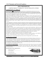
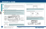
NOTICE TO USERS, INSTALLERS, AUTHORITIES HAVING
JURISDICTION, AND OTHER INVOLVED PARTIES
This product incorporates field-programmable software. In order for the product to
comply with the requirements in the Standard for Control Units and Accessories for
Fire Alarm Systems, UL 864, certain programming features or options must be limited
to specific values or not used at all as indicated below.
Program
Feature or Option
Permitted in
UL 864 (Y/N)
Possible
settings
Settings permitted in UL 864
Alarm Automation
Heartbeat Signal
Frequency:
Serial or IP
Y
0-90
As configured by UL 1981
Central-Station Automation
Systems Requirements
Data Type:
Y
Security, GPS, USDI,
Others in pull down menu
Security
Old Alarm Delivery
Options
Y
All, Subscriber controlled
Never
Radio Packet Life
Y
0-99
All
0 – No Time Out for Alarm, Trouble
or Restoral
Notes:
For Alarm Automation references throughout this manual,
Alarm Automation output must be connected to a
UL 1981 Listed Alarm Automation System
For UL Central Station Burglar Alarm applications,
Opening/Closing Signals shall be sent using an alternate communication
means that provides for premises acknowledgement (ring back)
This product shall be installed in accordance with NFPA 72,
NEC, UL 827 and all applicable local codes
For compliance with UL Central Station Burglar Alarm applications,
a workstation is required to be able to determine subscriber status.
The workstation shall be UL Listed ITE equipment.
40-7705I-UM
Page 2
Rev 5 July 9, 2010
AES 7705i MultiNet Receiver
Table of Contents
1.0
Product Description:............................................................................................... 6
1.1
About AES IntelliNet: ........................................................................................... 6
1.2
MultiNet Receiver: ................................................................................................ 6
1.3
7170 IP-Link Transceivers: ................................................................................... 7
1.4
Document Conventions: ........................................................................................ 7
2.0
Safety Considerations:............................................................................................ 9
3.0
Technical Specifications: ........................................................................................ 9
3.1
Front Panel:.......................................................................................................... 10
3.2
Rear Panel:........................................................................................................... 12
4.0
Installation and Setup : ........................................................................................ 14
4.1
Software Installation: ........................................................................................... 15
5.0
System Startup and Access: ................................................................................. 19
5.1
1st Time Notes:..................................................................................................... 19
5.2
Power up:............................................................................................................. 19
5.3
Power Down - Information:................................................................................. 20
5.4
Local Access and Login: - Initial Setup .............................................................. 20
5.5
Linux Command line:.......................................................................................... 21
5.6
Common Linux Commands: ............................................................................... 21
5.7
The GUI Desktop and the AES Menu:................................................................ 22
5.8
Start the Terminal Program: ................................................................................ 23
5.9
Setting Time: ....................................................................................................... 24
5.10 Synchronizing Time: ........................................................................................... 24
5.11 Time Zone: .......................................................................................................... 24
5.12 Review your TCP/IP Configuration: ................................................................... 25
5.13 Factory Default TCP/IP Settings ......................................................................... 25
5.14 Suggested TCP/IP Settings for Second MultiNet Receiver................................. 26
5.15 A note on DHCP.................................................................................................. 26
5.16 Configure TCP/IP, Linux Network Configuration:............................................. 26
5.17 Testing TCP/IP Configuration:............................................................................ 29
5.18 User Logout from directly attached keyboard & monitor: .................................. 30
5.19 User Logout from Workstation Access: .............................................................. 30
40-7705I-UM
Page 3
Rev 5 July 9, 2010
6.0
Admin GUI for Configuration and Administration:......................................... 31
6.1
Server Configuration ........................................................................................... 33
6.2
Define Business Units: (you must have at least one) .......................................... 34
6.3
Add a Business Unit – Alarm Automation Settings. ........................................... 37
6.4
Business Unit Overview ...................................................................................... 42
6.5
Modify a Business Unit ....................................................................................... 43
6.6
Subscriber Database Setup .................................................................................. 44
6.7
Alarm Data .......................................................................................................... 47
6.8
Close Your Browser When Finished With Admin GUI:..................................... 48
7.0
Workstation Access and Login:........................................................................... 49
7.1
Programs for Access Via a Workstation.............................................................. 49
7.2
Installing VNC Viewer:....................................................................................... 50
7.3
Using VNC Viewer: ............................................................................................ 51
7.4
After login: .......................................................................................................... 52
8.0
MultiNet Receiver Programs and Utilities: ........................................................ 53
8.1
MultiNet Specific Programs: ............................................................................... 53
8.2
MultiNet Utility Programs and Scripts:............................................................... 54
8.3
Special Purpose Circuits:..................................................................................... 56
8.4
AES Menu in the GUI Desktop:.......................................................................... 57
9.0
Managing Users: ................................................................................................... 58
9.1
Adding a user:...................................................................................................... 58
9.2
Retrieving user Display Number and Password:................................................. 58
9.3
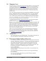
Changing a user’s Password:............................................................................... 59
9.4
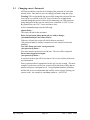
Change Admin GUI Access - Username and Password:..................................... 60
9.5
Deleting a User: ................................................................................................... 60
9.6
Test new user login:............................................................................................. 61
10.0
Admin GUI Database Functions:..................................................................... 62
10.1 Subscriber Overview ........................................................................................... 62
10.2 Routing Table Screen: ......................................................................................... 63
10.3 IP-Link Status Screen: ......................................................................................... 64
10.4 Get Signal History: .............................................................................................. 64
10.5 Close Your Browser When Finished With Admin GUI:..................................... 65
11.0
IPLinkCtrl (ipctrl) Network Management Software:.................................... 66
11.1 IPCtrl Function Groups: ...................................................................................... 67
40-7705I-UM
Page 4
Rev 5 July 9, 2010
11.2 Common data entry/selection menus and pop-ups:............................................. 67
11.3 Using the pick list pop up to Select a Subscriber ID ........................................... 68
11.4 Selecting a Route for Communication with a Subscriber Unit ........................... 68
11.5 The Message Function Group: ............................................................................ 69
11.6 Control Function Group....................................................................................... 71
11.7 Programming Function Group:............................................................................ 74
11.8 Data Radio Function Group:................................................................................ 86
11.9 System Function Group ....................................................................................... 90
11.10 Interpreting Screen Messages.............................................................................. 91
12.0
Operation............................................................................................................ 92
12.1 Manual Operation ................................................................................................ 92
12.2 Automatic Operation ........................................................................................... 92
13.0
Warranty and Service Procedure: ................................................................... 93
APPENDICES ................................................................................................................. 94
Appendix A Common Linux Commands ..................................................................... 95
Appendix B Server-generated LCD Display Messages. .............................................. 96
Appendix C Software installation Instructions............................................................ 98
Appendix D Sharing the Serial Port with additional Business Units......................... 99
Appendix E Alarm Output Codes Produced by the MultiNet receiver................... 101
Appendix F Printer Messages Produced by the MultiNet receiver.......................... 111
40-7705I-UM
Page 5
Rev 5 July 9, 2010
1.0 Product Description:
This document discusses the installation, configuration and use of the various
programs and hardware in the AES MultiNet Receiver uses. This Receiver is the
heart of the AES MultiNet system. All properly configured 7170 IP-Link
Transceivers (see section 1.4) will send their received AES●IntelliNet packets to
this Receiver via TCP/IP over a LAN, WAN, the Internet or if necessary and
equipped, via Modem (as backup), for distribution to the appropriate application
or external system.
1.1 About AES IntelliNet:
AES IntelliNet is a two-way data radio network for the monitoring of alarms or
transmission of specialized data packets. It is faster and more reliable than
telephone and cellular systems, which are subject to both tampering and general
failure. Phone lines may still be used for backup.
What makes the patented AES system unique are its “smart” radio
communicators, called subscriber units. Each subscriber unit is connected to an
alarm panel or specialized data port. Alarm information or data is transmitted by
radio to the central receiver or an “IP-Link Transceiver” (see section 1.4). If a
subscriber unit is too far away to reach the central station or an IP-Link
Transceiver directly, its message is relayed by another subscriber unit closer to or
in better communication with the central station or other closer units. This unique
built-in “repeater” capability creates a highly rugged, adaptive security network.
The system adjusts itself to forward messages by the shortest and best available
route. The “smart routing” capability is completely automated, with no special
programming needed. Also, by eliminating the need for dedicated repeaters and
towers, the AES system dramatically reduces the cost of setting up and operating
a wireless monitoring system.
1.2 MultiNet Receiver:
The AES 7705i MultiNet Receiver with integrated PC, Linux operating system
and IP-Link programs is housed in a 19” rack mountable enclosure. This device
acts as the central receiver. It is a specialized Linux based server with specific
programs running that acquire data packets from one or more IP-Link
Transceiver(s). AES Linux server software reads subscriber data from these IPLink transceivers via a TCP/IP socket connection. The server programs
categorize the incoming data and forward it to customer systems for further
processing. An example of this activity is alarm processing, where the server
software identifies an alarm received by an IP-Link, sent by a Subscriber attached
to an alarm panel, processes it, then forwards an alarm message to a customer’s
alarm automation software.
The software installation consists of several AES programs that process the data
and a web-based GUI for server administration and subscriber configuration. The
AES programs rely on open system components, including the Apache web server
with php, and the MySQL database, to process the subscriber data.
40-7705I-UM
Page 6
Rev 5 July 9, 2010
Other programs in the MultiNet receiver evaluate and distribute the data to an
appropriate application on this machine or another located on the LAN, WAN or
Internet. These other applications may re-distribute the data, store it in a database
for later retrieval, send it out a local RS232 serial COM port, send it out a printer
port or perform whatever function the application is designed. A single MultiNet
Receiver can have multiple IP-Link Transceivers installed locally or anywhere
connected by a TCP/IP connection. This capability allows the IntelliNet network
to be expanded virtually to any location desired that is serviced by the LAN,
WAN or Internet.
1.3 7170 IP-Link Transceivers:
These units communicate to the MultiNet Receiver via a direct Ethernet
connection, LAN, WAN or the Internet. Models have an integrated Modem to
communicate using a phone line if the TCP/IP connection is down. The IP-Link
acts much like a subscriber that re-transmits its received data packets via the
TCP/IP connection rather than via an RF transmission. This allows the IP-Link
Transceiver to be located outside of RF communication with a central station
receiver and the expansion of the IntelliNet system into previously unreachable
locations. They should be installed with the same care that a central station
receiver would as they are usually the primary path to the central receiver
location. Multiple IP-Link Transceivers can be installed in a single RF cloud to
act as backup or to provide multiple paths for subscribers in a geographical area.
Each IP-Link Transceiver can operate at the same frequency or at another.
Operating at other frequencies allows for an overcrowded region to get a new
clear frequency and still be able to be managed by the same receiver. It also
allows the expansion into other regions, states, countries or islands where
regulations may require operation at a different frequency than your other IP-Link
Transceivers.
1.4 Document Conventions:
<Key>
Characters between angled brackets refer to a specific key on the
keyboard.
Example <Enter> means to press the Enter Key.
{variable}
Characters between these braces refer to a value that will vary
dependant on any number of circumstances or configurations.
Example: {username} means to replace {username} with the
appropriate user name.
Example 2: {IP Address} would require a valid IP address be
typed in place of the label.
[Screen Text] Square brackets have several uses. Occasionally refers to a
Graphical Button, usually selected by clicking on the screen
graphic.
Also used to indicate a selection available by choosing from an
available list.
May also be used to show actual characters displayed.
40-7705I-UM
Page 7
Rev 5 July 9, 2010
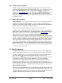
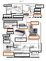
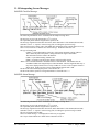
Typical MultiNet System
It is highly recommended and required for UL systems that a redundant MultiNet
Receiver be operational at the head end and that any location of 7170 IP-Link
Transceivers have at least two for the purpose of redundancy.
40-7705I-UM
Page 8
Rev 5 July 9, 2010
2.0 Safety Considerations:
All equipment must be installed in accordance with National Electric Code,
applicable UL Standards and local building codes. Unplug power before opening
enclosures to avoid electrical shock.
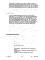
3.0 Technical Specifications:
The 7705i is in a standard 2U 19” rack enclosure configuration.
Operating voltage:
120 VAC, 60 Hz. +/- 10%
Operating current:
0.6 Amps
Operating Temperature Range:
13° to 35° +/-2 C
55° to 95° +/-3 F
Storage temperature Range:
-10° to 60° C
4° to 140° F
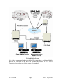
40-7705I-UM
Power Consumption:
200-Watts Maximum
Physical Dimensions:
19”Wide X 3.5” High (2U) X 12.24
(13.25 including rack handles)
Minimum Rack Depth:
Approximately 16” to allow for
cables
and connectors.
Approximate Weight:
9 pounds
Encryption:
AES 128 Bit
Page 9
Rev 5 July 9, 2010
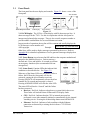
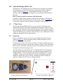
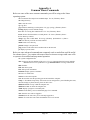
3.1
Front Panel:
The front panel has the user display and controls. Figure 3-1 shows a view of the
front panel.
Alert Sounder
DATE:
TO:
FROM:
RE:
Tactile Response Sounder
LCD Display
Power Button
Status Panel
Alert Panel
Figure 3-1
3.1.1 LCD Display: The LCD is a 4-line display with 20 characters per line. It
shows messages for the 7705i. Use this in conjunction with the Alert panel to
interpret and acknowledge messages. There is also a tactile response sounder to
provide audible confirmation of a successful button activation.
In most modes of operation, the top line will be constant and usually displays the
LCD firmware version number and
REV #.## (C) 2005-06 AES
AES copyright.
Example:
Other lines will be used to display messages generated by the server. Refer to
Appendix B for a detailed explanation of server-generated messages displayed on
the LCD.
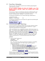
3.1.2 Power Button is used to turn On/Off and Reset the computer motherboard
integral to the MultiNet Receiver. Push to start up a
downed unit. Press and hold for 10 seconds to perform
an emergency shutdown (Not recommended for nonemergencies).
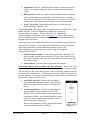
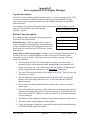
3.1.3 Status Panel: Contains LEDs that indicate fault
conditions as described below: See Figure 3-2.
When any of the Status LEDs are activated to reflect a
failure, the LED on the Alert panel will also be
activated, causing the Alert Sounder to activate.
Pressing SILENCE will momentarily silence the Alert
Sounder for 30 seconds until message is cleared.
Figure 3-2
Pressing ACKNOWLEDGE will clear the Alert LED.
The status LED will not be “cleared” until the failure
has been corrected.
• Receiver: Red Led - Indicates a hardware or system fault in the server.
These faults will include Printer Offline and LCD display faults.
• CPU: Red Led - Indicates that the CPU or internal processor has
performed a reset either manually initiated or automatically by the internal
watchdog circuit. Pressing the Acknowledge button turns off this LED.
• Ethernet: Red Led - Indicates a fault condition with the Ethernet
connection as detected by a missing check-in from a 7170 IP-Link
Transceiver.
40-7705I-UM
Page 10
Rev 5 July 9, 2010
•
Automation: Red Led - Indicates that the Alarm Automation process is
unable to get Acknowledgements from a designated alarm monitoring
system.
•
RF Interference: Red Led - Indicates that an RF interference condition
exists and that signals may be hindered. RF interference is a condition
where the Carrier Detect (CD) in the transceiver is active for more than 20
seconds. This LED will turn off if CD turns off for 100 milliseconds.
•
Power: Green Led - Indicates that proper power is detected at the
monitored points within the 7705i.
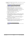
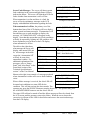
3.1.4 Alert Panel: This section of the front panel contains an LED and two Push
Button Switches. The LED illuminates to indicate the existence of
unacknowledged message(s). The switches allow for Silencing and
Acknowledgment as described below: See Figure 3-3. There is also an audio
device associated with these functions, which is located behind the small hole to
the right of the Alert Panel.
A message queue exists within the MultiNet receiver to hold messages that are in
need of a user’s response. A user must acknowledge these messages manually
when alarm automation is offline and that automation system is not
acknowledging the reception of those messages using the configured
communication protocol.
•
Tactile Response Sounder: A short beep sound will be heard from the
tactile response sounder located near the LCD any time a button press in
this panel is accepted. There may be a short delay between the press and
the sounder’s beep.
•
Silence Button: Is used to silence the internal alert sounder.
If the Silence Button does not silence the Alert Sounder, it may be due to an
overheating condition. Other MultiNet Receiver functions may appear normal.
The unit must be shut down and the cause of the overheating condition must be
corrected before continued use. To shut down the unit, press the Power Button on
the front panel for 10 seconds or switch the power switch on the rear panel to the
Off position. Contact AES for service
•
Alert LED: Red Led - Indicates that a condition
exists that needs attention or that the CPU LED is on.
Refer to the Alert messages on the LCD display for
details.
•
Acknowledge Button: Is used to Acknowledge the
message that is currently displayed on the LCD
Display. This is a function that is only required when
automation is offline. Once acknowledged the current
message is removed and the next message (if any) in
the message queue is displayed.
When alarm automation is online, pressing this button
will turn an illuminated Alert LED off.
40-7705I-UM
Page 11
Figure 3-3
Rev 5 July 9, 2010
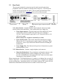
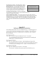
3.2
Rear Panel:
The rear panel contains the connectors used to attach external connections,
peripherals such as the monitor, keyboard, mouse and power. The main power
switch is also located on the rear panel. The rear panel is divided into at four
sections as outlined below. Figure 3-4 shows a view of the rear panel.
Power Section
Modem
Single Board Computer Connection Section
Printer Port
Figure 3-4
3.2.1 Power Section: Contains the power input connector and power supply
On/Off switch as described below: Also contains the Power Supply fan.
•
Power input connector: Plug the female end of the supplied AC power
cord into this connector and the male end of the power cord into a
120 VAC, 60 Hz receptacle supervised by a UL Listed 864 UPS or a UL
1481 power supply.
Do not connect to a receptacle controlled by a switch.
•
Power On/Off switch: This switch controls the internal power supply.
When in the off ( O ) position power supply output is interrupted. When
in the On (| ) power is provided to the internal electronics including the
motherboard.
•
Power Supply Fan: This fan must be kept clear of obstructions to permit
unobstructed flow of air.
3.2.2 Modem Section: Contains a single telephone jack connector:
•
Phone line/Modem Jack: Plug a telephone cord into this connector with
the other end plugged into an active telephone Jack. This is used to
provide a backup Modem connection for IP-Link Transceivers that cannot
communicate via the Internet or TCP/IP.
When connecting the 7705i MultiNet Receiver’s modem to a telephone line, use only 26
AWG or larger wire. A UL Listed 497A Secondary Protector is required to be installed
on the incoming lines. Installation shall be in accordance with the NEC Article 800, the
manufactures installation instructions and in accordance with all local codes.
40-7705I-UM
Page 12
Rev 5 July 9, 2010
3.2.3 Single Board Computer Connector Section: Contains connectors for computer
peripherals.
•
Serial Port 1 / (COM 1) Upper: [/dev/ttyS1] Typically used to connect to
alarm monitoring system for signals communicated via RS-232.
See Appendix E for a list of Alarm messages generated.
•
Serial Port 2 /(COM 2) Lower: Unavailable. Not Used.
•
Monitor, CRT (J8): Plug the video monitor into this Jack. ¿
•
Ethernet Port 1 (J10) [eth0]: Can be used for a dedicated crossover
Ethernet cable connection to a 7170 IP-Link transceiver using no
additional network hardware or as a connection to an Ethernet Hub/Switch
using a standard straight through Ethernet cable.
Pre-configured factory default to static IP address 192.168.0.101.
•
Ethernet Port 2 (J11) [eth1]: This Port is not used.
•
USB ports 0 & 1 (0 is Lower): Not Used
•
PS/2 Keyboard/Mouse port (J16): ¿ Use supplied Y-cable to connect a
PS/2 keyboard and a mouse. These devices are used during configuration.
Once configured access to the MultiNet Receiver is done through a
network workstation.
•
Reset Switch: Press and hold for 2 seconds to perform a hard reset. Do
this only in the event of a lockup condition when proper shut down
procedure cannot be accomplished.
3.2.4 Printer Port Section: Contains a single printer connector:
•
Printer Port: Plug the Db-25 male end of the printer cable connected to a
supported parallel printer. Attach only a printer Listed by UL for
“Signaling use” under UL 864, such as an AES 75-0101.
See Appendix F for a listing of generated messages.
Note: ¿ These are to be used for initial setup only and are not to remain
connected.
40-7705I-UM
Page 13
Rev 5 July 9, 2010
4.0 Installation and Setup :
A separate “Initial Installation and Setup Guide” is provided to
guide you through the initial installation and setup.
A standalone Receiver requires a monitor, keyboard and mouse for user interface.
See Figure 4-1. The standalone configuration is not recommended by AES
Corporation for anything other than initial setup and preliminary testing of the
system. Once properly configured and connected to a LAN, a network
workstation is used to access and configure the receiver remotely. See Figure 4-2
and Figure 4-3.
A printer is also required for printing any output directed to the printer port.
Refer to Appendix F for a listing of printed messages. Ethernet port(s) are
integrated into the PC, and are used to connect to the IP-Link Transceiver(s) and
external applications on remote servers or systems via direct connection, LAN,
WAN or the Internet.
A system, while it may not have a keyboard, video monitor or mouse
connected during normal operation, will require these peripherals connected
directly for initial setup until remote access is accomplished. They may also
be needed later for occasional configuration modifications.
The 7705i, monitor and any network related equipment shall be connected to a
suitable UL-UPS to maintain power during power outages.
In a Dual system, each 7705i and the 7170 IP-Link Transceiver shipped, is
configured exactly the same. At least one set must be modified to operate the two
pairs together in the same TCP/IP network. Each device in the system must have
unique TCP/IP addresses. Each 7170 must have a unique Unit ID for the
IntelliNet Network it will operate in.
Figures 4-1, 4-2 & 4-3 on next pages illustrate some typical system installations.
The illustration on page 8 also illustrates a typical system.
40-7705I-UM
Page 14
Rev 5 July 9, 2010
Notes:
•
•
•
•
•
•
•
Power Line, router/ switch, and telephone connections shall not leave the
room where the AES equipment is installed. This must be accomplished
by co-locating outlets and interfacing equipment in the room where AES
equipment resides.
7705i must be installed in a UL Listed metal rack-mounting cabinet that
complies with UL864. The cabinet must be provided with integral outlets
and the ability to connect AC input via conduit. All wiring exiting the
cabinet must be in electrical conduit. Be sure non-power limited and
power limited wiring are separated by at least 1/4 inch.
All equipment shall be connected to a UL Listed UPS (UL 864) or UL
1481 power supply. In addition, the central station shall have a generator
to maintain power for the receiving equipment and environmental
controls for a period up to 24 hours or longer.
A UL Listed UPS or generator to supply 24 hours of standby must be
installed and utilized at the monitoring station. If the primary power
source at the monitoring station is lost or otherwise faulted, this condition
must be obvious to the operator on duty.
Equipment Location: A UL 7705i MultiNet Receiver must be
installed in a room where operators can properly hear the Audio Alert
Sounder.
When connecting the 7705i MultiNet Receiver’s modem to a telephone
line, a UL Listed 497A Secondary Protector is required to be installed on
the incoming lines. Installation shall be in accordance with the NEC
Article 800, the manufactures installation instructions and in accordance
with all local codes.
When connecting the 7705i MultiNet Receiver’s Ethernet ports to a
network, a UL Listed 497B Secondary Protector is required to be
installed on the Ethernet cable. Installation shall be in accordance with
the NEC Article 800, the manufactures installation instructions and in
accordance with all local codes.
4.1 Software Installation:
All necessary software is pre-installed on your 7705i.
If your system has a catastrophic failure it may require the reinstallation of the
Linux operating system and the specialized IP-Link software programs. BIOS
settings should also be checked to confirm that the unit would initialize and
operate properly. Routine backing up of the databases to another storage device
would be essential in any successful reinstallation or recovery process.
Contact AES Technical Support if you need assistance with software installation
or BIOS settings.
40-7705I-UM
Page 15
Rev 5 July 9, 2010
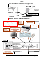
Figure 4-1
Single MultiNet Receiver Connections to a 7170 for Initial Setup
Local
16.5 Volt AC
Transformer
Default IP Address = 192.168.0.11
Intended for initial Setup and testing ONLY
This configuration is used for initial
setup only! Monitor, Keyboard and
Mouse not to be left connected
during normal operation.
Customer
Provided
TELCO Line
Optional
Internet
Connection
Customer Provided
Ethernet Router
See Appendix F for
printed messages
Customer provided
peripherals, or
purchased separately
from AES.
Monitor
Keyboard
AC Power
Alarm Monitoring
See Appendix E for messages
40-7705I-UM
Mouse
Y Cable
Default IP Address Port 1 = 192.168.0.101
Default IP Address Port 2 = 10.0.1.221
Page 16
Rev 5 July 9, 2010
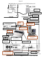
Figure 4-2
Dual MultiNet Receiver Connections to Local 7170 IP Links thru a LAN
AES Part Number
52-0054
EMR Corp
Model 65610
Local
16.5 Volt AC
Transformer
Default IP Address = 192.168.0.11
UL 497B Surge
Protector
2nd Local 7170
as shown above.
UL 497B Surge
Protector
Suggested Address = 192.168.0.22
Optional
Internet
connection
2nd 7705i Receiver as shown
below. For redundancy.
Customer Provided
UL Ethernet Hub
UL 497B Surge
Protector
See Appendix F for
printed messages
Suggested IP Address = 192.168.0.102
Customer Provided
TELCO Line
UL 497A Surge
Protector ¹
C/S Generator
Customer provided
Workstation
7705i
UL UPS
MultiNet Receiver
UL AC Power
Surge Strip
NFPA 72 Type 6
UL 497B Surge
Protector ¹
Alarm Monitoring
See Appendix E for messages
.Not investigated by UL
40-7705I-UM
Default IP Address Port 1 = 192.168.0.101
Default IP Address Port 2 = 10.0.1.221
Page 17
¹ SINGLE POINT GROUND TO 7705i
Rev 5 July 9, 2010
Figure 4-3
Dual MultiNet Receiver Connections to Remote 7170 IP-Links thru Internet
nd
Remote
2 Remote 7170
Default IP Address
192.168.0.11
Consult with IT Dept.
16.5 Volt AC
Transformer
UL 497B Surge
Protector
Acquire IP Addresses
from IT Dept.
UL 497B Surge
Protector
Off Site Remote Location
Customer Provided
UL Ethernet Hub
Internet
Head End - Location of 7705i MultiNet Receivers
Acquire IP Address from IT Dept.
Customer Provided
UL Ethernet Hub
nd
2 7705i Receiver as shown
below. For redundancy.
UL 497B Surge
Protector
See Appendix F for
printed messages
Customer Provided
TELCO Line
UL 497A Surge
Protector ¹
C/S Generator
UL UPS
UL AC Power
Surge Strip
7705i
MultiNet Receiver
UL 497B Surge
Protector ¹
Alarm Monitoring
See Appendix E for messages.
Not investigated by UL
40-7705I-UM
Customer provided
Workstation
Default IP Address Port 1 = 192.168.0.101
Default IP Address Port 2 = 10.0.1.221
Acquire final IP Addresses from IT Dept.
Page 18
¹ SINGLE POINT
GROUND TO 7705i
Rev 5 July 9, 2010
5.0 System Startup and Access:
AES ships the 7705i MultiNet Receiver with the Linux operating system and IPLink programs pre-installed and with basic configuration already complete to
operate as shown in Figure 4-1. Each installation will have site-specific
parameters that would typically be changed or entered during initial installation
and setup.
Refer to separate guide for assistance with initial setup.
Familiarity with the Linux operating system will be necessary to run programs
that operate, control and configure your IP-Link system. Refer to Appendix A for
a list of some common Linux commands you might use in this process.
5.1
1st Time Notes:
The first time that the MultiNet Receiver is powered up, it will require some
configuration specific to the unique installation environment in which it is to be
used. A directly attached keyboard, monitor and mouse will be needed to perform
this configuration. Refer to separate Initial Installation and Setup Guide. Do not
connect the Ethernet ports to an active network until you are confident the TCP/IP
settings are appropriate for the target network.
5.2
Power up:
If this is a standalone system, or if you are still configured for initial setup as
shown on Figure 4-1 with an attached keyboard, monitor and mouse, turn on
power of the attached video monitor.
Switch the power of the 7705i to the on position. The main switch for the power
supply is on the back panel. This must be switched to on first. Then if the startup
process does not automatically begin, push the Power push button Switch on the
front panel to initiate the startup process.
Once the startup process has begun, the 7705i MultiNet Receiver will initialize,
going through its normal boot sequence executing the programs defined in the
configuration files. Password protected remote access through VNC is factory
configured. Web access to the Admin GUI, which is an html-based interface,
should be available after a proper startup, assuming the network settings are
properly configured for the receiver’s attached network.
Section of Rear Panel of Receiver
40-7705I-UM
Section of Front Panel of Receiver
Page 19
Rev 5 July 9, 2010
5.3
Power Down - Information:
The power to the 7705i should not just be removed without going through the
proper shut down procedure.
DO NOT REMOVE POWER OR TURN OFF POWER of the 7705i
MultiNet Receiver WITHOUT USING THE PROPER SHUT DOWN
PROCEDURE!
This receiver is a Linux server and improper shut down could damage files and
prevent operation. There are several ways to shut down a Linux server. Linux
provides a command named “shutdown ” to perform this function.
● To shut down a MultiNet receiver, enter the following command from a
command line prompt:
shutdown –h now<Enter>
Or
● To shut down a MultiNet receiver from the GUI, right click on the desktop and
select “Shutdown Server!”
5.4
Local Access and Login: - Initial Setup
Local access means to operate the MultiNet Receiver using a keyboard, monitor
and mouse that are connected directly to the back of the Receiver. Login is
required to operate the Receiver in this manner.
After a successful power-up, you should be presented with the login prompt “aes
login:” You may have to press <Enter> after the boot up process to get the actual
login prompt. Note the lines at the top of the display in Figure 5-1. They are
typically the last lines seen before the login prompt on the display for a normal
boot up. Press <Enter> after these lines are displayed if the “aes login” is not
displayed. For Super user Administrator functions you need to login as root
using the current password. The factory default password for user root is
peabody2.
•
At the “aes login” prompt, type
root<Enter>
then
peabody2<Enter>.
Note: After initial setup, if the password has been changed, as it should be,
use the current password for user root to login to perform setup and
configuration functions.
○
Be sure to log out when finished. See “User Logout”
○
The user root is the most powerful Super user in a Linux server.
Do not leave the system unattended when logged in as root!
○
User root should only be used to perform administrative functions!
○
To prevent unauthorized access – change default passwords as
described in “Managing Users”, section 9.
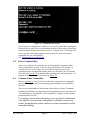
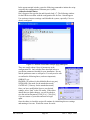
When the startup and login process is complete, you should be presented with the
command prompt “[root@aes root]#”. See Figure 5-1 below. Enter key may need
to be pressed before the prompt is actually displayed.
40-7705I-UM
Page 20
Rev 5 July 9, 2010
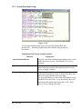
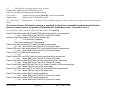
Figure 5-1 Command Line Screen
If your system’s configuration is a dual UL or a non-UL system that is configured
for remote access only, then your installation most likely does not or will not have
a directly attached keyboard, monitor or mouse. Connect to the 7705i using VNC
Viewer or your workstation program as instructed by the person or persons
responsible for your configuration.
See “Workstation Access and Login:”
5.5
Linux Command line:
After a successful local access login, you would normally be presented with a
Linux Command line prompt. If you are using the Desktop GUI interface, as
would be the case from a remote access session, and want to enter Linux
commands from a command line prompt, then you will need to start a Terminal
shell. Refer to section 5.8 for information on starting the Terminal program. An
example of the Terminal screen is shown in Figure 5-3.
5.6
Common Linux Commands:
Refer to Appendix A for a list of some of the more common Linux commands
you may be using with the Linux operating system installed on your MultiNet
Receiver.
There is also an abundance of information on the subject of Linux Commands,
available on the Internet to supplement any documentation you may already have.
You could begin by searching for “Linux commands” using any of the common
search engines or services.
Use extreme caution when attempting to use any Linux command on
your MultiNet system as the consequences could have unexpected
results, disrupt normal system operation or cause permanent possibly
irreparable damage.
40-7705I-UM
Page 21
Rev 5 July 9, 2010
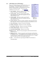
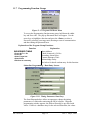
5.7
The GUI Desktop and the AES Menu:
Note: Access to this menu must be password protected for supervisors control only.
The Linux GUI Desktop used in the AES MultiNet Receiver is the Motif Window
Manager (MWM). It is configured as a blue screen with no icons. The normal
mouse curser is a white trimmed black “X”. If you loose or unintentionally close
the MWM, you can restart it by typing the following command at a command
prompt:
startx<Enter>.
If you connect using VNC Viewer access, this is the interface you will be
presented with after a successful connection.
To access a menu of functions, right click on the desktop and hold. While
holding the right click, move the curser, which is now an arrow, over the menu
items. Individual menu items will highlight as the curser passes over. To select
an item either release the right click while the desired menu item is highlighted or
left click on the item while still holding the right click.
From the GUI Desktop, you will be able to start programs used to perform
configuration, maintenance and other user functions.
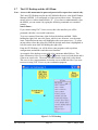
An example of the desktop screen with a few comments added follows. The
figure illustrates a false view as the and mouse cursers are both shown and it
is not to an actual scale. The menu available from the right click is also shown.
This view is also a representation of what the screen would look like if you were
to access it using VNC Viewer as your workstation program.
Figure 5-2 GUI Desktop
40-7705I-UM
Page 22
Rev 5 July 9, 2010
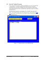
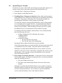
5.8
Start the Terminal Program:
Some of the utilities needed to configure the MultiNet receiver are accessed from
a command line. A terminal emulator program named xterm is an offered
selection from the AES menu available by use of the right click on the desktop.
The terminal program provides a command line, which can be used to run utilities
mentioned above.
Start the terminal emulator by selecting the “New Terminal” item in the AES
Menu. The terminal window in the GUI desktop screen is shown below in Figure
5-3. This is also a view using VNC Viewer from a remote PC that has access to
the MultiNet receiver.
Figure 5-3 Terminal window on the MWM Desktop
40-7705I-UM
Page 23
Rev 5 July 9, 2010
5.9
Setting Time:
Time is very important and somewhat complex in a MultiNet System. Use the
Linux date command to set the time as shown in one of the following examples:
Where
hh = hour
MM = month
mm = minutes
DD = day
.ss = seconds
CCYY = 4 digit year
date MMDDhhmm.ss<Enter>
date MMDDhhmmCCYY.ss<Enter>
date 10031055.00
Sets the time to Oct 3, 10:55:00 AM using current year
For additional information on the date command, use:
man date<Enter>
Press Q to exit man program.
5.10 Synchronizing Time:
Contact AES Technical Support for options to synchronize two or more MultiNet
Receivers to the same time standard. This is important in any system where
servers share files.
5.11 Time Zone:
Time zone is also very important as time is kept internally in UTC and is set or
displayed according to a variable that identifies the Time Zone the MultiNet
receiver is located within.
By default, a MultiNet Receiver is typically set to Eastern Time Zone or
America/New_York.
The Setup program accessed by entering the setup command shown below on a
command prompt is the easiest utility to use for setting the time zone.
Setup<Enter>
You can also use the following utility, but Setup described above is usually easier.
Enter the following command to use the Time Zone Select utility:
tzselect<Enter> command to set the time zone. Follow instructions and answer
the questions presented on the screen.
Contact AES Technical Support for additional information on adjusting the Time
Zone on your MultiNet receiver.
40-7705I-UM
Page 24
Rev 5 July 9, 2010
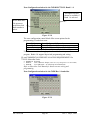
5.12 Review your TCP/IP Configuration:
The TCP/IP parameters of all TCP/IP devices must be properly configured in
order for the MultiNet Receiver to communicate with any local or remote IP-Link
Transceiver(s), and any other TCP/IP devices it needs to communicate with.
As stated before, if you are connected as shown in Figure 4-1 using the 7170 that
was shipped with your receiver, then no configuration is needed for the pair to be
operational.
There are two Ethernet adapters incorporated into the MultiNet Receiver. One is
identified as eth0 the other as eth1. You can issue the Linux command ifconfig
at a command prompt to review the TCP/IP settings. It is best to request IP
information one adapter at a time. Enter the following to view Port 1 settings:
ifconfig eth0<Enter>
Review the data on the screen. Then, to review the settings of Port 2, the second
adapter, enter the following:
ifconfig eth1<Enter>
You can scroll the screen display to view information that has scrolled off by
using the <Pg Up> and <Pg Dn> keys.
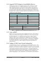
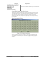
5.13 Factory Default TCP/IP Settings
The table below shows the factory default settings of all TCP/IP devices in a
MultiNet Receiver / 7170 IP-Link transceiver pair. Both Receivers and IP-Link
Transceivers in a dual system are configured the same from the factory. You
MUST modify the TCP/IP settings of the second Receiver and IP-Link
Transceiver before the two can be connected together in the same network. If the
new MultiNet system is being placed in a network that has existing MultiNet
devices then these new devices need unique settings.
Failure to do so will result in conflicts.
7705i Default Ethernet Port Settings
Parameter
Ethernet Port 1 / eth0
Ethernet Port 2 / eth1
ONBOOT
Yes
Yes
BOOTPROTO
STATIC
STATIC
IPADDR
192.168.0.101
10.0.1.221
NETMASK
255.255.255.0
255.255.255.0
GATEWAY
192.168.0.1
10.0.1.7
7170 IP-Link Transceiver Default Ethernet Port Settings
IP Address
192.168.0.11
GATEWAY
192.168.0.1
NETMASK
255.255.255.0
Table 5-4 Factory default TCP/IP settings
40-7705I-UM
Page 25
Rev 5 July 9, 2010
5.14 Suggested TCP/IP Settings for Second MultiNet Receiver
The table below shows some suggested settings for the TCP/IP devices in the
second MultiNet Receiver / 7170 IP-Link Transceiver pair of a dual system.
These suggestions should be appropriate for a network that is only made up of
devices from a MultiNet System. If you are connecting to an existing network
you must get these values from the administrator of that network. Failure to get
the proper values could prevent proper operation of the MultiNet devices or other
existing devices on the network.
Second 7705i/ Suggested Ethernet Port Settings
Parameter
Ethernet Port 1 / eth0
Ethernet Port 2 / eth1
ONBOOT
Yes
Yes
BOOTPROTO
STATIC
STATIC
IPADDR
192.168.0.102
No Suggestion
NETMASK
255.255.255.0
255.255.255.0
GATEWAY
192.168.0.1
10.0.1.1
Second 7170 IP-Link Transceiver Suggested Ethernet Port Settings
IP Address
192.168.0.22
GATEWAY
192.168.0.1
NETMASK
255.255.255.0
Table 5-5 Suggested TCP/IP Settings for Second Receiver & 7170
5.15 A note on DHCP
DHCP is an acronym for Dynamic Host Configuration Protocol. This means IP
addresses are automatically assigned by a DHCP server on your network. Since
the MultiNet Receiver’s in a MultiNet system must have a unique static IP
addresses, a DHCP server would have to be configured to reserve and always
provide the same address to each specific receiver. Contact your IT department
for additional information. Do not use this option if you do not have a DHCP
server on your network, or cannot configure it to provide static addresses to
specific devices.
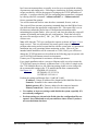
5.16 Configure TCP/IP, Linux Network Configuration:
As mentioned before, there are two Ethernet ports in the MultiNet receiver. The
port names are Ethernet Port 1 [eth0] and Ethernet Port 2 [eth1]. If you are using
both ports, you will need to enter the commands to configure each port separately.
Note that physical Ethernet connector labeled Port 1 is internally identified as
eth0 and that the Ethernet connector labeled Port 2 is internally identified as eth1.
This is due to a typical convention where components such as connectors are
numbered beginning at 1 and a programmers’ convention that usually begin at 0.
40-7705I-UM
Page 26
Rev 5 July 9, 2010
In a Linux environment there are usually several ways to accomplish the editing
of parameters and similar tasks. Following are instructions for using programs or
scripts provided by AES for the purpose of setting up the TCP/IP parameters of
each port. A script provided by AES for configuring these parameters is initiated
by entering either the command “./editnetworketh0” or “./editnetworketh1”
from a command line prompt.
You will be instructed when to enter the above command, for now, read on.
The script will first run some preparation commands then start the KWrite Linux
text editor and open the appropriate configuration file. This opened file is a text
file that must contain the proper lines of configuration information while
maintaining the original format. After you save and close the editor the script will
continue by initiating and testing the new configuration. Watch the left side of
the screen for messages such as [ OK ] or [ Fail ] indicating success or failure
of those tests.
Note: AES ships the 7705i, pre-configured to operate as shown in Figure 4-1 as a
single receiver. This is to assist those who want a quick setup to be able to
perform radio testing and to become familiar with the system prior to a permanent
installation into your operational alarm monitoring system. Later or if your
intended initial installation will be connected to a LAN, WAN, you will have to
change the TCP/IP parameters as described on the following pages to operate with
your LAN/WAN and Internet network environments.
Contact your IT department for assistance with these parameters.
For a simple installation where a crossover Ethernet cable is used to connect the
7170 IP-Link Transceiver directly to Ethernet Port 1 (J10), eth0 of a single or the
first 7705i MultiNet Receiver, the following settings in this receiver along with
the recommended settings in the 7170 manual should allow communication:
IPADDR=192.168.0.101
See Figure 4-1.
NETMASK=255.255.255.0
GATEWAY=192.168.0.1
Perform the settings on Ethernet Ports 1 [eth0] & 2 [eth1].
IP address: Unique IP address to be assigned to this MultiNet Receiver.
Netmask: Netmask for the connected network.
Default gateway (IP): Gateway address for the connected network.
Primary nameserver: Nameserver for the connected network.
•
Use caution, as incorrect settings could disable the system, especially if it
were already configured.
•
Previous settings are shown in the fields when the configuration files are
opened. Once edited and saved you could loose those values if you have
not recorded them elsewhere.
40-7705I-UM
Page 27
Rev 5 July 9, 2010
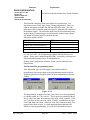
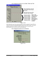
In the xterm terminal window, enter the following command to initiate the script
to modify the configuration of Ethernet port 1 (eth0).
./editnetworketh0<Enter>
Don’t forget to first type the dot and forward slash “./”. The following window
for the KWrite text editor with the configuration file for Port 1 should appear.
Use caution as incorrect settings could disable the system, especially if it were
already configured.
Figure 5-5 KWrite Text Editor with file ifcfg-eth0 Open
There are usually about 6 lines of parameters in the
configuration file. Only edit the lines described below to
provide the parameters needed for your installation. Do not
edit the parameter name or add spaces. You only need to edit
or confirm the following lines: (order not important)
ONBOOT=yes
IPADDR={IP address for this MultiNet Receivers port}
NETMASK={Net mask for the attached network}
GATEWAY={Gateway for the attached network}
Once you have modified the lines to your desired
settings, select “Quit” in the File menu. If the editor
detects that you made changes, you will be asked to
save the current Document. Click [Yes]. Click [No]
if you are unsure of your edits and want to begin
again.
Once the editor is closed the script will continue by initializing the new settings
and running a few tests. Watch the screen for errors.
40-7705I-UM
Page 28
Rev 5 July 9, 2010
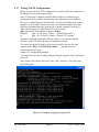
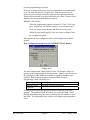
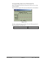
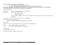
5.17 Testing TCP/IP Configuration:
Before you can test the TCP/IP configuration you need to make the connection of
the Ethernet Port(s) to the target network.
Once TCP/IP setup is complete and the Ethernet cables are connected to an
operational network, perform the following test to determine if your MultiNet
Receiver is working properly in the network. To test your settings, ping another
computer or device that is on your network. At a command prompt, issue the
following command replacing {network ID of another computer} with the IP
address of the gateway or other known PC on the network.
ping –c4{network ID of another computer}<Enter>
Example:
ping –c4 192.168.0.1<Enter> (Default Gateway PC)
or
ping –c4 192.168.0.11<Enter> (Default 7170 setting)
The above listed ping commands will ping 4 times (-c4), either the default
Gateway, or the 7170 assuming they are configured as listed.
You can even ping the IP address of the receiver itself to see how the ping
program works. Ping –c4 192.168.0.101<Enter> (Default Receiver)
If necessary you may press:
<Ctrl> + C to stop pinging attempts.
You should receive responses indicating how long the response took, if it failed or
timed out.
The example screen below shows the “ping –help” response, a successful ping
and a failed ping.
Figure 5-6 Example of a ping to a gateway PC
40-7705I-UM
Page 29
Rev 5 July 9, 2010
5.18 User Logout from directly attached keyboard & monitor:
You should log out the user that is logged in (usually root), when local access
using the directly attached keyboard, monitor and mouse, to your system is no
longer need. Depending on where you are and what you are doing the procedure
will vary. Several options are outlined below.
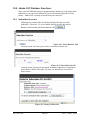
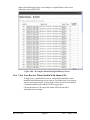
Option 1: Logout (preferred method)
With this option you will log out and go back to the aes login screen.
1. If you are at a command line prompt and not running the MWM GUI, then
go to step 3.
2. If you are in the MWM GUI, first select Quit… from the AES Menu.
Confirm by clicking OK or press <Enter>.
Select Quit… Menu item
Then click OK or press <Enter>
3. Enter one the following commands at the
command prompt:
logout<Enter>
or
exit<Enter>
4. The screen should return to the aes login prompt.
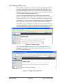
Option 2: Reboot server
1. The system will accomplish a logout when you reboot the MultiNet
receiver. This will restart the server stopping at the aes login screen.
Be careful if you are rebooting an active MultiNet Receiver as signals may
be processing and a reboot could delay or terminate that process. Other
users may also be connected and this will disconnect them possibly
interrupting their work or cause loss of data.
To reboot do one of the following:
a. From the command line prompt enter the following:
reboot<Enter>
b. From the MWM GUI, select the “Reboot Server!” item in the AES
Menu accessed by right clicking on the MWM desktop
Select Reboot Server! Menu item
2. This process should leave a properly configured MultiNet receiver and its
programs running allowing remote access by the super user root via VNC
on display 1, as well as any other users that were properly created.
5.19 User Logout from Workstation Access:
If you need or want to logout from the workstation access session, simply close
the program you are using to establish that access. For example: If using VNC
Viewer, close the program by clicking on the X in the upper right corner of the
VNC window. The password will be required the next time you attempt access.
40-7705I-UM
Page 30
Rev 5 July 9, 2010
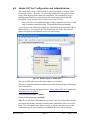
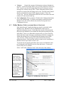
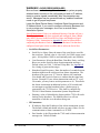
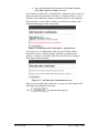
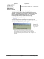
6.0 Admin GUI for Configuration and Administration:
The Admin GUI is a set of files located in a directory linked to “Admin” under
the Apache “htdocs” directory. To access this Admin GUI you need to connect
using a Web Browser from a network workstation. The Apache Web Server
running on the MultiNet receiver protects this connection with 128 Bit SSL
Encryption. Some possible URL’s used to access the GUI are:
http://192.168.0.101/Admin/home.php Using workstation to receiver 1 eth0
http://localhost/Admin/home.php Using attached keyboard/monitor.
To get access to the Admin GUI simply use a Web browser and enter the URL as
indicated above. Your actual URL may be different and will be the actual IP
address assigned to each MultiNet receiver in earlier steps.
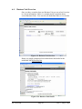
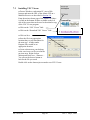
Fi
gure 6-1 Remote Login to Admin GUI
The correct URL takes you to the login window as seen above,
The correct username and password takes you to the main menu page (homepage)
of the Admin GUI.
To change the username and password see Change Admin GUI Access under the
Managing Users, Section 9.
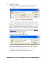
Factory default username = Admin
Factory default password = peabody
Note: If you check the “Remember my password” box, you will not have to enter
your password on future attempts from this same workstation, after a successful
login. This will significantly reduce security, as anyone who gets access to the
workstation may be able to modify your MultiNet Receiver Server settings.
40-7705I-UM
Page 31
Rev 5 July 9, 2010
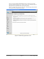
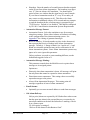
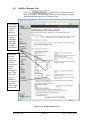
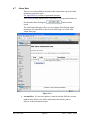
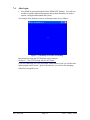
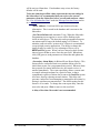
Once you get to the Admin GUI Homepage, there is a brief overview of the
functions available through the GUI. There are links in the left hand column of
this page and every page that can be used to select actions.
Below is a sample screen from the Admin GUI. The following sections describe
the functions of the Administration program.
Figure 6-2 Admin GUI program home screen
40-7705I-UM
Page 32
Rev 5 July 9, 2010
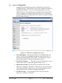
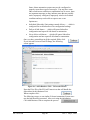
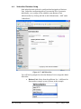
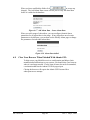
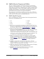
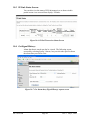
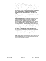
6.1
Server Configuration
Among the first parameters that must be configured are on the Server
Configuration page. AES ships the receivers pre-configured as indicated
throughout this manual. To review or edit the parameters, access the
Admin GUI Server Configuration screen as indicated above and click on
"Server Configuration" on the left hand side of the screen. This brings
you to the AES Server Configuration screen, where you modify as needed
the following parameters:
Figure 6-3 AES Server Configuration Screen
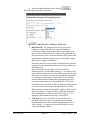
•
Server ID Number: Identification number of your MultiNet Receiver
(server). Unless you are running more than one server at your site, we
recommend using the default value of 0001. Use 0002 for the second.
Each needs a unique ID. Range is decimal 0001 to 9999.
•
IP-Link Port Number:
Port used by your IP-Link Transceiver(s) to
connect to the server. Default and suggested value is 7070.
•
Modem Device Path: Unix path used by the modem in your IP-Link
Transceiver. Default is “/dev/ttyS3”. Unless you are very well versed in
Linux and the hardware of this receiver, do not enter anything else here
unless directed by AES Technical or Engineering Support.
•
LCD Device Path: Unix path used by the LCD in your IP-Link
Transceiver. Default is “/dev/ttyS2”.
40-7705I-UM
Page 33
Rev 5 July 9, 2010
6.2
•
Verbose:
Controls the amount of information written to limited size
log files. A pull down menu allows you to set this parameter to Off, On or
Full. In most cases, the Off setting should be used, so that only critical
messages are written to the log files. If more information about system
operation is required, the On setting can be used. The Full setting should
only be used at the direction of AES support personnel. This is an
“Event” log. The more information stored on each event reduces the total
number of events stored in the log.
•
Set Configuration: When complete, Click the [Set Configuration] button
to save the configuration. If you have not already created at least one
Business Unit, you will be asked to do so before leaving the Server
Configuration screen.
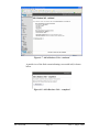
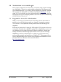
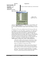
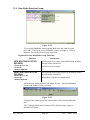
Define Business Units: (you must have at least one)
Each subscriber unit’s application data type must be associated with a
Business Unit. Business Units are defined based on the types of
application data they process. Each Subscriber must be associated with
the proper type Business Unit to handle the data packets produced by the
Subscribers. Since every Subscriber creates at the very least, Check-In,
Status and other routine messages, most Business Units have settings for
Alarm data and may have to be linked with the Business unit of Data
Type: Security, if those messages are to be monitored by an alarm
monitoring system. Each user that will have remote access would have a
Business Unit set up for their exclusive use.
To provide for site-specific particulars, there are no user Business Units
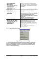
pre-configured in the MultiNet receiver from the factory. You need to
create at least one to continue.
Select “Add” under “Business Units” in the left side of the window.
If this is your
First Business
Unit, select this?
You can change it
later if necessary.
Do not select this
checkbox if this is
an additional
Business Unit that
will use the Serial
Port already
configured for use
by another
Business Unit.
40-7705I-UM
Figure 6-4 Add Business Unit Screen
Page 34
Rev 5 July 9, 2010
Some systems will only have one type of application data and one access
point, and thus will need to create only one Business Unit. If you have
multiple types of data and need multiple remote access locations, define a
Business Unit for each data type and or remote user. For example, if you
have subscriber units that send GPS data, and subscriber units that send
alarm data, you would need to define two Business Units. Business Units
can also be used to separate elements of your operation; if you have
networks that are independent, you may find it helpful to create separate
Business Units for them.
The software uses the business unit name internally, to name Linux
directories. It should be all alpha characters less than 32 in length and
should not contain spaces or special characters such as an “*” that are
invalid for Linux directory names. Selecting a name that helps identify
the purpose of the Business Unit helps with database management.
You need to enter data into the following fields to create a Business Unit:
•
Business Unit Name: An alphanumeric string you will use to refer to
the Business Unit. The Business Unit Name is used internally by the
software to name Linux directories. It should be less than 32
characters long and cannot contain spaces or characters that are invalid
in Linux directory names, such as *. Linux names are case-sensitive.
•
Data Type: A pull down menu on the screen is used set the
application data type for the Business Unit. Options include Security,
Meter, USDI, GPS and Vending. Select the Subscriber data type for
this Business Unit from the pull down menu.
o Security – This data type will produce messages to be sent to a
specific alarm monitoring system using a specific alarm output
emulation. A different emulation, another monitoring system
or other differences in the parameters will require a separate
Business Unit. See Appendix E for a listing of generated
messages.
The data types listed below may not be selected per UL 864
o USDI – This data type is expecting data from a USDI
Subscriber. Also creates Alarm data.
o GPS – Do not select data type.
o Vending – Do not select data type.
o Pump – Do not select data type.
40-7705I-UM
Page 35
Rev 5 July 9, 2010
•
Alarm Automation System: If you have an Alarm Automation or
monitoring system, check the “Alarm Automation System” checkbox.
You will be presented with a data entry screen to enter its parameters.
See following pages for screen examples and data fields.
NOTE!: If a Business Unit will utilize a serial port that has already
been configured and assigned to another Business Unit, DO NOT
SELECT THE “Alarm Automation System” CHECK BOX. You
must follow Special Instructions included on following pages and a
special procedure located in Appendix D at the end of this manual.
Instructions in Appendix D will link the selected new Business Unit
to the Business Unit that uses the Serial Port. Failure to properly
comply with this requirement may prevent the additional Business
Unit(s) from being able to use the Serial Port. An existing Business
Unit can also be edited later to meet the requirements for linking to
another Business Unit by replacing the fields with a blank entry.
•
Universal Unit ID Range: Check this if you will have only one
Business Unit and want all Subscribers to be associated with this
Business Unit even if you do not manually add them to a Subscriber
Database.
If the Universal Unit ID Range check box is not checked you will need
to manually add each new subscriber to a Subscriber Database
assigned to a Business Unit. Any signals received from a Subscriber
not in a database will force it to be handled by the pre-configured
Business Unit named orphan.
If the Universal Unit ID Range check box is checked, any new
subscriber not is a database that sends data would automatically use
this Business Unit.
•
IP-Link ID: Enter the ID of the IP-Link Transceiver that will handle
all Subscribers when selecting Universal Unit ID range above.
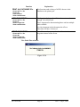
Once you have entered data in all the required fields, click
If you have checked “Alarm Automation System?” you will see the screen
shown on the next page. If you did not, this screen will be skipped.
40-7705I-UM
Page 36
Rev 5 July 9, 2010
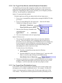
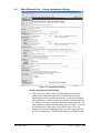
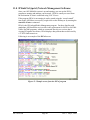
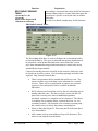
6.3
Add a Business Unit – Alarm Automation Settings.
Figure 6-5 Automation Settings
o Alarm Automation System Settings:
40-7705I-UM
If the Check-In, Alarm, Status, Trouble and Restore messages
produced by a subscriber unit will be monitored by an alarm
automation system or monitoring software, you need to configure
these parameters. Failure to do so may prevent vital messages like
AC failure, Low battery and other faults from being reported. You
must check the “Alarm Automation System?” checkbox. You will
be presented with a data entry screen shown above. You can
connect to the alarm monitoring system via serial connection and
or TCP/IP connections. The following fields are available to edit.
Page 37
Rev 5 July 9, 2010
WARNING! AVOID ERROR MESSAGES
Be sure there is a functioning Alarm Automation system properly
attached and in service on the configured port and or IP address,
ready to receive signals immediately after the parameters are
saved. Messages may be generated and any enabled heartbeat
needs to get its proper responses.
Leave the Serial Device Name, Heartbeat Signal frequencies and
IP Address blank, if you need to configure a security Business Unit
to not produce error messages, due to no in service Alarm
Automation System.
Special Instructions: If this is an additional Business Unit that will use a
Serial Port that has already been assigned and configured, then a Blank
entry MUST be used in the Serial Device Name and Heartbeat Signal
Frequency fields. Instructions in Appendix D must be followed after
completing this Business Unit, to link it to the Business Unit that has a
configured serial port, before it will be able to utilize the Serial Port.
o Serial Port Parameters:
Serial Device Name: Enter the name of the serial device used for
the serial port. Default value is: /dev/ttyS1 for COM1 (upper serial
port). /dev/ttyS0for COM2 is used internally and is not available.
Com Parameters: Select the Baud Rate, Data Bits, Parity, and Stop
Bits to use on the Serial for these alarm automation messages.
Default values are 1200, 7, Odd and 2 Stop Bits. See Appendix E
for a listing of generated messages.
Heartbeat Signal Frequency: Enter the number of seconds between
heartbeat signals on the serial port from Alarm Automation. The
heartbeat is an upper case “S” when in Ademco 685 emulation.
You should add a period of time as a window that the signal may
be sent. Example: If your Alarm Automation sends an “S” every
20 seconds, you may want to set this parameter to 40. This allows
the Alarm Automation an additional widows of 20 seconds and
two attempts to send the heartbeat before a fault message is
generated by the 7705i Receiver. This shall be configured by
UL1981 Central-Station Automation Systems Requirements.
Entering a value of 0 disables the feature and the 7705i will not be
looking for the heartbeat. The MultiNet Receiver will not
annunciate a fault due to no heartbeat being sent.
o IP Parameters:
40-7705I-UM
IP Address: Enter the IP address of the Alarm Automation system.
The default is blank and should only have an entry if there is to be
communication to Alarm Automation via TCP/IP.
Port Number: is the IP port that the 7705i send it alarm automation
messages on. Default is blank.
Page 38
Rev 5 July 9, 2010
Heartbeat: Enter the number of seconds between heartbeat signals
on the IP port from Alarm Automation. The heartbeat is an upper
case “S” when in Ademco 685 emulation. You should add a
period of time as a window that the signal may be sent. Example:
If your Alarm Automation sends an “S” every 20 seconds, you
may want to set this parameter to 40. This allows the Alarm
Automation an additional widows of 20 seconds and two attempts
to send the heartbeat before a fault message is generated by the
7705i Receiver. Default is 0 or disabled. This shall be configured
by UL1981 Central-Station Automation Systems Requirements.
o Automation Message Format:
Automation Format: Select the emulation to use for messages
using these settings. Select either Ademco or Radionics according
to the configuration of the alarm monitoring system. See
Appendix E for a listing of generated messages.
Receiver Number: Select the number to place in the character(s)
that represent the Receiver Number in the Alarm Automation
message. Default is 1. Range is Blank, 0 to 9 and A to F. 0 and
Blank are selectable options but may not be valid entries for all
alarm Automation systems. Some Alarm Automation systems may
ignore or be set to ignore this parameter.
Unless you know you need or want something different, use the
default and suggested value of 1.
o Automation Message Printing:
This parameter controls how the MultiNet receiver prints alarm
messages to its assigned printer.
Options are:
Print only when alarm automation is down. All messages will print
but only those that cannot be reported to alarm automation.
Print alarms sent to automaton. This setting echoes successfully
reported messages to the printer.
Always Print Automation Messages. This setting prints all
messages regardless of state of alarm automation.
o Email Alarms:
Optionally you can enter an email address to send alarm messages.
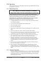
o Old Alarm Delivery:
Old (or prior) alarms are reported by AES Subscribers when a zone
that has gone into alarm in the past and has not yet restored to its
non-alarm condition at the time the Subscriber is sending a CheckIn or a Status report.
UL 864 requires a setting of:
“Deliver all old alarms for this Business Unit.”
40-7705I-UM
Page 39
Rev 5 July 9, 2010
Some Alarm automation systems may not be configured to
properly report these types of messages. You may have some
other reason not to send these to automation but, be aware, these
are important messages as they indicate zones that are possibly
stuck, improperly configured, improperly wired or in an alarm
condition and may not be able to report a new event.
Options are:
Individual Subscriber Unit settings control delivery… , which is
configured for each Subscriber in its configuration settings.
Deliver all old alarms… , which will ignore Subscriber
configuration and report all old alarms to automation.
Never deliver old alarms… , which will ignore Subscriber
configuration and not report all old alarms to automation.
Once you have entered data in all the required fields, click .
If you selected Universal Unit ID Range, the following
screen appears.
Figure 6-6 Add a Business Unit – Universal IPLinks
Enter the ID or IDs of the IP-Link Transceivers that will handle the
Subscribers for this Business Unit.
When complete click…
The following screen, or one similar if Alarm Automation System were
not checked should be presented. After reviewing the information,
Click Add Business Unit to complete the process
40-7705I-UM
Page 40
Rev 5 July 9, 2010
Figure 6-7 Add a Business Unit - continued
A partial view of the final screen indicating a successful add, is shown
below.
Figure 6-8 Add a Business Unit – completed
40-7705I-UM
Page 41
Rev 5 July 9, 2010
6.4
Business Unit Overview
Once you have created at least one Business Unit you can select Overview
to view its information. Below is a sample partial screen that shows
several Business Units. You can select an underlined link, to view details.
Figure 6-9 Business Unit Overview
Below is a sample compressed screen that shows the details for the
underlined link MySecurityOne.
Figure 6-10 Business Unit Details
40-7705I-UM
Page 42
Rev 5 July 9, 2010
6.5
Modify a Business Unit
Select
in Business Unit Details screen to
make any changes. The following combined screens image may appear
different depending on the type of Business Unit.
Leave these
fields blank
if this BU
will be
linked to
another that
is already
configured
to use the
Serial Port
to alarm
automation.
Selecting a
different
receiver
number for
each BU
will produce
a unique
alarm
message for
each. This
affects the
receiver
number in
the string of
characters
sent to alarm
automation.
Figure 6-11 Modify Business Unit:
40-7705I-UM
Page 43
Rev 5 July 9, 2010
6.6
Subscriber Database Setup
Each subscriber unit needs to be configured and assigned to a Business
Unit, Subscriber configuration allows you enter the IDs of your units
individually, or as a range of IDs within the same Business Unit.
Add subscribers by clicking the link on the left hand menu, “Add” under
“Subscribers”.
Figure 6-12 Add Subscriber
You will first be prompted to select the Business Unit to assign the added
Subscriber.
•
40-7705I-UM
Business Unit: Select from the pull down list. A different list
from another example system is shown in this example.
Page 44
Rev 5 July 9, 2010
• After selecting the Business unit, click on
The following fields will be presented.
Figure 6-13 Add Subscriber to Business Unit Screen
•
Subscriber ID: The Add page first asks if you want to
configure a single subscriber or a range of subscribers.
Configuring a range of subscribers can be convenient if you
have a series of subscriber units, consecutively numbered, for
the same Business Unit. Enter the subscriber ID(s) and use the
radio buttons to indicate whether you are configuring a single
subscriber or a range of subscribers.
Subscriber unit IDs can be entered as Hexadecimal or Decimal
numbers. Use the radio buttons below the ID entry fields to set
the number type.
Note: An ID entered in Decimal will be converted to
Hexadecimal for use and database storage. Use caution if you
enter an ID as decimal as once it is translated into Hexadecimal
and stored, you will have to know the Hexadecimal translation
to view data on some screens. Subscriber ID’s are actually
entered in Hexadecimal format when programming the unit
using the programming port. Entering the ID of 1234 into a
unit would be an equivalent of 4660 in decimal or 6666 entered
as decimal will be converted to the Subscriber ID of 1A0A.
When entering a range, decimal and Hex digits will have to be
entered separately. A range of 0001 to 9999 will include all
ID’s with numbers 0-9 but none of the Hex digits A-F. To
include the Hex numbers in the range create a René.
•
40-7705I-UM
Unit Type: Select the unit type from the pull down list
provided. If the unit type is not properly selected, certain
operational functions, such as Zone Programming, may not
work correctly. You may not be presented with the correct
zone-programming window.
Page 45
Rev 5 July 9, 2010
•
Enter optional address information in fields Line 1, Line 2,
City, State, Zip and Country if desired.
Once fields are edited select “Add Subscriber” button, the next screen will
display the data you entered for verification. If displayed data is correct,
click the “Insert Subscriber” button to add the subscriber to the database.
If it is incorrect, use the “Back” button of your browser to return to the
Add Subscriber page to make corrections.
Figure 6-14 Add Subscriber Confirmation - partial Screen
You will receive a confirmation screen after you click the “Insert
Subscriber” button, verifying that the subscriber was added to the
database. From here, select the [Add alarm data] button to configure
alarm data for this subscriber.
Figure 6-15 Add Subscriber Confirmation Screen
When you successfully add a subscriber, you are given the option to add
alarm data after adding the subscriber.
Click
40-7705I-UM
to perform this step next.
Page 46
Rev 5 July 9, 2010
6.7
Alarm Data
There are several modifiable parameters that control data sent to the alarm
monitoring system by ipctrl.
See Appendix E for a listing of generated messages.
You can also modify alarm data at a later time by viewing detailed data for
the subscriber then clicking the
screen.
button on that
The Add Alarm Data page allows you to configure the following alarm
parameters for subscribers as shown in the following view of the Add
Alarm Data page:
Figure 6-16
•
40-7705I-UM
accountAlias: If a non-zero number is entered into this field, the account
number in the alarm event will be replaced by this number prior to
delivery to the automation system.
Page 47
Rev 5 July 9, 2010
When you have modified the fields click
to accept any
changes. The Add Alarm Data screen will ask you to verify the alarm data
before it is added to the database.
Figure 6-17 Add Alarm Data – Insert Alarm Data
When you add a range of subscribers, you can configure identical alarm
parameters for all subscribers in the range. If any subscribers need certain
parameters to be different, you can then use the Modify Alarm page to change
the parameters for individual subscribers.
Figure 6-18 Alarm Data Added
6.8
Close Your Browser When Finished With Admin GUI:
To help secure your MultiNet receivers configuration and help to limit
unauthorized modifications to your system, you should close your browser
when it is no longer needed. For the same reasons, do not leave untended,
a workstation that has the Admin GUI Web pages open.
Closing the browser will require the Admin GUI Password for a
subsequent access attempt.
40-7705I-UM
Page 48
Rev 5 July 9, 2010
7.0 Workstation Access and Login:
Once properly configured, the 7705i can be accessed by using programs running
on a workstation. There are as usual multiple configurations and programs that
will accomplish this task. As you have already experienced, password protected
Web access to the Admin GUI is available as described in Section 6.0. Access
using VNC Viewer should have been configured and be running. This should at
least be true for user root on display number 1 as well as any users created during
the Add Business Unit process.
7.1
Programs for Access Via a Workstation
VNC: is an acronym for Virtual Network Computing software which makes it
possible to view and fully-interact with one computer from another computer.
VNC software is cross-platform, allowing control between different types of
computers.
Following are instructions for using the AES supplied VNC program with access
as root user. Examples show default IP settings and configurations to connect to
your MultiNet receiver using a Microsoft Windows workstation. Replace any
example IP address with those appropriate for the receiver you are accessing.
X-Win32: by StarNet Communications is a third party program that can be
purchased independently and installed on a Windows PC. This program allows
access without needing to run a special server program on the MultiNet receiver.
Check their Web site for latest version and information:
http://www.starnet.com/
40-7705I-UM
Page 49
Rev 5 July 9, 2010
7.2
Installing VNC Viewer:
● From a Windows workstation PC, start a Web
browser and enter the URL of the Admin GUI on a
MultiNet Receiver as described in Section 6.0.
From the main or home page of the Admin GUI there
is a link on the bottom of those available on the left
side of the screen that can be used to download a copy
of the VNC Viewer program.
● Click on the “VNC Viewer” link:
● Click on the “Download VNC Viewer” Link
● Click on Save:
● Save the file in an appropriate
location that you will remember for
the next step. A folder under
Program Files would be an
appropriate location.
● Create a shortcut on your desktop
to the vncviewer.exe file saved in the
previous step. Right click on
desktop and select new .. Shortcut …
You can use the browse button to
look for the file you saved
Double click on the shortcut just created to run VNV Viewer.
40-7705I-UM
Page 50
Rev 5 July 9, 2010
7.3
Using VNC Viewer:
From a Windows workstation PC, start the VNC Viewer by using the shortcut
created in the previous section. The following screen should appear.
Figure 7-1 VNC Connection Details Window
Type into the “VNC server:” box, the IP address and Display number separated
by a colon, of the MultiNet Receiver’s VNC Server Display you are attempting to
access. The Display number is the unique number created for the user. This
Display number is created at the time the Business Unit is created from the Admin
GUI Web pages, and will be unique to the specific Business Unit.
Display “:1” is factory created and reserved for root user access. It is the only
user that can manage other users. To read the Display numbers and passwords
automatically generated and stored in the user_info file during the add Business
Unit process, you must connect using root access on display 1. See Managing
Users in Section 9 for additional information.
Example: 192.168.0.101:1 then click [OK]
If successful the following window should appear:
Figure 7-2 VNC Password Authentication
Enter the current password for selected user and click OK. The AES factory
default password for root using display 1 is peabody2. You should now be
connected and be able to run programs as needed.
An example of the screen you should see is in the next section.
40-7705I-UM
Page 51
Rev 5 July 9, 2010
7.4
After login:
•
You should be presented with the Linux MWM GUI Desktop. You will now
be able to start the authorized programs and perform functions you need to
operate, configure and maintain the system.
An example of the desktop screen as seen using remote access follows:
Figure 7-3 Remotely accessed GUI Desktop
Instructions for using the GUI Desktop can be found in:
Section 5.7 “The GUI Desktop and the AES Menu:”
If you are connecting for a user associated with a Business Unit you will have the
Ipctrl program on the screen. Ipctrl is the interface you will use for managing
Subscribers assigned to you.
40-7705I-UM
Page 52
Rev 5 July 9, 2010
8.0 MultiNet Receiver Programs and Utilities:
There are a number of programs, scripts and special purpose circuits that are
installed in an AES MultiNet Receiver. Some are programs that are installed by
AES to make your Linux Server a MultiNet Receiver. Others are utilities used to
configure and maintain it. There are also a number of others that are part of the
operating system installation. Also included are special purpose circuits for
monitoring the proper operation of the programs and hardware.
Many programs are started during a normal boot up of the system. Utilities are
usually started by request of a user. The following sections explain those that are
useful or specific to the operation of the MultiNet Receiver.
8.1
MultiNet Specific Programs:
Below is a list followed by a brief description of each of the programs that make
up the AES 7705i MultiNet Receiver.
1- ipes
4- aesmon
2- ipctrl
5- LCD
3- deliver
6- filedaemon
1- ipes is the server program that communicates with the IP-Link Transceivers.
It needs to be configured with a Port Number and ServerID. The setup can be
done from the Admin GUI under “Server Configuration. See Figure 6-2.
2- ipctrl is the Radio Management Program. It is similar to the Net7000
program that standalone IntelliNet receivers use. Most of the screen displays
network activity. Network activity scrolls up the screen. In normal
communication monitoring mode, radio data “traffic” whose destination is the
central receiver, and is in range of the IP-Link Transceiver is displayed. This
is a valuable tool for monitoring and controlling the RF network.
3- deliver is the program that manages the distribution or sending of alarm
messages to the automation system. It is configured using the Admin GUI,
shown in Figure 6-2. Deliver can communicate alarm automation messages
via RS-232, TCP/IP or both. See Appendix E for a listing of generated
messages.
4- aesmon is a program that monitors the ipes, ipctrl, deliver, LCD and
filedaemon programs every 5 seconds to test that these programs are up and
running. It restarts any program that is not running.
5- LCD is the program that controls the messages displayed on the LCD display
located on the front panel on the 7705i MultiNet Receiver.
6- filedaemon is the program that handles the data sent to the printer.
Refer to Appendix F for a listing of printed messages.
40-7705I-UM
Page 53
Rev 5 July 9, 2010
8.2
MultiNet Utility Programs and Scripts:
Listed below are some of the more commonly used programs, utilities and script
files provided by AES or your Linux installation to manage, configure and
maintain your MultiNet Receiver
1- Admin GUI
4- cleanLCD
2- aesctrl
5- editnetworketh0
3- chpass
6- editnetworketh1
1- Admin GUI: (Graphical User Interface)
The Admin GUI is essentially a collection of Web pages that an administrator
can use to manage a MultiNet System. You can use a web browser to access
the Admin GUI Web pages. The Web browser can be run on a workstation
with access to the MultiNet Receiver’s network or from the Web browser
included in the MultiNet Receiver’s installed software packages.
•
If accessing the Web pages from a network workstation use the IP
address of the MultiNet receiver as configured in section 5.
Default for Receiver would be:
http://192.168.0.101/Admin/home.php
•
If accessing the Web pages from the MultiNet Receiver’s keyboard
and monitor use the following URL:
http://localhost/Admin/home.php.
The Admin GUI is a php program that allows the operator Admin, to modify
the server’s configuration, Add Business Units (configure the delivery
program if any) and Add Subscriber Units.
See illustrations beginning with Figure 6-2.
2- aesctrl [stopall | startall | status] is a command script that allows the operator
to stop and start the programs from the source. Arguments are added to the
command line to instruct this script how to proceed. aesctrl is typed into the
command line with an argument added as described below:
This command with the startall argument will attempt to start every ipctrl
Business Unit, ipes, aesctrl, deliver, aesmon and filedaemon.
Use the following command to start the MultiNet programs:
aesctrl startall<Enter>
You will need to close the terminal window and open a new one after
executing this command as commands will scroll on the screen regularly.
This command with the stopall argument is used to stop the programs listed
above. Use the following command to start the MultiNet programs:
aesctrl stopall<Enter>
This command with the status argument is used to get the status of the
programs listed above. Use the following command to get the status of the
MultiNet programs and determine if it is running:
aesctrl status<Enter>
40-7705I-UM
Page 54
Rev 5 July 9, 2010
3- chpass is script is used to change the password of a user created by the new
Business Unit function in the Admin GUI Web pages. You will be asked for
the username and new password. Passwords must be exactly 8 characters
made up of case sensitive letters and numbers. New passwords will take
affect after executing this command because the VNC Server session for the
user that the password is changing will be shutdown and restarted within this
script.
4- cleanLCD Clears alarm messages on the LCD display.
5- editnetworketh0 – This script is used to modify the settings of Ethernet Port
1 (eth0). See Section 5.13
7- editnetworketh1 – This script is used to modify the settings of Ethernet Port
2 (eth1). See Section 5.13
40-7705I-UM
Page 55
Rev 5 July 9, 2010
8.3
Special Purpose Circuits:
Listed below are some of the notable special purpose circuits whose purpose is to
monitor certain faults or the proper operation of the MultiNet Receiver.
1- Watchdog Timer / Hung process detection
2- Power Supply Overheating Detection
1- Watchdog Timer / Hung process detection: Many of the critical programs
in the MultiNet Server suite are providing a pulse to a Watchdog circuit on the
LCD Board. The purpose of this pulse is to verify that the programs are
performing their functions in a timely manner and not hung.
To test for the existence of an operational Hard Drive, many of the programs
are accessing the drive at regular intervals. If a program becomes hung for
any reason including its inability to access the drive, the Watchdog Circuit
will not receive the pulse. If the Watchdog circuit does not receive a pulse,
the MultiNet Receiver will annunciate the fault within 90 seconds.
To annunciate this fault condition, which includes a lost or failed hard disk
drive, the following will occur:
•
•
At about 1 minute the LCD will display the message:
“COMM FAILED”
”VERSION ####”
At about 90 seconds:
o The Alert Sounder will activate
o The CPU and Alert LED will illuminate
Pressing the Silence Button should silence the Alert Sounder.
If the Acknowledge Button is pressed, the LEDs will clear but the fault will be
re- annunciated in several seconds. This fault cannot be acknowledged.
Although it is possible that the MultiNet Receiver may continue to process
signals for some period of time, total failure is imminent and corrective action
must be taken. Never continue to operate the MultiNet receiver when the
Alert LED cannot be cleared.
2- Power Supply Overheating Detection: A temperature sensor is incorporated
into the power supply. If it detects a temperature above its normal operational
range, the following will occur”
•
The Alert Sounder will activate
•
The Silence and Acknowledge Buttons will have no affect on the
Sounder.
Although it is possible that the MultiNet Receiver may continue to function
normally and process signals for some period of time, failure is possible and
corrective action must be taken. Never continue to operate the MultiNet
receiver when the Sounder is active and cannon be silenced.
40-7705I-UM
Page 56
Rev 5 July 9, 2010
8.4
AES Menu in the GUI Desktop:
There are no desktop shortcuts on the MultiNet Receiver’s
GUI Desktop. Use the AES Menu to access some of
functions that are available. Other functions are available
from the command line prompt. This menu is only
available for root user access.
See Section 5.7
1- New Terminal – Shortcut to start the xterm terminal
emulator used to get a command line prompt.
2- aesctrl startall – Shortcut to run the startALL shell
script which starts the collection of programs that make
up the MultiNet receiver.
3- aesctrl stoptall – Shortcut to run the stopALL shell
script which stops the collection of programs that make
up the MultiNet receiver.
Figure 6-1
AES menu
4- aesctrl restartall – Shortcut to run the restartALL shell script which stops
then restarts the collection of programs that make up the MultiNet receiver.
5- Clean LCD Alarm – Shortcut to reset the LCD display
6- Primary LCD Clean – Shortcut to reset the LCD display
7- Secondary LCD Clean – Shortcut to reset the LCD display
8- Primary Housekeeping – Shortcut to reset LEDs
9- Secondary Housekeeping – Shortcut to reset LEDs
10- Reboot server! – Shortcut to stop all programs, shut down and restart the
MultiNet receiver.
11- Shutdown Server! – Shortcut to properly stop all programs and shut down
the MultiNet receiver. You should never just remove power from the receiver
or turn off the power supply On/Off switch to turn off the receiver. Damage
to the file system may occur if not properly shut down.
12- Quit… - Use this function to quit using the MWM GUI and return to a
command prompt.
40-7705I-UM
Page 57
Rev 5 July 9, 2010
9.0 Managing Users:
Generally, users are created and managed within the MultiNet system through the
creation of the Business Unit. See section 6.2. Within a server environment a
user would be given specific access rights to areas on a server where they could
do things such as view, create, delete, modify and other actions to files while
limiting access to areas where they do not need to be. This protects the system
and other users.
User “root” and several other users were created on your MultiNet receiver at the
factory. Default passwords were assigned to those users. User root is typically
the most powerful user in a Linux server and has access to do anything on the
server. Other factory created users are AES Engineering and Technical Support
user access accounts that were created to provide factory assistance and support
for your system and the passwords are not published.
You should change the factory default password for user root to protect against
unauthorized access. See “Changing a user’s Password” below.
Remote access to a MultiNet receiver is possible once attached to a network. The
VNC Server program is configured to start automatically on boot up and this will
allow remote access. There are also other readily available programs that can
gain access without special programs running on the receiver. Not changing the
password could easily allow remote access to those that know or discover the
server exists on an available network.
Where users are mostly managed by the creation and deletion of the Business
unit, you will not typically need to create your own users directly. Changing
passwords of a user is one operation that must be done outside the Admin GUI.
See “Changing a user’s Password” below.
9.1
Adding a user:
This is done when you create a Business Unit. The username is the name you
give to the Business Unit during the Add Business Unit process.
9.2
Retrieving user Display Number and Password:
An initial password and a unique Display number are generated automatically
during the Add Business Unit process. The password and Display number for
users created in the Admin GUI are located in the file named “user_info”
located in root directory. Only the root user can read the file. This is the
directory you would be looking at after a successful login as user root. Type
the following command at a command prompt to view this file:
cat user_info<Enter>
After reviewing the information press Q to quit the viewer and return to the
command prompt:
If you are not in the root directory or to be sure you are type the following:
cd /root<Enter>
Or to view the from any other directory type the following command:
cat /root /user_info<Enter>
40-7705I-UM
Page 58
Rev 5 July 9, 2010
9.3
Changing a user’s Password:
AES has provided a script for use in changing the password of a user that
already exists. Only the root user can change passwords using this script.
Warning! This script should also successfully change the password for user
root, but be very careful as the VNC Server for the user is stopped and
restarted during this process effectively disconnecting you if the password
being changed is for the root user and you are connected via VNC Viewer.
Be prepared for your VNC Viewer session to close.
At the command prompt enter the following:
chpass<Enter>
The script will ask for the username:
Enter the user name whose password you wish to change:
{username/Business Unit Name}<Enter>
If the user is found, the script will ask for the new password:
(The password must be exactly 8 characters of case sensitive letters and
numbers)
User OK. Please enter user’s new password:
{new password}<Enter>
You must enter the password a second time. The two will be compared.
Please enter the password again:
{new password}<Enter>
A response by the script will let you know if it was successful or what error
was encountered.
Select a password that is appropriate for the user you are creating. The more
complex it is the more secure your system will be and the less likely that an
attacker will guess it and gain access. Using telephone numbers, birthdays
and the like are not recommended and could be easier to guess leaving your
system at risk. An example is something similar to: “Ax2zT78o”.
40-7705I-UM
Page 59
Rev 5 July 9, 2010
9.4
Change Admin GUI Access - Username and Password:
The username and password used to gain access to the Admin GUI is factory
set as username = Admin; Password = peabody. It is highly recommended
that this password be changed. Not changing it means that anyone who knows
or discovers the server could use the Admin GUI Web pages to modify and
possibly disable your system. The factory default passwords are published.
Follow these steps to change the username and password for Admin GUI
access. You can keep the same name by simply typing that name on the
command line in place of newname.
•
Start VNC Viewer or use local access and log in to the MultiNet
Receiver as root and get to a command prompt.
•
Enter the following command to change to the directory where the
Web Server files are located:
cd /usr/local/apache/bin<Enter>
•
Enter the following command to change the username and password
for access to the Admin GUI login:
./htpasswd -c /usr/local/apache/htdocs/admin.users {newname}<Enter>
9.5
•
You will be prompted for a new password twice.
Enter the new password twice.
•
Enter the following command to stop the apache Web Server.
./apachectl stop<Enter>
•
Enter the following command to start the apache Web Server.
./apachectl startssl<Enter>
•
Once restarted the new username and password should be in effect.
•
Attempt to access the Admin GUI using the new username and
password
Deleting a User:
This is managed by the deletion of the Business Unit within the Admin GUI.
40-7705I-UM
Page 60
Rev 5 July 9, 2010
9.6
Test new user login:
New user access should be tested after creating a Business Unit or changing a
password. Read or confirm the new password and Display number from the
file user_info as described above in Section 9.2. Log in using the new login
information to verify the proper creation/modification of the user.
● If you are working from a remote workstation, you can test as outlined
below:
o Determine the display number and password by looking in the
user_info file.
cat /root/user_info<Enter>
o Open a new VNC Viewer and use the display number and password
determined above.
o If operation appears normal you were successful.
o Close the VNC Viewer.
● If you are working from the directly attached keyboard and monitor, you
can test as outlined below:
o If using the Linux MWM GUI, select “Quit…” from the AES menu.
o Next type exit<Enter> or logout<Enter> from the command line
prompt.
o At the “aes login:” prompt type
{username}<Enter> replacing username with the name of the
Business Unit you are testing.
o Enter the password followed by <Enter> when prompted.
o Once successful, confirmed with a prompt including the username you
typed, you should logout again. Type logout <Enter>
40-7705I-UM
Page 61
Rev 5 July 9, 2010
10.0 Admin GUI Database Functions:
Once your AES MultiNet system is up and running, and has received signals from
Subscribers, you can use the Admin GUI access to monitor Subscriber activity
history. Admin GUI is usually accessed from your remote PC.
10.1 Subscriber Overview
Following is a portion of the screen that is displayed when you select
Subscriber / Overview. To review details about a specific unit select a
Business Unit from the pull down and then click
.
Figure 10-1 Select Business Unit
The next screen will allow you to select a subscriber form the list.
Figure 10-2 Select Subscriber ID
The next screen will provide the options to Modify Subscriber Configuration,
Alarm Data or Delete Subscriber. By now you should have seen most of
those screens.
Figure 10-3 Data for Subscriber
40-7705I-UM
Page 62
Rev 5 July 9, 2010
10.2 Routing Table Screen:
Once you have configured your Business Unit(s) and added Subscribers
you can go to the ipctrl program discussed later in this manual, to view
live traffic and manage your network. Data will be stored in the various
databases as traffic comes in. You can then return to the Admin GUI and
review that data using the following screens.
You can view Routing information by selecting a link located in the
Business Units area of the Admin GUI. Select Business Units / Overview
on the left side of the screen. Then select the Business Unit that contains
the Subscriber you want to review routing history from the pull down list.
Next click on the Link “View Route table for {Business Unit Name}”.
An example screen is shown below. When your system is new there may
not be any information to display until signals are successfully received by
an IP-Link Transceiver and passed on to the 7705i MultiNet Receiver.
Figure 10-4 Routing Table
Note: The information on this screen will vary from what is shown
depending on weather any and what signals may have been received by
this 7705i MultiNet Receiver.
Figure 10-5 Empty Routing Database
40-7705I-UM
Page 63
Rev 5 July 9, 2010
10.3 IP-Link Status Screen:
You can also view the status of IP-Link transceivers as shown in this
partial screen view accessed from SysOp / IPLinks:
Figure 10-6 IP-link Transceiver Status Screen
10.4 Get Signal History:
Alarm data that is stored can also be viewed. The following screen,
accessed by selecting SysOp / Alarms, lets you select the specifics about
the alarm data you wish to view.
Figure 10-7 Get Alarm data, (Signal History) request screen
40-7705I-UM
Page 64
Rev 5 July 9, 2010
Shown in the following Figure is an example of a Signal History Screen for a
Subscriber with an ID of 1010:
Figure 10-8 An example Alarm Data (Signal History) Screen
10.5 Close Your Browser When Finished With Admin GUI:
To help secure your MultiNet receivers configuration and help to limit
unauthorized modifications to your system, you should close your browser
when it is no longer needed. For the same reasons, do not leave untended,
a workstation that has the Admin GUI Web pages open.
Closing the browser will require the Admin GUI Password for a
subsequent access attempt.
40-7705I-UM
Page 65
Rev 5 July 9, 2010
11.0 IPLinkCtrl (ipctrl) Network Management Software:
Once your AES MultiNet system is up and running, you can use the IPCtrl
program to monitor and manage your network. IPCtrl is usually accessed from
the workststion PC that is connected using VNC Viewer.
If the program IPCtrl is not running it can be started using the “aesctrl startall”
item in the AES Menu, accessed by a right click on the Desktop or by entering the
startALL<Enter> command.
IPCtrl is the IP-Link and Radio Management program. For those familiar with
standalone AES IntelliNet receivers this is the replacement for Net7K or Net7000.
Unlike Net7000 programs, which are connected directly to a receiver that is
viewing RF signals in real time, IPCtrl displays data packets that are delivered by
a 7170 IP-Link transceiver.
Following is an example of the IPCtrl screen.
Figure 11-1 Sample screen from the IPCtrl program
40-7705I-UM
Page 66
Rev 5 July 9, 2010
11.1 IPCtrl Function Groups:
There are five function groups including “ Message”, “Control”,
“Program”, “DataRadio” and “System”
They are accessed from the menu bar in the upper part of the screen. Each
of the menu bar function groups has an underlined letter.
Menu function groups can be selected by holding down the <Alt> key
pressing the function group’s underlined letter on your keyboard please
see example on next page: or by clicking on the Menu Item with the
mouse cursor.
11.2 Common data entry/selection menus and pop-ups:
Figure 11-2 Message Pull down Menu
• The first of the pull down functions Send Text Message in the example
above, is highlighted as illustrated when the pull down opens.
• Other functions within the pull downs can be selected using the arrow
keys.
• The highlighted function bar also follows the mouse cursor.
• The highlighted pull-down functions will be executed when the user
presses <Enter> or clicks on the function bar using the mouse.
• Each listed function has an underlined letter in its name. Pressing the
highlighted letter while the pull down is active will execute that function.
• Functions can also be accessed directly by a “hot key”, combination
like”<Alt> + <A>. Hot key combinations are listed in the menu to the
right of the item. Hot keys will only execute the associated function when
the pull downs are closed.
• Activate any other function group by clicking on the function group
name in the Menu bar.
40-7705I-UM
Page 67
Rev 5 July 9, 2010
11.3 Using the pick list pop up to Select a Subscriber ID
When a function is chosen from a function group, a “pick list pop-up”
appears.
You can type in the ID number of the Subscriber unit you wish to contact.
Or use the arrow key to highlight the appropriate ID number and then
press <Enter> to select it.
Figure 11-3 Pick list pop-up
11.4 Selecting a Route for Communication with a Subscriber Unit
Since each subscriber unit in your AES•IntelliNet system acts as a radio
repeater, there may be many routes for messages to travel from its source
to the Linux Server via the IP-Link(s). Each time a message is received
from a unit, the software extracts the subscriber unit ID number of the
origin, and the ID number of repeaters in the message’s route. That route
information is stored in a database and can be used to select an outbound
route whenever an operator sends data to a subscriber unit from the Linux
Server.
Figure 11-4 Select a Path
Once you have selected the subscriber unit number, the basic routing popup appears (shown above). You may communicate with the unit through
its most recent route, through its next most recent route, through its most
frequently used route, or you may manually enter a route.
To choose the most recent route of communication, simply press <Enter>
or check the first box. The “last” route, or most recent route, is the default
setting on this popup. To select the second most recent route, select the
most recent route, and the same for the most frequent route.
40-7705I-UM
Page 68
Rev 5 July 9, 2010
To manually enter a route to the subscriber unit, select the Manual Path
Entry and fill out the manual routing screen as instructed below. Where
the first to go thru is the ID of the IP-Link.
Figure 11-5 Manual Routing Table
Once you have entered your communications route, click OK to send the
message to your subscriber unit using the route entered.
11.5 The Message Function Group:
Figure 11-6 Message Pull Down Menu
To access the Message function menu group, hold down the <Alt> key
and Press <M> or click on Message in the menu bar. The pop-up
illustrated above will appear. Use the arrow keys to highlight a message
function and press <Enter> to select it. Proceed by selecting your target
unit and choosing a route of communication.
40-7705I-UM
Page 69
Rev 5 July 9, 2010
Explanation of the Message Group Functions:
Function
SEND TEXT MESSAGE
• Press <ALT>+<A>
or <ALT>+<M>, then <S>
• Select Target Unit
• Select Route
• Type text message
• Press <ALT>+<S> to send
REQUEST STATUS
• Press <ALT>+<R>
or <ALT>+<M>, then <2>
• Select Target Unit
• Press <ENTER> for route
GET SUBSCRIBER
ROUTE TABLE
• Press <ALT>+<G>
or <ALT>+<M>, then <4>
• Select Target Unit
• Select Route
GET ALL
SUBSCRIBER DATA
• Press <ALT>+<M>, then <5>
or Press <ALT>+<L>
• Select Target Unit
• Select Route
(GET) SUBSCRIBER
TIMING DATA
• Press <ALT>+<M>, then <6>
or Press <ALT>+<I>
• Select Target Unit
• Select Route
(GET) SUBSCRIBER
ZONES DATA
• Press <ALT>+<M>, then <7>
or Press <ALT>+<Z>
• Select Target Unit
• Select Route
40-7705I-UM
Explanation
• Sends text messages to a remote subscriber
unit. To receive the data, the remote unit must
have a 7041 Hand Held Programmer attached or
be equipped with a terminal. The most common
use for this function is to test the
communications link by sending data packets.
• Queries a remote unit for its current status,
requiring a "check-in" report back to the central
station. The resulting return message provides
the current status of the remote unit and sends a
status (check-in) message to the alarm
automation port. (See the manual section on
messages types and interpretations).
• Queries a remote unit for its current routing
table. It prints the routing table for this
subscriber, and displays the routing table from
top (best) to bottom. For each unit on the list,
the following items are displayed:
• ID #
• LINK LAYER # • NETCON
• SIGNAL QUALITY between this unit and
queried unit, listed as Good, Fair or Poor
• Queries a remote unit for ALL of it s currently
programmed parameters. The function
automatically performs all the Get functions,
retrieving Timing, Zones, Model #/Rev and
Mode data for the unit you specify. (See
specifics below).
• Queries a remote unit for its current timing
parameters. The received data updates the
timing parameters database. Timing parameters
are part of the Programming Function Group
described in the following pages.
• Queries a remote unit for its current zone
configurations. The received data updates the
Zone Configuration database. The Zone
Configuration is part of the Programming
Function Group described in the following
pages.
Page 70
Rev 5 July 9, 2010
(GET) SUBSCRIBER
MODEL & REV
• Press <ALT>+<M>, then <8>
or Press <ALT>+<E>
• Select Target Unit
• Select Route
(GET) SUBSCRIBER
MODE DATA
• Press <ALT>+<M>, then <9>
or Press <ALT>+<O>
• Select Target Unit
• Select Route
(GET) SUBSCRIBER
PACKET LIFE SETTINGS
• Press <ALT>+<M>, then <A>
or Press <ALT>+<N>
• Select Target Unit
• Select Route
• Queries a remote unit for its model number
(e.g. 7750F, 7450, 7050E, etc.) and its firmware
revision number. This information is stored in
the database.
• Queries a remote unit for the current "mode"
settings (enable/ disable) for 3 different
parameters:
• IntelliTap Message, default = enabled (works
with 7050-E (Ver 2+), 7750-F, 7450, 7440 only)
• Subscriber Repeater Function, default =
enabled (works with all units except 7440, which
do not repeat)
• Telephone Line Cut Function, default =
disabled (works with 7450, 7440 only)
• Queries a remote unit for its Packet Life
Settings (aka Time-to- Live or TTL). This
function can only be used with Version 2+
subscribers with TTL capability. Other are not
supported. This information is stored in the Net
software database.
See also - Radio Packet Life Parameters,
Programming Menu.
11.6 Control Function Group
Figure 11-7 Control Pull down Menu
To access the Control function menu group, hold down the <Alt> key and Press <C>.
The pop-up illustrated above will appear. Use the arrow keys to highlight a control
function and press <Enter> to select it. Proceed by selecting your target unit and
choosing a route of communication.
40-7705I-UM
Page 71
Rev 5 July 9, 2010
Explanation of the Control Group Functions:
Function
TURN ON TX
• Press <ALT> + <C>
• Press <1>
• Select Target Unit
• Select Route
TURN OFF TX
• Press <ALT> + <C>
• Press <2>
• Select Target Unit
• Select Route
Explanation
• Re-enables transmitting on a remote subscriber unit that
has been turned off (see Turn Off TX, next).
• Disables a remote subscriber unit should the need arise,
such as when an alarm system fails and causes the
transmitter to activate repeatedly. NOTE: The unit is not
literally turned off, but is prevented from transmitting until
it receives the "Turn On" signal (above). Also Note that a
transceiver in the Off Mode will create route failed
message when including in an outbound route.
• A reset will clear this mode and return to TX ON.
WARNING: This function disables the subscriber - use it
only when absolutely necessary.
• This function may be used on UL Burglar Alarm and Fire
Alarm systems only with strict adherence to the
requirements of UL Standard 611, Central Station Burglar
Alarm Units and the National Fire Alarm Code, NFPA 72.
REMOTE RESET
• Press <ALT> + <C>
• Press <3>
• Select Target Unit
• Select Route
INTELLITAP
MESSAGES
• Press <ALT> + <C>
• Press <4>
• Select Target Unit
• Select Route
• Enter D to Disable, E to Enable Tap
Messages
• Resets the remote subscriber unit - the same as physically
pushing the reset button on the unit itself. This causes the
subscriber unit to re-enroll on the network and build a new
routing table. A reset may be used to restart the check-in
interval timer. The new interval will commence at the time
of reset (see also: subscriber unit manuals).
• Enables / Disables the subscriber unit's ability to send
IntelliTap Messages. CAUTION: Once disabled, the
subscriber will ignore IntelliTap or FDX data presented to
its port.
• This function works with 7750-F, 7050-E (Ver 2+), 7450
and 7440 models.
• To confirm the function, perform a "Get Subscriber Mode
Data" to retrieve the current status of this mode (Message
group, # 9) and to update the database.
• Refer to subscriber unit and IntelliTap manuals for more
information.
40-7705I-UM
Page 72
Rev 5 July 9, 2010
SUBSCRIBER
REPEATER FUNCTION
• Enables / Disables the subscriber units ability to be a
repeater.
• Press <ALT> + <C>
• Press <5>
• Select Target Unit
• Select Route
• Enter D to Disable, E to
Enable Repeating
• Works with Version 2 or higher subscriber units.
CAUTION: Disabling the repeater capability may cause
problems with the network. Disable repeating for testing
purposes only, or for mobile units, which are never to be
used as repeaters.
• To confirm the function and update the database, perform
a "Get Subscriber Mode Data" to retrieve the current status
of this mode (Message group, # 9)
• Refer to subscriber unit manuals for more information.
TELEPHONE LINE
CUT FUNCTION
• Enables / Disables the Phone Line Cut Monitoring
function in 7450 or 7440 subscriber units.
• Press <ALT> + <C>
• Press <6>
• Select Target Unit
• Select Route
• Enter D to Disable, E to
Enable Line Cut Monitoring
• To confirm the function and update the database, perform
a "Get Subscriber Mode Data" to retrieve the current status
of this mode (Message group, # 9)
40-7705I-UM
• Refer to 7450 or 7440 subscriber unit manuals for more
information.
Page 73
Rev 5 July 9, 2010
11.7 Programming Function Group:
Figure 11-12 Program Pull Down Menu
To access the Programming function menu group, hold down the <Alt>
key and Press <P>. The pop-up illustrated above will appear. Use the
arrow keys to highlight a function and press the <Enter> to select it.
Proceed by selecting your target unit, choosing a route of communication
and then editing the presented form.
Explanation of the Program Group Functions:
Function
SUBSCRIBER TIMING
• Press <ALT> + <P>
• Press <S>
• Select Target Unit
• Select Route
• Edit form as necessary
Explanation
Enter Address
Check-In interval 0..24 Hrs:
Secondary Alarm Delay:
Contact Debounce Time:
Acknowledge Delay:
See below for details on data entry for this function:
Subscriber Programming – Data Entry Screen:
Figure 11-13 Timing Parameters Data Entry
The form illustrated above allows an operator to change the timing
parameters of a Subscriber unit using the IPCtrl software. When the
programming window appears, the fields will usually be pre-filled with
values. If there is a database entry for the selected Subscriber, the values
40-7705I-UM
Page 74
Rev 5 July 9, 2010
will be retrieved from there. If no database entry exists, the factory
defaults will be used.
To be sure that the pre-filled values represent the current settings in
the Subscriber, it is recommended that you retrieve the current
parameters from the Subscriber before you edit and send new values.
See “Get All Subscriber Data” under the Message Function Group earlier
in section 11.
• Enter Address: Freeform field to put location reference
information. This is stored in the database and is not sent to the
Subscriber.
• Set Check-In Interval (Automatic Test): When the Subscriber
Programming screen appears, a cursor will be flashing at the
check-in interval area. The intervals can be programmed between
one minute and 24 hours (the default setting is at 24 hours). To
minimize radio air traffic, an interval of 24 hours is recommended
except in high security applications. The ability to change this
timing feature by remote is a key advantage of the two-way
AES•IntelliNet system. When you have entered a check-in time
interval, press <Tab> to move on to the next field. When done,
click [OK] press to send parameters to Subscriber and update the
database.
• Secondary Alarm Delay (Additional Event Report Delay): This
feature allows a subscriber unit to accumulate alarms, after its
initial alarm report, for a programmed time period. When an alarm
has occurred at a remote subscriber site, the central receiver is
notified immediately. The event report delay allows a remote unit
to compile subsequent alarms for a period of time, so that a
comprehensive packet of alarm data is sent to the IntelliNet system
all at once, thereby reducing network airtime. This delay also
prevents a subscriber from attempting to monopolize the airtime by
having it wait between transmissions. The default setting for this
feature is 10 seconds. To change the event report delay, enter the
new value and press <Tab> to move to the next field.
A delay of less than 10 seconds is not recommended.
40-7705I-UM
Page 75
Rev 5 July 9, 2010
• Contact Debounce Time
(Loop Response) 7050 & 7750/UL only: Programs a debounce
delay for the zone inputs of 7050 and 7750/UL subscriber units to
prevent input switches or relays from causing nuisance alarms and
repeated reports of the same alarm. The default setting is 0.12
seconds. If you choose to change this setting, simply enter the new
value and press <Enter> to move to the next field. A control unit
(panel) output(s) to the 7750 RF subscriber unit shall be
programmed to latch in when it triggers a zone input on the
7750.
Note: The contact debounce time in the 7050-E, 7440, 7450, 7750F4x4 and 7750-F8 units are preset at 0.12 seconds and cannot be
changed.
• Acknowledgment Delay: If a subscriber unit does not receive
an acknowledgment (Packet Acknowledge) within the time
parameters set by the Acknowledgment Delay parameter, it
activates an output to annunciate the problem locally. The next
successful communication to the central station will include an
ACK Delay fault code. The default setting for this feature is 90
seconds. If you choose to change the ACKknowledgment DELAY
period, simply type in the new value. Click [OK] to complete and
send your timing parameter data.
For 7750/UL, 7750-F4x4 and 7750-F8 Subscriber Units: A
zone of the control panel shall be connected to the relay labeled
"ACK DELAY", to monitor the subscriber unit against antenna
removal, communication failure and to provide a local and remote
annunciation of such a fault condition. (Refer to subscriber
manuals.)
NOTE: For all remote program functions, watch to make sure that
a data confirmation packet is received from the target subscriber
(watch scrolling message screen area).
40-7705I-UM
Page 76
Rev 5 July 9, 2010
Function
Explanation
RADIO PACKET LIFE
• Press <ALT> + <P>
• Press <R>
• Select Target Unit
• Select Route
• Edit form as necessary
See below for details on data entry for this function:
Radio Packet Life – Data Entry Screen:
Figure 11-14
Radio Packet Life
Version 2.1 subscribers include the “Time-To-Live” (TTL) function. Like
the Internet, AES•IntelliNet uses a packet-based technology. The Timeto-Live concept in the Internet is based on the fact that all data has a useful
life.
The benefits of TTL are best exhibited when the IP-Link goes off line due
to a lightning hit or some other unlikely, catastrophic event. While the IPLink is off line, messages traveling through the system are stored in the
individual subscriber units for later delivery. Under the default TTL
settings unimportant test timer message (typically 95+% of the traffic) are
deleted from the subscriber unit memory after 30 minutes of being delayed
in the network. Thus, the system will not have to handle the message
when the IP-Link Receiver comes back on line. All other messages, such
as alarm, etc. speed their way to the IP-Link as they normally do.
UL864 requires a setting of 0 for Alarm, Trouble and Restoral.
• Note that even when a check-in packet is deleted due to a delay,
the objective of that message has already served its purpose: the
late or missing signal should have been flagged at the central
station (see Automatic Test Supervision section).
• Under the default (factory) settings, only test timer messages are
subject to the TTL function. If you want TTL for other message
types, YOU must activate it when you program the subscriber unit.
• The TTL time is included in packets generated by TTL capable
Subscribers. This feature is available in Subscribers with firmware
Version 2.1 and later which was first released in late 2000.
40-7705I-UM
Page 77
Rev 5 July 9, 2010
• The timeout function works when a packet is stored for
forwarding in any subscriber with TTL capability, which will
decrement the TTL time for the packet it is storing. When TTL
time has expired, the packet is aborted. This function does not
work with non-TTL (pre-Version 2.1) subscribers. The TTL
feature works best when the majority of subscribers, or the
subscribers that are most heavily used, have the feature in the
firmware. Call your AES representative for upgrade information.
Default time for Check-In Packets is 00 hours, 30 minutes. DO
NOT enter a greater than 24 hrs 00 mins. Entering a time of 00
hours and 00 minutes deactivates the time-to-live function for that
packet type. The shortest allowed TTL time is 00 hours, 10
minutes. TTL can also be set for other packet types:
• Zone Alarm Packets
• Status Packets
• Zone Restoral Packets
• AES-IntelliTap Packets
• Trouble / Trouble-Restoral Packets
The default time for the 6 packet types above is 00, i.e. the time-tolive function is deactivated for these packets. Entering anything
greater than 00 HRS and 10 MINS will enable the Time-to-Live
function. Enter the data for each type, click [OK] to send.
To confirm the data, press <Alt>+<N> to query the subscriber for
Packet Life settings. When the TTL parameters packet has been
received back, check this screen again.
See - Get Packet Life Settings, Message Functions Group
40-7705I-UM
Page 78
Rev 5 July 9, 2010
Function
Explanation
CONTROL RELAY OUTPUT
• Press <ALT> + <P>
• Press <C>
• Select Target Unit
• Select Route
• Edit form as necessary
See below for details on data entry for this function:
Control Relay Output – Data Entry Screen:
This feature controls optional relay outputs (part number 7065) for model
7050 Subscribers units. Using this remote control capability, an operator
may open gates, activate cameras or control any devices at a remote
location. The basic relay output uses eight relays, but as many as 64 may
be controlled.
Relay Programming Window
Figure 11-15 Relay Control Menu
Choose a number: 0 for Off, 1 for On or 2 for Toggle / Momentary and
select [OK] to control Relays in a Subscriber equipped with appropriate
module.
40-7705I-UM
Page 79
Rev 5 July 9, 2010
Function
Explanation
ZONE CONFIGURATION
• Press <ALT> + <P>
• Press <Z>
• Select Target Unit
• Select Route
• Edit form as necessary
See below for details on data entry for this function:
This function configures alarm zone inputs for a premise unit. It is
important to know which type of unit is being programmed. There are
separate sub-menus to handle the different subscriber units. The submenu that will be presented upon selection of a subscriber ID is based on
the database entries. The subscriber model may be selected during setup
in the Admin GUI and using the Get All function in the message group
will update all fields required to identify the unit.
Subscriber models include:
7050/7750-UL (Version 1.8 or older)
7050-E (Version 1.8 or older)
7050-E / F8 (Version 2.0 and newer)
7750
7750F 4X4
To access the Programming function menu group, hold down the <Alt>
key and Press <P>. The Programming window illustrated below will
appear. Select zone Configuration then [OK]. Proceed by selecting your
target unit and choosing a route of communication.
Sample Zone Configuration windows for the various Subscribers are
shown below.
Fire/Inverted Fire programming notes:
If the Subscriber type selected supports Fire and Inverted Fire
programming, these notes apply to the programming sequence and the
following questions will appear before the zone programming selection
window.
Figure 11-16
The programming sequence first asks if any zones are to be programmed
to respond similar to a "Fire circuit". This is not to be confused with the
device usage, but rather how changes to the EOL will be reported. Click
yes if you wish to have the zone report "Trouble" conditions on an open
circuit and alarm on a short. Otherwise click No for alarm message to be
reported on a short or open. A raised appearing button indicates the
default or current programming, if it is stored in the database from a
40-7705I-UM
Page 80
Rev 5 July 9, 2010
previous programming or retrieval.
Next you are asked if any zones are to be programmed to respond similar
to an "Inverted Fire circuit" or bugler loop. With this option you can
select to reverse the logic for the fire input (refer to subscriber manual).
This produces an alarm on an open and trouble on a short. If stored in the
database, the current programming is displayed.
IMPORTANT NOTES:
• The zone programming options are limited. Of the 3 EOL zone
types - Supervised, Fire and Inverted Fire, you can choose any 2.
• You can always choose Bypass and Restoral for any zone.
• Normally open and Normally Close are always available if they
are an authorized option.
Next appears the zone configuration box, which displays the available
options:
Zone Configuration window for the 7050 DLR/7750 UL Bank 0
Figure 11-17
The zone configuration control block for zone 1-8 in Bank 0 offers five
options for the programming of each alarm zone. Bank 0 is the 8 zones on
the main board. Other banks are available if expansion module(s) are
installed. Bank 0 does not support Supervised/EOL wiring or
programming. Bank 2-8 shown next.
Normally Open
Normally closed
Bypassed
Normally Open with Restoral
Normally Closed with Restoral
Use the mouse to select the appropriate boxes for the zone you wish to
program. The numbers below the restoral row selects the bank. Scroll
through the numbers using the arrows and then click the number to select
that bank. The information in the window will change representing those
zones.
40-7705I-UM
Page 81
Rev 5 July 9, 2010
Zone Configuration window for the 7050 DLR/7750 UL Bank 1 - 8
This option row not
shown or available if
Bank 1 is selected
Select Bank Here
Use arrows to
scroll then click
bank number to
select.
Figure 11-18
The zone configuration control block offers seven options for the
programming of each alarm zone:
Normally Open
Normally Open with Restoral
Normally closed
Normally Closed with Restoral
Bypassed
Supervised (Not available on Bank 0, Zone 1-8)
Supervised with Restoral. (Not available on Bank 0, Zone 1-8)
Use the mouse to select the appropriate boxes for the zone you wish to
program. Banks 1-8 support Supervised programming and wiring.
UL and COMMERCIAL FIRE INSTALLATION REQUIREMENTS for
7750/UL Subscriber Units:
•
•
•
Zones 1-6: Bypassed
Zone 7:
N.O. w/Restoral–Tamper (creates N.C. loop through zone 7 of 7072 module)
Zone 8:
N.O. W/Restoral – AC Fail (from 7072 multi-board)
Refer to Subscriber Unit Manual for details on zone wiring and
programming.
Zone Configuration window for the 7050E Rev 1.8 and older
Figure 11-19
40-7705I-UM
Page 82
Rev 5 July 9, 2010
Zone Configuration window for the 7050E, 7750/F8 and 7788
Figure 11-20
In this Subscriber type, the user has the ability to select an optional Contact ID Event
Code to be sent to the Alarm Monitoring System for each of the 8 zones. The former
standard produced only an E140, which is typically listed as a General Alarm.
Select normal to have an E140 sent to alarm monitoring.
Zone Configuration window for the 7450/7440
Figure 11-21
40-7705I-UM
Page 83
Rev 5 July 9, 2010
Zone programming window for the 7750-F4x4 and 7744
Refer to the appropriate Subscriber Manual for details on zone writing
and programming.
This screen below appears if the unit zone information is in the database.
Figure 11-22
The Zone configuration pop-up window offers the following options for
the programming of each alarm zone.
Supervised
Restoral with Supervised or Fire
40-7705I-UM
Page 84
Fire
Bypassed
Rev 5 July 9, 2010
Function
AUTOMATIC TEST
SUPERVISION
• Press <ALT> + <P>
• Press <A>
• Select Target Unit
• Edit form as necessary
Explanation
See below for details on data entry for this function:
Automatic Test Time Supervision – Data Entry Screen:
This feature enables the IPCtrl software to monitor automatic test timer
check-ins. When enabled, it alerts an operator if a subscriber unit fails to
report in within the programmed interval, plus 10% + 2 minutes as
programmed in the subscriber’s timing Parameters function.
A missed Check-In is reported to alarm automation if enabled.
See Appendix E for generated messages.
Access this function from the Program pull down menu. Select the
Automatic Test Supervision or Press <Alt> +<P>, then A. Select the Unit
to be supervised and the following window appears.
Figure 11-23
Automatic Test
Supervision
Select On or Off radio button to configure this function.
Note: Enabling supervision function suppresses Check-In
messages from being sent to automation. Only exceptions are
reported.
40-7705I-UM
Page 85
Rev 5 July 9, 2010
11.8 Data Radio Function Group:
Figure 11-24
To access the DataRadio function group, hold down the <Alt> key and
press <D>. The Pop-up screen illustrated at above will appear. Select a
function. Proceed by selecting your target unit.
Explanation of the DataRadio Group Functions:
Function
Explanation
VIEW ROUTING & STATUS
RECORDS
This function views on the screen the Routing & Status
Records of the selected ID.
• Press <ALT> + <P>
• Press <V>
• Select Target Unit
See below for an example:
PRINT ROUTING & STATUS
RECORDS
This function prints on the printer, the Routing & Status
Records of the selected ID.
• Press <ALT> + <P>
• Press <P>
• Select Target Unit
Information is similar to example below:
An illustration similar to below will appear for view. Similar information
is sent to the printer if Print is selected.
Figure 11-25
It Displays the routing record and current status of the selected Subscriber
unit.
All UL Burglar Alarm and Commercial Fire Alarm Systems require a
minimum of 2 paths.
40-7705I-UM
Page 86
Rev 5 July 9, 2010
Function
PRINT ALL DATABASE ID’s
• Press <ALT> + <P>
• Press <P>
• Click function
• View available data
VIEW PATHS/THRU
• Press <ALT> + <P>
• Press <I>
• Select Target Unit
• View available data
Explanation
This function sends a listing of all ID’s that are in the
Database to the printer port.
This function displays a list of Units that are “routed
through” the selected unit.
This is important for demonstrating that a unit has multiple
paths available.
It is also important to help determine the effect a
Subscriber will have if removed.
PRINT PATHS/THRU
• Press <ALT> + <P>
• Press <R>
• Select Target Unit
• View available data
Same View as above except that the information is sent to
the printer instead of the screen.
View Paths/Thru window:
Figure 11-26
40-7705I-UM
Page 87
Rev 5 July 9, 2010
Function
EDIT RADIO FORWARD
TABLE
• Press <ALT> + <P>
• Press <E>
Select / Enter Origin Unit ID
• Edit form as necessary
Explanation
Forwarding is a function that causes the IPCtrl software to
transmit a data packet to a remote Subscriber upon the
reception of a specific event by the same or another
Subscriber.
See below for details on data entry for this function:
Edit Radio Forward Table:
Figure 11-27
The Forwarding table above is used to configure the event and subscriber
to forward the data to. The types of outbound data packets include data to
be printed on a serial printer attached to the remote subscriber’s serial
port, alarm automation messages and instructions to control relays on an
attached Relay Output module.
Caution! Forwarding increases air traffic on the network, which may lead
to slowdowns on a busy system. Use forwarding sparingly and only when
required. Only forward essential data.
40-7705I-UM
•
There is no guarantee the for-warded data will be received. The
remote site that receives the data is not a substitute for a central
receiver. There will be no notification or report to any external
system if a forwarded packet fails to reach the destination
Subscriber.
•
IPCtrl software can forward the activity data of a subscriber unit to
another subscriber unit. The data received is sent to the RS-232
port of the receiving unit, where a handheld programmer
(terminal), a printer or a computer may be connected. This allows
a secondary site to monitor alarms, restorals check-ins, etc. at a
secondary location. This function is for secondary reporting only the central receiver is always the primary monitoring site.
•
Select or Enter the Origin ID. Then enter the ID of the unit data is
to be forwarded to.
•
Add a memo (such as name/address) of up to 40 characters. This
memo is sent with all forwarded data.
Page 88
Rev 5 July 9, 2010
•
•
•
Select ALARM and/or ZREST plus desired Zones if Forwarding
Alarm data is the objective.
Select as desired any other type of data or feature that you want
forwarded. The following options are available: In some cases the
only information forwarded is a message indicating that a packet of
the selected type was sent and not the data itself,
STAT → Subscriber Status
CHKIN → Check-In
DATA
HPBU → Programming Uploads
TEST Data
ZDATA → Zone Data
VLS → Vehicle Location Data
TEXT → Text Message
Other Options: The following additional features can be activated
for forwarding. These require specific units and capabilities at the
Forwarded to site to be accepted and properly handled.
o Alarm Automation Message: Alarm activity can be
transmitted to the remote unit in Alarm Automation Format.
The RS-232 output of a special "FA" or "FAA" 7050-DLR
receiving unit can feed alarm data directly to a computer
running automation software. Sending these specially
formatted packets to a subscriber that is not intended to receive
it will cause the packet to be rejected.
o Relay Following: This special function requires the ForwardTo unit to be a 7050-DLR subscriber unit with a 7065 Relay
Output board installed. When programmed for forwarding
with relay following and a zone in alarm message is received
from the origin unit, a relay control command is sent to the
receiving unit to activate a relay. Zone 1 in the origin unit trips
relay 1 in the forward-to unit, zone 2 trips relay 2, and so on.
- For 7050 version 2 and later, the relay is momentarily
activated for 1 second. Be aware that the relay may activate
more than one time but should always return to a Normally
Open State
- r 7050 version prior to 2 the relay is toggled. Be aware that
you cannot be sure if the relay will be left open or closed.
Only that it will change state at least once.
40-7705I-UM
Page 89
Rev 5 July 9, 2010
11.9 System Function Group
Figure 11-28
The Systems Function group menu is accessed by holding <Alt> and
pressing <Y>. This group contains functions related to the operation on
the software.
Explanation of the System Group Functions:
Function
Explanation
Abort Outbound Packet
• Quickly cancels an unacknowledged packet sent to a subscriber unit by the receiver. This includes "Get" query
functions.
Filter Check-In & ACKS
• To filter out screen "clutter", this function prevents noncritical check-in messages from appearing on the screen.
This is a "toggle" function.
Forwarding Toggle
• This one command allows you to globally enable or
disable the forwarding function. It affects only those units
that have been programmed for forwarding.
(For more information, see the section on Database Group /
Edit Radio Forward Table.) A pop up window shows you
the current status global forwarding (On or Off). Enter
Y/yes or N/no to change the status.
40-7705I-UM
Page 90
Rev 5 July 9, 2010
11.10 Interpreting Screen Messages
SAMPLE Check-In Message:
The following information can be extracted from the sample message above:
The message was received on September 15th at 12:57:01
The sequential packet number assigned to this packet is 6B
The message originated at subscriber unit #9876, and its destination is Unit #0000 (the head end)
Subscriber #1234 – a “repeater” in the message path, is sending the specific message
This specific message is being sent to Unit #0000 (the designation for the central station receiver)
This is a Unit Check-In / Automatic Test Timer message. It indicates that all is well
The type of routing used:
(LNRT) - Layered Net Routing with Trace, which means automatic routing with trace.
Trace means the path of the packet is being tracked from origin to destination.
This information will be stored in the database
(LNR) - Layered Net Routing without Trace
(EXR) - an operator specified or the software selected explicit routing.
“Data” refers to the data attached or included with this communication. The number after the
word Data indicates the length in Bytes of data included. After the length the data may or
may not be displayed and can be in easily readable or in a raw or Hex computer format if
shown al all. In this case, the 15 bytes of data indicate that the unit is OK.
The ID of the unit transmitting this packet is listed before the “->”
The ID of the unit this packet it is being transmitted to is listed after the “->”.
SAMPLE Alarm Message:
The following information can be extracted from the sample message above:
The message was received on September 15th at 13:19:01
The sequential packet number assigned to this packet is 7C
The message originated at subscriber unit #5678, and its destination is Unit #0000 (the head end)
Subscriber #1234 – a “repeater” in the message path, is sending the specific message to #0000.
The type of routing used is LNRT
This is an Alarm message. It is displayed in red for easy recognition
The 7 bytes of data indicate new alarm on the Subscriber’s Zone 1
40-7705I-UM
Page 91
Rev 5 July 9, 2010
12.0 Operation
This section describes two of the modes of operation your MultiNet Receiver may
be in and how to operate it.
12.1 Manual Operation
The MultiNet receiver defaults to Manual
Operation when Alarm Automation is not in use
Manual operation of the MultiNet receiver is a mode where alarm and other
messages are not being sent to an Alarm Monitoring System. This would occur
when the Alarm Monitoring System was offline, down or disconnected.
Steps for Receiver operation when a MultiNet Receiver receives an alarm
message that is not being sent to an alarm automation system:
1. A waiting MultiNet Receiver receives a message from an IP-Link or detects
an off normal condition.
2. A record of the event is printed on the attached printer.
3. The Alert Sounder activates.
4. The Alert LED illuminates.
5. The message is added to the LCD queue and displayed, if it is at the top of the
queue.
6. The user may press the “Silence” button to stop the Alert Sounder.
7. The user must interpret and properly respond to the message displayed. Refer
to Appendix E for guidance with interpreting the displayed messages.
8. Once the information on the display is no longer needed, the user can press
the “Acknowledge” button to remove the message from the queue.
9. When the Acknowledge is accepted an acknowledge message is printed
indicating which of the previously printed messages is being acknowledged.
A tracking number is recorded to assist in locating it in the logs for future
review.
10. If the message is not acknowledged within 30 seconds of a Silence Button
press, the Alert Sounder is re-activated.
11. Once a message is acknowledged and removed from the queue, the next
message in the queue is annunciated and displayed as described above. If no
messages are in the queue, the MultiNet Receiver returns to its normal waiting
mode.
12.2 Automatic Operation
Automatic operation of the MultiNet receiver is a mode where alarm and other
messages are being sent to an Alarm Monitoring System. No user interaction
is required at the Receiver as long as the Alarm Monitoring System properly
acknowledges the messages.
40-7705I-UM
Page 92
Rev 5 July 9, 2010
13.0 Warranty and Service Procedure:
AES CORPORATION
LIMITED PRODUCT WARRANTY AND TECHNOLOGY LICENSE
LIMITED PRODUCT WARRANTY:
AES Corporation (“AES”) warrants to the original purchaser that each AES Subscriber Product will be free from
defects in material and workmanship for three (3) years from date of purchase and all other products purchased from
AES including central station receivers and accessories will be warranted for one (1) year from the date of purchase.
At no cost to the original purchaser for parts or labor, AES will repair or replace any AES Product or any, part or parts
thereof which are judged defective under the terms of this Warranty.
Defective AES Products must be returned to AES directly, provided they are properly packed, postage prepaid. Or
exchange may be made through any authorized direct factory representative for any AES Products that are judged
defective under the terms of this Warranty. Improper or incorrectly performed maintenance or repair voids this
Warranty. This Warranty does not cover replacement parts that are not approved by AES. This Warranty does not
apply to any AES Product or any part thereof that has been altered in any way to affect its stability or reliability, or that
has been subjected to abuse, misuse, negligence, accident or act of God, or that has had the serial number effaced or
removed.
Certain AES Products are designed to operate and communicate with other specified AES Products and certain other
specified products, systems or networks authorized or approved by AES, as identified in the applicable AES Product
instructions. This Warranty does not apply to any AES Product that is used with any unauthorized or unapproved
products, systems or networks, or that has been installed, applied or used in any manner, other than in strict accordance
with AES instructions.
AES makes no warranty, express or implied, other than what is expressly stated in this Warranty. If the law of your
state provides that an implied warranty of merchantability, or an implied warranty of fitness for particular purpose, or
any other implied warranty, applies to AES, then any such implied warranty is limited to the duration of this Warranty.
AES cannot be aware of and is not responsible for the differing values of any property to be protected by its alarm
reporting systems. This Warranty does not cover and AES shall not be liable for any defect, incidental or
consequential, loss or damage arising out of the failure of any AES Product to operate.
Some states do not allow the exclusion or limitation of the durations of implied warranties or the limitation on
incidental or consequential damages, so the above limitations or exclusions may not apply to you.
This Warranty gives you specific legal rights and you may also have other rights that vary from state to state.
TECHNOLOGY LICENSE:
Certain AES Products include software, protocols and other proprietary and confidential technology and trade secrets
of AES, which are incorporated in or provided, with AES Products solely for use in conjunction with and in order to
operate AES Products (“Licensed Technology”). AES grants the original purchaser a non-exclusive license to use
such Licensed Technology solely in connection with the use and operation of AES Products and for no other purpose
or use whatsoever. No title or ownership in or to any such Licensed Technology is conveyed by the sale or delivery of
any AES Products; all such rights are retained by AES.
AES SERVICE PROCEDURE: Contact AES at (978) 535-7310, [fax (978) 535-7313] to receive a Return
Authorization Number. Have the AES part number and serial number ready. Repack equipment in original or
equivalent packaging. Inside the box, please include a contact name, telephone number, address and a brief description
of the reason for return.
Ship authorized RA items freight-prepaid to:
(call for Return Authorization number)
Repair Services, RA#________________
AES Corporation
285 Newbury Street
Peabody, MA 01960 USA
40-7705I-UM
Page 93
Rev 5 July 9, 2010
APPENDICES
40-7705I-UM
Page 94
Rev 5 July 9, 2010
Appendix A
Common Linux Commands
Below are some of the more common commands you will be using on the Linux
operating system:
cat: concatenate files and print on standard output. Ex: cat {filename}<Enter>
cd: change directory
clear: clear the screen.
cp: copy files
grep: find lines matching a certain pattern. Ex: grep {string} {filename}<Enter>
ifconfig: displays current TCP/IP settings.
less: filter for viewing files and directories. Ex: less {filename}<Enter>
locate: locates files that matches a certain pattern. Ex: locate {filename}<Enter>
ls: list: directory contents
mcopy: copy files to a disk DOS. Ex: mcopy {filename} {destination ie a:}<Enter>
mdir: list directory contents on a DOS contents.
mkdir: make a new directory
passwd: change a user password.
ping: used to test IP connection to another node on the network.
ps: dispaly a process status.
Below are some advanced commands not commonly used or needed but could be useful
for advanced users. Use caution with some of these as incorrect usage could cause a file
or system to be modified and stop normal operation.
etc: system configuration file.
date: used to set the time and date of the server. It is very important that time between multiple
MultiNet Receivers be synchronized. Type man date<Enter> for usage information.
find: find files.
halt: shut down system
host: look up host information.
hostname: display system’s hostname.
mv: move or rename files.
reboot: to reboot the computer.
root: the user that owns the operating system and control the computer
setup: A “Text Mode Setup Utility” that can be used to configure the system including time zone,
network settings, keyboard, mouse, printer to name a few.
shutdown -h now: to stop or halt the computer now.
shutdown -r now: to reboot the computer now.
which: display a program’s executable path
whereis: locate binary, sources and manual pages for a command.
who: show the users who are logged in
whoami: show the users who you are currently logged in as.
tzselect: To set the time zone where the MultiNet receiver is located.
40-7705I-UM
Page 95
Rev 5 July 9, 2010
Appendix B
Server-generated LCD Display Messages.
Top line description:
The LCD is a 4-line display with 20 characters per line. It shows messages for the 7705i.
Use this in conjunction with the Alert panel to interpret and acknowledge messages.
There is also a tactile response sounder to provide audible confirmation of successful
button activation.
In most modes of operation, the top line will be constant and usually displays the LCD
firmware version number and AES copyright.
#.## (C)2005-06 AES
Example: Top line.
Bottom 3 lines description:
The remaining 3 lines will display messages generated
by the server as outlined below.
Default Message: When no alarm, restoral, status or
failure messages are being displayed, and automation is
on line, a default message will be displayed on the LCD
that includes the version of the LCD Firmware, and the
date and time.
#.## (C)2005-06 AES
LCD #.##
07/07/06 12:19
Default Example:
Alarm, Restore and Status messages: All alarm, restore and status messages that are to
be sent by the server to alarm automation, will be sent to the LCD when the alarm
automation system is off line. Following is what occurs when a message of this type
needs to be displayed.
1. The message sent to the LCD will include the message to be sent to alarm
automation, plus a simple human readable interpretation of the alarm that will
include zone, group, etc. The LCD message will also include a timestamp and a
count of pending alarms in the queue. See Appendix E for messages.
2. The Alert LED in the Alert Panel will be turned on if it is off. This will cause the
Alert Buzzer to sound.
3. The Alert Buzzer is tied to the turning on/off of the Alert LED. It will sound
upon the Alert LED being turned on or off. It will sound until the SILENCE
button is pressed.
4. If the alarm is not acknowledged within 30 seconds after a silence, the buzzer
sounds again.
5. Once acknowledged, the message will be removed from the display and replaced
with the next message in the queue. If the next message is not an alarm, the alert
LED will be turned off. Display will return to normal if no off-normal messages
are to be displayed.
6. The database will be updated to indicate a manual acknowledgment for the alarm.
7. The alarm and the acknowledgment will be printed.
8. As the next message is displayed, a short tactile beep sounds as feedback that the
ACKNOWLEDGE button was pressed.
40-7705I-UM
Page 96
Rev 5 July 9, 2010
#.## (C)2005-06 AES
Server Fault Messages: The server will detect certain
fault conditions in the system and light Status LEDs to
indicate the failure. The server will light these LEDs for
faults whether alarm automation is on or off line.
When automation is on line and there is a fault, the
server will write explanatory messages to the LCD
display with additional information regarding the fault.
When automation is off line, the primary use of the
bottom three lines of the LCD display will be to display
alarm, restoral and status messages. If automation is off
line and there are no such messages to display, the
message “AUTOMATION OFF” will appear on the
display. Note that this means that server fault conditions
will only be reported by lighting an LED, and there will
be no explanatory text for them on the LCD display
when automation is off line.
The table to the right shows
what message the server will
display when status LEDs are
lit. All messages in the table
except the “Automation Off”
will only be seen when
automation is online. For
additional explanation of the
messages, refer to “Status
Panel” and “Alert Panel” in the
Front Panel section of the
Technical Specification in
section 3 of the User Manual.
LN1 7070 18 E140
GRP00 ZONE 0008
07/07/06 12:19
Example of an Alarm
#.## (C)2005-06 AES
AUTOMATION OFF
Automation Offline
LED
Message – Comment
RECEIVER
LPT – printer offline
DSK – hard disk errors
CPU
None
ETHERNET
IPL – iplink heartbeat missing
AUTOMATION
AUTOMATION OFF
RF INTERFERENCE
RFI – radio interference
POWER
None
Shown to the right is an example of a message produced
when Automation is online and a server fault condition
exists.
#.## (C)2005-06 AES
LCD #.##
LPT
IPL 7070
When a failure message is received, the Alert LED will
be turned on in addition to a status LED for the
07/07/06 12:19
condition. This will also activate the alert sounder. The
operator may press the SILENCE button to turn the buzzer off. The operator may press
the ACKNOWLEDGE button to turn the Alert LED off.
The status LED will not be turned off and the failure message will not be cleared from
the LCD screen until the operator corrects the failure. When the server detects the
correction it will turn off the LED for that failure and remove the associated message
from the LCD display.
40-7705I-UM
Page 97
Rev 5 July 9, 2010
Hard Disk Drive Failure / Watchdog Timer / Hung
process detection: The following is displayed if the
COMM FAILED
Hard Disk Drive becomes unavailable. The CPU and
Alert LED will be on and the Alert Sounder will be
VERSION #.##
activated. This is an indication that a Hung Process has
occurred which will occur for a number of failures
including a Hard Disk Failure. Corrective action must
be taken before the MultiNet Receiver can be put back into service.
Contact AES Support for assistance
LCD Communication Failure: The message shown to the upper right will also be
displayed if the LCD board looses it communication link with the main processor board.
The MultiNet Receiver can remain operational with output to the printer and Alarm
Automation functioning normally. The receiver should not be operated in this failure
mode. the source of the failure must be repaired before continued operation of this
receiver.
Appendix C
Software installation Instructions
AES configures the hard drive for use in a MultiNet Receiver. A duplicating process is
used to create the hard drive formatting and software installation. Contact AES if you
need to obtain a new hard drive for replacement or to reinstall the Linux or MultiNet
Receiver programs.
Part Number: 40-7170
Title: AES 7170 IP-Link Transceiver (Remote & Local) – User manual
This Installation and Operation Manual provides instruction for installing and
setting up the 7170 IP-Link Transceiver.
Part Number: 40-7705I-IS
Title: AES 7705i MultiNet Receiver System – Initial Installation and Setup Guide
This Installation and Setup Guide provides instruction for installing and setting up
the MultiNet system including the 7705i / and the 7170 IP-Link Transceiver.
Part Number: 40-7705I-UM
Title: AES 7705i MultiNet receiver System – User manual
This document. Installation and operation guide for the MultiNet receiver.
40-7705I-UM
Page 98
Rev 5 July 9, 2010
Appendix D
Sharing the Serial Port with additional Business Units
An additional Business Unit that creates Alarm data to be sent to Automation using an
already configured and assigned Serial Port must be linked to the Business Unit
originally setup to use that specific serial port.
When creating an additional Business Unit, do not select the Alarm Automation System
checkbox in the create Business Unit screen. After configuring the new Business Unit as
described in section 7, follow the steps below to direct the alarm automation output of the
newly created Business Unit to the original Business Unit that was originally assigned the
Automation serial port.
Use the Modify Business Unit function to review the settings and verify that the Serial
Device Name and Heartbeat Signal Frequency fields under the Serial Port Parameters
section are blank. The Receiver Number can be set different or the same for each new
Business Unit up to 15 numbers (1-9 and A-F) are available. 0 is not an available option.
Alpha letters except A-F are not available choices.
Note 1: In the commands below, replace (secondBU) with the actual case sensitive name
used to create the additional Business Unit without the parentheses.
Note 2: In the commands below replace (firstBU) with the actual case sensitive name
used to create the first or original Business Unit without the parentheses.
1. Select or start a Konsole shell window.
2. Change to the directory that contains the configuration files.
From the Konsole Shell, enter the following command:
cd /usr/local/aes/cfg<Enter>
3. Type ls<Enter> to get a list of the configuration files in the directory. Confirm
the case sensitive names of the files that are listed in the following steps.
4. The following steps are used to modify an existing or create the file for the new
Business Unit with the information needed to direct Alarm Automation output to
the Business Unit that was first created to control the Alarm Automation ports,
5. To append or create the new Business Unit’s, file enter the following command:
cat >> ipctrl.(secondBU).cfg<Enter>
6. To add the instruction for directing alarm output allowing the sharing of the serial
port, carefully type the following, replacing (firstBU) with the case sensitive
name used to create the first or original Business Unit:
deliverBU=(firstBU)<Enter>
7. To close the file and exit the utility type the following character combination:
<Ctrl> + C
8. At the command prompt of the Konsole terminal, enter the following command:
chmod 777 ipctrl.(secondBU).cfg<Enter>
40-7705I-UM
Page 99
Rev 5 July 9, 2010
9. Confirm the existence of the needed files with the ls command:
ls<Enter>
There should be a file for each Business Unit. Each file begins with “ipctrl.”
immediately followed by the case sensitive name of the Business Unit and ending
with “.cfg”.
10. Next, using the cat command, view the contents of the each file and confirm that
all files related to an existing Business unit have the same line as instructed to add
in step 6 above.
11. Once the files are confirmed to exist and have the correct instruction, the
MultiNet programs should be stopped and restarted to ensure the new settings are
in effect. At the Konsole screen enter the following commands.
stopall aesctrl<Enter> then
startall aesctrl<Enter>
12. Create alarm signals using a Subscriber in the first or original Business Unit and
confirm proper delivery to Alarm Automation.
13. Create alarm signals using a Subscriber in the additional Business Unit and
confirm proper delivery to Alarm Automation.
14. If there are any other Business Units they should be tested as well.
40-7705I-UM
Page 100
Rev 5 July 9, 2010
Appendix E
Alarm Output Codes Produced by the MultiNet receiver
Alarm Output Overview:
For many events that occur in the MultiNet system, alarm messages are created and
communicated to an automation system. Communicators (Subscribers) in the MultiNet
system and the MultiNet Receiver itself generate these events. This appendix is a list and
description of those messages.
The MultiNet Receiver supports two different alarm output formats. The output formats
available are the AES’ Ademco 685 compatible format, and the AES’ Radionics 6500
compatible format.
The communication parameters of the MultiNet Receiver can be configured to most
available standards. The default parameters for AES Receivers has always been 1200
BPS, 7 data bits, Odd parity, 2 stop bits, Software ACK/NAK and will use DSR/DTR
connection hardware handshaking. The communication parameters for Alarm
Automation are programmed during the creation or editing of a Business Unit.
In Ademco 685-output format the signals received from a subscriber are translated into
an appropriate Ademco 685 message. IntelliTap messages are passed through as
received only changing the receiver number and line card as discussed in this section.
In Radionics 6500-output format the signals received from a subscriber are translated into
an appropriate Radionics 6500 message. This format attempts to translate Ademco
Contact ID (CID) codes passed through an IntelliTap, to an appropriate Radionics 6500
message.
AES’ Ademco 685 compatible output format:
This mode will provide output using 3 line cards; line card 1 is for AES subscriber, IPLink and receiver messages, line card 3 is for Contact ID messages received through
IntelliTap, and line card 4 is for 4+2 messages received through IntelliTap.
Line Card # 1
AES signals from Subscribers and Receivers.
Signal format:
<LF>RLsACCTs18sQEEEsGGsCNNNs<CR>
Key to codes used in signal format above:
<LF>
R
L
ACCT
18
QEEE
EEE
GG
C
NNN
s
<CR>
= Line feed code.
= Receiver number, user programmable. Between 1 - 9 and A - F.
Receiver numbers are tied to and identify the Business Unit.
= Line card number, Line card is selected by software. 1 - 4
= Four digit receiver or subscriber ID.
= 18 for AES signals. As received for others. .18 means CID format follows.
= Event qualifier, will be an E for new Event, R for Restore of event or a
P for a Prior event still not restored to normal, during a Status or Check-In
= Event code (See Event Codes below)
= 00 for AES signals. As received for IntelliTap. Group or partition
= C for AES signals. As received for others. U = user.
= Zone/contact ID, Status or Fault code
= Single <Blank space>
= Carriage return code.
40-7705I-UM
Page 101
Rev 5 July 9, 2010
Event Code Usage for Ademco 685 Output Emulation
Event
Code
110
130
140
145
200
300
300
301
302
305
307
309
336
350
351
353
354
354
354
354
354
355
356
357
370
370
370
602
Universal Description / AES specific Usage
Fire / Subscriber Zone designated for Fire
Burglary / Subscriber Zone designated for Burglary
Alarm / Subscriber’s Zone Input Off-Normal
Expansion module tamper / 7170 IP-Link Transceiver Enclosure Tamper
(Zone/contact = 906)
Fire Supervisory / Subscriber Zone designated for Fire Supervisory
System Trouble / Subscriber Zone designated for Fire Trouble
System Trouble / MultiNet Receiver’s LCD or LCD offline
(for LCD Zone/contact = 902) (for LED Zone/contact = 903)
AC Loss / IP-Link AC input failure (Zone/contact = 912)
Low system battery / IP-Link low battery condition (Zone/contact = 911)
System reset / Watchdog, Pushbutton or Power–On Reset
(Watchdog or pushbutton Zone/contact = 901) (Power-on Zone/contact = 902)
Self Test Failure / Diagnostic Fault (Zone/contact = Fault Code)
(Zone 800 = restoral of all Prior faults) (See below for codes 801-809)
Battery test failure / Charger Voltage low (Zone/contact = 910)
Local printer failure / Printer off-line (Zone/contact = 904)
Communications trouble / RF Interference (Zone/contact = 906)
Telco 1 Fault / IntelliTap detected phone line cut (Zone/contact = 905)
Long range radio xmitter fault / Multiple IP-Links with same Unit ID
(Zone/contact = 906)
Failure to communicate event / Exception – Unit failed to Check-In
(Zone/contact = 906)
Generated by Receiver on failure to receive test message within specified time frame
Failure to communicate event / Exception – TCP/IP Supervision Failure
(Zone/contact = 906)
Failure to communicate event / Exception – MultiNet Modem Failure
(Zone/contact = 907)
Failure to communicate event / Exception – IP-Link Modem Failure
(Zone/contact = 908)
Failure to communicate event / Exception – Unit NetCon is 6 or 7
(Zone/contact = 915)
Loss of Radio Supervision / IP-Link RF Ping Failure (Zone/contact = 906)
Loss of central polling / Acknowledge Delay or Communication timeout
(Zone/contact = 903)
Antenna Supervision Module / IP-Link antenna cut/restoral (Zone/contact = 916)
Protection Loop / Zone Trouble. (Zone/contact ID = 001 to 008)
Protection Loop / 7744 Battery Charger Trouble (Zone/contact ID = 009)
Protection Loop / 7744 Ground Fault (Zone/contact ID = 010)
Periodic test report / Automatic Supervisory Check-In
40-7705I-UM
Page 102
Rev 5 July 9, 2010
Example Message Strings
R1 ACCT 18 E602 00 C000
R1 ACCT 18 E140 00 C0nn
R1 ACCT 18 P140 00 C0nn
R1
R1
R1
R1
R1
R1
ACCT
ACCT
ACCT
ACCT
ACCT
ACCT
18
18
18
18
18
18
R140
E305
E305
E307
R307
P307
00
00
00
00
00
00
C0nn
C901
C902
C8nn
C800
C8nn
R1 ACCT 18 E351 00 C905
R1 ACCT 18 R351 00 C905
R1 ACCT 18 E354 00 C906
R1 ACCT 18 E354 00 C915
R1
R1
R1
R1
R1
ACCT
ACCT
ACCT
ACCT
ACCT
18
18
18
18
18
R354
R354
E356
E370
P370
00
00
00
00
00
C906
C915
C903
C0nn
C0nn
R1 ACCT 18 R370 00 C0nn
Description of Event Produced by an AES Subscribers
Automatic Supervisory Check-In. Zone/contact ID = 000
Alarm Signal or input went active. Zone/contact ID = Zone Number
Prior Alarm. Input still active. Zone/contact ID = Zone Number
Reported during Status or Automatic Supervisory Check-In
Alarm Restoral or input to normal. Zone/contact ID = Zone Number
Watchdog, or Push-button Reset. Zone/contact ID = 901
Power-On Reset. Zone/contact ID = 902
Diagnostic Fault. Zone/contact ID = Fault Code. See Fault code list on a following page.
No Faults, Unit OK or Restoral of all Prior Faults. Zone/contact ID = 800
Prior Diagnostic Fault still active. Reported during Check-In.
Zone/contact ID = Fault Code. See Fault code list on a following page.
IntelliTap phone line cut. Zone/contact ID = 905
Restoral of IntelliTap phone line cut. Zone/contact ID = 905
Exception – Unit or Subscriber Failed to Check-In. Zone/contact ID = 906
Generated by MultiNet Receiver on failure to receive test message within specified time frame.
Exception – Unit or Subscriber NetCon is 6 or 7. Zone/contact ID = 915
Generated by MultiNet Receiver on failure to receive test message within specified time frame.
Exception Restoral – Unit or Subscriber on Line. Zone/contact ID = 906
Exception Restoral – Unit or Subscriber NetCon is 5 or lower. Zone/contact ID = 915
Acknowledge Delay or Communication time-out. Zone/contact ID = 903
Zone Trouble. Zone/contact ID = Zone Number
Zone Trouble still active. Zone/contact ID = Zone Number
Reported during Status Request or Automatic Supervisory Check-In
Zone Trouble Restoral. Zone/contact ID = Zone Number
Note that this is a restore signal and may not cause an alert. Look in log files.
REC# = MultiNet Receiver ID
IPL# = IP-Link ID
n or nn = variable number, rang as specified
40-7705I-UM
Page 103
Rev 5 July 9, 2010
ACCT = Subscriber ID
Example Message Strings
R1 IPL# 18 E145 00
R1 IPL# 18 R145 00
R1 REC# 18 E300 00
R1 REC# 18 E300 00
R1 IPL# 18 E301 00
R1 IPL# 18 E302 00
R1 IPL# 18 E307 00
R1 REC# 18 E307 00
R1 IPL# 18 E309 00
R1 REC# 18 R309 00
R1 REC# 18 E336 00
R1 REC# 18 E350 00
R1 REC# 18 E353 00
R1 IPL# 18 E354 00
R1 REC# 18 E354 00
R1 REC# 18 E354 00
R1 REC# 18 E354 00
R1 REC# 18 E354 00
R1 REC# 18 E356 00
R1 REC# 18 E357 00
R1 REC# 18 R357 00
C906
C906
C902
C903
C912
C911
C80n
C907
C910
C910
C904
C906
C906
C905
C906
C907
C907
C908
C906
C916
C916
Description of Event Produced by a MultiNet Receiver or IP-Link Transceiver
7170, IP-Link Transceiver Enclosure Tamper ID = 906
7170, IP-Link Transceiver Enclosure Tamper Restore ID = 906
LCD offline. Zone/contact ID = 902
Loss of LED. Zone/contact ID = 903
AC Failure at IP-Link. Zone/contact ID = 912
Battery Trouble at IP-Link. Zone/contact ID = 911
Diagnostic Fault. Zone/contact ID = Fault Code. See Fault code list on a following page.
Exception – Modem Interface Test Failed at Server. Zone/contact ID = 907
Charger Trouble at IP-Link. Zone/contact ID = 910
Charger Trouble Restore at IP-Link. Zone/contact ID = 910
Printer off-line. Zone/contact ID = 904
RF Interference. Zone/contact ID = 906
Multiple IP-Links detected with same ID. Zone/contact ID = 906
Exception – Phone Line/Modem Fail at IP-Link. Zone/contact ID = 905
Exception – IP-Link Supervision Failure. Zone/contact ID = 906
IP-Link RF Offline. Zone/contact ID = 907
MultiNet Local Modem failure. Zone/contact ID = 907
IP-Link Modem failure. Zone/contact ID = 908
IP-Link Ping Failure. Zone/contact ID = 906
IP-Link antenna cut detected. Zone/contact ID = 916
IP-Link antenna restored. Zone/contact ID = 916
REC# = MultiNet Receiver ID
IPL# = IP-Link ID
n or nn = variable number, rang as specified
40-7705I-UM
Page 104
Rev 5 July 9, 2010
ACCT = Subscriber ID
Fault and Status Codes (Zone information): AES Subscribers and MultiNet Receiver (not all are used by each device):
800 = No Faults, Unit OK or Restoral of all Prior Faults.
801 = Low Battery - Voltage less than 11.0V
802 = RAM Data error or RAM corrupted - Zone activation will not be reported (Sub. V1.71 &+). Reprogram Unit
803 = 7050 and 7000/2 - U11 RAM Chip Internal Battery Bad
7050E - EEPROM corrupted, or not present
804 = 7050E - A to D Converter Faulted - Zone activation will not be reported (Sub. V1.71 &+).
804 = External Device failed
805 = Modem Chip Failed or missing - U9 in 7050 and 7000/2
806 = Timing Error between CPU and Modem
807 = Ram Chip Read/Write test Failure - U11 in 7050 and 7000/2
808 = Modem Loop back Failed - U9 in 7050 and 7000/2
809 = 7050E - AC Fail or DC voltage supplied by AC has dropped below 12V
Line Card # 3
Signal format:
Contact ID received through IntelliTap.
<LF>RLsACCTs18sEEEEsGGsNNNNs<CR>
See “Line card #1”, “Signal format” in “ Ademco 685 compatible output” for Key to codes used in signal format for Line Card #3 above.
This Information is passed through. Receiver number is set as programmed in the MultiNet setup. Line card is set to 3.
Line Card # 4
Signal format:
4+2 received through IntelliTap.
<LF>RLsACCTsCC<CR>
CC
= two digit zone code.
See “Line card #1”, “Signal format” in “ Ademco 685 compatible output” for Key to codes used in signal format for Line Card #4 above.
This Information is passed through. Receiver number is set as programmed in the MultiNet setup. Line card is set to 4.
Input Signals:
In Ademco mode the receiver will respond to 3 inputs or signals from the monitoring system.
S
receiver reply will be - <LF>00sOKAYs@<CR>
<0x06> or ASCII code 6
receiver considers last message acknowledged
<0x15> or ASCII code 21
receiver will re-send last message (if not acknowledged)
40-7705I-UM
Page 105
Rev 5 July 9, 2010
Radionics 6500 compatible output format:
This mode will provide the output of 3 line cards; line card 1 is for AES subscriber and
receiver signals, line card 3 is for Contact ID signals from IntelliTap, and line card 4 is for
4+2 signals from IntelliTap.
Contact ID signals are translated into an AES’ Radionics message as outlined under line
card # 3 and 4 elsewhere in this appendix. Due to this translation it is preferred that the
Ademco emulation be used when IntelliTap or other contact ID message producing
interfaces are used.
Line Card # 1
AES signals from subscribers and receivers.
Signal format:
1RRLssssssACCTEEsNNNs<0x14>
Key to codes used in signal format above:
1
RR
L
ACCT
EE
NNN
s
<0x14>
= 1 is for automation signal. (a 3 indicates text data)
= Receiver number, user programmable. Between 01 and FF.
= Line card number, Line card is selected by firmware or software. 1 - 4
= Four digit subscriber ID or 4 blank spaces for AES receiver
= Event code (See event codes below)
= Zone, status or fault code *
= <Blank space>
= Termination character
* Note: The value of NNN or (N2N1N0) in Radionics 6500 format, (or N2 N1 N0 as
used for this example) is computed as follows: Value = N2 X 16 + (N1 X 10 +
N0). The numbers in positions N1 and N0 represent the two digit decimal
equivalent of a single digit hexadecimal number. It will never be greater than
decimal 15. The number in position N2 represent the decimal equivalent of a
Hexadecimal number where 1 = decimal 16 and 2 = decimal 32.
40-7705I-UM
Page 106
Rev 5 July 9, 2010
Event plus Zone, Status and Fault Codes, Produced for Events Created by Subscribers:
A 000
A NNN
SA NNN
R NNN
Y 800
Automatic Supervisory Check-In
Alarm Signal Zone NNN ٭
Prior Alarm zone NNN ٭Input still active. Reported during Status Request or Check-In
Alarm or Zone trouble Restoral or input to normal - Zone NNN ٭
Diagnostic Fault - “No Faults, Unit OK or Restoral of all Prior Faults”
see Diagnostic Faults below
Y 801
Diagnostic Fault - “Low Battery” - Voltage less than 11.0V
Y 802
Diagnostic Fault - “RAM Data error or RAM corrupted” Zone activation will not be reported (Sub. V1.71+). Reprogram Unit
Y 803
Diagnostic Fault - “7050 - U11 RAM Chip Internal Battery Bad”
“7050E - EEPROM corrupted, or not present”
Y 804
Diagnostic Fault - “7050E - A to D Converter Faulted” Zone activation will not be reported (Sub. V1.71+).
Y 805
Diagnostic Fault - “Modem Chip Failed or missing” - 7050 U9
Y 806
Diagnostic Fault - “Timing Error between CPU and Modem”
Y 807
Diagnostic Fault - “Ram Chip Read/Write test Failure” - 7050 U11
Y 808
Diagnostic Fault - “Modem Loop back Failed” -7050 U9”
Y 809
Diagnostic Fault - “7050E - AC Fail” or “DC voltage supplied by AC has dropped below 12V”
SY 80n Prior Diagnostic Fault still active. Reported during Check-In.
(n = 1-9, see Diagnostic Faults above)
T 901
Trouble - “Watchdog or Push-button Reset”
T 902
Trouble - “Power-On Reset”
R 903
Trouble - “Communication time-out or Acknowledge Delay”
T 904
Trouble T 905
Trouble - “IntelliTap phone line cut.”
R 905
Trouble Restore- “IntelliTap phone line restore.”
T 906
Exception - “Unit or Subscriber Failed to Check-In”
Generated by MultiNet Receiver on failure to receive test message within specified time frame.
R 906
Exception Restoral - “Unit or Subscriber on Line” or “… has now checked-in”
T NNN Zone Trouble Signal. Zone NNN ٭
ST NNN Prior Zone Trouble zone NNN ٭Input still active. Reported during Status Request or Check-In
40-7705I-UM
Page 107
Rev 5 July 9, 2010
10R1
10R1
10R1
10R1
10R1
ACCT A
ACCT A
ACCTSA
ACCT R
ACCT Y
000
nnn
nnn
nnn
800
10R1
10R1
ACCT Y 801
ACCT Y 802
10R1
ACCT Y 803
10R1
ACCT Y 804
10R1
10R1
10R1
10R1
10R1
10R1
ACCT
ACCT
ACCT
ACCT
ACCT
ACCT
Y
Y
Y
Y
Y
Y
805
806
807
808
809
80n
10R1
10R1
10R1
10R1
10R1
10R1
10R1
ACCT
ACCT
ACCT
ACCT
ACCT
ACCT
ACCT
T
T
T
T
T
T
T
901
902
903
904
905
905
906
10R1
10R1
10R1
ACCT R 906
ACCT T nnn
ACCTST nnn
Event plus Status and Fault codes, AES MultiNet Receiver:
Y 802
Y 803
Y 804
Y 805
Y 806
Y 807
Y 808
X 11
X 12
X 26
X 812
X 13
X 14
X 20
X 19
X 813
X 913
X 814
X 815
X 911
X 912
Diagnostic Fault - “RAM Data error or RAM corrupted”
Diagnostic Fault - “U11 RAM Chip missing or Internal Battery Bad”
Diagnostic Fault - “Reserved”
Diagnostic Fault - “U9 Modem Chip Failed or missing”
Diagnostic Fault - “Timing Error between CPU and Modem”
Diagnostic Fault - “U11 Ram Chip Read/Write test Failure”
Diagnostic Fault - “Modem Loop back Failed”
“Low Battery”
“Low Battery Restore”
“Unknown message revision, invalid report.”
“Multiple active Central Controllers detected”
“AC Fault”
“AC Restore”
“Event Printer offline”
“Event Printer restore, offline”
“7030, Transceiver Enclosure Tamper”
“7030, Transceiver Enclosure Tamper Restore”
“7030, Transceiver Enclosure Voltage Fault”
“7030, Transceiver Enclosure Voltage Restore”
“LCD offline”
“LCD online/restore”
40-7705I-UM
Page 108
Rev 5 July 9, 2010
10R1
10R1
10R1
10R1
10R1
10R1
10R1
10R1
10R1
10R1
10R1
10R1
10R1
10R1
10R1
10R1
10R1
10R1
10R1
10R1
10R1
IPL#
IPL#
ACCT
IPL#
IPL#
IPL#
IPL#
REC#
REC#
IPL#
REC#
REC#
REC#
REC#
REC#
IPL#
IPL#
IPL#
IPL#
REC#
REC#
Y
Y
Y
Y
Y
Y
Y
X
X
X
X
X
X
X
X
X
X
X
X
X
X
802
803
804
805
806
807
808
11
12
26
812
13
14
20
19
813
913
814
815
911
912
#2
Line Card SIC used in Optex Morse Genesys 824 Alpha
Signal format: 1RRLssssssACCTEEsNNNs<0x14>
Line card 2 and SIC Not Supported by MultiNet system
Line Card # 3
Signal format:
Contact ID received from IntelliTap. Events are translated.
1RRLssssssACCTEEsNNNs<0x14>
See “Line card #1”, “Signal format” in “Radionics 6500 compatible output” for Key to codes used in signal format for Line Card #3
above.
The received Contact ID formatted message is translated to a Radionics compatible format as described below.
Receiver number is set as programmed in Business Unit of MultiNet receiver. Line card is set to 3.
Event plus Zone, Status and Fault Codes, AES Subscribers with IntelliTap.
Event Codes with numbers E1XX and E2XX will be reported as: see exception ♣
A NNN where NNN is the Point ID or Contact ID number
♣ Event Codes with numbers E12X will be reported as:
D
( D followed by 4 spaces.)
This is an exception to E1XX above ♣
Event Codes with numbers P1XX and P2XX will be reported as:
SA NNN where NNN is the Point ID or Contact ID number
Contact ID Event Codes with numbers R121 and contact 000 will be reported as:
A NNN where NNN is the Point ID or Contact ID number
Event Code E121 C000 will be reported as:
D 000
Event Codes E3XX, and R3XX with non-zero zone data will be reported as:
T NNN
where NNN is the Point ID or Contact ID number
Event Codes with numbers P3XX with non-zero zone data will be reported as:
ST NNN where NNN is the Point ID or Contact ID number
Event Codes E3XX and R3XX with Point ID or Contact ID value of 000 are reported as:
Y 3XX where 3XX is a copy of the event code
Event Codes P3XX with Point ID or Contact ID value of 000 will be reported as:
SY 3XX where 3XX is a copy of the event code
Event Codes with numbers E4XX will be reported as:
O NNN where NNN is the Point ID or Contact ID number
Event Codes with numbers R4XX will be reported as:
C NNN where NNN is the Point ID or Contact ID number
40-7705I-UM
Page 109
Rev 5 July 9, 2010
All other Contact ID Event Codes will be reported as:
Y XXX where XXX is a copy of the event code. OR
SY XXX when PXXX is the event and where XXX is the Point ID or Contact ID number
Note: AES recommends not using Radionics 6500 emulation, when using IntelliTap to report Contact ID. If at all possible use
Ademco 685 emulation if you have a monitoring system that can support it.
( Line card #4 next page)
Line Card # 4
Signal format:
4+2 received from IntelliTap. Events are translated.
1RRLssssssACCTsAssCC<0x14>
A
= Character A for alarm event.
CC
= two digit zone code.
See “Line card #1”, “Signal format” in “Mode 1 – Radionics 6500 compatible output” for explanation of other signal
format codes.
Event plus Zone, Status and Fault Codes, AES Subscribers with IntelliTap.
All 4+2 messages will be reported as follows:
AssCC
where CC is a direct copy of the received 4+2 report code.
Input Signals:
In mode 1 the AES receiver will respond to two inputs or signals from the monitoring system.
<0x06>
<0x15>
receiver considers last message acknowledged
receiver will re-send last message (if not acknowledged)
Other Messages:
301ssAESs7000sVX.XXs<0x14>
X.XX this reports the version number of the firmware
40-7705I-UM
Page 110
Rev 5 July 9, 2010
Appendix F
Printer Messages Produced by the MultiNet receiver
For many events that occur in the MultiNet system, messages are created and printed on
the attached printer. These events are be created by the communicators (Subscribers) in
the MultiNet system, IP-Link Transceivers and by the MultiNet Receiver itself. There
are also a number of reports that can be printed. Following is a list and description of
some of those messages.
Controls for what is printed are located within the Business Unit configurations and
throughout the MultiNet menu system.
Print format for Events such as alarm and fault messages:
When an event is reported to the MultiNet receiver and the receiver determines that it
needs to be printed the following general format is used.
Day Mmm dd hh:mm:ss YYYY - - Message…
The printed line begins with date and time stamp indicating when the MultiNet Receiver
received the message.
Day
Mmm
dd
hh:mm
ss
YYYY
3 letter abbreviation for day of week
3 letter abbreviation for month of year
Date of month
Hour of day and minute of the hour
Second of the minute
Four digit Year
Following the Date stamp is a three-letter code identifying the device or origin of the
reported message. Following is a list of those codes:
IPL
IP-Link message
LPT
Printer fault
MDM
Modem
RFI
Radio Frequency Interference message
OFF
Offline message
-System Message
Message…= This portion varies depending on the type of event or message that is being
printed. Examples Follow:
-- IPLink 0000####, Power On Reset
-- E140 ACCT 9371 ZONE C006
11 9371 18 A140 00 C006
(Tracking=21924)
-- IPLink 00002222, Starting Modem Test!
Manual Acknowledge (Tracking=21924) -> 11 9371 18 A140 00 C006
-- Alarm Automation System is up! (serial)
-- IPL 1111 Battery Voltage - Fault
Alarm codes printed are defined in Appendix E
40-7705I-UM
Page 111
Rev 5 July 9, 2010