1
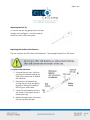
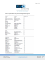
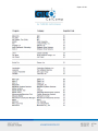
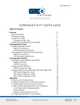
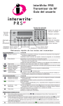
Super L III 1 Super L III 2 Table of Contents Standard Operating Information Parts Checklist What You Need to Use Super L III Caring for the Tablet and Transducer Cleaning the Tablet Replacing the Pen Tip Replacing the Pen Batteries Installing Super L VI Mounting a Large Super L III Tablet Connecting to Your Computer Connecting to the Power Supply Connecting the Transducer Applying Power to Super L III Configuring Your Computer Mounting the Transducer Holders Using the SuperSet Menu Configuring for Specific Application Programs Introduction to the Tablet Configuration Utilities Communication Options Output Format Options Mode Options Using the Tablet Configuration Utilities Controlling the Alarm Controlling the Alarm Using Remote Commands Resetting Super L III Tablet Power/Proximity LED Super L III Tones Troubleshooting Guide Procedure A: Begin Troubleshooting Procedure B: Troubleshooting Procedure C: Troubleshooting Using GTCOTEST Reducing Monitor Interference Changing the Frequency of the Cordless Cursor 5 5 5 5 5 6 6 8 8 8 8 9 9 9 10 10 10 21 21 21 22 23 25 25 26 26 26 27 28 29 30 31 32 32 Super L III 3 Changing the Frequency of the Cordless Pen Tablet Checklist Computer Checklist Software Checklist Troubleshooting Chart Super L III Specifications Advanced Operating Information Super L III Interfacing Character Format and Baud Rate Cabling Flow Control Remote Commands GTCO Super L III Commands Functional Control Commands Format Selection Commands Alarm Commands Diagnostic Commands Programming Example CalComp Emulation Commands Summagraphics Emulation Commands Command Mode Basics A Hint for Programmers Advanced Programming Information Coordinate Formats Binary Formats GTCO/CalComp Binary Format Summagraphics Binary Format Low Resolution Binary Format Cursor Button Codes in Binary Formats ASCII Formats Cursor Button Codes in ASCII Formats Measurement Scales Digitizing Modes Point Mode Line Mode Continuous Mode 32 32 33 33 34 36 37 37 37 37 39 40 41 42 45 46 47 48 48 51 53 54 55 55 56 56 58 59 59 61 63 64 65 66 66 67 Super L III 4 Line Incremental Mode Continuous Incremental Mode Remote Request Mode Controlling the Alarm Using Remote Commands Programming Examples General Product Information Radio and Television Interference Bescheinigung des Herstellers/Importeurs Limited Warranty for Super L III 67 68 68 68 69 71 71 72 73 Super L III 5 Standard Operating Information Parts Checklist Super L III Series digitizer with attached Controller Transducer (cursor or stylus) Power supply Computer interface cable with 9-pin connector and 9 to 25 adapter TabletWorks CD, which includes an electronic User’s Manual NOTE: Super L III Controller is the small enclosure attached to the back of the tablet. The Controller contains the electronics that drive the digitizer. What You Need to Use Super L III Computer with an RS-232C communication port Graphic application software that accepts digitizer input Caring for the Tablet and Transducer Follow these precautions at all times to avoid damaging your Super L III: Avoid discharging static electricity to the tablet. Do not place heavy objects on the tablet surface. Do not use sharp objects; such as compasses or knives, on the tablet surface. Do not use the tablet surface for any purpose other than drawing, tracing or digitizing. Do not drill holes on any part of the digitizer or controller. Cleaning the Tablet To clean the tablet’s surface, use a soft, non-abrasive cloth. Hardened dirt can be removed with a slightly dampened cloth. Do not clean pencil lines with a soft cleanser or pencil eraser. This could create an undesirable shiny spot on the tablet’s surface that cannot be removed. Super L III 6 Replacing the Pen Tip To replace the pen tip, grasp the tip and pull straight out (see figure). Insert the new tip and press until it clicks into place. Replacing the Cordless Pen Batteries The pen requires two 393 silver oxide batteries. The average battery life is 200 hours. To replace the batteries: 1. Unscrew the pen cap. Hold the pen from the bottom and gently slide off the pen cover to expose the batteries. 2. Remove the old batteries by turning the pen over and gently tapping it, letting the batteries fall into your other hand. 3. Insert the new batteries as they are shown in the figure above (+ towards pen tip). 4. Replace the pen cover and screw the pen cap onto the pen. Super L III 7 NOTE: When you replace the pen batteries, the pen will reset to the default frequency. If you changed the frequency of the pen before replacing the batteries, you will need to do so again after replacing the batteries (see the Reducing Monitor Interference section in Troubleshooting). Replacing the Cordless Cursor Batteries The cordless cursor requires two AAA batteries. The average battery life for the cursor batteries is 2,000 hours. To replace the batteries: 1. Place the cursor face down in the palm of your hand. Use a Phillips screwdriver to remove the two screws located on the bottom of the cursor (see figure). Remove the cursor base. 2. Remove the old batteries from the battery casings. 3. Place the new batteries in the casings, matching the polarity of each battery with the markings on the connector strips (match + to +). 4. Reposition the cursor base. Replace the screws with the Phillips screwdriver. NOTE: When you replace the cordless cursor batteries, the cursor will reset to the default frequency. If you changed the frequency of the cursor before replacing the batteries, you will need to do so again after replacing the batteries (see the Reducing Monitor Interference section in Solving Problems). Super L III 8 Installing Super L III The following topics provide instructions for putting the Super L III system together and attaching it to your computer. NOTE: Before you begin, please take a moment to fill out and mail the Warranty Registration Card or register your digitizer on our website at http://www.gtcocalcomp.com/warranty-information. Mounting a Large Super L III Tablet Super L III can be placed on a table, desk or drafting table. Alternatively, you can mount a tablet on a workstation stand available from a variety of manufacturers. Instructions will be packed with the stand. GTCO CalComp by Turning Technologies also provides Universal Mounting Brackets, as an option that allow the digitizer to be mounted to virtually any pedestal. Contact GTCO CalComp by Turning Technologies for price and availability. NOTE: Do not drill holes in any GTCO CalComp by Turning Technologies tablet. Drilling holes in any part of the tablet will void the warranty and may result in the purchase of a new tablet. Connecting to Your Computer Connect the round end of the serial cable to the jack labeled “I/O” on the Controller. The arrow on the connector should face up. Attach the 9-pin or 9- to 25-pin connector to the serial port on back of your computer. Connecting the Power Supply Connect the power supply’s cable to the jack on back of the serial cable’s connector. Plug the power supply into a power outlet or power strip. Super L III 9 Connecting the Transducer Six standard transducers are available for the Super L III. Cordless Stylus Corded Stylus Cordless 4-button Cursor Corded 4-button Cursor Cordless 16-button Cursor Corded 16-button Cursor If you are using a corded transducer, attach the connector to the jack labeled POINTER on the tablet’s Controller. Applying Power to Super L III With the wall mount power supplies, Super L III is powered when the unit is plugged into the outlet and the power switch is turned On. If you have a desktop supply, turn on the power supply switch. Super L III performs a self-test and responds with a series of tones when powered up. When you apply power, you should instantly hear four short “Success!” tones and simultaneously see the green prox light in the upper right corner of the tablet flash four times. This response indicates that the Super L III is functioning properly. If you hear any tones before the “Success!” tones or if you do not hear the four “Success!” tones or if the lights on the transducer do not flash four times, there is a problem. Carefully review the installation step-by-step and correct any errors. If there is still a problem, go to the Troubleshooting section of this manual. Configuring Your Computer Apply power to the computer. Configure your graphic application software to operate with Super L III. Many application programs provide configuration information for specific digitizers. If the GTCO CalComp by Turning Technologies Super L III digitizer is not listed, you can use the configuration for GTCO Digi-Pad Type 5 or Type 5A (T5/T5A), CalComp 3400, Summagraphics Microgrid III or ID Series. If necessary, install the appropriate digitizer driver(s) from the TabletWorks CD supplied (AutoCAD, Windows and mouse drivers are included). NOTE: Install only the drivers that are necessary for Super L III to work with your application software. Super L III 10 Mounting Transducer Holders Each transducer comes with a holder. Remove the protective paper, exposing the adhesive layer on the bottom of the holder. Place the holder in a convenient location on the tablet, outside the marked active area. Using the SuperSet Menu Configuring for Specific Application Programs To Configure Super L III for Use with Specific Application Programs: 1. In Table 1, select the application program you will be using with Super L III. Note the corresponding SuperSet Code. a. If your application program is not listed in Table 1, find the configuration settings that apply to your application program in Table 2 and use that SuperSet Code. b. If an appropriate SuperSet Code is not listed in Table 2, then use the Tablet Configuration Utilities to set up Super L III. 2. Select the S block on the SuperSet Menu. This lets the Super L III know you are about to set a new configuration. You will hear one short beep. NOTE: The proximity light will turn on only when the transducer is over a SuperSet Menu block that is a valid selection (for example, the proximity light will not turn on over a digit block until the S block has been selected). 3. On the SuperSet Menu, select the two digits of the SuperSet code for your application program. You will hear one short beep after the first digit. Then, following the second digit, you will hear the four short “Success!” tones informing you that Super L III has reset itself to the new configuration. The proximity light on the tablet will also flash four times. Super L III 11 To cancel a menu selection before it is complete, digitize a point in the tablet’s main active area. Three long beeps will indicate that the SuperSet selection process has been aborted. The proximity light on the tablet will also flash three times. 4. Run the corresponding application program on your computer. NOTE: Hardware flow control is not support by the Super L III Controller. If you have an application that requires this option, contact GTCO CalComp by Turning Technologies for alternatives. Flow Control Flow control is the process of regulating the traffic or flow of data between two RS-232C devices. Flow control prevents the transmission and subsequent loss of data if the receiver is not ready to accept it. Examples of devices that use flow control are: a printer to signal buffer full; a modem to indicate carrier detect; and a time-shared computer that services multiple users on a time-available basis. There are two kinds of flow control: ■ Software flow control is often used over communication links where only a 3-wire cable is used (Transmit Data, Receive Data, Ground) or over telephone lines. The sending device (such as the Super L III) will immediately stop sending data when it receives an ASCII XOFF character (CTRL-S, hex 13). Transmission will resume when it receives an ASCII XON character (CTRL-Q, hex 11). Character flow control will work with the straight through cable and the null modem cable. ■ Hardware flow control is not commonly used with digitizers and is therefore not supported by the Super L III Controller. Contact our Technical Support Department if you have hardware flow requirements. Flow control may not be needed when a terminal or digitizer is directly connected Super L III 12 Table 1: SuperSet Menu Codes for Selected Application Programs Super L III 13 Super L III 14 Super L III 15 Super L III 16 Super L III 17 Super L III 18 Table 2: Configuration Details for SuperSet Menu Codes NOTE: Max = 100 coordinates/second lpi = lines per inch lpmm = lines per millimeter Super L III 19 Super L III 20 Super L III 21 Introduction to the Tablet Configuration Utilities The Super L III with its Controller uses the Tablet Configuration Utilities to control baud rate, data format and other operating characteristics. Communication Options Baud: The rate, in bits/second, at which characters are transmitted across the RS232C serial interface. Choices are: 1200, 2400, 4800, 9600, 19200 or 38400. Data Bits: Data bits represent the actual data being sent from one device to another. Both devices must be set for the same number of data bits. Choices are: Seven (7) or Eight (8). Stop Bits: Each character has one or two stop bits, which tell the receiving device that a character is complete. The number of stop bits usually does not matter. Setting for two stop bits instead of one may overcome a mismatch in parity or data bits. Choices are: One (1) or Two (2). Parity: One bit can be allocated for parity (parity is a simple error-detecting scheme). Both devices (sending and receiving) must be set for the same parity – either odd parity or even parity – or they must be set for no parity. Choices are: None (N), Even (E) or Odd (O). Output Format Options GTCO: Selects GTCO-compatible formats. See Advanced Programing Information for greater detail on GTCO format structure. Choices are: Binary or ASCII. CalComp: Selects CalComp-compatible formats. See Advanced Programming Information for greater detail on CalComp format structure. Choices are: Binary, ASCII 1, ASCII 2, ASCII 3 or ASCII 4. Summa: Selects Summagraphics-compatible formats. See Advanced Programming Information for greater detail on Summagraphic format structure. Choices are: Binary or ASCII. Super L III 22 ASCII formats can be modified by including or excluding a button code, decimal point, carriage return or line feed, depending on whether GTCO, CalComp or Summa formats have been selected. Button: Defines whether the Pushbutton (Pb) value is included in the ASCII output report. This option is available only with GTCO formats. Choices are: Include or Exclude. Space: Defines whether the Space (Sp) character (hex 20) is included in the ASCII output report as a delimiter between the X and Y coordinate values. This option is available only in GTCO formats. Choices are: Include or Exclude. Decimal: Defines whether the period character (hex 2E) is included in the ASCII output report between the units and tenths digits. This option is available only in Summagraphics formats. Choices are: Include or Exclude. Return: Defines whether the Carriage Return (CR) character (hex 0D) is included in the ASCII output report as a terminator. This option is available in GTCO and Summagraphics formats. Choices are: Include or Exclude. Line Feed: Defines whether the Line Feed (LF) character (hex 0A) is included in the ASCII output report as a terminator. This option is available in GTCO, CalComp and Summagraphics formats. Choices are: Include or Exclude. Mode Options Mode: Defines how output reports are sent from the digitizer. Choices are: Point, Line, Continuous, Line Incremental or Continuous Incremental. Rate: Determines how fast output reports will be transmitted from the digitizer. Choices are: 12, 50 or 100 reports per second. Resolution: The smallest reported value returned by the digitizer. Choices are: 1000 lpi, 2000 lpi, 4000 lpi, 40 lpmm, 100 lpmm or 150 lpmm. See the Advanced Programming Information section for more details. Super L III 23 Using the Tablet Configuration Utilities If your application is not represented in the SuperSet Menu and does not have a SuperSet Code or if a different configuration is required, you can use the Tablet Configuration Utilities to structure the Super L III. The Tablet Configuration Utilities replace the 24 switches that were associated with older Type 5A Controller and the Custom Configuration Menu Card used with the Super L II Plus. Configurations you set up can be stored in any of ten user-definable SuperSet locations (codes 90 through 99) for recall at a later time. This allows the Super L III to be easily switched between applications. To Configure the Super L III with the Tablet Configuration Utilities: 1. Make sure Super L III is plugged into a Serial Port, powered on and all the tablet drivers have been uninstalled or disabled. 2. Install the Tablet Configuration Utilities from TabletWorks CD, or download them from www.gtcocalcomp.com. 3. After installation is complete, run the Tablet Configuration Utilities from the Programs list under GTCO CalComp by Turning Technologies TCU. 4. The Tablet Configuration Utilities will begin searching the Serial Ports for a supported tablet. a. If the tablet is found, information about the tablet will display under Device Info near the bottom of the screen. b. If the tablet is not found, a message will appear under Device Info near the bottom of the screen. i. If Wintab files were found, it is possible that the TabletWorks driver has the Serial Port open. ii. If the Serial Port is open by another application, it will not be displayed under System Info. Close any application or uninstall any driver that is using the Serial Port and select Refresh System Info from the File dropdown list at the top of the screen. Click on the Serial Port icon under System Info to search that Serial Port. 5. Once the Super L III has been found on a Serial Port, select Advanced Configuration from the Options dropdown list at the top of the screen. a. If Advanced Configuration is not an option, make sure Wintab Compatible Driver is not listed under Device Info. Super L III 24 6. Select a predefined (01-89) SuperSet Codes or select one of the User Defined (90-99) SuperSet Codes to customize. a. User Defined (01-89) SuperSet Codes are initially read from the tablet when the Advanced Configuration screen opens. This is to prevent loss of custom settings. Selecting Read Current Settings from the Options menu will: i. Read the Power-Up settings and User Defined SuperSet Codes from the tablet. ii. Overwrite all Custom Settings not yet saved to the tablet. b. Restore Factory Settings from the Options menu will prompt for: i. Power-Up settings reset to factory default and set current. ii. User Defined SuperSet Codes cleared and reset to factory default. 7. After making your selections, choose one of the following from the File menu at the top of the screen. a. Save Temporary Settings will configure the tablet as shown until the tablet is powered off, reset or another SuperSet Code is selected. i. After saving temporary settings, select File/Exit to test with other applications. This will leave the tablet configured to the temporary settings selected and close the Serial Port, enabling other applications to communicate with the tablet. b. Save Power-Up Settings will configure the tablet as shown. Every time the tablet is powered off and back on or reset, it will restore these settings. c. Save Custom Settings will reconfigure all nine of the tablet’s User Defined SuperSet Codes to the settings specified in the corresponding SuperSet Code dropdown list. i. You can use the SuperSet Menu on the tablet with the tablet’s transducer to activate these configurations (S + 90-99). 8. When you have finished, select Exit or Close from the File menu. a. Exit will close the Tablet Configuration Utilities. b. Close will exit the Advanced Configuration Screen and return to the Tablet Configuration Utilities window. Super L III 25 Controlling the Alarm There are five ways to toggle the alarm on or off and set the tone: Select the SuperSet Menu Alarm block (which toggles the alarm tone on and off). Use the following remote commands. Controlling the Alarm Using Remote Commands An alarm (audio tone) is provided so Super L III can inform you of certain conditions. The alarm can be enabled or disabled by the SuperSet Menu or commands. To hear only critical tones, turn the alarm off: SuperSet Menu: Select the Alarm menu block – the fat left block showing a speaker. Three medium length tones will be heard when digitized. GTCO Commands: Send command AD. To hear all tones, turn the alarm on: SuperSet Menu: Select the Alarm menu block. Three medium length tones will be heard when digitized. Then, a tone will be heard each time a transducer button is pressed. GTCO Commands: Send command AE. When you move the cursor over the Alarm block on the SuperSet Menu, the Proximity indicator (green) will light if the alarm is currently enabled. Super L III 26 Resetting Super L III There are four ways to reset Super L III: Enter SuperSet code 00 on the SuperSet Menu Turn the power switch off and back on Unplug and re-plug power supply Send remote commands described in the Advanced Operating Information section When one of these events occurs, the Super L III will revert to the configuration that was last defined. Any remote commands that were active before the reset will be lost. Tablet Power/Proximity LED The tablet led will be on when the tablet is on and transducer is awake and in the active area. Super L III Tones Super L III produces an “alarm” in the form of audio tones to notify users of various events. The table below describes the kinds of tones you may hear while operating the digitizer. Super L III 27 Troubleshooting Guide As with any computer peripheral, Super L III problems sometimes do occur. This troubleshooting guide provides clear instructions for finding and solving all common Super L III issues. In a majority of cases, you will be able to quickly resolve the problem yourself by following the below steps. 1. Install properly first. This troubleshooting guide assumes you have already correctly installed Super L III according to the detailed instructions in the Installing Your Super L III section. If you have not followed the step-by-step instructions in that section, do so now. 2. Work through the troubleshooting flowcharts on the following pages in this troubleshooting guide. 3. If your system still does not work. Call GTCO CalComp by Turning Technologies Technical Support Department at 1.866.746.3015. Be prepared to discuss the observations you made while troubleshooting. A Technical Support Specialist will help you resolve the problem as quickly as possible. NOTE: Refer to the Super L III Tones table on the previous page while using this guide. The following troubleshooting tools are included in this section: Troubleshooting Flowcharts Using GTCOTEST Super L III 28 Procedure A: Begin Troubleshooting Super L III 29 Procedure B: Troubleshooting Super L III 30 Procedure C: Troubleshooting Super L III 31 Using GTCOTEST GTCOTEST is a program that runs on the PC. It can be used to perform communication and diagnostic tests on an installed Super L III. GTCOTEST is provided on the TabletWorks CD with your system. 1. Select SuperSet Code 01 on Super L III (9600, N, 8, 1, GTCO Binary, 1000 lpi, Cont, 100). 2. To run GTCOTEST, insert the TabletWorks CD in the CD-ROM drive. GTCOTEST will work only if no Wintab drivers are installed. From the directory listing of the CD, switch to the folder that contains the gtcotest.exe files. Type gtcotest and follow the on-screen instructions. 3. Once GTCOTEST’s third screen has been reached, the pull-down menu headings will read: Communications, Diagnostics, Setup and Check Output. Select Read Switches in the diagnostics window. Communication has been established if 0’s and 1’s appear in the display box. If GTCOTEST displays the Serial input timeout error message, try selecting another COM port in the Communications window. If GTCOTEST displays the Cannot open COM port error message, try selecting another COM port in the Communications window. (Each PC serial port has a physical address that corresponds to a specific COM port. If there is only one serial port installed in the computer, it will be assigned as COM 1regardless of its physical address. GTCOTEST examines only the physical address.) Once communication is established, select the Read Tablet Size and Read Version options, making a note of the responses. This can easily be done with your print screen key if a printer is connected to your computer. Select Check Output and then choose High Res Binary. Place the transducer in the active area on the tablet. If everything is working properly, you should see data displayed on the computer screen in the following format: p XXXXXX YYYYYY P = pushbutton code XXXXXX = X coordinate data YYYYYY = Y coordinate data Super L III 32 When you move the transducer around the active area, the X and Y coordinate data should change. When you press different cursor buttons, the pushbutton code should change. If GTCOTEST indicates that the digitizer is functioning properly, check your software application setup and SuperSet code for accuracy. If you have any questions about your results or need assistance running GTCOTEST, contact our Technical Support Department. Reducing Monitor Interference If you are experiencing monitor interference with your tablet, reduce the interference by changing the frequency the transducer uses. Transducers with the following FCC ID numbers support two frequencies: ECPPPP ECPPP2, ECPPLTP, ECPPCURSOR4, ECPPCURSOR16 and ESPPCURSORII. Transducers with FCC ID numbers other than those listed must have frequencies changes at GTCO CalComp by Turning Technologies. Changing the Frequency of the Cordless Cursor 1. Place the cursor on the tablet surface. 2. Press Buttons 1 and 2 simultaneously and hold for approximately three seconds. 3. The cursor turns itself off. You will know the cursor is off when the power light on the tablet is off. 4. The cursor turns on again at the new frequency. You will know the cursor is on when the power light glows steadily. To return to the default frequency, repeat the above process. When you replace the cursor batteries, the cursor automatically resets to the default frequency. Changing the Frequency of the Cordless Pen Press both side buttons and the tip simultaneously and hold for approximately three seconds. To return to the default frequency, repeat the above process. When you replace the pen batteries, the pen resets to the default frequency. Tablet Checklist Is the tablet power supply plugged into the serial connector and into a live outlet? Is the tablet power switch on? Does the power light glow steadily when the transducer is inside the drawing area? Does it blink when the transducer is outside the drawing area? Super L III 33 The power light will blink if the transducer has gone into sleep mode. Press any button on the transducer to activate it. If the power light continues to blink and the transducer is in the drawing area, change the battery. Are all cable connections tight? Power cable to serial connector? Pointer cable to tablet? Serial cable to tablet? Serial cable to computer? Check that the cable is connected to the serial port specified in your software package. Is the tablet set up according to the software recommendations? Are any of the connector cables or receptacles damaged? Check for bent pins, cut insulation and loose wires. Computer Checklist Is the computer plugged into a live outlet? Did you turn on the computer? Does the computer work with any software? Try one of your other programs. If the computer has a diagnostic diskette, use it. Is your software package installed correctly? Does the serial port work? The only way to test the port without special equipment is to reinstall something that has worked in the past and test if it still works. Have there been any recent electrical storms in your area that may have damaged your equipment? Software Checklist Does the tablet work with some software? If your tablet currently works with some software packages, you know that the tablet, serial port and computer work. Even if the software package you are trying to install and the software that is working both support the same devices, it does not always mean that you can use the same tablet settings. The output format may be the same, but the communications protocol, resolution, operating mode and data rate may be different. Check your software’s requirements. Call the software manufacturer. The software package may have an error with another component of your system. Super L III 34 Did the software work in the past? If the software package worked with the tablet in the past, then the problem lies with the new setup. Check all the connectors. Is the tablet still plugged into the same port? If yes, reset the tablet by turning the power switch OFF and ON. Also, you may want to restart the software. Did you reset or power down the computer? During reset and power on, the computer can send meaningless characters out the serial port and this can disable the tablet. Reset the tablet again. Have you installed any new software or hardware? Remove it from your system and see if the problem goes away. Did you move any cables? Have you updated the software or its drivers? Did you reinstall the software, perhaps after a problem with your hard drive? Double check your installation procedure and the driver you selected. Reinstall the software from its master diskettes or CDs. The program files may have been corrupted. Troubleshooting Chart The following table lists common Super L III problems, their causes and their solutions. Problem Frozen screen pointer Cause Pointing tool is in sleep mode. Solution Press any button on the tool. Tablet plugged into the wrong serial port on the computer. Check that the serial port used is correctly identified in your software application. Tablet not powered correctly. Check that the power cable is installed correctly. Batteries low in pointing tool. Replace the batteries in the pointing tool. Super L III 35 Screen pointer appears to shake or jitter Unable to use the entire tablet surface Software application set up incorrectly. Check that the tablet is identified in your software application. Another device is connected to a COM port that shares the same IRQ as the tablet COM port (i.e., tablet is connected to COM1 IRQ4 and the modem is connected to COM3 IRQ4). Move one of the devices to another COM port. Contact your system manufacturer for assistance in relocating the device. Tablet is set too close to the screen monitor. Move the tablet farther away from the screen. Tablet’s frequency setting may conflict with the display. Alternate the pointing tool’s frequency. (See Reducing Monitor Frequency.) Incorrect format selected. Check your selections using the Tablet Configurations Utilities. Software application set up incorrectly. Check that the tablet is identified in your software application. Super L III 36 Super L III Technical Specifications Technology Resolution Absolute Accuracy Repeatability Proximity Self-Diagnostics Operating Modes Baud Rates Power Supply Operating Temperature Humidity Range Storage Temperature Altitude Range Certifications Cursor Switches Emulations Patented electromagnetic Up to 2540 lpi or 100 lpmm real resolution ± 0.010 inch 1 lease significant bit 1.0 inch (25.4 mm) on corded transducers and .400” on cordless transducers Automatic testing of tablet, drive electronics and microprocessor Point, line, continuous, line incremental, continuous incremental and remote request 1200, 2400, 4800, 9600, 19200 and 38400 100/120/220/240 VAC, 50/60 Hz 12 to 17 VDC 200 ma. 2.1 mm monoplug with positive outside diameter 5° to 46° C (41° to 115° F) 10% to 90%, non-condensing -18° to 68° C (0° to 150° F) 0 to 10,000 feet (0 to 3077 meters) UL, CSA, FCC-B, VDE-B Elastomeric keypad, rated life over 1 million actuations GTCO T5A, CalComp 3400, Summagraphics Microgrid Super L III 37 Advanced Operating Information Super L III Interfacing NOTE: The following information is not required for normal Super L III operation. Connecting Super L III to a computer is a simple operation (see the Installing Super L III section in this manual). If you do not have a typical interfacing situation, the information in this section will help you set up the Super L III and connect it to another device. Super L III is equipped to communicate via RS-232C, a widely used serial interface between computers and peripherals. RS-232C is a standard interface, and cables and connectors are available from a variety of sources. Most computers and peripherals either have an RS232C interface or can be equipped with one. A mini-tutorial on RS-232C interfacing This section provides basic information about RS-232C communications. There are three areas to consider when using RS-232C: Character Format and Baud Rate Cabling Flow Control Character Format and Baud Rate Character format and baud rate govern how bits are assembled to form characters and the speed of transmission. Both Super L III and the computer must have identical formats and rates. These parameters are discussed in the Introduction to the Tablet Configuration Utilities section. Cabling Cabling carries the data from one device to the other. A majority of RS-232C cables have either male 9-pin or 25-pin subminiature D connectors on their ends to match female connectors on the equipment. Super L III is supplied with an 8-pin-mini-din-to-9-pin-D serial cable and a 9-pin-to-25-pin adapter. Super L III 38 Data Terminal Equipment (DTE), such as printers, digitizers and computers, usually (but not always) transmit data on Pin 2 and receive data on Pin 3. Data Communications Equipment (DCE), such as modems, generally transmits data on Pin 3 and receives data on Pin 2. Thus, connecting a terminal (DTE) to a modem (DCE) may be as simple as connecting them with a straight-through cable that is wired pin-to-pin (i.e., 1 to 1, 2 to 2, etc.). The figure below shows such a cable. The Super L III Controller is typically connected in this manner using the cable supplied by GTCO CalComp by Turning Technologies. Connecting DTE to DTE or DCE to DCE may require a different strategy to get the data on the correct wires. The figure below shows a cable that can work in this situation. It is called a null modem cable and it fools both devices into thinking they are talking with the right kind of receiver. This cable routes Pin 2 to Pin 3 and Pin 3 to Pin 2. Super L III 39 Your computer may have a 25-pin RS-232C connector, rather than a 9-pin connector. If so, use the 9- to 25-pin adapter supplied with Super L III. This figure shows how this adapter is wired internally. Flow Control Flow control is the process of regulating the traffic or flow of data between two RS-232C devices. Flow control prevents the transmission and subsequent loss of data if the receiver is not ready to accept it. Examples of devices that use flow control are: a printer to signal buffer full; a modem to indicate carrier detect and a time-shared computer that services multiple users on a time-available basis. Super L III 40 There are two kinds of flow control: Software flow control is often used over communication links where only a 3-wire cable is used (Transmit Data, Receive Data, Ground), or over telephone lines. The sending device (such as Super L III) will immediately stop sending data when it receives an ASCII XOFF character (CTRL-S, hex 13). Transmission will resume when it receives an ASCII XON character (CTRL-Q, hex 11). Character flow control will work with the straight through cable and the null modem cable above. Hardware flow control is not commonly used with digitizers and is therefore not supported by the Super L III Controller. Contact our Technical Support Department if you have hardware flow requirements. Flow control may not be needed when a terminal or digitizer is directly connected to a single-user computer. Most digitizing application software does not use flow control of either kind. Remote Commands NOTE: The following information is not required for normal Super L III operation. Super L III can receive commands from other devices through its RS-232C port. Commands cause the Super L III to change the way it operates, to use certain coordinate formats and to do other things directed by you or by an application program. Commands offer another way to control Super L III operation besides the Tablet Configuration Utilities. Certain Super L III functions can be carried out only through commands. If you are developing your own application software, be cautious about using commands in your program. An interruption in power to the Super L III or a Reset will cause it to discard any command changes it has received. This could leave the program confused about what the Super L III is doing. A full system reset would then be needed to get the digitizer and computer coordinated again. Super L III 41 Super L III responds to three kinds of commands: GTCO CalComp by Turning Technologies Super L III standard commands (with some omissions and additions) CalComp emulation commands Summagraphics emulation commands The topics listed below describe each kind of command. GTCO CalComp by Turning Technologies Super L III commands CalComp emulation commands Summagraphics emulation commands Command Mode basics GTCO CalComp by Turning Technologies Super L III Command Summary Super L III 42 Functional Control Commands Reset Code: RS The Reset command will reset the Controller to the last known configuration, clearing all previous commands sent to the Controller. If a SuperSet Menu configuration has been selected, the Reset command will reset the Controller to the SuperSet Menu value. Select Point Mode Select Line Mode Select Continuous Mode Select Line Incremental Mode Select Continuous Incremental Mode Select Remote Request Mode Code: PT Code: LN Code: CN Code: IC Code: CL Code: RM Super L III 43 Read Current Coordinate Code: hex 02 (Ctrl-B) The Read Current Coordinate causes Super L III to output a coordinate while it is in Remote Request Mode. This command can be sent to the Super L III only when it is digitizing and only when Remote Request Mode has been selected by command RM. The Read Current Coordinate command will be ignored if the Super L III is in Command Mode. Please note that this command is not two ASCII characters. It is the one-byte-long STX character, CTRLB (hex 02). Super L III responds to the Read Current Coordinate command by transmitting one format. Set Increment Value Code: IV In Line Incremental and Continuous Incremental modes, the Super L III outputs a coordinate when the transducer is moved beyond a certain incremental distance in either the X or Y direction. The default increment is 0.01”. The Set Increment Value command allows the user to select the distance which the transducer must move to initiate coordinate output. It works as follows: 1. 2. 3. 4. Enter Command Mode by sending a CTRL-A. After receiving the > prompt, send IV and a <CR> (hex 0D). The Controller will respond with a <. After receiving the <, send a three-digit string ranging from 000 to 999. This string represents an increment value of 0.000 to 0.999 inch. 5. When the Controller receives the last character it will respond with a > prompt and await the next command. Send Coordinates 0,0 When Transducer is Out of Active Area Code: OP No Output When Transducer is Out of Active Area Code: IP Certain situations require that the Super L III be able to send a coordinate when the transducer is out of the active area. Command OP permits coordinates to be sent under this condition. Since valid coordinates are not available when the transducer is out of the active area, coordinates 0,0 are substituted in the format. When this command has been executed, digitizing modes operate normally, whether the transducer is in the active area or not. Command IP returns Super L III to the default condition, in which coordinates are sent only when the transducer is in the active area. Super L III 44 Set Digitizing Rate Code: Rx Coordinates can be sent from Super L III at rates from 5 to 100 coordinates per second. The second character in this command sets the rate, as shown in the table below. Actual rates are limited by the communication baud rate and coordinate type you have selected. The rates shown here are, therefore, maximum rates. Rate Commands Digitizing rate, formats/second Digitizing rate command 12 100 100 R1 R2 R3 5 R4 10 R5 50 R6 Change Mode Character Code: MC Some applications may have a predefined meaning for the SOH (CTRL-A) character used to invoke Command Mode. If so, invoking Command Mode may cause your system to do something else. You can set the Super L III so that a character other than SOH is used to begin Command Mode. Here is how to make the substitution: 1. Enter Command Mode. 2. Send MC, followed by a <CR>. Super L III responds with the prompt message: ENTER NEW COMMAND MODE CHARACTER: 3. Enter the desired mode change character. The new mode character can be any character except ESC (CTRL-[, hex 1B), <CR> (CTRL-M, hex 0D), CAN (CTRL-X, hex 18), VT (CTRL-K, hex 0B), XON (CTRL-Q, hex 11) or XOFF (CTRL-S, hex 13). Now, when you want to enter the Command Mode, send the new character. All other command operations remain unchanged. Select English Measurement Scale Code: IN Select Metric Measurement Scale Code: MT Invoking these commands causes Super L III to scale coordinates in the desired measurement system. The digitizer measures in only one scale at a time. See Measurement Scales for additional information on how scale selection affects coordinate data. Enable Echo Mode Code: EM Disable Echo Mode Code: hex 0F (Ctrl-O) These commands control echoing by the Super L III. When enabled, echoing transmits each received character back to the sending device. Super L III 45 Format Selection Commands ASCII Format Output Code: AS Command causes coordinates to be transmitted in ASCII. ASCII coordinates can be modified by the Low/High/Highest Resolution, Pushbutton, Space, Carriage Return and Line Feed commands and by menu settings. Binary Format Output Code: BI Command causes coordinates to be transmitted in binary format. Binary coordinates can be modified by the Low/High/Highest Resolution commands and by menu settings. Low Resolution Code: LR Command modifies ASCII and binary formats. If ASCII formats have been selected, the Low Resolution command causes the least significant digit to represent 0.01 inch or 0.1 millimeter, depending on whether English or metric scale has been selected. Both X and Y portions of each ASCII format will be four digits long if in English scale or five digits long if in metric scale. If the binary format is selected, the least significant bits represent 0.005 inch or 0.1 millimeter, depending on whether English or metric scale has been selected. High Resolution Code: HR Command modifies ASCII and binary formats. If ASCII formats have been selected, the High Resolution command causes the least significant digits to represent 0.001 inch or 0.025 millimeter, depending on whether English or metric scale has been selected. Both X and Y portions of each ASCII format will be six digits long. If binary formats have been selected, the least significant bits represent 0.001 inch or 0.025 millimeter, depending on whether English or metric scale has been selected. Super L III 46 Highest Resolution Code: H1 Command modifies ASCII and binary formats. If ASCII formats have been selected, the Highest Resolution command causes the least significant digits to represent 0.0005 inch or 0.01 millimeter, depending on whether English or metric scale has been selected. Both X and Y portions of each ASCII format will be six digits long. If binary formats have been selected, the least significant bits represent 0.0005 inch or 0.01 millimeter, depending on whether English or metric scale has been selected. Pushbutton Include Pushbutton Exclude Code: PI Code: PE Space Include Space Exclude Code: SI Code: SE Carriage Return Include Carriage Return Exclude Code: CI Code: CE Line Feed Include Code: LI Line Feed Exclude Code: LE These commands control the presence of the corresponding characters in ASCII formats. Pushbutton codes and where they appear in coordinates are described in the Advanced Programming Information section. When included, the space is an additional character separating the X and Y components of the coordinate data. When included, the LINE FEED is an additional character following the <CR>. Alarm Commands Enable Alarm Code: AE Disable Alarm Code: AD These commands enable or disable the audible alarm. When enabled, a short tone will sound when a transducer switch is pressed. When disabled, the alarm will not sound in response to transducer switch presses, but it may be sounded by remote commands and will be active during diagnostics and in the menu modes. Super L III 47 Sound Tone Code: T1 Tone Pause Code: T0 The Sound Tone command allows a remote device to sound the Super L III’s audible alarm. Tone Pause provides a pause between tones. Tones and pauses are in 0.25 second intervals. Tone commands are not affected by the Disable Alarm command. Diagnostic Commands Transmit Version Number Code: VR Command causes Super L III to determine and transmit the version number of the firmware currently installed. Display Tablet Active Area Size Code: SZ Super L III automatically determines the size of the attached tablet’s active area when it is turned on or reset. This command can be used to send the information to another device. The size is encoded as four digits: two digits representing vertical size in inches followed by two digits representing horizontal size in inches. For example, the 36” x 48” Super L III sends the digits 3648 in response to this command. Super L III 48 Programming Example: To Send Version Command and Display Results This QBASIC program interacts with Super L III in Command Mode. In this example, the program activates Command Mode, sends the VR command and displays the resulting firmware version transmitted by the Super L III. 1. Configure Super L III for 9600, N, 8, 1, GTCO ASCII and Point (SuperSet 42). 2. Enter and run this QBASIC program: CalComp Emulation Commands Super L III recognizes a subset of the CalComp 3400 command set. Space does not permit a detailed description of CalComp commands. However, most of the commands in this subset have equivalent Super L III commands. For further information about the operation of those commands, please refer to the Super L III command or function description in the GTCO CalComp by Turning Technologies Super L III Command Summary. NOTE: CalComp commands must be terminated with a <CR>, which is not shown in the codes listed here. Commands can be strung together by substituting an @ character for the <ESC>% sequence after the first command and postponing the <CR> until the end of the multiple command string. Super L III 49 Super L III 50 Super L III 51 Summagraphics Emulation Commands Super L III recognizes a subset of the Summagraphics UIOF command set. Space does not permit a detailed description of Summagraphics commands. However, most of the commands in this subset have equivalent Super L III commands. For further information about the operation of those commands, please refer to the Super L III command or function description in the GTCO CalComp by Turning Technologies Super L III Command Summary. Super L III 52 Super L III 53 Command Mode Basics To enter GTCO CalComp by Turning Technologies Command Mode: Send an ASCII CTRL-A (hex 01) character to Super L III. When Super L III receives the CTRLA, two things happen: Digitizing stops and new coordinates are not generated. If Command Mode is invoked during transmission of a coordinate, that coordinate transmission will be completed. Super L III sends a “>” (hex 3E) as a prompt to the commanding device. Super L III is now ready to accept commands. A command consists of two upper case ASCII letters or numbers followed by a delimiter. The delimiter lets the Super L III know the command is complete. There are two kinds of delimiters: <CR> (carriage return, hex 0D): indicates end of current command and more commands will follow. If the command just sent is valid, it will be carried out. The Super L III then sends another > prompt and awaits the next command. <ESC> (escape, hex 1B): indicates end of current command and no more commands will follow. If the command is valid, it will be carried out. Then Super L III will exit Command Mode and return to Digitizing Mode. If you are entering several commands, end each one with a carriage return delimiter. After each <CR>, the Super L III carries out the command and sends a new command prompt. Super L III 54 After the last command or if you are entering only one command, use an <ESC>. The Escape delimiter takes you directly back to Digitizing Mode. If the command entered is not recognized as a valid command, it will be ignored and Super L III will send a “?” (question mark). If the delimiter following an invalid command was an <ESC> (indicating your desire to leave Command Mode), Super L III stays in the Command Mode, awaiting a valid command. A command may be aborted before entering a delimiter by sending a CTRL-X (hex 18). The Super LIII then ignores the preceding one or two characters and responds with a new prompt. To Leave Command Mode: Send an <ESC> (hex 1B). The <ESC> may follow a command code or it can be sent in response to the Super L III’s prompt. Super L III returns to digitizing, now operating according to the commands sent to it. A Hint for Programmers Here is the most efficient method for sending commands: 1. Send the CTRL-A and wait until the Controller responds with the prompt >. A loop that retrieves one byte at a time from the serial port and checks for the > is best. 2. Send the command one character at a time. The Controller will respond by echoing each character. Waiting for the character to be echoed will ensure that the Controller has received the character and is waiting for the next one. 3. Once the command is complete, send a <CR> or <ESC> (hex 1B) to exit command mode. 4. If you send a <CR>, go into a loop and grab one byte at a time until a > prompt is received. Then continue sending commands as described in step 2. Super L III 55 Advanced Programming Information NOTE: The following information is not required for normal Super L III operation. If you are programming for the Super L III product line, the topics listed below will be useful: Coordinate Formats Measurement Scales Digitizing Modes Controlling the Alarm Using Remote Commands Programming Examples These topics refer to commands that put Super L III in a different operating state. The Remote Commands section contains detailed information about remote commands. Command emulations for CalComp and Summagraphics digitizers are invoked automatically when a particular format is selected via the Custom Configuration Card or the SuperSet Menu selection. However, only Super L III commands are referenced in this section. Coordinate Formats Coordinate format refers to the way Super L III encodes XY coordinate information before it sends the data out through a communication interface. The Super L III and your application program must speak the same coordinate “language” for information to be properly transferred. You have three basic format choices to make: GTCO versus CalComp or Summagraphics emulation Binary versus ASCII coordinates Coordinate resolution The topics below describe the formats available and show you how to select them. If you are developing your own software, these sections will also help you choose a format that suits your needs. Super L III 56 Binary Formats Binary formats encode coordinate information compactly. Binary coordinate formats are shorter than ASCII formats, transmit faster and take up less space if stored. On the other hand, binary formats cannot be directly displayed on a terminal or printed-they must be converted first into displayable characters. Binary formats use the high order bit in each byte as a synchronization bit. The first byte in each format has its high order bit set to 1. The remaining bytes have their high order bits set to 0. The application program must examine the high order bit of each byte to determine when a format begins. Super L III can produce two kinds of binary formats: one is compatible with GTCO Super L III and CalComp digitizers, and the other is compatible with Summagraphics digitizers. They are quite different and are described separately in the following topics. GTCO/CalComp Binary Format Summagraphics Binary Format Low Resolution Binary Format Cursor Button Codes in Binary Format GTCO/CalComp Binary Format This six-byte format is compatible with the GTCO Super L III high resolution binary format. It also emulates the CalComp binary format. Table 4 shows the structure of this format at the bit level. Super L III 57 Table 4: GTCO/CalComp High Resolution Binary Format To set up the GTCO/CalComp Binary Format: Tablet Configuration Utilities: 1. Select GTCO Binary or CalComp Binary (under Output Format Options). 2. Choose the desired resolution (under Mode Options). GTCO Commands: 1. Send command BI for Binary format. 2. Send command IN for English or command MT for metric measurements. 3. Send command HR for 1000 lpi/40 lpmm or command H1 for 2000 lpi/100 lpmm resolution. Super L III 58 Summagraphics Binary Format This eight-byte format is compatible with the Summagraphics 2000 lpi UIOF format. Table 5 shows the structure of this format at the bit level. To set up the Summagraphics Binary Format: Tablet Configuration Utilities: 1. Select Summa Binary (under Output Format Options). 2. Choose the desired resolution (under Mode Options). Table 5: Summagraphics Binary Format Super L III 59 Low Resolution Binary Format Low resolution binary format conforms to an existing industry standard method of encoding small digitizer coordinate data. It is a fast, efficient and commonly used format. Low resolution binary formats are appropriate for applications needing low precision and using tablets up to 20” x 20”. This format is five bytes long and is frequently transmitted at 9600 baud. It is used whenever the system resolution is set to 100 lpi, 200 lpi or 10 lpmm. Table 6 shows the structure of this format at the bit level. Table 6: GTCO Low Resolution Binary Format Cursor Button Codes in Binary Formats Cursor button codes are always included in binary formats. You can define certain pushbuttons on your transducer to represent information that is relevant to your task. For example, the buttons on a 4-button cursor could represent four line widths or four colors. Super L III 60 By examining the button code in the format, the application program can use this information appropriately. Binary formats include five bits which encode the button. The bits transmitted in the format depend on the button pressed. Table 7 and Table 8 show which bits will be sent. Table 7: Cursor Button Codes for 4-Button Cursor Table 8: Cursor Button Codes for 16-Button Cursors Super L III 61 ASCII Formats ASCII is a commonly used method for encoding text. ASCII coordinate formats can be directly displayed on most printers and terminals, and can be easily handled by QBASIC programs. On the other hand, ASCII coordinate formats are longer than binary ones, so they take longer to transmit and they occupy more space when stored in memory. Table 9, Table 10 and Table 11 show the range of ASCII formats available on the Super L III. Besides the GTCO formats, emulations are provided for CalComp (in four variations) and Summagraphics ASCII formats. All the formats are influenced by the resolution currently in effect (higher resolutions require an additional digit of X and an additional digit of Y). Depending on the format, you can also choose to include or exclude certain optional characters (cursor button code, space, decimal point, carriage return and line feed). To set up basic ASCII Formats: Tablet Configuration Utilities: 1. Select GTCO ASCII, CalComp ASCII 1-4 or Summagraphics ASCII (under Output Format Options). 2. Select an English or metric resolution (under Mode Options). GTCO Commands: 1. Send command AS for ASCII format. 2. Send command IN for English or command MT for metric measurements. 3. Send command LR for 100 lpi/10 lpmm, command HR for 1000 lpi/40 lpmm or command H1 for 2000 lpi/100 lpmm resolution. Then, you still have more decisions to make regarding the optional characters. Each of the optional characters can be selected by using the Tablet Configuration Utilities or by Remote Command. Check Tables 9, 10 and 11 to determine which optional characters can be included in the format you have selected. To include a Cursor Button Code, Space, Decimal Point or Line Feed in an ASCII Format (where permitted): Super L III 62 Tablet Configuration Utilities: Select the “Include” option for the corresponding character. GTCO Commands: Send command PI to include the Cursor Button Code character. Send command SI to include the Space character. Send command CI to include the Carriage Return character. Send command LI to include the Line Feed character. To remove a Cursor Button Code, Space, Decimal Point or Line Feed in an ASCII Format (where present): Tablet Configuration Utilities: Select the “Exclude” option for the corresponding character. GTCO Commands: Send command PE to exclude the Cursor Button Code character. Send command SE to exclude the Space character. Send command CE to exclude the Carriage Return character. Send command LE to exclude the Line Feed character. Table 9: GTCO ASCII Formats Super L III 63 Table 10: CalComp ASCII Formats Table 11: Summagraphics ASCII Formats Cursor Button Codes in ASCII Formats When the cursor button code is included in an ASCII format, the character transmitted in the format depends on the button pressed. Table 7 and Table 8 show which character will be sent. Instructions in the previous sections show how to include or exclude the cursor button character in certain of the ASCII formats. Super L III 64 Measurement Scales You can choose either English or metric scaling for the coordinates you digitize. Super L III applies the required conversion factor before constructing a coordinate format for output. The numbers appearing in coordinate formats depend on resolution. Table 12 shows how the resolution settings affect the data in coordinate formats. To set the measurement scale: Tablet Configuration Utilities: Select a resolution in the “Resolution” column of Mode Options. GTCO Commands: 1. Send command IN for English or command MT for metric measurements. 2. Send command LR for 100 lpi/200 LPI/10 lpmm, command HR for 1000 lpi/40 lpmm or command H1 for 2000 lpi/100 lpmm resolution. Metric example: The distance between two points is 2032 counts in the 40 lpmm binary format. Each count represents 0.025 mm (from Table 12). Then, 2032 counts x 0.025 mm/count = 50.8 mm. Table 12: Measurement Scales Super L III 65 Digitizing Modes Digitizing mode refers to the method Super L III uses to determine when to output a coordinate format. Six digitizing modes are available, but only one can be used at a time: Point Mode Line Mode (sometimes called Switched Stream Mode) Continuous Mode (sometimes called Stream Mode) Line Incremental Mode Continuous Incremental Mode Remote Request Mode Table 14 will help you compare digitizing modes. Table 14: Results of Active Area and Pushbutton Changes in Digitizing Modes Super L III 66 Table 13: Rate Commands Point Mode In Point Mode, one coordinate is sent when a transducer button is pressed. Output occurs only when the transducer is in the active area. To select Point Mode: Tablet Configuration Utilities: Select the Point option under Mode. GTCO Commands: Send command PT. Line Mode In Line Mode, coordinates are sent as long as a transducer button is pressed. Output occurs only when the transducer is in the active area. To select Line Mode: Tablet Configuration Utilities: Select Line Mode. GTCO Commands: Send command LN. To set the rate at which coordinates are sent in Line Mode: Tablet Configuration Utilities: Select 12, 50 or 100 under Rate. GTCO Commands: Send command Rx (where x = 1-6), as shown in Table 13. Super L III 67 Note that digitizing rate is also dependent on the communication baud rate and format type you have selected. The rates shown in Table 13 are therefore maximum rates. Surprisingly, if your system seems to respond slowly to digitizer input, it may be because the digitizer coordinate output rate is set too high. This may occur when a program buffers excess coordinate data, thus causing a time delay. Continuous Mode In Continuous Mode, coordinates are sent continuously, at the specified output rate. Output occurs only when the transducer is in the active area. Output occurs continuously, whether or not a transducer button is pressed. To select Continuous Mode: Tablet Configuration Utilities: Select the “Cont” option under Mode; select 12, 50 or 100 under Rate. GTCO Commands: Send command CN; to select a rate, send command Rx (where x = 1-6), as shown in Table 13. Line Incremental Mode In Line Incremental Mode, one coordinate is sent when the transducer is moved farther than a preset increment and a transducer button is pressed. Default increment is 0.01”. Output occurs only when the transducer is in the active area. To select Line Incremental Mode: Tablet Configuration Utilities: Select the “Line Incr” option under Mode. GTCO Commands: Send command IC; to set a new increment value, send command IV and at the prompt, send three digits representing the new increment in units of 0.001”. Super L III 68 Continuous Incremental Mode In Continuous Incremental Mode, one coordinate is sent when the transducer is moved farther than a preset increment or a transducer button is pressed or released. Default increment is 0.01”. Output occurs only when the transducer is in the active area. To select Continuous Incremental Mode: Tablet Configuration Utilities: Select the “Cont Incr” option under Mode. GTCO Commands: Send command CL; to set a new increment value, send command IV and at the prompt, send three digits representing the new increment in units of 0.001”. Remote Request Mode In Remote Request Mode, one coordinate is sent when the Controller receives a Read Current Coordinate command (CTRL-B). To select Remote Request Mode: Tablet Configuration Utilities: Not available. GTCO Commands: Send command RM. Controlling the Alarm Using Remote Commands An alarm (audio tone) is provided so the Super L III can inform you of certain conditions. The alarm can be enabled or disabled by the SuperSet Menu or commands. To hear only critical tones, turn the alarm off: SuperSet Menu: Select the Alarm menu block GTCO Commands: Send command AD. Super L III 69 To hear all tones, turn the alarm on: SuperSet Menu: Select the Alarm menu block. GTCO Commands: Send command AE. When you move the cursor over the Alarm block on the SuperSet Menu, the Proximity indicator (green) will light if the alarm is currently enabled. Programming Examples: Reading and Displaying Super L III Formats The following example QBASIC programs will allow you to experiment with reading and displaying Super L III formats: To read high resolution binary formats To read ASCII formats Programming Example: To Read High Resolution Binary Formats 1. Configure Super L III for 9600, N, 8, 1, GTCO Binary and Continuous (SuperSet 01). 2. Enter and run this QBASIC program: Super L III 70 Programming Example: To Read ASCII Formats 1. Configure the Super L III for 9600, N, 8, 1, GTCO ASCII and Continuous (SuperSet 74). 2. Enter and run this QBASIC program: Super L III 71 General Product Information Radio and Television Interference The user is cautioned that any changes or modifications not expressly approved by the party responsible for compliance could void the user’s authority to operate the equipment. This equipment has been tested and found to comply with the limits of a Class B digital device, pursuant to Part 15 of the FCC rules. These limits are designed to provide reasonable protection against harmful interference in a residential installation. This equipment generates, uses and can radiate radio frequency energy and, if not installed and used in accordance with the instructions, may cause harmful interference to radio communications. However, there is no guarantee the interference will not occur in a particular installation. If this equipment does cause harmful interference to radio or television reception, which can be determined by turning the equipment off and on, the user is encouraged to try to correct the interference by one or more of the following measures: Reorient or relocate the receiving antenna. Increase the separation between the equipment and the receiver. Connect the equipment into an outlet on a circuit different from that to which the receiver is connected. Reorient or coil cables. Consult the dealer or an experienced Radio/TV technician for help. NOTE: Any cables the user adds to the device must be shielded to be in compliance with the FCC standards. Any unauthorized modification to this device could result in the revocation of the end user’s authority to operate this device. Super L III 72 Bescheinigung des Herstellers/Importeurs Heirmit wird bescheinigt, dass der/die/das Super L III (Geraet, Typ, Bezeichnung) im Uebereinstimmung mit den Bestimmungen der Vfg 1046/1984 (Amtsblattverfuegung) Funk-Entstort ist. Der Deutschen Bundespost wurde das Inverkehrbringen dieses Geraetes angezeigt und die Berechtigung zur Ueberpruefung der Serie auf Einhaltung der Bestimmungen eingeraumt. GTCO CalComp by Turning Technologies, Inc. (Name des Herstellers/Importeurs) Dieses Geraet wurde einzeln sowohl als auch in einer Anlage, die einen normalen Anwendungsfall nachbildet, auf die Einhaltung der Funkentstoerbestimmungen geprueft. Es ist jodoch moeglich, dass die Funkentstoerbestimmungen unter unguenstigen Umstaenden bei anderen Geraetekombinationen nicht eingehalten werden. Fuer die Einhaltung der Funk-entstoerbestimmungen seiner gesamten Anlage, in der dieses Geraet betrieben wird, ist der Betrieber verantwortlich. Einhaltung mit betreffenden Bestimmungen kommt darauf an, dass geschirmte Ausfuhrungen gebraucht werden. Fuer die beschaffung richtiger Ausfuhrungen ist der Betrieber verantwirtlich. Super L III 73 Limited Warranty for Super L III GTCO CalComp by Turning Technologies, Inc. warrants these products to be free from defects in material and workmanship under the following terms. Complete and return the enclosed warranty registration card to ensure that your products are covered with this warranty. Coverage Parts and labor are warranted for two (2) years from the date of the first consumer purchase for the digitizer tablet, controller, transducers and tablet accessories. Power supply and cables are also warranted for two (2) years. This warranty applies to the original consumer purchaser only. Within the European Union, the warranty period is two (2) years, as mandated by the EU. Contact your local dealer or distributor for additional warranty information. Warranty is only valid if original consumer’s purchase or lease date is less than or equal to six months from the original GTCO CalComp by Turning Technologies sale date. This information will be captured by the system serial number and confirmed by the reseller’s purchase order. A nominal Warranty Handling Fee will be charged after the first 90 days of use and calculated from the date of original consumer purchase. This payment may be made by Visa, MasterCard or American Express. A copy of the sales receipt or invoice will be required for warranty verification. Conditions Except as specified below, this warranty covers all defects in material or workmanship in the products. The following are not covered by the warranty: 1. Any product on which the serial number has been defaced, modified or removed (if applicable). 2. Damage, deterioration or malfunction resulting from: a. Accident, misuse, abuse, neglect, fire, water, lightning or other acts of nature, unauthorized modification for any purpose, unauthorized product modification, or failure to follow instructions supplied with the product. b. Repair or attempted repair by anyone not authorized by GTCO CalComp by Turning Technologies. c. Any damage in shipment of the product (claims must be presented to the carrier). d. Any other cause which does not relate to a manufacturing defect. 3. Any product not sold or leased to a consumer within six months of GTCO CALCOMP BY TURNING TECHNOLOGIES original sale date. Super L III 74 GTCO CalComp by Turning Technologies will pay all labor and material expenses for covered items, but will not pay for the following: 1. Removal or installation charges. 2. Costs for initial technical adjustments (setup), including adjustment of user controls. 3. Certain shipping charges. (Payment of shipping charges is discussed in the next section of this warranty.) 4. Packaging costs. (Customers should keep their boxes.) Warranty Service Procedures 1. To obtain service on your GTCO CalComp by Turning Technologies product, contact the Technical Support Department to receive a Return Material Authorization Number (RMA#) and shipping instructions by calling: 1-866-746-3015. 2. Ship the product to GTCO CalComp by Turning Technologies with the RMA# marked clearly on the outside of the box. Without a clearly marked RMA# on the shipping box, GTCO CalComp by Turning Technologies reserves the right to refuse the shipment. 3. Although you must pay any shipping charges to ship the product to GTCO CalComp by Turning Technologies for warranty service, GTCO CalComp by Turning Technologies will pay the return shipping charges for ground shipment. Other shipping options are available at an additional fee. 4. Whenever warranty service is required, the original dated sales invoice (or a copy) must be presented as proof of warranty coverage and should be included in shipment of the product. Please also include your name, address, telephone number, fax number, email address and a description of the problem. 5. If GTCO CalComp by Turning Technologies determines that the unit is not defective within the terms of the warranty, the consumer shall pay the cost of all freight charges, as well as any repair charges. Technical Support Web-based Technical Support is available free of charge at: www.gtcocalcomp.com, where current driver releases, as well as comprehensive technical support, troubleshooting, Technical Bulletins and FAQs can be found. Telephone Technical Support is available free of charge to the original consumer for a period of 90 days from the date of purchase of the product. Please contact our Technical Support Department at: 1-866-746-3015 or fax your request to: 480.998.1751. Disclaimer of Unstated Warranties The warranty printed above is the only warranty applicable to this purchase. ALL OTHER WARRANTIES, EXPRESS OR IMPLIED, INCLUDING, BUT NOT LIMITED TO, THE IMPLIED WARRANTIES OF MERCHANTABILITY AND FITNESS FOR A PARTICULAR PURPOSE ARE DISCLAIMED. Assuming the Super L III 75 warranty above stated is otherwise applicable, it is expressly understood and agreed that GTCO CalComp by Turning Technologies sole liability whether in contract, tort, under any warranty, in negligence or other shall be for the repair or replacement of the defective parts and under no circumstances shall GTCO CalComp by Turning Technologies be liable for special, indirect or consequential damages. The price stated and paid for the equipment is a consideration in limiting GTCO CalComp by Turning Technologies liability. Notice Some states and provinces do not allow the exclusion or limitation of incidental or consequential damages, so the above exclusion may not apply to you. This warranty gives you specific legal rights, and you may have other rights, which vary from state to state, or province to province. To obtain service on your GTCO CalComp by Turning Technologies product, call our Technical Support Department at: 1-866-746-3015 or fax us at (480) 998-1751. We can also be contacted through our website at www.gtcocalcomp.com (in US); at [email protected] (in Germany); at [email protected] (in France). Important! All products returned to GTCO CalComp by Turning Technologies for service must have prior approval in the form of a Return Merchandise Authorization Number (RMA#), which can be obtained by calling the Technical Support Department. Super L III 76 Corporate Headquarters 14557 N. 82nd Street Scottsdale, Arizona 85260 Tel: 1-866-746-3015 Support: 1-866-746-3015 Fax: 480-998-1751 Support: 1.866.746.3015 Copyright© 2014 GTCO CalComp by Turning Technologies, Inc. Super L III is a trademark of GTCO CalComp by Turning Technologies, Inc. All other products and company names are the trademarks or registered trademarks of their respective owners. The information contained in this document is subject to change without notice. GTCO CalComp by Turning Technologies assumes no responsibility for technical, or editorial errors, or omissions that may appear in this document, or for the use of this material. Nor does GTCO CalComp by Turning Technologies make any commitment to update the information contained in this document. This document contains proprietary information which is protected by copyright. All rights reserved. No part of this document can be photocopied or reproduced in any form without the prior, written consent of GTCO CalComp by Turning Technologies, Inc.