1
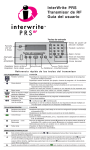
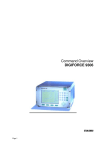
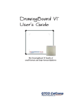
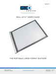
SummaSketch FX 1 Table of Contents Part I Chapter 1 Chapter 2 Installing and Using the Tablet Preparing for Use Caring for the SummaSketch Tablet 2 2 6 Part II Chapter 1 Chapter 2 Chapter 3 Chapter 4 Chapter 5 Chapter 6 Using the Drivers/Utilities Software Introduction to the Drivers/Utilities Software Guidelines for Installing the Drivers AutoDesk Application Driver Summagraphics Tablet Driver/Mouse Emulator Windows Driver (WinTab Compliant) Configuring AutoCAD Release 12 for Windows 7 7 8 9 15 18 27 Part III Chapter 1 Chapter 2 Chapter 3 Summagraphics Utilities Resetting the Tablet (MMRST and UIOFRST) Testing the Tablet (MMTEST) Changing Tablet Formats (MM.COM, UIOF.COM and SEND.COM) 30 30 32 33 Part IV Appendix A Appendix B Appendix C Appendix D Appendix E Appendices Introduction to the Drivers/Utilities Software MM/SummaSketch Format Command Summary UIOF/Microgrid Command Summary TABLET.COM & TABLETMG.COM Command Options WinTab File Names and Descriptions 37 37 39 40 42 45 SummaSketch FX 2 Part I: Installing and Using the Tablet Chapter 1: Preparing for Use Unpacking the Equipment The SummaSketch FX package contains the following equipment: Tablet with clear plastic overlay Convertible transducer with batteries for cordless operation and cable for corded operation PC-compatible interface cable 25-to-9 pin serial adapter cable Power supply Drivers/utilities software User’s manual If anything is missing from the package, contact your authorized dealer or GTCO CalComp by Turning Technologies at 1.866.746.3015 or [email protected]. Connecting the Hardware Follow the below steps to installing the SummaSketch FX tablet. 1. Connect the SummaSketch FX to the computer. Plug the phone-type connector of the interface cable into the tablet’s top left marked. SummaSketch FX 3 Next, plug the other end of the interface into the serial communications port on the computer. If the computer has a 9-pin port, use the 25-to-9 pin adapter cable between the interface cable and the computer. 2. Attach the power supply to the SummaSketch FX. Plug the barrel connector of the power supply into the interface cable as shown. 3. Prepare the transducer for use. Depending on the configuration purchased, SummaSketch FX is shipped with a four, sixteen-button cursor or a three-button pressure sensitive stylus. All of the transducers can be used cordless or corded. NOTE: Be certain to power down the tablet before plugging in a corded transducer. Do not have the batteries and cable plugged into the transducer simultaneously. This could damage the transducer and void the warranty. Using the Cursor Cordless To prepare either the four or sixteen-button cursor for cordless use: A. Remove the battery door from the back of the cursor by inserting a small flathead screwdriver in the slot provided. B. Insert three (3) AAA batteries into the battery compartment as marked. Summagraphics recommends using Duracell MN2400 AAA batteries. SummaSketch FX 4 C. Replace the battery door. The cordless cursor is now ready for use with the SummaSketch FX tablet. Proceed to step four of the installation instructions. NOTE: The cordless cursor has a special energy saving feature designed to extend the life of the batteries. After approximately 5-10 minutes of non-use, the cursor will automatically shut itself off. To reactivate the cursor, simply press a button. Using the Cursor Corded To prepare either the four or sixteen button cursor for corded use: A. Remove the battery door from the back of the cursor by using a small flathead screwdriver. B. Remove the batteries if the transducer was previously used cordless. Carefully plug the four-pin connector of the cursor cable into the socket located in the battery compartment. Please note do not force the connector into the socket. The plug and socket are keyed and fit together in one direction only. If one way does not work, try the other. C. Insert the cursor cable into the groove at the bottom of the cursor making sure the round bead is lying flat inside the battery compartment. D. Replace the battery door. E. Plug the cursor cable into the top right socket on the SummaSketch FX tablet. The corded cursor is now ready for use with the SummaSketch FX tablet. Proceed to step four of the installation instructions. NOTE: Be certain to power down the tablet before plugging in a corded transducer. Do not have the batteries and cable plugged into the transducer simultaneously. This could damage the transducer and void the warranty. Using the Stylus Cordless To prepare the three-button pressure sensitive stylus for cordless use: A. Hold the stylus with the thumb resting on the clip over the battery hatch. Press on the back of the stylus until hearing a click. Using the other hand, pull the hatch off the stylus. SummaSketch FX 5 B. Insert two (2) 393 batteries and replace the battery hatch. Care should be exercised when inserting the batteries to be sure that the battery contacts are not overstressed (bent too far back). Be sure to observe the proper orientation (polarity) of the batteries. C. Replace the battery hatch by sliding it back on until fully seated. The cordless stylus is now ready for use with the SummaSketch FX tablet. Proceed to step four of the installation instructions. NOTE: The cordless stylus has a special energy saving feature designed to extend the life of the batteries. After approximately 5-10 minutes of non-use, the cursor will automatically shut itself off. To reactivate the cursor, simply press a button. Using the Stylus Corded To prepare either the three-button pressure sensitive stylus for corded use: A. Remove the battery hatch as described above. B. Remove the batteries if the transducer was previously used cordless. Carefully plug the connector of the corded stylus cable into the socket located in the battery compartment. Please note do not force the connector into the socket. The plug and socket are keyed and fit together in one direction only. If one way does not work, try the other. C. Replace the cordless battery hatch with the corded battery hatch. D. Plug the stylus cable into the top right socket on the SummaSketch FX tablet. The corded stylus is now ready for use with the SummaSketch FX tablet. Proceed to step four of the installation instructions. SummaSketch FX 6 4. Power up the SummaSketch FX. Press the on/off switch to turn the tablet on. (Pressing it again turns the tablet off). The SummaSketch FX tablet is now ready for use. The power/prox light will illuminate when the tablet is on and blink if the transducer is not within 1/2” of the tablet surface. Chapter 2: Caring for the SummaSketch FX Tablet Caring the for the SummaSketch FX Below are basic guidelines for the care and maintenance of the SummaSketch FX tablet. Turn the tablet and computer off and unplug them both before cleaning. Also, unplug the power supply. To clean the SummaSketch FX tablet, wipe with a damp, lint-free cloth and a mild detergent solution. Do not use abrasive cleaners on the tablet surface. Never disassemble the SummaSketch FX tablet. There are no user-serviceable parts inside. When you turn off the computer, also turn off the tablet. Never scratch or mar the tablet surface. Never immerse the SummaSketch tablet or accessories in liquid. Do not trace through metal or metallized paper. Do not use metal objects, such as metal or metal-edged rulers on the tablet. Cursor Care The transparent part of the cursor that encases the crosshair is called the paddle. Protect the paddle. Do not scratch, mar or separate. To clean, wipe with a lint-free cloth dampened with water. Do not use any other type of cleaner or solvent. Never immerse the cursor in liquid. Stylus Care To clean, wipe with a lint-free cloth dampened with water. Do not use any type of cleaner or solvent. Never immerse the stylus in liquid. The stylus comes with two different refill types – one standard and a spring version. In order to change the refill, carefully twist the nose about 30 degrees counterclockwise and remove. You will then be able to remove the refill by pulling it straight out. After putting in the new refill, reinstall the nose noting that the flat part is slanted 30 degrees to the top side (button side) before pushing in and twisting 30 degrees clockwise. SummaSketch FX 7 Part II: Using the Drivers/Utilities Software Chapter 1: Introduction to the Drivers/Utilities Software About the SummaSketch FX Tablet Below is information to get acquainted with the SummaSketch FX tablet. 1. What are SummaSketch Drivers? A SummaSketch driver is a program that allows the SummaSketch tablet to communicate with specific application programs. For the tablet to act as an input device, it must be able to communicate with the software. A driver converts tablet data into information that can be read, understood and used by your application. 2. Are there specific drivers for the different tablet formats? Drivers are written for specific tablet formats and work with these tablet formats only. Be sure to select the proper driver within the application software to match the tablet format. 3. What are the SummaSketch tablet formats? The tablet can operate in either of two formats: MM/SummaSketch format UIOF/Microgrid format 4. How do I change between formats? Use the software utilities provided on the SummaSketch Drivers/Utilities diskette to override the default tablet format. 5. What are the SummaSketch utilities? The SummaSketch Utilities allow for the following: Reset the tablet without turning the power off and on. Switch between MM and UIOF formats. Test the tablet to ensure that it’s working properly. Change the default tablet parameters to meet application requirements. 6. When do I need to use the utilities? To reset the tablet. You may need to reset the tablet when switching between some applications. Applications configure the tablet for their own needs. Using one of the tablet reset SummaSketch FX 8 utilities – MMRST (used with tablets configured for UIOF/Microgrid format) – clears the tablet for a new configuration. (Note that you can also reset the tablet by repowering it). To change default tablet parameters. Some applications will only support either the MM/SummaSketch format or the UIOF/Microgrid format. For example, a tablet configured for MM/SummaSketch format and wishes to use an application written for the UIOF/Microgrid format; change the default tablet format from MM to UIOF. There are two utilities for changing between MM and UIOF formats: MM.COM – Utility sets the format of a SummaSketch tablet to MM/SummaSketch. UIOF.COM – Utility sets the format of a SummaSketch tablet to UIOF/Microgrid. 7. SPECIAL NOTE FOR UIOF FORMAT USE To use the tablet in UIOF/Microgrid mode, run the UIOF utility before starting the application driver. Chapter 2: Guidelines for Installing the Drivers/Utilities The Drivers/Utilities Diskette ADIDVR – Contains the MM format and UIOF format drivers for AutoDesk® applications (both real mode and protected mode versions) TABLTDVR – Contains the MM format and UIOF format versions of the Summagraphics tablet driver/Microsoft® mouse emulator. WINDVR- Contains the MM format and UIOF format WinTab-complaint drivers for Microsoft Windows. UTILITY – Contains the following utilities: MMRST, UIOFRST, MMTEST, MM, UIOF and SEND. Making Backups Before installing any of the drivers or utilities, make a backup copy of the SummaSketch Driver/Utilities diskette. Use only your copy and store the master in a safe place. SummaSketch FX 9 DOS Prompt vs. Batch Files You may run the SummaSketch drivers and utilities by typing commands at the DOS prompt, or by creating batch files. Included are examples of running the drivers/utilities from the DOS prompt, as well as sample batch files throughout this manual. If you require additional information on batch files and how to create them, refer to the DOS user’s manual. Chapter 3: Autodesk Application Drivers MM/SummaSketch Format Drivers Use these drivers if you’ve configured AutoCAD for a real or protected mode ADI driver. NOTE: Summagraphics’ ADI drivers are less likely to encounter initialization problems when shelling out of AutoCAD. Therefore, Summagraphics recommends using the ADI drivers supplied on the Drivers/Utilities disk instead of AutoCAD’s internal drivers. Summagraphics provides both a protected mode and a real mode driver: DGPSUMMA.EXP (protected mode driver) – Use this driver if you have release 11 or 12 of the 386 DOS extender version of AutoCAD and wish to take advantage of AutoCAD’s protected mode capabilities. DGSUMMA.COM (real mode driver) – Use this driver with all DOS versions of AutoCAD. Installing the Protected Mode Driver for AutoCAD Release 11 1. Copy the driver file from the diskette to the AutoCAD directory and rename it to ADIDIG.EXP. Example: COPY A:\ADIDVR\DGPSUMMA.EXP C:\ACAD\ADIDIG.EXP 2. Start AutoCAD. The main menu will appear on the screen. 3. Select Configure AutoCAD from the screen menu. A listing of the current configuration appears on the screen. Press ENTER to proceed to the configuration menu. SummaSketch FX 10 4. At the configuration menu, choose Configure Digitizer. AutoCAD asks if you want a new digitizer. If installing for the first time, type Y and then press ENTER. A list of digitizer options appears on the screen. Choose ADI P386 digitizer and press ENTER. 5. Select the number corresponding to the tablet size and press ENTER. 6. Enter the appropriate number of buttons on your pointing device (stylus or cursor) and select ENTER. 7. You are now asked to choose the serial port to which your tablet is connected. Type COM1 or COM2 and press ENTER. 8. The configuration is now complete and you are now ready to use the Summagraphics tablet with AutoCAD. Exit to the drawing editor and enter Y to save changes. Installing the Protected Mode Driver for AutoCAD Release 12 1. Copy the protected mode drivers from the Summagraphics Drivers/Utilities diskette to the ACAD\DRV directory. Example: COPY A:\ADIDVR\DGPSUMMA.EXP C:\ACAD\DRV 2. Start AutoCAD. The AutoCAD Drawing Editor appears on the screen. 3. Type CONFIG and press ENTER. A listing of the current configuration appears on the screen. Select ENTER to proceed to the configuration menu. 4. At the configuration menu, choose Configure Digitizer. AutoCAD asks if you want a new digitizer. If installing for the first time, type Y and press ENTER. 5. Select the number corresponding to the tablet size and press ENTER. 6. Enter the appropriate number of buttons on your pointing device (stylus or cursor) and select ENTER. 7. You are now asked to choose the serial port to which your tablet is connected. Type COM1 or COM2 and press ENTER. SummaSketch FX 11 8. The configuration is now complete and you are now ready to use the Summagraphics tablet with AutoCAD. Exit to the drawing editor and enter Y to save changes. Installing the Real Mode Driver (For All Versions of AutoCAD) Copy the file DGSUMMA.COM from the Drivers/Utilities disk to the hard drive and run the driver before starting Autodesk applications. Command Syntax: DGSUMMA [COM port] [transducer] Examples For a SummaSketch FX Professional with a four-button cursor connected for COM 2, type: DGSUMMA/2/C4. Sample Batch File DGSUMMA/2/C4 CD/ACAD ACAD Installs driver Changes to the application directory ACAD Runs application ACAD Configuring AutoCAD for the Real Mode Driver After installing the Summagraphics ADI driver, start AutoCAD and follow the instructions listed below. You will need to copy the file to the c:\directory or give a correct path name. 1. If running AutoCAD Release 11, choose Configure AutoCAD from the AutoCAD main screen menu and press ENTER to proceed to the configuration menu. If running AutoCAD Release 12, type Configure at the command prompt and select ENTER to proceed to the configuration menu. SummaSketch FX 12 2. At the configuration menu, select Configure Digitizer. AutoCAD asks if you want a new digitizer. If installing for the first time, type Y and press ENTER. A list of digitizer options appears on the screen. If running AutoCAD Release 11, select Autodesk Device Interface and press ENTER. If running AutoCAD Release 12, choose ADI Digitizer and press ENTER. 3. You’re prompted for the hexadecimal interrupt code (INT0XXh)<79>. Press ENTER to accept the default of 79 and return to the configuration menu. 4. If running AutoCAD Release 11, select Exit to Main Menu and press ENTER. If running AutoCAD Release 12, choose Exit to Drawing Editor and press ENTER. 5. Type Y to save configuration changes and press ENTER. UIOF/Microgrid Format Drivers Use these drivers if you have configured AutoCAD for a real or protected mode ADI driver. NOTE: In order to use the SummaSketch FX with UIOF/Microgrid drivers, the tablet must be placed in the appropriate format. Summagraphics’ ADI drivers are less likely to encounter initialization problems when shelling out of AutoCAD. Therefore, Summagraphics recommends using the ADI drivers supplied on the Drivers/Utilities disk instead of AutoCAD’s internal drivers. Summagraphics provides both a protected mode driver and a real mode driver. DGPSUMMA.EXP (protected mode driver) – Use this driver if you have release 11 or 12 of the 386 DOS extender version of AutoCAD and wish to take advantage of AutoCAD’s protected mode capabilities. DGSUMMA.COM (real mode driver) – Use this driver with all DOS versions of AutoCAD. Installing the Protected Mode Driver for AutoCAD Release 11 1. Copy the driver file from the diskette to the AutoCAD directory and rename it to ADIDIG.EXP. Example: COPY A:\ADIDVR\DGPSUMMA.EXP C:\ACAD\ADIDIG.EXP SummaSketch FX 13 2. Start AutoCAD. The main menu will appear on the screen. 3. Select Configure AutoCAD from the screen menu. A listing of the current configuration appears on the screen. Press ENTER to proceed to the configuration menu. 4. At the configuration menu, choose Configure Digitizer. AutoCAD asks if you want a new digitizer. If installing for the first time, type Y and then press ENTER. A list of digitizer options appears on the screen. Choose ADI P386 digitizer and press ENTER. 5. Select the number corresponding to the tablet size and press ENTER. 6. Enter the appropriate number of buttons on your pointing device (stylus or cursor) and select ENTER. 7. You are now asked to choose the serial port to which your tablet is connected. Type COM1 or COM2 and press ENTER. 8. The configuration is now complete and you are now ready to use the Summagraphics tablet with AutoCAD. Exit to the drawing editor and enter Y to save changes. Installing the Protected Mode Driver for AutoCAD Release 12 1. Copy the protected mode drivers from the Summagraphics Drivers/Utilities diskette to the ACAD\DRV directory. Example: COPY A:\ADIDVR\DGPSUMMA.EXP C:\ACAD\DRV 2. Start AutoCAD. The AutoCAD Drawing Editor appears on the screen. 3. Type CONFIG and press ENTER. A listing of the current configuration appears on the screen. Select ENTER to proceed to the configuration menu. 4. At the configuration menu, choose Configure Digitizer. AutoCAD asks if you want a new digitizer. If installing for the first time, type Y and press ENTER. 5. Select the number corresponding to the tablet size and press ENTER. SummaSketch FX 14 6. Enter the appropriate number of buttons on your pointing device (stylus or cursor) and select ENTER. 7. You are now asked to choose the serial port to which your tablet is connected. Type COM1 or COM2 and press ENTER. 8. The configuration is now complete and you are now ready to use the Summagraphics tablet with AutoCAD. Exit to the drawing editor and enter Y to save changes. Installing the Real Mode Driver (For All Versions of AutoCAD) Copy the file DGMG.COM from the Drivers/Utilities disk to the hard drive and run the driver before starting Autodesk applications. Command Syntax: DGMG [COM port] [transducer] Examples For a SummaSketch FX Professional with a four-button cursor connected for COM 2, type: DGSUMMA/2/C4. Sample Batch File DGSUMMA/2/C4 CD/ACAD ACAD Installs driver Changes to the application directory ACAD Runs application ACAD SummaSketch FX 15 Configuring AutoCAD for the Real Mode Driver After installing the Summagraphics ADI driver, start AutoCAD and follow the instructions listed below. You will need to copy the file to the c:\directory or give a correct path name. 1. If running AutoCAD Release 11, choose Configure AutoCAD from the AutoCAD main screen menu and press ENTER to proceed to the configuration menu. If running AutoCAD Release 12, type Configure at the command prompt and select ENTER to proceed to the configuration menu. 2. At the configuration menu, select Configure Digitizer. AutoCAD asks if you want a new digitizer. If installing for the first time, type Y and press ENTER. A list of digitizer options appears on the screen. If running AutoCAD Release 11, select Autodesk Device Interface and press ENTER. If running AutoCAD Release 12, choose ADI Digitizer and press ENTER. 3. You’re prompted for the hexadecimal interrupt code (INT0XXh)<79>. Press ENTER to accept the default of 79 and return to the configuration menu. 4. If running AutoCAD Release 11, select Exit to Main Menu and press ENTER. If running AutoCAD Release 12, choose Exit to Drawing Editor and press ENTER. 5. Type Y to save configuration changes and press ENTER. Chapter 4: Summagraphics Tablet Driver/Mouse Emulator MM/SummaSketch Format Driver TABLET.COM enables a SummaSketch tablet to emulate a Microsoft mouse. Use when the applications’ setup menu includes a listing for TABLET.COM or Microsoft® mouse (MOUSE.COM), and the tablet is configured in MM/SummaSketch format. Installing the MM/SummaSketch Format Driver Copy TABLET.COM from the drivers/utilities disk to the hard drive and run the driver before starting the application. Command Syntax: TABLET [COM port] [transducer] [tracking] [other options] SummaSketch FX 16 NOTE: Refer to Appendix D for TABLET.COM button mapping, tracking and memory location options. Examples For a SummaSketch FX Professional with a four-button cursor connected for COM 2, type: TABLET /2/C4. Sample Batch File TABLET /2/C4 DOSSHELL Installs driver Runs the DOSSHELL environment Running the Driver from CONFIG.SYS Another way to install the driver is by including TABLET.SYS as a device driver in the CONFIG.SYS file. In doing so, the system automatically installs the driver each time you boot or turn on the system. Line Syntax DEVICE = TABLET.SYS [COM port] [transducer] [tracking] [other options] Please note that the command options are the same as those for running TABLET.COM from the DOS prompt or a batch file. Most of the command line arguments described for TABLET.COM also works for TABLET.SYS. The exceptions are the /OFF command and the memory location options /U, /E and /HI. Example For a SummaSketch FX with a four-button cursor connected to COM 1: DEVICE = TABLET.SYS /1/C4 SummaSketch FX 17 UIOF/Microgrid Format Drivers NOTE: In order to use the SummaSketch FX with UIOF/Microgrid drivers, the tablet must be placed in the appropriate format. TABLETMG.COM enables a SummaSketch to emulate a Microsoft mouse. Use when the applications’ setup menu includes a listing for TABLETMG.COM or Microsoft® mouse (MOUSE.COM), and the tablet is configured in UIOF/Microgrid format. Installing the MM/SummaSketch Format Driver Copy TABLETMG.COM from the drivers/utilities disk to the hard drive and run the driver before starting the application. Command Syntax: TABLETMG [COM port] [transducer] [tracking] [other options] NOTE: Refer to Appendix D for TABLET.COM button mapping, tracking and memory location options. Examples For a SummaSketch FX Professional with a four-button cursor connected for COM 2, type: TABLET /2/C4. Sample Batch File TABLETMG /2/C4 DOSSHELL Installs driver Runs the DOSSHELL environment SummaSketch FX 18 Running the Driver from CONFIG.SYS Another way to install the driver is by including TABLETMG.SYS as a device driver in the CONFIG.SYS file. In doing so, the system automatically installs the driver each time you boot or turn on the system. Line Syntax DEVICE = TABLETMG.SYS [COM port] [transducer] [tracking] [other options] Please note that the command options are the same as those for running TABLETMG.COM from the DOS prompt or a batch file. Most of the command line arguments described for TABLET.COM also works for TABLET.SYS. The exceptions are the /OFF command and the memory location options /U, /E and /HI. Example For a SummaSketch FX with a four-button cursor connected to COM 1: DEVICE = TABLETMG.SYS /1/C16 Chapter 5: Windows Driver (Wintab Compliant) Installing the Windows Drivers Below are instructions for installing MM/SummaSketch or UIOF/Microgrid format drivers for Microsoft Windows. Windows must be installed on the system before installing the Summagraphics Windows drivers. NOTE: In order to use the SummaSketch FX with UIOF/Microgrid drivers, the tablet must be in the appropriate format. The Windows drivers require 250 kilobytes of free hard disk space. Before installing the drivers, check for free disk space by issuing the DIR command on the target drive. DOS will respond with nnn bytes free. If there is insufficient disk space, remove or move enough files to accommodate the driver, then run the install program. 1. Insert the Summagraphics Drivers/Utilities diskette into the floppy disk drive. At the DOS prompt, type either A:[ENTER] or B:[ENTER], depending on how the drive is labeled. 2. Change to the WINDVR directory by typing: CD\WINDVR [ENTER]. SummaSketch FX 19 3. Run the INSTALL program by typing: INSTALL [ENTER]. The INSTALL program installs the drivers and the SUMMA.EXE control panel program onto the computer. The INSTALL program prompts for the following information: Hard drive where Windows is installed Name of the Windows directory Whether you want to save (by renaming) the previous version of the drivers or remove them Serial communications port to which your graphics tablet is connected INSTALL then creates a subdirectory called SUMMA under the Windows directory, copies the drivers and starts the Windows SETUP program. Refer to Appendix E for names and descriptions of installed files and lines added to your SYSTEM.INI file. 4. In the Windows SETUP program, at the System Information screen, use the up/down arrow keys to highlight the MOUSE line and press ENTER. 5. Use the up/down arrow keys to select OTHER (requires disk provided by a hardware manufacturer) and select ENTER. 6. Type the full path name of the SUMMA subdirectory under your Windows directory, e.g., C:\\WINDOWS\SUMMA [ENTER] 7. Use the up/down arrow keys to select the appropriate driver and press ENTER. Select SummaSketch WinTab Driver if you’ve previously configured the tablet for MM/SummaSketch format. Select Summagraphics UIOF WinTab Driver if you’ve previously configured the tablet for the UIOF/Microgrid format. NOTE: Some Windows 3.0 installations may experience an anomaly with the Windows Setup program. After entering the path name to the SUMMA directory, the Windows Setup program may respond with a second prompt for the location to the driver and an erroneous path name. Example: C:\WINDOWS\SUMMA\\SUMA SummaSketch FX 20 To continue, simply backspace over the erroneous path name and re-enter the proper path name. Example: C:\WINDOWS\SUMMA [ENTER] 8. On the System Information screen, confirm that the correct driver is shown on the MOUSE line. Use the up/down arrow keys to highlight “Accept the Configuration Shown Above” and press ENTER. NOTE: If reinstalling the driver, an anomaly with the Windows 3.1 Setup program may occur. After selecting the required driver, the Setup program will prompt you again for the location of the driver. To continue, simply re-enter the driver path name. Example: C:\WINDOWS\SUMMA [ENTER] 9. Follow these steps to install the Summagraphics Control Panel icon in one of the program manager groups so that it’s easily accessible from the Windows desktop. Start Windows and click anywhere in the group that you would like to locate the control panel icon in. Open the Program Manager and select NEW command from the File dropdown menu. Click on the Browse button to display the Browse dialog box. Type SU to automatically scroll up the file listing. Note that SUMMA.EXE now appears at the top. Select SUMMA.EXE from the scroll list and click OK to exit each dialog box. The SUMMA icon should appear in the group window you selected. 10. To run the control panel, double click on the SUMMA icon. The information, features and setup icons will appear in the control panel window. WinTab driver installation is now complete. Refer to the next section for details on configuring the WinTab driver. Switching between the MM and UIOF WinTab Drivers If you’re running Windows, select EXIT from the File menu in Program Manager. Issue either the MM or UIOF commands. At the DOS prompt, change to the Windows director, i.e. CD/WINDOWS [ENTER]. At the DOS prompt, type SETUP to start the Windows Setup Utility. Use the up arrow keys to highlight the MOUSE line and press ENTER. SummaSketch FX 21 Select the appropriate driver from the displayed list of mouse devices. When the Setup program prompts you to “Accept the Configuration Shown Above,” confirm that the desired driver is shown on the mouse line and press ENTER to accept the configuration. About the Summagraphics Control Panel The control panel window contains three utilities: tablet information, features and setup. Tablet Information Utility – Displays information about the tablet being used. A “units” dropdown menu allows you to view tablet information in different formats. Features utility – Displays the transducer being used. To change transducer type, click on the accompanying button. It also allows you to change pressure settings if you’re using the pressure stylus. Setup utility – Provides fields for changing the following tablet parameters: tracking mode, button assignments and tracking area. Features Utility The features utility displays the transducer being used. Selecting a transducer other than the one being used will cause unexpected results to happen. SummaSketch FX 22 Modifying Pressure Settings If using the pressure stylus with your tablet, make sure that the Pressure stylus transducer is selected in the Features dialog box. Below in the Pressure group, added controls will allow you to set the Tip Click Pressure, Sensitivity and SmartPen Enable option. If using the non-pressure stylus, the pressure controls will be greyed out and non-accessible. Tip Click Pressure – Allows you to set the mouse click threshold for the tip on the pressure stylus. The default value is 10% of maximum pressure. The minimum and maximum values are 5% and 75% of maximum pressure respectively. If you have a light touch, you might want to decrease it. If you have a heavy touch, you may want to increase it. The “Test” button allows the user to test the threshold percentage before accepting its value. The “Test” button will turn gray if you surpass the pressure threshold while clicking on it. Sensitivity – Allows you to change the amount of pressure that is passed from the stylus to the application. Use a low percentage if you have a heavy touch. Use a high percentage if you have a light touch. Note that some applications allow for this type of adjustment within a control panel or preferences dialog. In these applications, this setting will give you an even greater range of sensitivity than the application allows independently. Effects of this setting are diagrammed below. SmartPen Enable – When SmartPen is enabled, your tablet will override the default pressure settings with SmartPen pressure settings. SmartPen pressure settings are set each time you press down within the active area of the tablet with your pressure stylus. In this manner, the tablet continuously monitors the maximum pressure exerted and automatically adjusts the pressure range and pressure values accordingly. When SmartPen is disabled, the tablets’ maximum pressure setting will default to the highest nominal maximum pressure value for your stylus. SummaSketch FX 23 The Setup Utility The setup utility provides fields for changing the following tablet parameters: tracking mode, button assignments and tracking area. Each of these options are fully explained below. Modifying the Tracking Mode You may select either of two tracking modes: Relative Mode – Changes the tablet to relative tracking (like a mouse). It also activates the sensitivity control. To modify the sensitivity, use the arrow buttons or SummaSketch FX 24 type in a new value. The higher the number in the Sensitivity box, the faster the screen pointer moves. Absolute Mode – Changes the tablet to absolute tracking. The Sensitivity field deactivates and will have no effect on tracking when in absolute mode. About the Button Assignments Area Default Check Box – Indicates if the button assignments are defaults. Button Menu – Lists the buttons on the stylus or cursor. Button Function Menu – Lists the functions assigned to each stylus or cursor button. When the default box is checked, the button assignments are predetermined by the driver. Below is a listing of the default stylus/cursor buttons and their functions. Default Three-Button Stylus Functions (Pressure or Non-Pressure): Button Function (Mouse Button) Tip Left click Lower Barrel Left double click Upper Barrel Right click Default Four-Button Cursor Functions: Button Yellow White Blue Green Function (Mouse Button) Left click Left double click Right double click Right click Default Sixteen-Button Cursor Functions (UIOF Driver Only): Button Function (Mouse Button) 1 Left click 2 Right click 3 Left double click C Right double click Others [Unassigned] SummaSketch FX 25 Modifying the Tablet Active Area There are two ways to modify the tablet active area, either by entering information in the numeric fields or by using the onscreen graphics. Each of these methods are explained below. Method 1: Using the “Tracking Area” Numeric Fields Whole Tablet Check Box – Click on this button to map the entire tablet to the screen. NOTE: When this button is activated, the remaining tracking area controls are inoperative. Preserve Aspect Ratio Button – Click on this button to modify the current tablet active area so that it has the same aspect ratio as the computer screen. Aspect ratio is the ratio between the horizontal and vertical dimensions of the computer screen. The dimensions of the tablet active area defined must have the same aspect ratio as your computer screen or circles drawn on the tablet will appear as ovals on the screen and vice versa. NOTE: Aspect ratio cannot be guaranteed in a Windows environment because pixel shapes may vary from monitor to monitor, causing graphics to be distorted. You may need to make adjustments to your system to ensure proper aspect ratio. Units Menu – Specifies the measurement system used to display tablet information: Metric or English. Width and Height Controls – These fields define the size of the tablet active area. Use the arrow buttons or enter a value from your keyboard. Margin Controls – These fields define the position of the active area on the tablet. Use the arrow buttons or enter a value from your keyboard. Method 2: Using the Onscreen Graphic The tracking area box in the lower right-hand corner of the tracking area panel represents the entire tablet active area. The shaded area within this box illustrates the current userdefined active area. Position the screen pointer inside of the tracking area box and click. Two things happen: (1) the screen pointer changes from an arrow to a crosshair, and (2) the entire tracking box becomes shaded. SummaSketch FX 26 NOTE: If you do not define the active area within approximately seven seconds, the crosshair changes back to an arrow and it is necessary to click inside the tracking area box again. To define the active area, position the transducer on the lower left corner of the active area that you wish to define and click. Then position the cursor on the upper right corner of the active area. Click on TEST to test the next active area. The new active area does not take effect until you click on TEST or OK. NOTE: To aid in defining the active area, cut a piece of scrap paper to the size of the active area you wish to define and position it on the tablet and secure with tape. SummaSketch FX 27 Chapter 6: Configuring AutoCAD Release 12 for Windows This chapter assumes you’re using a template with AutoCAD. If you’re not using a template, you will need to designate a rectangular area within the active area as your screen pointing area. Configuring the Windows Driver 1. Install the tablet Windows driver as described in Part II, Chapter 5 of this manual. 2. Fasten the AutoCAD template to the tablet. 3. Start Windows. Open the Summagraphics Control Panel and double click on the Setup icon. 4. The Setup dialog box appears. In the Tracking Area field of the Setup dialog box, click in the Whole Tablet and Preserve Aspect Ratio checkboxes so that there are no checkmarks. 5. Position the screen pointer inside the black/gray box in the lower portion of the Setup dialog box and click. This box will turn completely gray. 6. Digitize the lower left dot on the template’s screen pointing area. Next, digitize the upper right dot on the template’s screen pointing area. When finished digitizing the two points, click OK to close the dialog box. Configuring AutoCAD for Windows 1. Install AutoCAD for Windows as explained in the AutoCAD Installation Guide. 2. Start AutoCAD for Windows. In the Drawing Editor, select Preferences from the File dropdown menu. 3. In the Preferences dialog box, activate the Save to ACAD.INI and the Digitizer/Mouse Arbitrate ratio buttons. Then click OK to close the dialog box and save changes. 4. Select Configure from the File dropdown menu. The current Configuration Screen appears. Press ENTER until the Configuration Menu appears. SummaSketch FX 28 5. Choose Configure Digitizer from the Configuration Menu. Then type Y and ENTER to indicate that you do want to select a different digitizer. 6. A screen listing the available digitizer drivers are displayed. Select WINTAB Compatible Digitizer ADI 4.2 by Autodesk and press ENTER. AutoCAD then displays a series of prompts. There are an infinite number of possible configurations that can be specified at this point. Summagraphics recommends using the configuration listed below. After successfully setting up the recommended configuration, feel free to try other configurations. AutoCAD Prompt: Response: Do you want to configure the digitizer as a mole? Type Y. AutoCAD Prompt: Response: Do you want an audible mole/context state indicator? Type Y if you like beeps, N if you do not. AutoCAD Prompt: Response: Do you want a visible mole/context state indicator? Type Y. AutoCAD Prompt: Response: Do you want to assign a cursor button to toggle modes? Type Y. AutoCAD Prompt: Response: Press any button except the pick button, now. Press one of the side buttons on the stylus or any button (except the pick button) on the four or 16-button cursor. AutoCAD Prompt: Response: Do you want to assign a primary mole area? Type N. AutoCAD Prompt: Response: Do you want to assign a secondary mole area? Type Y. AutoCAD Prompt: Response: Enter lower left hand corner now. Digitize the lower left hand dot on the AutoCAD templates’ screen pointing area. AutoCAD Prompt: Response: Enter upper right hand corner now. Digitize the upper right hand dot on the AutoCAD templates’ SummaSketch FX 29 screen pointing area. AutoCAD Prompt: Response: Do you want a primary toggle area? Type N. AutoCAD Prompt: Response: Do you want a secondary toggle area? Type N. 7. On the Configuration Menu, type ENTER twice to save the configuration changes and return to the drawing editor. 8. Configure the template as you normally would. Refer to the AutoCAD Interface, Installation and Performance Guide or third party template manual for detailed template configuration instructions. When finished, the template, mole area, tablet area and toggle button should be properly configured. Digitizer Mode vs. Mole Mode The tablet is initially set up in the Digitizer mode. In Digitizer mode, you can draw in the graphics area, execute template picks and operate the cursor buttons. However, you cannot access the dropdown menus, tool palette or manipulate the window; this requires the Mole mode. To enter in the Mole mode, press the button previously defined as the Toggle button. In Mole mode, you can draw in the graphics area, execute template picks, and access the dropdown menus and tool palette. However, the cursor buttons will not have the usual AutoCAD definitions. Instead, the pick button remains the pick button and the button defined as the toggle button remains a toggle button. All other buttons will produce results that are defined in the Summagraphics Windows Control Panel. SummaSketch FX 30 Part III: Summagraphics Utilities Chapter 1: Resetting the Tablet (MMRST and UIOFRST) MMRST Command The MMRST command resets a tablet that is configured for MM/SummaSketch format. NOTES: When using the BA option (Base Address), all four digits must be specified. (Example: for COM 1 - /BA03F8) This program transmits in the MM/SummaSketch default serial communication configuration: 9600 baud, 8 data bits, odd parity and 1 stop bit. Use the /BA switch only when the serial port is located at a non-standard address within the computer. A summary of command line switches are always available by starting the program with switch /? or /H. Example To reset an MM/SummaSketch format tablet connected to COM 2, type: MMRST/2. SummaSketch FX 31 UIOFRST Command The UIOFRST command resets a tablet that is configured for UIOF/Microgrid format. NOTES: When using the BA option (Base Address), all four digits must be specified. (Example: for COM 1 - /BA03F8) This program transmits in the UIOF/Microgrid default serial communication configuration: 9600 baud, 7 data bits, even parity and 2 stop bit. Use the /BA switch only when the serial port is located at a non-standard address within the computer. A summary of command line switches are always available by starting the program with switch /? or /H. Example To reset an UIOF/Microgrid format tablet connected to COM 2, type: UIOFRST/2. SummaSketch FX 32 Chapter 2: Testing the Tablet (MMTEST) MMTEST Tablet Test Utility The MMTEST utility verifies that the MM/SummaSketch or UIOF/Microgrid format tablet is working properly. NOTES: When using the BA option (Base Address), all four digits must be specified. (Example: for COM 1 - /BA03F8) Use the /BA switch only when the serial port is located at a non-standard address within the computer. A summary of command line switches are always available by starting the program with switch /? or /H. Test Results After running MMTEST, the X, Y coordinate data should be streaming on the screen. The data is in the following format: XXXXXX, YYYYYY, F, P where X is the X coordinate data and Y is the Y coordinate data. F is the number of the cursor/stylus button being pressed (1, 2, 3, 4, etc.). P is proximity; 0 is in proximity and 1 is out of proximity. Move the cursor/stylus around on the tablet surface. You should see the X, Y coordinates changing. Press each of the cursor/stylus buttons one at a time. You should see the F field changing accordingly. Lift the cursor/stylus a few inches off the tablet surface. You should see the P field change from 0 to 1. SummaSketch FX 33 If the tablet performs all of these tasks, then it is operating properly. If not, refer to Appendix A: What to do if a Problem Arises in the back of this manual. Exiting MMTEST To exit MMTEST, type: <CTRL>X Chapter 3: Changing Tablet Format (MM.COM, UIOF.COM and SEND.COM) MM Tablet Configuration Utility The MM Utility configures a tablet to MM/SummaSketch format. NOTES: When using the BA option (Base Address), all four digits must be specified. (Example: for COM 1 - /BA03F8) Use the /BA switch only when the serial port is located at a non-standard address within the computer. A summary of command line switches are always available by starting the program with switch /? or /H. Example To configure a tablet on COM 2 for MM/SummaSketch format, type: MM/2. SummaSketch FX 34 UIOF Tablet Configuration Utility The UIOF Utility configures a tablet to UIOF/Microgrid format. NOTES: When using the BA option (Base Address), all four digits must be specified. (Example: for COM 1 - /BA03F8) Use the /BA switch only when the serial port is located at a non-standard address within the computer. A summary of command line switches are always available by starting the program with switch /? or /H. Example To configure a tablet on COM 2 for UIOF/Microgrid format, type: UIOF /2. SummaSketch FX 35 SEND Tablet Configuration Utility The SEND tablet configuration utility sends a string of commands to SummaSketch tablets to modify the default tablet settings. NOTES: SEND.COM can transmit at various baud rates and parities and can transmit commands from an ASCII file. For further information, refer to SEND.DOC, or invoke SEND.COM with the Help option. (Example: SEND /?) Option /C must be the last option on the command line. There is no space between the /C switch and the commands that follow. To transmit ASCII control characters, precede a printable ASCII character with “^”. (Examples: ESC = ^[, NULL = ^@, BELL + ^G) When using the BA option (Base Address), all four digits must be specified. (Example: for COM 1 - /BA03F8) Use the /BA switch only when the serial port is located at a non-standard address within the computer. A summary of command line switches are always available by starting the program with switch /? or /H. Examples To configure a tablet on COM 1, transmitting in MM format to ASCII format output, type: SEND/1/Cza SummaSketch FX 36 To configure a tablet on COM 2, transmitting in MM format to binary format, type: SEND/2/Czb To configure a tablet on COM 1, transmitting in UIOF format to stream mode, type: SEND/1/U/C^[M0 SummaSketch FX 37 Part IV: Appendices Appendix A: What to do if a Problem Arises Problem The power/prox light is not on. Solutions 1. Check that the power switch is in the ON position. 2. Check that the power supply cable is plugged into the interface cable connector. 3. Check that the power supply is plugged into a working electrical outlet. 4. Check that the I/O cable phone connector is plugged into the proper location on the tablet. The screen cursor does not move when I move the stylus/cursor. 1. Check that the application is configured for the proper stylus/cursor. 2. Run the test program to see if you get coordinates. 3. Press a stylus/cursor button to ensure the stylus/cursor is active. 4. Reset the tablet and restart the application. 5. In cordless mode, be sure that the batteries are oriented properly and that the battery contacts are clean. The buttons on the stylus/cursor do not work. 1. Check that the application is configured for the proper tablet driver. SummaSketch FX 38 2. Press a stylus/cursor button to ensure that the stylus/cursor is active. 3. Run the test program to check if the buttons are working properly. 4. In cordless mode, be sure that the batteries are oriented properly and that the battery contacts are clean. If the problem persists, it is probably in the configuration of the application software. Contact the application developer or local dealer for assistance. If you discover that you have a tablet problem, contact the GTCO CalComp by Turning Technologies Support Team at 1.866.746.3015. SummaSketch FX 39 Appendix B: MM/SummaSketch Format Command Summary SummaSketch FX 40 Appendix C: UIOF/Microgrid Format Command Summary SummaSketch FX 41 SummaSketch FX 42 Appendix D: TABLET.COM & TABLETMG.COM Command Options Cursor/Stylus Button Mapping Options Command syntax: /CM#### Allows a user-defined mapping of the cursor/stylus buttons. The /CM argument is followed by 1-4 digits that specify which cursor/stylus switches are assigned to standard mouse buttons. Each digit represents the value of a cursor/stylus switch and its position represents the mouse button that it is assigned to. The first digit after the /CM argument corresponds to the left mouse button, the second digit to the right mouse button, the third digit to the middle mouse button and the fourth digit corresponds to an emulation of both the left and right mouse buttons being pressed simultaneously. Example: TABLET /CM2134 The above example shows cursor/stylus switch #2 being mapped to the left mouse button, cursor/stylus switch #1 being mapped to the right mouse button, cursor/stylus switch #3 being mapped to the middle mouse button and the cursor/stylus switch #4 being mapped to both the right and left mouse buttons. Tracking Options The following options will work only if the application is set up to use a Microsoft mouse (MOUSE.COM). Applications that are compatible specifically with TABLET.COM should configure tracking automatically or allow you to configure tracking through the application’s setup utility. The user of the following options will be overridden by the applications. Relative Mode /R Relative mode is the default setting. There are four relative mode options: /S## Sets both horizontal and vertical sensitivity (Range = 0 to 99, default = 50) /H## Sets only the horizontal sensitivity (Range = 0 to 99, default = 50) /V## Sets only the vertical sensitivity (Range = 0 to 99, default = 50) /P# Option is the ballistic gain profile. It controls acceleration of the screen cursor. TABLET.COM comes with four built-in ballistic gin profiles. Slow, Moderate, Fast and Uncelebrated. Specify 1, 2, 3, or 4. SummaSketch FX 43 Absolute Mode /A Absolute mode maps the tablet’s entire active area to the computer screen. Relative mode options (/S, /H, /V, /M) should not be used in Absolute mode. NOTE: Applications accept input from TABLET.COM or TABLETMG.COM as either absolute screen coordinates or relative mouse units, also referred to as mickeys. Absolute mode works only with those applications that accept input as absolute screen coordinators. To verify that absolute mode is working, position the screen pointer, then lift the cursor/stylus out of the tablet’s active area and place it at a different location on the tablet. The screen cursor should snap to a new location. If it does not, then the application works only in relative mode and the absolute mode option will have no effect. Other Options /M# Option overrides an application that changes the mouse cursor for text modes by locking the mouse cursor to the default text cursor. To enable locked cursor, type /M1; to disable locked cursor, type /M0. The default is /M0. /N# Option specifies how many screen updates to skip before actually plotting the cursor. This feature is useful for laptops and other systems with slower LCD displays. A small value is recommended because driver performance can be affected. # is a number between 0 and 225. The default is /N0. NOTES: When selecting a serial port other than 1, 2, 3 or 4, the /BA and /I options must be used together. When using the /BA option, all four digits must be specified (Example: for COM 1 /BA03F8). Use the /BA and /I options when a non-standard serial address is used in the computer. Memory Location Options /U, /E and /HI These options all you to maximize the amount of memory available for DOS application programs. Move a majority of the TABLET.COM driver to a memory location outside of the 640K area used by most application programs. The /U command shifts the driver to the upper memory area between 640K and 1MB. The /E command moves the driver into expanded memory. The /HI command shifts the driver into the high memory area between 1 MG and 1.064 MG. SummaSketch FX 44 Your computer system needs to support these options before they can be used. The designated memory must be installed as RAM. To use /E, you must have either expanded memory hardware, such as Intel Above Board or a software driver, such as EMM386 or QEMM in your machine. To use /HI, you must have a 80286, 80386 or 80486 family processor and the HIMEM.SYS driver (or equivalent) loaded before installing the mouse driver. MS-DOS 5.0 systems should also have the line DOS = UMB in the CONFIG.SYS file. Only TABLET.COM can be relocated. TABLET.SYS cannot be relocated. You cannot relocate TABLET.COM into another memory area without first removing the mouse driver by using the TABLET /OFF command. SummaSketch FX 45 Appendix E: WinTab File Names and Descriptions File Names and Descriptions While installing the WinTab Driver, the INSTALL program will create a directory named SUMMA in your Windows directory and copy the following files to it. MWTSUMG.DRV MWTSUMM.DRV VSERMD.386 OEMSETUP.INF README.TXT SMPENOFF.BAT Summagraphics MG driver Summagraphics MM driver Summagraphics virtual port manager Setup file Software information document Batch file to disable SmartPen feature INSTALL will then copy the following files into your Windows directory. SUMMA.EXE WINTAB.INI SMPENOFF.BAT Summagraphics Control Panel WinTab Driver Initialization file Batch file to disable SmartPen feature INSTALL will also copy the following file into your Windows System directory. WINTAB.DLL WinTab dynamic link library Information added to SYSTEM.INI INSTALL will write the following lines to the top of your SYSTEM.INI file; where # represents the communications port number you specified during the install procedure. [Virtual Tablet] Port = # SummaSketch FX 46 Regulatory Statements and Warranty Radio and Television Interference The user is cautioned that any changes or modifications not expressly approved by the party responsible for compliance could void the user’s authority to operate the equipment. This equipment has been tested and found to comply with the limits of a Class B digital device, pursuant to Part 15 of the FCC rules. These limits are designed to provide reasonable protection against harmful interference in a residential installation. This equipment generates, uses and can radiate radio frequency energy and, if not installed and used in accordance with the instructions, may cause harmful interference to radio communications. However, there is no guarantee the interference will not occur in a particular installation. If this equipment does cause harmful interference to radio or television reception, which can be determined by turning the equipment off and on, the user is encouraged to try to correct the interference by one or more of the following measures: Reorient or relocate the receiving antenna. Increase the separation between the equipment and the receiver. Connect the equipment into an outlet on a circuit different from that to which the receiver is connected. Reorient or coil cables. Consult the dealer or an experienced Radio/TV technician for help. NOTE: Any cables the user adds to the device must be shielded to be in compliance with the FCC standards. Any unauthorized modification to this device could result in the revocation of the end user’s authority to operate this device. Canada This digital apparatus does not exceed the Class B limits for radio noise emissions from digital apparatus as set out in the radio interference regulations of the Canadian Department of Communications. Le present appareil numérique n’emet pas bruits radioelectriques depassant les limites applicables aux appareils numériques de Classe B prescrites dans le réglement sur le brouillage radioelectrique edicte par le Ministere des Communications du Canada. SummaSketch FX 47 European Union Emission Directive This product is in conformity with the protection requirements of EU Council Directive 89/366/ECC on the approximation of the laws of the Member States relating to electromagnetic compatibility. This product has been tested and found to comply with the limits for Class B Information Technology Equipment according to CISPR 22/European Standard EN55022. The limits for Class B equipment were derived for typical industrial environments to provide reasonable protection against interference with licensed communication devices. European Union WEEE Directive The manufacture of this equipment required the extraction and use of natural resources. It may contain hazardous substances that could impact health and the environment. In order to avoid the dissemination of the hazardous substances into the environment and to diminish the pressure on our natural resources, GTCO CalComp by Turning Technologies encourages you to return this product to the appropriate take-back system facility. These facilities reuse or recycle most of the materials in this equipment in a responsible way. The crossed-out wheeled bin symbol below invites you to use these take-back systems. If you need more information about the collection, reuse and recycling systems in your area, please contact your local or regional waste authority. Further information about the responsible end-of-life management of this and other GTCO CalComp by Turning Technologies products is available on our website at www.gtcocalcomp.com. SummaSketch FX 48 Limited Warranty for SummaSketch FX GTCO CalComp by Turning Technologies, Inc. warrants these products to be free from defects in material and workmanship under the following terms. Complete and return the enclosed warranty registration card to ensure that your products are covered with this warranty. Coverage Parts and labor are warranted for one (1) year from the date of the first consumer purchase for the digitizer tablet, controller, transducers and tablet accessories. Power supply and cables are also warranted for one (1) year. This warranty applies to the original consumer purchaser only. Within the European Union, the warranty period is two (2) years, as mandated by the EU. Contact your local dealer or distributor for additional warranty information. Warranty is only valid if original consumer’s purchase or lease date is less than or equal to six months from the original GTCO CalComp by Turning Technologies sale date. This information will be captured by the system serial number and confirmed by the reseller’s purchase order. A nominal Warranty Handling Fee will be charged after the first 90 days of use and calculated from the date of original consumer purchase. This payment may be made by Visa, MasterCard or American Express. A copy of the sales receipt or invoice will be required for warranty verification. Conditions Except as specified below, this warranty covers all defects in material or workmanship in the products. The following are not covered by the warranty: 1. Any product on which the serial number has been defaced, modified or removed (if applicable). 2. Damage, deterioration or malfunction resulting from: a. Accident, misuse, abuse, neglect, fire, water, lightning or other acts of nature, unauthorized modification for any purpose, unauthorized product modification, or failure to follow instructions supplied with the product. b. Repair or attempted repair by anyone not authorized by GTCO CalComp by Turning Technologies. c. Any damage in shipment of the product (claims must be presented to the carrier). d. Any other cause which does not relate to a manufacturing defect. 3. Any product not sold or leased to a consumer within six months of GTCO CALCOMP BY TURNING TECHNOLOGIES original sale date. GTCO CalComp by Turning Technologies will pay all labor and material expenses for covered items, but will not pay for the following: 1. Removal or installation charges. SummaSketch FX 49 2. Costs for initial technical adjustments (setup), including adjustment of user controls. 3. Certain shipping charges. (Payment of shipping charges is discussed in the next section of this warranty.) 4. Packaging costs. (Customers should keep their boxes.) Warranty Service Procedures 1. To obtain service on your GTCO CalComp by Turning Technologies product, contact the Technical Support Department to receive a Return Material Authorization Number (RMA#) and shipping instructions by calling: 1-866-746-3015. 2. Ship the product to GTCO CalComp by Turning Technologies with the RMA# marked clearly on the outside of the box. Without a clearly marked RMA# on the shipping box, GTCO CalComp by Turning Technologies reserves the right to refuse the shipment. 3. Although you must pay any shipping charges to ship the product to GTCO CalComp by Turning Technologies for warranty service, GTCO CalComp by Turning Technologies will pay the return shipping charges for ground shipment. Other shipping options are available at an additional fee. 4. Whenever warranty service is required, the original dated sales invoice (or a copy) must be presented as proof of warranty coverage and should be included in shipment of the product. Please also include your name, address, telephone number, fax number, email address and a description of the problem. 5. If GTCO CalComp by Turning Technologies determines that the unit is not defective within the terms of the warranty, the consumer shall pay the cost of all freight charges, as well as any repair charges. Technical Support Web-based Technical Support is available free of charge at: www.gtcocalcomp.com, where current driver releases, as well as comprehensive technical support, troubleshooting, Technical Bulletins and FAQs can be found. Telephone Technical Support is available free of charge to the original consumer for a period of 90 days from the date of purchase of the product. Please contact our Technical Support Department at: 1-866-746-3015 or fax your request to: 480.998.1751. Disclaimer of Unstated Warranties The warranty printed above is the only warranty applicable to this purchase. ALL OTHER WARRANTIES, EXPRESS OR IMPLIED, INCLUDING, BUT NOT LIMITED TO, THE IMPLIED WARRANTIES OF MERCHANTABILITY AND FITNESS FOR A PARTICULAR PURPOSE ARE DISCLAIMED. Assuming the warranty above stated is otherwise applicable, it is expressly understood and agreed that GTCO CalComp by Turning Technologies sole liability whether in contract, tort, under any warranty, in negligence or other shall be for the repair or replacement of the defective parts and under no circumstances shall GTCO CalComp by Turning Technologies be liable for special, indirect or SummaSketch FX 50 consequential damages. The price stated and paid for the equipment is a consideration in limiting GTCO CalComp by Turning Technologies liability. Notice Some states and provinces do not allow the exclusion or limitation of incidental or consequential damages, so the above exclusion may not apply to you. This warranty gives you specific legal rights, and you may have other rights, which vary from state to state, or province to province. To obtain service on your GTCO CalComp by Turning Technologies product, call our Technical Support Department at: 1-866-746-3015 or fax us at (480) 998-1751. We can also be contacted through our website at www.gtcocalcomp.com (in US); at [email protected] (in Germany); at [email protected] (in France). Important! All products returned to GTCO CalComp by Turning Technologies for service must have prior approval in the form of a Return Merchandise Authorization Number (RMA#), which can be obtained by calling the Technical Support Department. SummaSketch FX 51 Corporate Headquarters 14557 N. 82nd Street Scottsdale, Arizona 85260 Tel: 1-866-746-3015 Support: 1-866-746-3015 Fax: 480-998-1751 Support: 1.866.746.3015 Copyright© 2014 GTCO CalComp by Turning Technologies, Inc. SummaSketch FX is a trademark of GTCO CalComp by Turning Technologies, Inc. All other products and company names are the trademarks or registered trademarks of their respective owners. The information contained in this document is subject to change without notice. GTCO CalComp by Turning Technologies assumes no responsibility for technical, or editorial errors, or omissions that may appear in this document, or for the use of this material. Nor does GTCO CalComp by Turning Technologies make any commitment to update the information contained in this document. This document contains proprietary information which is protected by copyright. All rights reserved. No part of this document can be photocopied or reproduced in any form without the prior, written consent of GTCO CalComp by Turning Technologies, Inc.