1
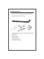
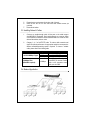
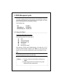
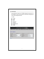
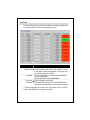
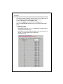
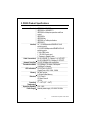
FCC Certifications This Equipment has been tested and found to comply with the limits for a Class A digital device, pursuant to part 15 of the FCC Rules. These limits are designed to provide reasonable protection against harmful interference when the equipment is operated in a commercial environment. This equipment generates, uses, and can radiate radio frequency energy and, if not installed and used in accordance with the instruction manual, may cause harmful interference to radio communications. Operation of this equipment in a residential area is likely to cause harmful interference in which case the user will be required to correct the interference at his own expense. This device complies with Part 15 of the FCC Rules. Operation is subject to the following two conditions: (1) this device may not cause harmful interference, and (2) this device must accept any interference received; including interference that may cause undesired operation. CE Mark Warning This equipment complies with the requirements relating to electromagnetic compatibility, EN 55022 class A for ITE, the essential protection requirement of Council Directive 89/336/EEC on the approximation of the laws of the Member States relating to electromagnetic compatibility. Company has an on-going policy of upgrading its products and it may be possible that information in this document is not up-to-date. Please check with your local distributors for the latest information. No part of this document can be copied or reproduced in any form without written consent from the company. Trademarks: All trade names and trademarks are the properties of their respective companies. Copyright © 2009, All Rights Reserved. Document Version 2.0 2009/04/02 Table of Content Unpacking Information .................................................................................. 1 1. Introduction ................................................................................................ 2 1.1 General Description ........................................................................................................ 2 1.2 Key Features .................................................................................................................. 3 1.3 The Front Panel .............................................................................................................. 3 1.4 The Rear Panel ............................................................................................................... 5 2. Installation .................................................................................................. 6 2.1 Desktop Installation ........................................................................................................ 6 2.2 Rack-mount Installation .................................................................................................. 6 2.3 Installing Network Cables ............................................................................................... 7 2.4 Network Application ........................................................................................................ 7 3. Functional Description............................................................................... 8 4. Management guide ..................................................................................... 9 4.1 Access the Switch........................................................................................................... 9 4.2 Home Page ................................................................................................................... 11 4.2.1 System ............................................................................... 12 4.2.2 Ports .................................................................................. 13 4.2.3 VLANS ............................................................................... 14 4.2.4 QoS ................................................................................... 15 4.2.5 Aggregation/Trunking Configuration ...................................... 16 4.2.6 Discovery ........................................................................... 17 4.2.7 Firmware Update ................................................................ 18 4.2.8 Default ............................................................................... 18 4.2.9 Reboot ............................................................................... 18 5. Product Specifications............................................................................. 19 Unpacking Information Thank you for purchasing the Datasheen D326S 24+2G Gigabit Ethernet Web Smart Switch. Before you start, please check all the contents of this package. The product package should include the following: 1. One D326S 24-Port Fast Ethernet +2-Port Gigabit Copper/Mini-GBIC Combo Web-Smart Switch 2. One power cord 3. Rubber foot and screws 4. Rack-mount brackets 5. One RS-232 Cable (Optional) 6. One CD_ROM for user’s manual 1 1. Introduction 1.1 General Description Datasheen D326S is a 24-Port Fast Ethernet +2-Port Gigabit Copper/Mini-GBIC Combo Web-Smart Switch. The device is a powerful, high-performance Gigabit Ethernet switch, which provides smart and efficient management functions and supports 26 ports connection with 24 ports of 10/100Mbps and 2 ports 10/100/1000Mbps ports that lead you to a real Gigabit connection. The 2 copper ports support fiber connection with the 2 equipped Mini-GBIC ports for obtaining long-distance communication. The NWay auto-negotiation operation automatically negotiates with the connected partners on the network speed and duplex mode; that provides an easy way to integrate 10/100Mbps networks with no pain. It is ideal for micro-segmenting large networks into smaller, connected subnets for improved performance, enabling the bandwidth demanding multimedia and imaging applications. Out of the ordinary dumb switches, the 24+2G Gigabit Ethernet Web Smart Switch embedded advanced management capability; that the device can be managed through console port or web-based UI. This is much useful for system manager to monitor and control the system efficiently. Store-and-forward switching mode promises the low latency plus eliminates all the network errors, including runt and CRC error packets. To work under full-duplex mode, transmission and reception of the frames can occur simultaneously without causing collisions as well as double the network bandwidth. The switch is plug-n-play without any software to configure and also fully compliant with all kinds of network protocols. Moreover, the rich diagnostic LEDs on the front-panel provide the operating status of individual port and whole system. 2 1.2 D326S Key Features 24 fixed 10/100Mbps Fast Ethernet ports for easy network connecting application. Support 2 fixed 10/100/1000Mbps Gigabit ports Support 2 Mini GBIC ports Provide Auto-discovery Function for easy Network management. Provide 8K MAC address entries and 26 groups port base VLAN table Support Port aggregation. Supports 3 types of QoS priority for port base, 802.1p & TCP/IP TOS/DiffServ(DS) priority field Support full duplex flow control and half duplex back pressure Store-and-forward forwarding scheme Error packet filtering Support 2.5M bits buffer Memory Support Web-based UI for configuration Internal switching power supply (100-240Vac/50-60Hz) Firmware upgrade 1.3 D326S Front Panel The front panel of the switch is shown as below LEDs Definition LED for the device The switch provides a power LED for the device. LED Power Status Steady Green Off Operation The switch is powered on The switch is powered off 3 LED for each port LED Status Green LINK/ACT Blinking Green Off Operation The port is connected. A valid link is established, and there is data transmitting / receiving. No valid link on this port. Port Operation There are 24 * 100Mbps and 2 * 1000Mbps RJ-45 / Mini GBIC (copper) ports on the front panel. The auto-negotiation feature of the switch allows each port of the device running at one of the following operation modes: Media Speed 10Mbps 10/100/1000Mbps(copper) 100Mbps 1000Mbps(Fiber) (mini GBIC required) 1000Mbps 1000Mbps Duplex Mode Full Duplex Half Duplex Full Duplex Half Duplex Full Duplex Full Duplex Note: For the last port, when both the fiber and cooper interfaces are connected, the system adapts the fiber interface and disables the relevant cooper port automatically. If the port is connected but the Port LED is dark, check the following items: The switch and the connected device’s power are on or not. The connecting cable is good and with correct type The cable is firmly seated in its connectors in the switch and in the associated device Restore Default Button You can use this button to reset the switch or restore to factory default settings. To reset the switch, press the button once. To restore factory default settings, press and hold the button for three seconds. 4 1.4 D326S Rear Panel The rear panel of the switch is shown as below: Power Receptacle To be compatible with the electric service standards around the world, the switch is designed to afford the power supply in the range from 100 to 240VAC, 50/60Hz. Please make sure that your outlet standard to be within this range. To power on the switch, please plug the female end of the power cord firmly into the receptacle of the switch and the other end into an electric service outlet. After the power cord installation, please check if the power LED is lit for a normal power status. 5 2. Installation D326S switch can be placed directly on your desktop, or mounted in a rack. Users can immediately use most of the features simply by attaching the cables and turning the power on. 2.1 Desktop Installation For desktop installation, the switch needs to put on a clean, flat desk or table close to a power outlet. Plug in all network cables and the power cord, then the system is ready. Before installing the switch, you must ensure: 1. It is accessible and cables can be connected easily 2. Cabling is away from: *Sources of electrical noise such as radios, transmitters and broadband amplifiers *Power lines and fluorescent lighting fixtures. 3. Keep water or moisture off 4. Airflow around the unit and through the vents in the side of the case is great for heat radiation (company recommend that you provide a minimum of 25 mm clearance) To prolong the operational life of your units: 1. Never stack unit more than eight sets high if freestanding 2. Do not place objects on top of any unit or stack 3. Do not obstruct any vents at the sides of the case 2.2 Rack-mount Installation D326S switch may standalone, or may be mounted in a standard 19-inch equipment rack. Rack mounting produces an orderly installation when you have a number of related network devices. The switch is supplied with rack mounting brackets and screws. These are used for rack mounting the unit. Rack Mounting the Switch in the 19-inch rack: 1. 2. 3. 4. Disconnect all cables from the switch before continuing. Place the unit the right way up on a hard, flat surface with the front facing toward you. Locate a mounting bracket over the mounting holes on one side of the unit. Insert the screws and fully tighten with a suitable screwdriver. 6 5. 6. 7. Repeat the two previous steps for the other side of the unit. Insert the unit into the 19" rack and secure with suitable screws (not provided). Reconnect all cables. 2.3 Installing Network Cables 1. Crossover or straight-through cable: All the ports on the switch support Auto-MDI/MDI-X functionality. Both straight-through or crossover cables can be used as the media to connect the switch with PCs as well as other devices like switches, hubs or router. 2. Category 3, 4, 5 or 5eUTP/STP cable: To make a valid connection and obtain the optimal performance. An appropriate cable that corresponds to different transmitting/receiving speed is required. To choose a suitable cable, please refer to the following table. Media 10/100/1000Mbps Copper 1000Mbps Fiber (Mini GBIC required) Speed 10Mbps 100Mbps 1000 Mbps 1000Mbps 2.4 Network Application 7 Wiring Category 3,4,5 UTP/STP Category 5 UTP/STP Category 5,5e UTP/STP The cable type differs from the mini-GBIC you choose. Please refer to the instruction came with your mini-GBIC. 3. Functional Description Flow Control and Back Pressure Flow control and Back Pressure both contributes for lower and higher speed devices to communicate to each other hence ensures the correctness of data transmitting. The 802.3x flow control and Back Pressure mechanisms work respectively for full and half duplex modes. Flow control can be enabled or disabled on a per-port basis. VLAN With VLAN supported, the network can be segmented in groups to reduce the collisions from widely broadcasting. The device supports port-based VLAN. Port-based VLAN classifies incoming packets to VLANs according to their ingress port. Trunk (Aggregation) The Trunk functionality integrates several ports to enlarge the bandwidth that helps to boost the backbone connectivity. The switch allows the Maximum 8(16-port)/ 12(24-port) groups and 2 or 4 members for each group. Quality of Service (QoS) The QoS service classifies packets into different precedence. The packets are transmitted and received by their classified priorities. This mechanism helps high bandwidth demanded applications such as VoIP to get an unobstructed connection. 8 4. D326S Management guide This section instructs you how to enter and set up the configurations, which can be accessed by RS-232 serial port (out-of-band) on the rear panel or by Telnet session / Internet Browser over the network (in-band). Factory Default value: IP: Subnet Mask: Default Gateway: 192.168.1.1 255.255.255.0 192.168.1.254 4.1 Access the Switch Console Port (Out-of-band) connection The operating mode of the console port is: DCE 19200 (Fix baud rate) n (No parity checking) 8 (8 Data bits) 1 (1 stop bit) None (No flow control) After attaching a RS-232 cable (Straight-through) to the serial port of a PC running a terminal emulation program, press “Enter” key then login screen appears. Enter your username and password to login the management console. Note: The management functions of console program are exactly the same with web-based management interface but in text mode. Attention: 1. The factory default value of UserName and Password is “admin” 2. System configurations via the Console Port only will be allowed by the way of master device 9 In-Band Connections (Web Browser) To manage the switch through in-band access, you should configure the management station with an IP address and subnet mask compatible with your switch. 1. Running your Web Browser and enter the IP address “192.168.1.1” as the URL in the “address” field. 2. Key in the User name and password to pass the authentication. The factory default value of User Name and Password is “admin”. 3. After authentication procedure, the home page shows up. 10 4.2 Home Page After authentication procedure, the “SYSTEM Configuration” page shows up as the Homepage. You may click the hyperlinks on the left side of each page to get access to each management functions. It includes, System Ports VLAN QoS Aggregation Discovery Firmware Update Default Reboot 11 4.2.1 System To set up the system configurations such as login value, system name and IP address. Items MAC Address User Name Password System name S/W Version IP Address Subnet Mask Gateway Functions The Mac Address of this device The login name (default admin) The login password (default admin) The name of the device The software version of this device Set up the IP of this device Set up the Subnet mask of this device Set up the Gateway of this device To save the configuration of the system, click “Apply” button. Note: After applying a new IP address, a new login page will be started automatically. Please login again to proceed to other configurations. 12 4.2.2 Ports This Port Configuration page shows the link status of each port and allows users to configure speed, flow control and bandwidth for each port. Items Admin Operate mode Bandwidth Flow Control Link/Status Functions Enable or Disable the Admin function Choose the Speed mode of port 10/100, Half/Full. If you set to auto speed, it will be auto-negotiation. (Auto Speed, 10M half, 10M full, 100M half, 100M full) Control the bandwidth; you can select the speed limitation you need in the drop list. (Disable/128K/256K/512K/1M/2M/4M/8Mbps) Enable or Disable the flow control Show the link status of each port. The column lights green with the link speed while there is valid connection on this port. To save the configuration of the system, click “Apply” button. Click on “Previous Page” or “Next Page” button to setup the other ports. 13 4.2.3 VLANS VLANS Configuration is for dividing the LAN into subnet groups for better network management. (26 VLAN groups total) Mode: 1. Disable: Turn off the VLAN function by selecting the mode. 2. Port BASE: Group the port you select by entering the group number (Ex.1) in VLAN textbox and selecting the port numbers (Ex.1, 2,3,4) you want. Buttons Add: Add the entry into the VLAN table Remove: Remove the Entry you select Modify: Modify the Entry you select Apply: Apply the Mode you select Provides web manage security function, click enable VLAN group web manage to support web manage function for VLAN group 14 4.2.4 QoS There are three modes of Quality of Service to choose, TOS, Tag Base, and Port base. To Disable the QOS, click Disable and Click apply to save. To use the TOS, select TOS and click Apply to save. To enable the Tag Base, select Tag base and click Apply to save. When you enable Port Base, packets from the port you select will have higher priority. To enable the Port base, 1. Select the port-base 2. Select the port-base ratio (1:4; 1:8; 1:16; Always High) The higher a ratio is, the higher priority the port will get. 3. Select the ports in the table (High means high Priority, and Low means Low priority). The priority depends on the Port Base rate. 4. Click apply to save 15 4.2.5 Aggregation/Trunking Configuration To set up the Port trunk groups, select “Enable” of the group you need. Don’t forget to click the “Apply” to save the setting. Supports 7 trunk groups for network application. 16 4.2.6 Discovery When you install several 24+2G Gigabit Ethernet web-smart switches, the discovery management tool helps you to search and access those switches on the LAN easily. Therefore you can access any switch on your LAN without memorizing those IP addresses. You can only find switches with the IP Address compatible with the one you access. Note. The Maximum number of Address list is 16. Auto Search 1. Click the “Auto search” button to find the switches. 2. The IP address & name of Switch list will appear. 3. Click the one you want to access. 17 4.2.7 Firmware Update To update firmware, 1. Click the update button on the Home page 2. Click “Apply” to activate. Don’t power off the switch while it’s working. 4.2.8 Default To restore to default values, 3. Click the default button on the Home page 4. Click “Apply” to activate. Don’t power off the switch while it’s working. 4.2.9 Reboot To reboot the switch, 1. Click the Reboot button on the Home page 2. Click “Apply” to activate. Don’t power off the switch while it’s working. 18 5. D326S Product Specifications Standard Interface Cable Connections Network Data Rate Transmission Mode LED indications Memory Emission Operating Temperature Operating Humidity Power Supply IEEE802.3 10BASE-T IEEE802.3u 100BASE-TX IEEE802.3x full-duplex operation and flow control IEEE802.3z IEEE802.3ab IEEE802.1p Traffic prioritization IEEE802.Q 24 * 10/100Mbps auto MDI/MDI-X RJ-45 switching ports 2*10/100/1000Mbps auto MDI/MDI-X RJ-45 switching ports 2* Mini GBIC ports 1 * RS-232 Console port 1* Restore to Default button RJ-45 (10BASE-T): Category 3,4,5 UTP/STP RJ-45 (100BASE-TX): Category 5 UTP/STP 10/100/1000Mbps Auto-negotiation 10/100Mbps: Full-duplex, Half-duplex 1000Mbps Full-duplex 10/100 Ports: Link/ ACT Gigabit Ports: 10M, 100M, 1000M 8K MAC entries 2.5M bits Buffer Memory FCC Class A CE Mark Class A VCCI-A 00 ~ 400C (320 ~ 1040F) 10% - 90% Internal power supply 100-240V/ 50-60Hz © Datasheen Corporation. 2009. Taiwan 19