1
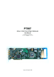
P7886 (S)(E)
2(1)(0.5) GHz Time-of-Flight / Multiscaler
User Manual
Copyright FAST ComTec GmbH
Grünwalder Weg 28a, D-82041 Oberhaching
Germany
Version 2.0, March 9, 2000
Warranty Information
Warranty Information
FAST ComTec warrants proper operation of this software only when used with software and
hardware supplied by FAST ComTec. FAST ComTec assumes no responsibility for modifications
made to this software by third parties, or for the use or reliability of this software if used with
hardware or software not supplied by FAST ComTec. FAST ComTec makes no other warranty,
expressed or implied, as to the merchantability or fitness for an intended purpose of this software.
Software License
You have purchased the license to use this software, not the software itself. Since title to this
software remains with FAST ComTec, you may not sell or transfer this software. This license
allows you to use this software on only one compatible computer at a time. You must get FAST
ComTec's written permission for any exception to this license.
Backup Copy
This software is protected by German Copyright Law and by International Copyright Treaties. You
have FAST ComTec's express permission to make one archival copy of this software for backup
protection. You may not otherwise copy this software or any part of it for any other purpose.
Copyright 1999 FAST ComTec Communication Technology GmbH,
D-82041 Oberhaching, Germany. All rights reserved.
This manual contains proprietary information; no part of it may be reproduced by any means
without prior written permission of FAST ComTec, Grünwalder Weg 28a, D-82041 Oberhaching,
Germany. Tel: ++49 89 66518050, FAX: ++49 89 66518040.
The information in this manual describes the hardware and the software as accurately as
possible, but is subject to change without notice.
ComTec GmbH
II
Important Information on Hardware Compatibility
Important Information on Hardware Compatibility
The P7888 Series Multiscalers are PCI Local Bus compliant devices. As such the board contains
the configuration space register organization as defined by the PCI Local Bus Specification.
Among the functions of the configuration registers is the storage of unique identification values for
our devices as well as storage of base address size requirements for correct operation specific to
each of our products.
The host computer that our products are installed in is responsible for reading and writing to/from
the PCI configuration registers to enable proper operation. This functionality is referred to as 'Plug
and Play' (PnP). As such, the host computer PnP BIOS must be capable of automatically
identifying a PCI compliant device, determining the system resources required by the device, and
assigning the necessary resources to the device. Failure of the host computer to execute any of
these operations will prohibit the use of the P7888 Series Multiscalers in such a host computer
system.
It has been determined that systems that implement PnP BIOS, and contain only fully compliant
PnP boards and drivers, operate properly. However, systems that do not have a PnP BIOS
installed, or contain hardware or software drivers, which are not PnP compatible, may not
successfully execute PnP initialization. This can render the P7888 Series inoperable. It is beyond
the ability of FAST ComTec's hardware or software to force a non-PnP system to operate P7888
Series Multiscalers.
ComTec GmbH
III
WARNINGS
WARNINGS
Damage to the P7886 board, the computer or injury to yourself may result if power is applied
during installation.
Static electricity discharges can severely damage the P7886. Use strict antistatic procedures
during the installation of the board.
Take care to provide ample airflow around the P7886 board.
Before connecting any input signal on to the discriminator inputs take care not to exceed the
maximum differential input voltage of ± 3.0 V between the discriminator input and the
corresponding threshold voltage (ref. chapter 3.3 and 7.2.1).
ComTec GmbH
IV
Table of Contents
Table of Contents
1. Introduction .............................................................................................................................. 1-1
2. Installation Procedure .............................................................................................................. 2-1
2.1. Hard- and Software Requirements ............................................................................. 2-1
2.2. Hardware Installation .................................................................................................. 2-1
2.3. Software Installation.................................................................................................... 2-2
2.4. Getting Started with a basic measurement................................................................. 2-3
2.4.1. Connecting the test signals ............................................................................ 2-3
2.4.2. Starting the MCDWIN and setup for a measurement .................................... 2-4
3. Hardware Description .............................................................................................................. 3-1
3.1. Overview ..................................................................................................................... 3-1
3.2. FAST-NIM Signal Inputs ............................................................................................. 3-2
3.3. +/- 2V Discriminator Inputs.......................................................................................... 3-3
3.4. SYNC Outputs............................................................................................................. 3-3
3.5. 'GO'-Line ..................................................................................................................... 3-4
3.6. Multi I/O Connector ..................................................................................................... 3-5
3.7. Timebase .................................................................................................................... 3-6
4. Functional Description ............................................................................................................. 4-1
4.1. Introduction ................................................................................................................. 4-1
4.2. Modes of Operation..................................................................................................... 4-1
4.2.1. Stop-After-Sweep Mode ................................................................................. 4-1
4.2.2. Continuous / Wrap-Around Mode................................................................... 4-1
4.2.3. Sequential Mode ............................................................................................ 4-1
4.2.4. Start Event Marker ......................................................................................... 4-1
4.3. START / Trigger Input Logic ....................................................................................... 4-2
4.4. STOP Input Logic........................................................................................................ 4-2
4.5. FIFO Concept.............................................................................................................. 4-3
4.6. Measurement Time Window and Acquisition Delay ................................................... 4-4
4.7. Sweep Counter ........................................................................................................... 4-4
5. Windows Server Program ........................................................................................................ 5-1
5.1. Control Language........................................................................................................ 5-6
5.2. Controlling the P7886 Windows Server via DDE...................................................... 5-10
5.2.1. Open Conversation ...................................................................................... 5-11
5.2.2. DDE Execute................................................................................................ 5-11
5.2.3. DDE Request ............................................................................................... 5-12
5.2.4. Close Conversation ...................................................................................... 5-13
5.2.5. DDE Conversation with GRAMS/386........................................................... 5-14
5.3. Controlling the P7886 Windows Server via DLL....................................................... 5-14
6. MCDWIN Software................................................................................................................... 6-1
6.1. File Menu .................................................................................................................... 6-2
6.2. Window Menu ............................................................................................................. 6-3
6.3. Region Menu............................................................................................................... 6-4
6.4. Options Menu.............................................................................................................. 6-7
6.5. Action Menu .............................................................................................................. 6-16
ComTec GmbH
V
Table of Contents
7. Appendix .................................................................................................................................. 7-1
7.1. Performance Characteristics....................................................................................... 7-1
7.1.1. General........................................................................................................... 7-1
7.1.2. Timebase........................................................................................................ 7-1
7.1.3. Data Throughput ............................................................................................ 7-1
7.2. Specification................................................................................................................ 7-2
7.2.1. Absolute Maximum Ratings ........................................................................... 7-2
7.2.2. Recommended Operating Conditions ............................................................ 7-2
7.2.3. Power Requirements...................................................................................... 7-2
7.2.4. Connectors ..................................................................................................... 7-2
7.2.5. Physical .......................................................................................................... 7-4
7.3. Accessories................................................................................................................. 7-4
7.4. Troubleshooting .......................................................................................................... 7-5
7.5. Personal Notes............................................................................................................ 7-6
ComTec GmbH
VI
Table of Figures
Table of Figures
Figure 2.1: Extra power supply connector .................................................................................... 2-1
Figure 2.2: add-on multi I/O port connector .................................................................................. 2-2
Figure 2.3: Basic measurement timing diagram ........................................................................... 2-3
Figure 2.4: Basic measurement setup .......................................................................................... 2-4
Figure 2.5: Bracket mounted signal connectors ........................................................................... 2-4
Figure 2.6: P7886 / MCDWIN startup window .............................................................................. 2-5
Figure 2.7: P7886 Settings window .............................................................................................. 2-5
Figure 2.8: Input Threshold window.............................................................................................. 2-6
Figure 2.9: Axis Parameter window .............................................................................................. 2-6
Figure 2.10: MCDWIN properly setup........................................................................................... 2-7
Figure 2.11: Resulting spectrum of the basic measurement ........................................................ 2-7
Figure 3.1: P7886 PCI board ........................................................................................................ 3-1
Figure 3.2: SMA connectors on the mounting bracket.................................................................. 3-2
Figure 3.3: FAST-NIM input schematic......................................................................................... 3-2
Figure 3.4: Discriminator input schematic..................................................................................... 3-3
Figure 3.5: FAST-NIM SYNC_1 output schematic ....................................................................... 3-4
Figure 3.6: 'GO'-line connector ..................................................................................................... 3-4
Figure 3.7: 'GO'-line logic circuit schematic .................................................................................. 3-5
Figure 3.8: Multi I/O port connector pinning.................................................................................. 3-5
Figure 3.9: add-on multi I/O connector ......................................................................................... 3-5
Figure 3.10: Digital I/O port circuit schematic ............................................................................... 3-6
Figure 4.1: START input logic schematic...................................................................................... 4-2
Figure 4.2: STOP input logic schematic........................................................................................ 4-3
Figure 4.3: Two step FIFO concept for highest data throughput .................................................. 4-3
Figure 5.1: P7886 Server Window ................................................................................................ 5-1
Figure 5.2: Data Operations dialog ............................................................................................... 5-2
Figure 5.3: Settings dialog ............................................................................................................ 5-2
Figure 5.4: Input thresholds dialog................................................................................................ 5-4
Figure 5.5: System Definition dialog box for a single P7886 card ................................................ 5-4
Figure 5.6: System Definition dialog box, two P7886 cards ......................................................... 5-5
Figure 5.7: Remote control dialog................................................................................................. 5-5
Figure 5.8: Opening the DDE conversation with the P7886 in LabVIEW ................................... 5-11
Figure 5.9: Executing a P7886 command from a LabVIEW application..................................... 5-12
Figure 5.10: Getting the total number of data with LabVIEW ..................................................... 5-12
Figure 5.11: Getting the data with LabVIEW .............................................................................. 5-13
Figure 5.12: Closing the DDE communication in LabVIEW........................................................ 5-13
Figure 5.13: Control Panel of the demo VI for LabVIEW ............................................................ 5-14
ComTec GmbH
VII
Table of Figures
Figure 6.1: MCDWIN main window............................................................................................... 6-1
Figure 6.2: MCDWIN Map and Isometric display.......................................................................... 6-2
Figure 6.3: ROI Editing dialog box, left: Single spectra, right: 2D spectra.................................... 6-5
Figure 6.4: Single Gaussian Peak Fit ........................................................................................... 6-6
Figure 6.5: Log file Options for the Single Gaussian Peak Fit ...................................................... 6-6
Figure 6.6: Colors dialog box ........................................................................................................ 6-7
Figure 6.7: Color Palette dialog box.............................................................................................. 6-8
Figure 6.8: Single View dialog box................................................................................................ 6-9
Figure 6.9: MAP View dialog box.................................................................................................. 6-9
Figure 6.10: Isometric View dialog box ....................................................................................... 6-10
Figure 6.11: Axis Parameter dialog box...................................................................................... 6-10
Figure 6.12: Scale Parameters dialog box.................................................................................. 6-11
Figure 6.13: Calibration dialog box ............................................................................................. 6-12
Figure 6.14: Comments dialog box ............................................................................................. 6-13
Figure 6.15: P7886 Settings dialog box ...................................................................................... 6-13
Figure 6.16: Data Operations dialog box .................................................................................... 6-14
Figure 6.17: System Definition dialog box .................................................................................. 6-14
Figure 6.18: Tool Bar dialog box................................................................................................. 6-15
Figure 6.19: Function keys dialog box ........................................................................................ 6-15
ComTec GmbH
VIII
Introduction
1.
Introduction
The P7886 PCI board is one of the fastest commercially available multiple event time digitizers. It
can be used as an ultra fast Multiscaler/TOF system in Time-of-Flight Mass-Spectrometry and
time-resolved Single Photon Counting.
The P7886 is capable of accepting one event (stop pulse) in every time bin. Burst/peak count
rates of up to 2 GHz (1 GHz @ S-version1, 0.5 GHz = 500MHz @ E-version2) can be handled
with no deadtime between timebins. A proprietary input logic securely prevents double counting.
The dynamic range of up to 37 (36 @S, 35 @E) bit enables sweeps for an incredible 68.7
seconds with a time resolution of 500 ps (1 ns @S, 2 ns @E). A crystal stabilized PLL oscillator
assures a resolution of typically 400 ps FWHM at a full scale time range of 1 ms (measured in the
last time bin of 2,000,000 time bins (1,000,000 @S, 500,000 @E) and 30 minutes acquisition
time). An optional available oven stabilized oscillator further improves long-term and temperature
stability.
A two step FIFO memory concept enables for ultra high event rate capability. Full 2 GHz (1 GHz
@S, 500 MHz @E) bursts can be buffered for at least 4 µs. The first 255 deep multi event FIFO
buffers incoming events at a maximum countrate of 2 GHz (1 GHz @S, 500 MHz @E). A second
16k deep FIFO is filled at over 18 MHz and buffers the subsequent data transfer over the PCI
bus. Data reduction is performed by recording interesting, i.e. inside a preselected time window
arriving stop events only.
For experiments requiring repetitive sweeps the spectral data obtained from each sweep can be
summed in the PC enabling extremely high sweep repetition rates. A presettable 32 bit sweep
counter enables for exact normalization calculations.
The logical combination of the FAST-NIM and ±2V discriminator inputs allows for fast gating of
START and STOP signals.
An open-drain 'GO'-line (compatible to other products of FAST ComTec) allows for overall
experiment synchronization.
Two software configurable SYNC outputs provide synchronization and triggering of external
devices or experiment monitoring.
A versatile 8 bit digital I/O port may further satisfy your experimental needs.
The P7886 is a fully digital design with "state-of-the-art" components offering excellent
performance and reliability.
The high-performance hardware is matched by sophisticated software delivered with each P7886.
MCDWIN - the MS-WINDOWS based operating software - provides a powerful graphical user
interface for setup, data transfer and spectral data display.
Some of MCDWIN´s features are high-resolution graphics displays with zoom, linear and
logarithmic (auto)scaling, grids, ROIs, Gaussian fit, calibration using diverse formulas and
FWHM3 calculations. Macro generation using the powerful command language allows task
oriented batch processing and self-running experiments.
"C"-Libraries are available for controlling functions from the user's application program. A DLL
(Dynamic Link Library) is available for operation in a Laboratory Automation environment.
1 @S will further indicate the data for the 1 GHz P7886S
2 @E will further indicate the data for the 500 MHz P7886E
3 Full width at half maximum
ComTec GmbH
1-1
Installation Procedure
2.
Installation Procedure
2.1.
Hard- and Software Requirements
The P7886 requires an IBM AT or compatible computer with an i486, Pentium or higher
processor and an available PCI slot.
A Pentium II or higher processor and at least 64MB of memory are recommended.
A Microsoft WINDOWS NT 4.0 or higher operating system must be installed.
2.2.
Hardware Installation
Turn off the power to your computer system and remove the line cord. Discharge your body from
any static electricity by touching a grounded surface – e.g. the metal surface of the power supply
– before performing any further hardware procedure.
FAST ComTec assumes no liability for any damage, caused directly or indirectly, by improper
installation of any components by unqualified service personnel. If you do not feel comfortable
performing the installation, consult a qualified technician.
WARNING
Damage to the P7886 board, the computer or injury to yourself may result if power is applied
during installation.
Static electricity discharges can severely damage the P7886. Use strict antistatic procedures
during the installation of the board.
Open the cover of the computer case and insert the P7886 PCI board in an unused PCI slot. You
might first have to remove the cover from the rear of the PCI expansion slot you selected. After
the board is carefully seated in the PCI slot, make sure you fasten the board with a screw to the
mounting bracket.
WARNING
Take care to provide ample airflow around the P7886 board.
While all the power may be derived over the PCI bus connector the large current from the +12 V
supply, however strongly suggests to use the supplied extra power cable to draw power from the
PC's power supply directly.
Figure 2.1: Extra power supply connector
ComTec GmbH
2-1
Installation Procedure
For this, connect the small 3.5" floppy type power connector of the delivered floppy Y-cable to the
'EXTRA POWER SUPPLY' connector on the P7886 (ref. Figure 2.1) and to your PC's power
supply. The connectors are polarized so a false connection cannot easily be made (red = +5 V is
left, yellow = +12 V is right).
Figure 2.2: add-on multi I/O port connector
Now install the add-on multi I/O port connector. In some computer cases special fittings are
available for some types of D-SUB connectors. These are particularly useful to save slots for
additional plug in boards. Otherwise mount the housing bracket with the 15-pin D-SUB connector
in another available slot of your computer. Plug in the 16-pin socket connector (at the end of the
ribbon cable) into the 16 pin four-walled header on the P7886 PCI board.
WARNING
Before connecting any input signal on to the discriminator inputs take care not to exceed the
maximum differential input voltage of ± 3.0 V between the discriminator input and the
corresponding threshold voltage (ref. chapter 3.3 and 7.2.1).
2.3.
Software Installation
If you are using Windows 98 or Windows 2000, the hardware manager will recognize the PCI
card as a new hardware the first time after power on with the PCI card mounted, and will ask for a
driver. Please insert then the installation disk and specify A:\WDMDRIV as the driver location.
To install the P7886 software on your hard disk insert the P7886 disk into drive A. Log to drive A:
by typing from a DOS box or searching with the explorer
C:> A: <RETURN>
and start the installation batch file by typing (or double clicking)
A:> INSTALL <RETURN>
A directory called C:\P7886 is created on the hard disk and all P7886 and MCDWIN files are
transferred to this directory. Drive C: is taken as default drive and \P7886 as default directory. It is
not mandatory that the P7886 operating software is located in this directory. After the installation
is completed you may copy the files to any other directory.
When using Windows NT 4.0, please install then the driver from the NTDRIVER subdirectory on
drive A and reboot.
A:> CD NTDRIVER <RETURN>
A:NTDRIVER> INSTALL <RETURN>
Use the Explorer to find the icons of MCDWIN.EXE and P7886.EXE (look in C:\P7886) and drag
them onto the Desktop keeping the right mouse button pressed. P7886.EXE is the P7886
Hardware Server program. This program will automatically call the MCDWIN.EXE program when
it is executed. The P7886 Server program controls the P7886 board but provides no graphics
ComTec GmbH
2-2
Installation Procedure
display capability by itself. By using the MCDWIN program, the user has complete control of the
P7886 along with the MCDWIN display capabilities.
If you have more than one P7886 modules installed, edit the line devices=1 and enter the number
of modules. The frequency of the PLL in units of Hz has to be defined in the W7886.INI file by a
line like pllfreq=2e9 (pllfreq=1e9 @S, pllfreq=5e8 @E).
To run the P7886 program, simply double click on the “P7886 Server Program“ icon.
2.4.
Getting Started with a basic measurement
To ease getting familiar with the use of the P7886 we will now setup a basic measurement. We
use a simple TTL signal generator to supply START and STOP signals.
We want to measure the arrival time of multiple STOP events in a time range of 4 µs after a
START (Trigger) pulse. The measurement should run for exactly 1,000,000 sweeps (scans,
shots) until it ends. The resulting spectrum is suggested to look like a garden fence with peaks
every 100 ns or 200 (100 @S, 50 @E) time bins.
Figure 2.3: Basic measurement timing diagram
First let's setup up the wire connections to the board and then start the software to run the
measurement.
2.4.1.
Connecting the test signals
The generator must be able to drive two 50 Ω inputs to some 1 Volts and should not exceed 2.5 V
as not to exceed the absolute maximum ratings of the discriminator inputs. For this, a 50 Ω power
splitter divides the 10 MHz TTL signal into two branches. The two output signals of the power
splitter are connected to the ± 2 V discriminator START and STOP inputs on the PCI bracket (ref.
Figure 2.5).
ComTec GmbH
2-3
Installation Procedure
Figure 2.4: Basic measurement setup
WARNING
Before connecting any input signal on to the discriminator inputs take care not to exceed the
maximum differential input voltage of ± 3.0 V between the discriminator input and the
corresponding threshold voltage (ref. chapter 3.3 and 7.2.1).
On power up the threshold levels are initially set / reset to 0 V.
Figure 2.5: Bracket mounted signal connectors
2.4.2.
Starting the MCDWIN and setup for a measurement
Next step is to start the P7886 software by double clicking the corresponding icon. This will
automatically start the MCDWIN program. On startup the P7886 Server is iconized and one does
not have to worry about it since all hardware settings are also accessible from the MCDWIN
program which actually is the graphical user interface and which will appear now on your screen
(ref. Figure 2.6).
ComTec GmbH
2-4
Installation Procedure
Figure 2.6: P7886 / MCDWIN startup window
Now we first have to setup the P7886. Click on Options – Range, Preset … to find the P7886
Settings window pop up. Set the Range to 8000 (4000 @S, 2000 @E) which corresponds to the
desired 4 µs time range. Enable the sweep preset and type in the number of sweeps as
1,000,000 (ref. Figure 2.7). Then click on Inputs to select the desired input threshold levels.
Figure 2.7: P7886 Settings window
Select the ±2 V discriminator inputs and deselect the NIM inputs which will actually set the FASTNIM threshold levels to a slightly positive voltage. Thus, without a signal applied the FAST-NIM
inputs will not influence the measurement. The discriminator inputs are set to Slow NIM which
ComTec GmbH
2-5
Installation Procedure
actually sets the threshold voltage to 1.0 V (ref. Figure 2.8). Now click OK to get back to the
P7886 Settings window. Again click OK.
Figure 2.8: Input Threshold window
Now lets change the display to have a grid and the axis numbered. Click on Options – Axis….
Enable the grid and the axis ticks (ref. Figure 2.9). Then click OK.
Figure 2.9: Axis Parameter window
The hardware is initialized properly now and also the display should look as in Figure 2.10. To
start the measurement now click on the Start button.
ComTec GmbH
2-6
Installation Procedure
Figure 2.10: MCDWIN properly setup
The measurement will begin to run and end when 1,000,000 sweeps are done. The resulting
spectrum should look as in Figure 2.11. The peaks are separated by 200 channels (100 @S,
50 @E) or 100 ns. The sweep counter shows that exactly 1,000,000 sweeps have been acquired.
Figure 2.11: Resulting spectrum of the basic measurement
ComTec GmbH
2-7
Hardware Description
3.
Hardware Description
3.1.
Overview
The P7886 is a full size PCI PC board with bus master capabilities. All settings are software
selectable. No jumper, switch, etc. configurations necessary. It is able to measure multiple events
with a time resolution of 500 ps (1 ns @S, 2 ns @E) at an incredible low pulse pair follow time of
also 500 ps (1 ns @S, 2 ns @E). No deadtime between the time bins and secure prevention of
double counting is established by the sophisticated input logic circuitry.
The concept of a two step onboard FIFO with an ultra fast 255 deep multi event FIFO and a
second 16k deep FIFO allows for unprecedented burst and average count rates.
Additional features are two onboard discriminators logically combined with the two FAST-NIM
inputs (ref. chapters 4.3 and 4.4). This enables for either high speed gating of the inputs or
adjustment to non FAST-NIM input signals.
Figure 3.1: P7886 PCI board
Besides, two SYNC outputs with a large variety of output signal options (all software selectable)
and the 'GO'-line (compatible to other FAST products) allow for easy synchronization or triggering
of other measurement equipment.
Furthermore a versatile, user configurable 8 bit digital I/O port allows for a whole bunch of
experimental control, monitor or whatsoever other tasks.
ComTec GmbH
3-1
Hardware Description
3.2.
FAST-NIM Signal Inputs
Figure 3.2: SMA connectors on the mounting bracket
For highest accuracy and data rate requirements use the FAST-NIM inputs located at the PCI
board mounting bracket. These inputs accept FAST-NIM pulses (0/-0.7 V, 14 mA, Zin = 50 Ω).
The connectors are SMA types. The threshold level is fine tunable in a range of –0.25…-0.80 V
and defaults to –0.4 V.
Figure 3.3: FAST-NIM input schematic
ComTec GmbH
3-2
Hardware Description
3.3.
+/- 2V Discriminator Inputs
Figure 3.4: Discriminator input schematic
The discriminator inputs (ref. Figure 3.2) accept input signals in a range of ±2 V. The input
impedance is 50 Ω. The inputs are falling edge sensitive. The threshold level is software tunable
in a range of ±1.5 V.
WARNING
Take care not to exceed the maximum differential input voltage of ± 3.0 V between the
discriminator input and the threshold voltage (ref. chapter 7.2.1).
3.4.
SYNC Outputs
The SYNC outputs provide a large variety of output signals for a lot of synchronizing, triggering,
monitoring or whatever application. The selectable output signals are:
• OFF:
indicates a running sweep when '0'
• FIRST:
pulsed high when the acquisition delay has elapsed after a start
• LAST:
pulsed high when the acquisition time range ends (≅ end-of-sweep)
• FIFO1_FULL: the ultra fast 255 deep FIFO is full
• FIFO2_FULL: the large 16k deep FIFO is full
0
• COUNT[0]:
16 ns = 2 x 16 ns periodic timer signal while a sweep is running
• COUNT[1]:
32 ns = 2 x 16 ns periodic timer signal while a sweep is running
• COUNT[2]:
64 ns = 2 x 16 ns periodic timer signal while a sweep is running
…
• COUNT[26]:
1.074 s = 2 x 16 ns periodic timer signal while a sweep is running
• SWEEP[0]:
bit 0 (LSB) of the sweep counter
• SWEEP[1]:
bit 1 of the sweep counter
• SWEEP[2]:
bit 2 of the sweep counter
…
• SWEEP[31]:
bit 31 (MSB) of the sweep counter
1
2
26
All these signals may be output on the FAST-NIM SYNC_1 output on the mounting bracket and
on the TTL SYNC_2 output on the multi I/O port connector as well.
ComTec GmbH
3-3
Hardware Description
NOTE:
The initial states of the 'SWEEP' output bits depend on the preset value of the corresponding
counter. The sweep counter is a 32 bit up-counter. In case of a preset it is set to ( FFFFFFFFhex –
'preset_value') and runs until FFFFFFFFhex is reached. When no preset is used the sweep
counter is initially set to all zero.
Figure 3.5: FAST-NIM SYNC_1 output schematic
The FAST-NIM SYNC output supplies standard FAST-NIM (0…-0.7 V / 14 mA) signals into a
50 Ω load. The output impedance also is 50 Ω. For FAST-NIM signals a logical 'TRUE'
corresponds to a low voltage (-0.7 V), e.g. while a sweep is running 'OFF' will result in 0 V
(= 'FALSE') output.
3.5.
'GO'-Line
The system-wide open-drain 'GO' line enables any connected device to start and stop all
participating measurement equipment simultaneously. This allows for easy synchronization of
electronic devices previously often not possible.
Figure 3.6: 'GO'-line connector
The 'GO' line is a system-wide open-drain wired-AND signal that can start and stop a
measurement. This line is also available on the Multi I/O port connector (ref Figure 3.8). The 'GO'line may be enabled, disabled, set and reset by the software.
ComTec GmbH
3-4
Hardware Description
Figure 3.7: 'GO'-line logic circuit schematic
When watching of the 'GO'-line is enabled a low voltage will halt the measurement. When output
to the 'GO'-line is enabled starting a measurement will release (high impedance output) the 'GO'line whereas a halt of the measurement will pull down the 'GO'-line to a low state. Since it is an
open drain output wired AND connection with other devices is possible.
3.6.
Multi I/O Connector
A very versatile 8 bit digital I/O port is implemented on the 16 pin four-walled header. The
supplied ribbon cable connects to a 15-pin female D-SUB connector fixed on a mounting bracket.
Since the resistors are socket mounted (ref. Figure 3.9) they can be easily user configured in a
most flexible way.
Figure 3.8: Multi I/O port connector pinning
This I/O port is fully software controllable and each single (1-bit) port is individually configurable. It
might be used for external alert signals, sample changer control, status inputs / outputs etc.
Figure 3.9: add-on multi I/O connector
As can be seen from Figure 3.10 each bit of the digital I/O port might be configured as input only
(tri-stated output), pull-up (open drain) or driver output (small R I/O) with readback capability.
Wired-OR / AND connections are also feasible.
ComTec GmbH
3-5
Hardware Description
Figure 3.10: Digital I/O port circuit schematic
3.7.
Timebase
To derive the outstanding temperature and long-term stability the P7886 is equipped with an
onboard crystal stabilized PLL (phase locked loop) 2 GHz (1 GHz @S, 500 MHz @E) synthesizer
oscillator. It is fine tunable by the software in a range of 1.95 – 2.15 GHz (0.975 – 1.075 GHz @S,
488 – 537 MHz @E).
For highest stability requirements an optional oven stabilized crystal oscillator is available.
The ovenized option is particularly recommended for longer sweep ranges or long-term
measurements. When figuring that a measurement at say 10 ms after the start has a dynamic
range of 20 million channels a low timebase drift of only 1 ppm will result in a 20(!) channel drift at
the end of the 10 ms range.
ComTec GmbH
3-6
Functional Description
4.
Functional Description
4.1.
Introduction
The P7886 measures the arrival time of STOP input events relative to a previous START signal.
The resolution or time bin width is 500 ps (1 ns @S, 2 ns @E). The full dynamic range is 37 bit
(36 bit @S, 35 bit @E) of which the lower 32 bit (31 bit @E ) are transferred into the PC. The
higher order bits are per se known by the system setup. The 27 bits 5…31 of the timer are also
accessible via the SYNC outputs ( COUNT[0…26], ref. chapter 3.4). The measured data is
transferred into the PC memory in list mode, i.e. as they are acquired.
4.2.
Modes of Operation
4.2.1.
Stop-After-Sweep Mode
This might be the most usual mode of operation. When the P7886 is armed it waits for a START
input signal. When one occurs the sweep is started / triggered meaning the time starts to count.
Now the arrival times of the STOP input signals relative to the start are acquired. When the
selected measurement time range has elapsed the sweep and so the data acquisition ends. After
a short (≤ 200 ns) end-of-sweep deadtime the P7886 is ready for a new start and begins a new
sweep as soon as the next START signal arrives.
4.2.2.
Continuous / Wrap-Around Mode
This mode features absolutely no end-of-sweep deadtime. It is applicable to cyclic experiments
allowing the P7886 to control the whole measurement. Once started, e.g. by the software or a
single start signal, the P7886 timer runs continuously wrapping around at the end of it's 37 bit
(36 bit @S, 35 bit @E) range. When one of the timer bits controls / triggers the external
experimental setup via the SYNC outputs you per se know that the higher data bits can be
discarded.
5
The lowest order bit accessible (ref. chapter 3.4) is 2 x 500 ps = 16 ns (= COUNT[0] ).Thus, the
minimum cycle time is 32 ns corresponding to 'COUNT[0]' which toggles every 16 ns giving a
32 ns period.
Example:
8
Cyclic measurement with 2 x 32 ns = 8192 ns period. Trigger the external devices when
'COUNT[8]' toggles from 'TRUE' to 'FALSE'. Thus, the lower 6 + 8 = 14 bit (13 bit @S, 12 bit @E)
of the acquired event data may be histogrammed giving a 16kchannel (8k @S, 4k @E) spectrum.
4.2.3.
Sequential Mode
Like the stop-after-sweep mode but with a preselected number of sweeps. When the sweep
preset is reached the FIFO is emptied, the corresponding spectrum closed and a new sequence
with the same number of sweeps is started. Thus, the timely development of a histogrammed
distribution may be watched.
4.2.4.
Start Event Marker
For e.g. off-line or replay analysis of an experiment start markers may be inserted into the list
mode data stream. This also enables to keep the full correlation of start and subsequent stop
events. So one always knows what stop events belong to a special start event.
ComTec GmbH
4-1
Functional Description
Extreme care should be taken not to fill up the fast 255 deep FIFO as this might lead to the loss
of data integrity when a start event marker is missed due to a full FIFO. The detection of a filled
FIFO is possible via some register flags and the SYNC outputs.
4.3.
START / Trigger Input Logic
The presence of two inputs for triggering a sweep allows for easy very high speed gating of the
measurement. As can be seen from Figure 4.1 both of the inputs are first inverted through an
input receiver / discriminator circuit. Thus, a falling edge of the input signal is converted to a rising
edge of the internal logic signal. Then, the signals are combined in a logical AND gate and fed
into the rising-edge sensitive clock input of a flip-flop. A start / trigger of a sweep will occur when
the flip-flop sees this rising edge.
Figure 4.1: START input logic schematic
For gating the starts both inputs can be used. A start of sweep will only be generated when the
one input is 'LOW' while a falling edge on the other input occurs. If one input stays above the
corresponding threshold level starts are prohibited.
NOTE:
When gating use narrow pulses for the start signal to prevent the generation of false starts when
the gate signal goes 'LOW.
No signal should be connected to an unused input. '
When only one input is used, as might be the regular case, the software switches off the other
input.
4.4.
STOP Input Logic
As with the start input the presence of two inputs also for the generation of the stop events allows
for easy very high speed gating of the acquired stop events. As can be seen from Figure 4.2 both
of the inputs are first inverted through an input receiver / discriminator circuit. Thus, a falling edge
of the input signal is converted to a rising edge of the internal logic signal. Then, the signals are
combined in a logical AND gate and fed into the rising-edge sensitive clock input of a flip-flop. A
stop event will be detected when the flip-flop sees this rising edge which corresponds to the
falling edge at the input connector.
ComTec GmbH
4-2
Functional Description
Figure 4.2: STOP input logic schematic
For gating the stop events both inputs can be used. A stop event will only be detected when the
one input is 'LOW' while a falling edge on the other input occurs. If one input stays above the
corresponding threshold level any event detection is prohibited.
NOTE:
When gating use narrow pulses for the stop events to prevent generation of false stops when the
gate signal goes 'LOW'.
No signal should be connected to an unused input.
When only one input is used, as might be the regular case, the software switches off the other
input.
4.5.
FIFO Concept
A two step FIFO concept is used to get the ultra high burst count rate of 2 GHz (1 GHz @S,
500 MHz @E) while also providing a large average or sustained event rate.
The detected stop events are fed into a 255 deep ultra fast multi event First-In-First-Out memory.
A sophisticated input logic allows to buffer stop events every 500 ps (1 ns @S, 2 ns @E) for at
least 4 µs which corresponds to a burst count rate of 2 GHz (1 GHz @S, 500 MHz @E) for a
whole 8k (4k @S, 2k @E) spectrum (!). As a matter of fact each of the 255 FIFO words contains
a period of 16 ns regardless of the number of stop events. This data is then transferred to the
second 16k deep FIFO memory. The depth of this second FIFO assures that high speed DMA
data transfer over the PCI bus is feasible without easily loosing data by a filled up FIFO.
Figure 4.3: Two step FIFO concept for highest data throughput
ComTec GmbH
4-3
Functional Description
When an experiment requires to be absolutely sure not to miss any single stop event the
condition of an occasionally filled FIFO is detectable via internal register flags and the SYNC
outputs. Thus, the experimental setup might be changed to prevent e.g. shadow effects or wrong
normalization that might occur from such a situation.
4.6.
Measurement Time Window and Acquisition Delay
The time window in which stop events are acquired is programmable over a wide range. The
begin (delay after the Start/Trigger) and end of the window is fully programmable. This enables to
detect even late events with large input count rates. This is due to the data reduction executed.
The fact is that all data, that occur outside the selected time window, are discarded.
An acquisition delay, programmable in increments of 16 ns, begins data acquisition only when the
selected time after the corresponding START signal has elapsed. Then data is sampled for the
selected time range. All events occurring before the acquisition offset time has elapsed are
discarded and do not contribute to the burst and average data rate.
32
The theoretical limit of the measurement window is 2 seconds ≅ 2 time bins (4 sec @S, 2 sec ≅
31
32
31
2 bins @E) which can be layed inside any 2 second (≅ 2 bin, ≅ 2 bin @E) (4 sec @S) block
37
36
35
in the 68 sec (≅ 2 bins, 2 bins @S, 2 bins @E) full dynamic range. The maximum acquisition
37
32
delay is (2 – 2 ) x 16 ns ≅ 66 sec (64 s @S).
Example:
Average STOP data rate of 100 MHz. Interesting time window is 1 µs at 1 ms after the START /
TRIGGER signal:
In a time range of 1 ms the 100 MHz input rate would result in 100,000 STOP events which would
cause data loss due to filled FIFOs. When programming an acquisition offset of 1 ms and a 1 µs
measurement time window the resulting number of events per sweep is only 100. Thus, no data
loss at all will occur. And even with highest speed sweep repetition rate an average data rate of
only some 1000 sweeps/sec x 100 events/sweep = 100,000 events/sec has to be stored.
4.7.
Sweep Counter
A presettable 32 bit sweep counter is incremented at every start of a sweep. In fact the sweep
counter counts the real start of a new sweep rather than the completion of sweeps. When the
preset is enabled and the preselected number of sweeps have occurred further start of a sweep
is disabled.
The individual bits may be output and watched on the SYNC outputs (ref. Chapter 3.4). They are
particularly useful when some experiment should be periodically changed after a fixed number of
sweeps.
ComTec GmbH
4-4
Windows Server Program
5.
Windows Server Program
The window of the P7886 server program is shown here. It enables the full control of the P7886
card to perform measurements and save data. This program has no own spectra display, but it
provides - via a DLL („dynamic link library“) - access to all functions, parameters and data. The
server can be completely controlled from the MCDWIN software that provides all necessary
graphic displays.
Figure 5.1: P7886 Server Window
At program start the configuration files P7886.INI and P7886A.INF are loaded. Up to 4 P7886
modules can be used. Specify the number of modules in the P7886.INI file with a line devices=n.
You can also specify more than one module if you have only physical module. The software runs
then for the not physical modules in demo mode and it is possible to load spectra and compare
them in MCDWIN.
The frequency of the PLL in units of Hz has to be defined in the P7886.INI file by a line like
pllfreq=2e9 or pllfreq=1e9 for a P7886S. This is also a command of the control language. Instead
of the frequency also the divider can be set by a control command plldiv=400000. The PLL
frequency for the PLL oscillator is calculated from the divider by a formula
pllfreq = plldiv * 5000. (P7886S: plldiv * 2500).
The file P7886A.INF (P7886B.inf... for more modules) contains the default settings. Instead of this
.INF file any other setup file can be used if its name without the appendix ‘A.INF’ is used as
command line parameter (e.g. P7886 TEST to load TESTA.INF).
The server program is normally shown as an icon. After double clicking the icon the upper left
portion is opened to show the status window. Using the „Start“ menu item a measurement can be
started. In the status window every second the acquired events, the counting rate and the time
are shown. Clicking the „Halt“ menu item the measurement is stopped and via „Continue“
proceeded.
ComTec GmbH
5-1
Windows Server Program
Figure 5.2: Data Operations dialog
The Data... item in the File menu opens the Data Operations dialog box. Mark the checkbox
„Save at Halt“ to write a spectrum- and a configuration file at the stop of a measurement. The
filename can be entered. If the checkbox „auto incr." is marked, a 3-digit number is appended to
the filename that is automatically incremented with each saving. The format of the data file can be
ASCII or binary (extension .ASC or .DAT). Click on „Save“ to write a data- and configuration file
of the actual data with the specified name. By pressing „Load“ previously stored data can be
loaded or a control file (extension .CTL) executed. With „Add“ or „Sub“ a stored spectrum can
be added to or subtracted from the present data. Check the checkbox „calib.“ to enforce using a
calibration and shift the data to be added according to the calibration. The „Smooth“ button
performs a n-point smoothing of the spectrum data. The number of points to average can be set
with the „Pts“ edit field between 2 and 21. „Erase“ clears the spectrum.
Figure 5.3: Settings dialog
ComTec GmbH
5-2
Windows Server Program
The Hardware... item in the Settings dialog opens the P7886 Settings dialog box. The mode of
the measurement can be Wrap around if the corresponding checkbox is crossed, or Sweep
mode. In Sweep mode usually via an external start signal a sweep is started, after completion the
next sweep starts with the next start pulse. In the Wrap around mode the time-counter counts
endless. If Softw. Start is marked, no start signal is necessary. The time-counter is masked
corresponding to the chosen range and the higher bits are not evaluated. The signal for the
synchronisation of the experiment can be obtained from one of the two Sync Out outputs.
Via the Sync out - combo boxes you can specify to get at the Sync Out output a pulse at the OFF
state (i.e. no sweep is running), FIRST when the acquisition in a sweep starts, LAST when it
stops, when FIFO1_FULL or FIFO2_FULL happens, or by specifying COUNT[0]..COUNT[26]
with the Bits 0..26 of the time counter. Furthermore, the bits of the sweep counter can be
monitored at the Sync outputs by specifying SWEEP[0]..SWEEP[31]. The time counter is
incremented after 32 basic dwell times (16 for the P7886S) i.e. after about 1 nsec. If Start event
generation is checked, a start event is inserted as a zero into the data stream and counted by
the software.
The measurement can be stopped automatically after a specified number of sweeps by checking
Starts preset or Sweep preset. In the former case the start events are used, in the latter case
the hardware sweep counter. If Single sweeps is checked, after the specified number of sweeps
the measurement is stopped, the FIFOs read out and then immediately the acquisition continues.
The maximal possible event rate is lower in this mode, but it is made as sure as possible that
during a sweep no data are lost by a full FIFO. If DMA Mode is checked, the data are acquired
using DMA PCI bus master mode, otherwise by direct port control. The maximum possible data
transfer rate is higher in DMA mode, but after a preset condition it takes some time to get out of
the DMA read routine. Therefore for Single sweep mode it is preferable not to use DMA mode to
reduce the dead time. A List file can be written by checking the corresponding checkbox Write
List file. If No Histogram is checked, no histogramming is made. A series of measurements can
be acquired into separate memory parts by checking Sequential cycles and specifying the
number of cycles. Each single measurement should be terminated by any of the preset
conditions, the complete run stops after performing the specified number of cycles.
If the checkbox Eventpreset is marked, the measurement will be stopped after acquiring more
events than specified in the corresponding edit field. The events are counted only if they are
within the ROI limits, i.e. >= the lower limit and < the upper limit. It is not necessary that this ROI
is within the spectra range. Another possibility is to acquire data for a given time via the Time
preset. In the edit field Range the length of the spectrum can be entered. A Bin width of 1
means the highest time resolution. The Binwidth can be chosen in powers of 2 up to 16384 times
the elementary dwell time. If an Acq. Delay is specified, data are acquired in a sweep not before
the specified time.
The Inputs... button opens the Input Thresholds dialog box. Here you can specify which one of
the inputs you are using (NIM or +-2V) for the START and STOP input and the threshold level at
the falling edge of the input signal. Check the corresponding checkbox of the used input. For the
NIM inputs the combo box provides a choice between standard Fast NIM (-0.4 V) and
customized, i.e. Voltage level set by hand between -0.8 .. -0.25 V (scroll bar or edit field). For the
+-2V inputs there is a choice between Slow NIM (+1 V), ECL (-1.2 V), Fast NIM (-0.4 V) and
customized (-1.5..+1.5V). In principle it is possible to gate a NIM input by the corresponding +-2V
input, for this case the checkboxes of both inputs can be marked.
ComTec GmbH
5-3
Windows Server Program
Figure 5.4: Input thresholds dialog
The „System...“ item in the settings menu opens the System Definition dialog box. If more than
one P7886 modules are used, several cards can be combined to form one or up to 4 seperate
systems that can be started, stopped and erased by one command. In addition the use of the
Digital Input / Output and the GO-Line can defined: It can be used either to show the status of the
MCA if the checkbox Status Dig 0 (0..3 for more modules) is marked. At the respective pins +5
Volt are output if an acquisition is running and 0 V if not. The polarity can be inverted by checking
Invert. Alternatively, it can be used for example with a sample changer by checking "Value inc.
at Stop". Here, the 8 bit value entered in the edit field (a number between 0 and 255) is output at
the Dig I/O port. This value will always be incremented by 1 if the P7886 is stopped. The Invert
checkbox allows to invert the logical level. See also the commands pulse and waitpin how to
handshake a sample changer. The Radio buttons Push-Pull and Open Drain describe the output
mode of the Dig I/O ports.
Figure 5.5: System Definition dialog box for a single P7886 card
It is also possible to use the digital input 4 as an external trigger for starting the system (more
modules: Dig inputs 4..7 start systems 1..4) (DESY control line). If the corresponding checkbox
is marked, a start command for the respective system will not immediately start the system. After
the start command, the digital input will be permanently checked for its logical level. If the level
changes from high to low, the data for the system is cleared and it will then be started. It will stop
if the level returns to high (or vice versa if Invert is marked) and can again be restarted with the
next level change. A stop command for the system will finish the digital input checking. By
checking Clear before Start the spectra is cleared before the start. A stop command for the
system will finish the digital input checking.
ComTec GmbH
5-4
Windows Server Program
The Use of the GO-Line is controled via the 3 checkboxes Watch, High at Start, and Low at
Stop. The GO line gates directly the hardware. "Low at Stop" means that the GO line is
immediately pulled down when a sweep preset is reached.
If more than one P7886 card is used, the system definition dialog box comes up as shown in
Figure 5.6. Here the several units can be combined to form up to 4 separate systems that can be
started, stopped and erased by one command.
Figure 5.6: System Definition dialog box, two P7886 cards
In the shown setting a single system is formed. The two modules MC_A and MC_B are
combined. System 1 can be started, stopped, erased, and continued with the respective
commands in the Action 1 menu. It is also possible for example to form two independent systems
1 and 2: Click on the button labeled <<All below the list box „System1“ to remove all units from
system 1. They are then shown in the „Not active“ list box. Then select unit A and click on the
button labeled >> below the „System 1“ list box to include it into system 1 and perform the
respective action for unit B and System 2.
OK accepts all settings and displays the value of P (the time counter preset value). Cancel
rejects all changes. Pressing „Save Settings“ stores all settings in the file P7886A.INF using the
control language (see the following section)
This file is loaded at program start automatically and the parameters set. Together with each data
file a header file with extension .886 is saved. This header also contains all settings and in
addition some information like the date and time of the measurement and comments entered in
the MCDWIN program.
Figure 5.7: Remote control dialog
ComTec GmbH
5-5
Windows Server Program
The Remote... button opens the Remote control dialog box. Here all settings can be made for the
control of the P7886 server program via a serial port. If the Checkbox Use Remote Control is
marked and the COMCTL.DLL is available (i.e. you have the optional MCDLAN software), the
specified COM port will be used for accepting commands (see Control language). If Echo
command is marked, the input line will be echoed after the newline character was sent. Echo
character, on the other hand, immediately echoes each character.
5.1.
Control Language
A sequence of commands that is stored in a file with extension .CTL can be executed by the
P7886 server program with the „Load“ command. A lot of these commands are used in the
configuration file P7886A.INF, also the header files with extension .886 contain such commands
to set the parameters. Each command starts at the beginning of a new line with a typical
keyword. Any further characters in a line may contain a value or a comment. Following methods
are available to execute commands:
• Load the command file using the Load command in the file menu.
• Enable remote mode in the server and send commands via the serial connection. The
COMCTL.DLL is necessary which is part of the optional available MCDLAN software.
• Open a DDE connection and send the commands via DDE as described in section 5.2. The
application name for opening the DDE connection with the standard P7886 server program
P7886.EXE is P7886, the topic is 7886-. Implemented are the DDE Execute to perform any
command, and the DDE Request with items RANGE and DATA.
• Send the commands over a TCP/IP net using a remote shell and the optional available
MCDLAN software. It is necessary to have a TCP/IP Winsock installed like the Trumpet
winsockets and that the remote shell daemon program MCWNET is running. See the readme
file on the installation disk.
• Send the commands via the DLL interface from LabVIEW, a Visual Basic program or any
other application (software including the complete source code of the DLL and examples
optional available).
• From your own Windows application, register a Windows message and then send the
command as can be seen in the DLL source code.
The file P7886A.INF contains a complete list of commands for setting parameters. An example is:
digio=0
; Use of digital I/O and GO-Line (hex):
; bit 0: status dig 0..3
; bit 1: Output digval and increment digval after stop
; bit 2: Invert polarity
; bit 3: Push-Pull output
; bit 4..7: Input pins 4..7 Trigger System 1..4
; bit 8: GOWATCH
; bit 9: GO High at Start
; bit 10: GO Low at Stop
; bit 11: Clear before external triggered start
digval=0
; 8 bit digital I/O value for sample changer
range=4096
; sets histogram length
fstchan=0
; sets time offset = number of first channel / 32 (16 for P7886S)
ComTec GmbH
5-6
Windows Server Program
sweepmode=3a0
; (hex) sweepmode & 0xF: 0 = normal, 4=sequential
; bit 4: Softw. Start
; bit 5: DMA mode
; bit 6: Wrap around
; bit 7: Start event generation
; bit 8: DAC0 ON
; bit 9: DAC1 ON
; bit 10: DAC2 ON
; bit 11: DAC3 ON
swpreset=1
; Sweep-Preset value
prena=0
; Presets enabled (hex)
; bit 0: real time preset enabled
; bit 1: single sweeps enabled
; bit 2: sweep preset enabled
; bit 3: ROI preset enabled
; bit 4: Starts preset enabled
syncout=0
; sync out (hex): bit 0..5 NIM sync out, bit 6..12 TTL sync out
; 0=OFF, 1=FIRST, 2=LAST, 3=FIFO1_FULL, 4=FIFO2_FULL,
; 5=COUNT[0],...,31=COUNT[26], 32...63=SWEEP[0]..SWEEP[31]
ssweeps=1
; number of single sweeps for single sweeps mode
cycles=1
; for sequential mode
dacnim=4cc04cc
; (hex) LOWORD: DAC0 value (NIM STOP)
; HIWORD: DAC1 value (NIM START)
daccomp=d550d55
; (hex) LOWORD: DAC2 value (+-2V STOP),
; HIWORD: DAC3 value (+-2V START)
bitshift=0
, Bin width (0: 1, 1:2, 2:4, 3:8,...)
rtpreset=50
; Time preset (seconds)
evpreset=100000000 ; ROI preset
autoinc=0
; Enable Auto increment of filename
datname=data\spec2.asc
savedata=0
; Filename
; bit 0: 1 if auto save after stop
; bit 1: write list file
; bit 2: list file only, no histogram
fmt=dat
; Format (ASCII: asc, Binary: dat)
smoothpts=5
; Number of points to average for a smooth operation
roimin=0
; ROI lower limit (inclusive)
roimax=512
; ROI upper limit (exclusive)
caluse=0
; bit 0=1: Use calibration, higher bits: formula
ComTec GmbH
5-7
Windows Server Program
calch0=0.00
; First calibration point channel
calvl0=0.000000
; First calibration point value
calch1=100.00
; Second calibration point channel
calvl1=50.000000
; Second calibration point value
caloff=0.000000
; Calibration parameter: Offset
calfact=0.500000
; Calibration parameter: Factor
calunit=nsec
; Calibration unit
The following commands perform actions and therefore usually are not included in the P7886.INF
file:
fpll=2e9
; Set PLL frequency (Hz) (P7886 S: around 1e9)
fpll+=-0.005e9
; Change PLL frequency (Hz)
start
; Clears the data and starts a new acquisition. Further
; execution of the .CTL file is suspended until measurements
; stops due to a preset.
start2
; Clears and starts system 2. Further execution suspended (see start).
start3
; Clears and starts system 3. Further execution suspended (see start).
start4
; Clears and starts system 4. Further execution suspended (see start).
halt
; Stops an acquisition if one is running.
halt2
; Stops acquisition of system 2 if running.
halt3
; Stops acquisition of system 3 if running.
halt4
; Stops acquisition of system 4 if running.
cont
; Continues an acquisition. If a Realtime preset is already
; reached, the time preset is prolongated by the value which
; was valid when the start command was executed. Further
; execution of the .CTL file is suspended (see start).
cont2
; Continues acquisition of system 2 (see cont).
cont3
; Continues acquisition of system 3 (see cont).
cont4
; Continues acquisition of system 4 (see cont).
savecnf
; Writes the settings into W7886.INF
MC_A
; Sets actual multichannel analyzer to MC_A for the rest of
; the controlfile.
MC_B ... MC_D
; Sets actual multichannel analyzer to MC_B ... MC_D for the
; rest of the controlfile.
savedat
; Saves data.
load
; Loads data; the filename must be specified before with a
; command datname=...
add
; Adds data; the filename must be specified before with a
; command datname=...
sub
; Subtracts data from actual multichannel analyzer; the filename
; must be specified before with a command datname=...
smooth
; Smoothes the data in actual multichannel analyzer
ComTec GmbH
5-8
Windows Server Program
eras
; Clears the histogram
eras2
; Clears the data of system 2.
eras3
; Clears the data of system 3.
eras4
; Clears the data of system 4.
sweep
; Starts a sweep by software
exit
; Exits the P7886 (and MCDWIN) programs
alert Message
; Displays a Messagebox containing Message and an OK
; button that must be pressed before execution can continue
waitinfo 5000 Message; Displays a Messagebox containing Message, an OK
; and an END button. After the specified time (5000 msec)
; the Messagebox vanishes and execution continues. OK
; continues immediately, END escapes execution.
beep *
; Makes a beep. The character '*' may be replaced with
; '?', '!' or left empty. The corresponding sound is defined in the
; WIN.INI file in the [sounds] section.
delay 4000
; Waits specified time (4000 msec = 4 sec).
run controlfile
; Runs a sequence of commands stored in controlfile. This
; command cannot be nested, i.e. from the controlfile called a
; second run command cannot be executed.
onstart command
; The command is executed always after a start action when the
; acquisition is already running. The command can be any valid
; command, also 'run controlfile' is possible.
onstart off
; Switches off the 'onstart' feature. Also a manual Stop command
; switches it off.
onstop command
; The command is executed always after a stop caused by a
; preset reached. This can be used to program measure
; cycles. For example the command 'onstop start' makes a
; loop of this kind.
onstop off
; Switches off the 'onstop' feature. Also a manual Stop command
; switches it off.
lastrun=5
; Defines the file count for the last run in a measure cycle. After a
; file with this count or greater was saved with autoinc on, instead
; of the 'onstop command' the 'onlast command' is executed.
numruns=5
; Defines the file count for the last run in a measure cycle. The
; last count is the present one plus the numruns number.After a
; file with this count was saved with autoinc on, instead of the
; 'onstop command' the 'onlast command' is executed.
onlast command
; The command is executed after a stop caused by a preset
; reached or trigger instead of the 'onstop command', when the
; last file count is reached with autoinc on. This can be used to
; finish programmed measure cycles.
onlast off
; Switches off the 'onlast' feature. Also a manual Stop command
; switches it off.
pulse 100
; Output a TTL pulse of 100 msec duration at dig 3 (pin 11)
waitpin 4000
; Waits 4000 ms for going the level at dig 7 (pin 13) going low.
; After a timeout a Message box warns and waits for pressing OK.
; Can be used for connecting a sample changer.
ComTec GmbH
5-9
Windows Server Program
exec program
; Executes a Windows program or .PIF file. Example:
; exec notepad test.ctl opens the notepad editor and loads
; test.ctl.
fitrois
; Makes a single peak Gaussian fit for all ROIs in the active
; Display of MCDWIN and dumps the result into a logfile. This is
; performed by the MCDWIN program and therefore can be
; made only if this application is running.
fitrois MC_A
; Similar to the fitroi command, but using the argument allows to
; specify which spectrum should be evaluated independently of
; which child window is activated in MCDWIN
autocal
; Makes a single peak Gaussian fit for all ROIs in the active
; Display of MCDWIN for which a peak value was entered in the
; MCDWIN Region Edit dialog and uses the results for a
; calibration. This is performed by the MCDWIN program and
; therefore can be made only if this application is running.
autocal MC_A
; Similar to the autocal command, but using the argument allows
; to specify which spectrum should be evaluated independently of
; which child window is activated in MCDWIN
The following commands make sense only when using the serial line, TCP/IP or DLL control:
MC_A?
; Sends the status of MC_A via the serial port and make MC_A
; actual.
MC_B?
; Sends the status of MC_B via the serial port and make MC_B
; actual.
MC_C?
; Sends the status of MC_C via the serial port and make MC_C
; actual.
MC_D?
; Sends the status of MC_D via the serial port and make MC_D
; actual.
?
; Send the status of the actual multi channel analyzer
sendfile filename
; Sends the ASCII file named filename over the serial line.
The execution of a control file can be ended from the Server or MCDWIN with the Halt button.
5.2.
Controlling the P7886 Windows Server via DDE
The P7886 program can be a server for DDE (Dynamic Data Exchange). Many Windows
software packages can use the DDE standard protocols to communicate with other Windows
programs, for example GRAMS, FAMOS or LabVIEW. In the following the DDE capabilities of the
P7886 program are described together with a demo VI („Virtual Instrument“) for LabVIEW. It is
not recommended to use the DDE protocol for LabVIEW, as also a DLL interface is available that
is much faster. The following should be seen as a general description of the DDE conversation
capabilities of the P7886 program.
ComTec GmbH
5-10
Windows Server Program
5.2.1.
Open Conversation
application: P7886
topic: 7886
Any application that wants to be a client of a DDE server, must open the conversation first by
specifying an application and a topic name. The application name is P7886 and the topic is 7886.
Figure 5.8: Opening the DDE conversation with the P7886 in LabVIEW
5.2.2.
DDE Execute
The DDE Execute command can be used to perform any action of the P7886 program. Any of the
Control command lines described in section 5.1 can be used. For example a sequence of control
commands saved in a file TEST.CTL can be executed by specifying the command
RUN TEST.CTL
The P7886 program then executes the command and, after finishing, it sends an Acknowledge
message to the DDE client. This can be used to synchronize the actions in both applications.
ComTec GmbH
5-11
Windows Server Program
Figure 5.9: Executing a P7886 command from a LabVIEW application
5.2.3.
DDE Request
The DDE Request is a message exchange to obtain the value of a specified item. Only two items
are defined for DDE request up to now: RANGE and DATA. The value is obtained as an ASCII
string, i.e. it must be converted by the client to get the numbers. All other parameters concerning
the W7886 Setup can be obtained by the client application by reading and evaluating the
configuration file.
RANGE
The RANGE item can be used to obtain the total number of data.
Figure 5.10: Getting the total number of data with LabVIEW
DATA
With the DATA item the data is obtained. The value of this item is a multiline string that contains
in each line a decimal number as an ASCII string.
ComTec GmbH
5-12
Windows Server Program
Figure 5.11: Getting the data with LabVIEW
5.2.4.
Close Conversation
After finishing the DDE communication with the p7886 program, it must be closed.
Figure 5.12: Closing the DDE communication in LabVIEW
The following figure shows the „Panel“ of the described VI for LabVIEW.
ComTec GmbH
5-13
Windows Server Program
Figure 5.13: Control Panel of the demo VI for LabVIEW
5.2.5.
DDE Conversation with GRAMS/386
The following file GRAMS886.CIF can be used to get the P7886 data into GRAMS/386 via DDE
using the „Collect“ menu:
P7886 DDE Test
Query
P7886
7886
DATA
save
end
spc
1 second
5.3.
Controlling the P7886 Windows Server via DLL
The P7886 server program provides access to all functions, parameters and data via a DLL
(„dynamic link library“). So the server can be completely controlled by the MCDWIN software that
provides all necessary graphic displays.
In the following some parts of the header and definition files of the DP7886.DLL are listed, that
may help an experienced programmer to use the DLL for own applications. The arguments „item,
nDevice, nDisplay, nSystem“ are only for compatibility with other devices controlled by the
MCDWIN software and must be zero.
ComTec GmbH
5-14
Windows Server Program
NOTE:
The complete documented sourcecode of the DLL including fundamental VI’s and an example
VI for LabVIEW and an example Visual Basic program is available as an option.
typedef struct{
int started;
double runtime;
double totalsum;
double roisum;
double roirate;
double nettosum;
double sweeps;
double stevents;
unsigned long maxval;
} ACQSTATUS;
//
//
//
//
//
//
//
//
//
aquisition status: 1 if running, 0 else
running time in seconds
total events
events within ROI
acquired ROI-events per second
ROI sum with background subtracted
Number of sweeps
Start Events
Maximum value in spectrum
typedef struct{
unsigned long range;
long prena;
// spectrum length
// bit 0: realtime preset enabled
// bit 1: single sweeps enabled
// bit 2: sweep preset enabled
// bit 3: ROI preset enabled
// bit 4: Starts preset enabled
long ssweeps;
// number of single sweeps for
// single sweeps mode
unsigned long roimin;
// lower ROI limit
unsigned long roimax;
// upper limit: roimin <= channel < roimax
double eventpreset;
// ROI preset value
double timepreset;
// time preset value
long savedata;
// bit 0: 1 if auto save after stop
// bit 1: write listfile
// bit 2: listfile only, no histogram
long fmt;
// format type: 0 == ASCII, 1 == binary
long autoinc;
// 1 if auto increment filename
long cycles;
// for sequential mode
long sweepmode;
// sweepmode & 0xF:
// 0 = normal, 4=sequential
// bit 4: Softw. Start
// bit 5: DMA mode
// bit 6: Wrap around
// bit 7: Start event generation
// bit 8: DAC0 ON
// bit 9: DAC1 ON
// bit 10: DAC2 ON
// bit 11: DAC3 ON
long syncout;
// sync out; bit 0..5 NIM syncout,
// bit 6..12 TTL syncout
// 0=OFF, 1=FIRST, 2=LAST, 3=FIFO1_FULL, 4=FIFO2_FULL,
// 5=COUNT[0],...,31=COUNT[26],
// 32...63=SWEEP[0]..SWEEP[31]
long bitshift;
// Binwidth = 2 ^ (bitshift)
long digval;
// digval=0..255 value for samplechanger
long digio;
// Use of Dig I/O, GO Line:
// bit 0: status dig 0..3
// bit 1: Output digval and
//
increment digval after stop
// bit 2: Invert polarity
// bit 3: Push-Pull output
// bit 4..7: Input pins 4..7
//
Trigger System 1..4
// bit 8: GOWATCH
// bit 9: GO High at Start
// bit 10: GO Low at Stop
// bit 11: Clear before
//
ext. triggered Start
ComTec GmbH
5-15
Windows Server Program
long dacnim;
long daccomp;
double swpreset;
long nregions;
long caluse;
double fstchan;
long active;
long calpoints;
} ACQSETTING;
//
//
//
//
//
//
//
//
//
//
//
typedef struct{
unsigned long HUGE *s0;
unsigned long far *region;
unsigned char far *comment0;
double far *cnt;
HANDLE hs0;
HANDLE hrg;
HANDLE hcm;
HANDLE hct;
} ACQDATA;
typedef struct {
int nDevices;
int nDisplays;
int nSystems;
int bRemote;
unsigned int sys;
LOWORD: DAC0 value (NIM STOP)
HIWORD: DAC1 value (NIM START)
LOWORD: DAC2 value (+-2V STOP),
HIWORD: DAC3 value (+-2V START)
sweep preset value
number of regions
bit 0 == 1 if calibration used,
higher bits: formula
first time channel * 32
1 for module enabled in system 1
number of calibration points
//
//
//
//
pointer
pointer
pointer
pointer
to
to
to
to
spectrum
regions
strings
counters
// Number of spectra = number of modules
// Number of active displays 0...nDevices
// Number of systems 0...4
// 1 if server controlled by MCDWIN
// System definition word:
// bit0=0, bit1=0: MCD#0 in system 1
// bit0=1, bit1=0: MCD#0 in system 2
// bit0=0, bit1=1: MCD#0 in system 3
// bit0=1, bit1=1: MCD#0 in system 4
// bit2=0, bit3=0: MCD#1 in system 1 ...
// bit6=1, bit7=1: MCD#3 in system 4
} ACQDEF;
/*** FUNCTION PROTOTYPES (do not change) ***/
BOOL APIENTRY DllMain(HANDLE hInst, DWORD ul_reason_being_called, LPVOID
lpReserved);
VOID APIENTRY StoreSettingData(ACQSETTING FAR *Setting, int nDisplay);
// Stores Settings into the DLL
int APIENTRY GetSettingData(ACQSETTING FAR *Setting, int nDisplay);
// Get Settings stored in the DLL
// Store System Definition into DLL
VOID APIENTRY StoreStatusData(ACQSTATUS FAR *Status, int nDisplay);
// Store the Status into the DLL
int APIENTRY GetStatusData(ACQSTATUS FAR *Status, int nDisplay);
// Get the Status
VOID APIENTRY Start(int nSystem);
// Start
VOID APIENTRY Halt(int nSystem);
// Halt
VOID APIENTRY Continue(int nSystem);
// Continue
VOID APIENTRY NewSetting(int nDevice);
// Indicate new Settings to Server
UINT APIENTRY ServExec(HWND ClientWnd);
// Execute the Server P7886.EXE
VOID APIENTRY StoreData(ACQDATA FAR *Data, int nDisplay);
// Stores Data pointers into the DLL
int APIENTRY GetData(ACQDATA FAR *Data, int nDisplay);
// Get Data pointers
long APIENTRY GetSpec(long i, int nDisplay);
// Get a spectrum value
VOID APIENTRY SaveSetting(void);
// Save Settings
ComTec GmbH
5-16
Windows Server Program
int APIENTRY GetStatus(int nDevice);
// Request actual Status from Server
VOID APIENTRY Erase(int nSystem);
// Erase spectra
VOID APIENTRY SaveData(int nDevice);
// Saves data
VOID APIENTRY GetBlock(long FAR *hist, int start, int end, int step,
int nDisplay);
// Get a block of spectrum data
VOID APIENTRY StoreDefData(ACQDEF FAR *Def);
int APIENTRY GetDefData(ACQDEF FAR *Def);
// Get System Definition
VOID APIENTRY LoadData(int nDisplay);
// Loads data
VOID APIENTRY AddData(int nDisplay);
// Adds data
VOID APIENTRY SubData(int nDisplay);
// Subtracts data
VOID APIENTRY Smooth(int nDisplay);
// Smooth data
VOID APIENTRY NewData(void);
// Indicate new ROI or string Data
VOID APIENTRY HardwareDlg(int item);
// Calls the Settings dialog box
VOID APIENTRY UnregisterClient(void);
// Clears remote mode from MCDWIN
VOID APIENTRY DestroyClient(void);
// Close MCDWIN
UINT APIENTRY ClientExec(HWND ServerWnd);
// Execute the Client MCDWIN.EXE
int APIENTRY LVGetDat(unsigned long HUGE *datp, int nDisplay);
// Copies the spectrum to an array
VOID APIENTRY RunCmd(int nDisplay, LPSTR Cmd);
// Executes command
int APIENTRY LVGetRoi(unsigned long FAR *roip, int nDisplay);
// Copies the ROI boundaries to an array
int APIENTRY LVGetCnt(double far *cntp, int nDisplay);
// Copies Cnt numbers to an array
int APIENTRY LVGetStr(char far *strp, int nDisplay);
// Copies strings to an array
EXPORTS
;
Functions in dp7886.c
StoreSettingData
GetSettingData
StoreStatusData
GetStatusData
Start
Halt
Continue
NewSetting
ServExec
StoreData
GetData
GetSpec
SaveSetting
GetStatus
Erase
SaveData
GetBlock
StoreDefData
GetDefData
LoadData
NewData
HardwareDlg
UnregisterClient
DestroyClient
ClientExec
LVGetDat
RunCmd
AddData
LVGetRoi
LVGetCnt
LVGetStr
SubData
Smooth
ComTec GmbH
@2
@3
@4
@5
@6
@7
@8
@9
@10
@11
@12
@13
@14
@15
@16
@17
@18
@19
@20
@21
@22
@23
@24
@25
@26
@27
@28
@29
@30
@31
@32
@33
@34
5-17
Windows Server Program
StoreExtSettingData
GetExtSettingData
ComTec GmbH
@35
@36
5-18
MCDWIN Software
6.
MCDWIN Software
The window of the MCDWIN program is shown here. It enables the full control of the P7886 card
via the server program to perform measurements, save data and to show the data online in
several windows.
The server program P7886.EXE automatically starts MCDWIN. If you try to start MCDWIN in
advance to the server, a message box warns that you should start the server first.
Figure 6.1: MCDWIN main window
A status window at the left side gives all information about the status of the P7886. A toolbar
provides fast access to many used functions in the menu. A status bar at the bottom gives help
about the meaning of the toolbar icons. A cursor appears when clicking the left mouse button
inside the graphics area. To get rid of the cursor, make a double click with the right mouse button
outside the graphics area. To define a region, press the right mouse button, and while keeping
the button pressed, drag a rectangle. In zoomed state a scrollbar appears that allows to scroll
through the spectrum.
MCDWIN has now (v 2.5) also viewing capabilities for two dimensional spectra. A single
spectrum can be converted into a two dimensional one by specifying the x dimension in the
display option dialog. It is possible to drag a rectangle and zoom into this rectangle. Rectangular
ROIs can be set and the ROISum and Net ROISum is displayed. The Net Sum is calculated the
same way like in the single view, by subtracting a linear interpolated background from the both
outmost channels in x-direction. This Net sums are then summed up in y-direction. The ROI
editing dialog is changed into a Rectangular Editing dialog for MAP and ISO displays. The Cursor
can be moved in x and y direction using the mouse and the arrow keys, in ISO display only using
the arrow keys.
ComTec GmbH
6-1
MCDWIN Software
Figure 6.2: MCDWIN Map and Isometric display
A status window at the left side gives all information about the status of the P7886. A toolbar
provides fast access to many used functions in the menu. A status bar at the bottom gives help
about the meaning of the toolbar icons. A cursor appears when clicking the left mouse button
inside the graphics area. The cursor can be moved using the arrow keys. To get rid of the cursor,
make a double click with the right mouse button outside the graphics area. To define a region,
press the right mouse button, and while keeping the button pressed, drag a rectangle. In zoomed
state a scrollbar appears that allows to scroll through the spectrum.
In the following the several menu functions are described together with the corresponding toolbar
icons.
6.1.
File Menu
Load..., Add..., Save, Save As...
These menu items provide the usual functions for loading and saving data common to most
Windows programs. When saving data, you have the choice between binary (.DAT) and ASCII
(.ASC) format. When you load data, select a header file (extension .886). This file contains the
information about the length and format of the data file, which is then automatically read.
It is also possible to load a file with extension .CTL containing commands which are then
executed. With „Add“ the data is added to the present data. The data loaded from a file is
corrected according to the calibration, if available.
Open New...
With the Open New menu item or the corresponding icon a new Display window will be created
and shown as the active window.
ComTec GmbH
6-2
MCDWIN Software
Open All
By selecting the Open All menu item, all available Displays are shown. The window of the last
opened Display becomes active.
Print...
The Print menu item prints a Display to the printer. Only the visible part of the spectra will be
printed. The size and position of the graphic on paper can be adjusted (see Figure 6.4: Single
Gaussian Peak Fit).
NOTE:
If printing takes a long time and disk activity is high, please note the following: The picture for the
printing is first built in the memory, but it may need quite a lot of memory if the printer resolution is
high and therefore Windows makes intense virtual memory swapping to disk if for example only
8 MB RAM are available. Therefore it is recommended: never use a 600 dpi printer driver for the
printout of spectra. For example for an HP Laser 4, install the PCL driver and use 300 dpi. The
PCL driver is also much more effective than a Postscript driver, printing is much faster. With
600 dpi, the maximum figure size is indeed limited to about 12 cm x 7 cm (Windows cannot
handle on an easy way bitmaps larger than 16 MB).
Setup Printer...
The Setup Printer menu item allows to configure the printer.
Exit
The Exit menu item exits the MCDWIN.
6.2.
Window Menu
The Window menu allows to arrange the Display windows.
Tile
With the Tile menu item or clicking the corresponding icon, all opened and displayed MCDWIN
Display windows are arranged over the full MCDWIN client area trying to make the same size for
all windows.
Cascade
The Cascade menu item or respective icon arranges all windows in a cascade.
Arrange Icons
By the Arrange Icons menu item, the minimized MCDWIN Display windows are arranged in a
series at the bottom of the MCDWIN client area.
Close All
By selecting the Close All menu item, all Display windows are closed.
ComTec GmbH
6-3
MCDWIN Software
Window list
At the end of the Window menu, all created Display windows are listed with their names, the
current active window is checked. By selecting any of the names, this window becomes the active
and is displayed in front of all others.
6.3.
Region Menu
The Region menu contains commands for Regions and ROIs (Regions of Interest). A Region can
be marked in a display with the mouse using the right mouse button by dragging a rectangle over
the area one is interested in. A ROI, i.e. an already defined region in a single spectra can be
shown zoomed by double-clicking with the left mouse button on the corresponding colored area in
the bar at the bottom of the spectra display. A single mouse click with the left button on the
corresponding colored area makes this to the active ROI and lets the counts contained in this ROI
be displayed in the information lines of the respective window.
Zoom
The Zoom item or respective icon enlarges a Region to the maximum Display Spectrum size.
Back
The Back menu item or clicking the corresponding icon restores the last zoom view. A successive
Back command returns to the previous view.
Zoom Out
The Zoom Out menu item or clicking the corresponding icon reduces the actual zoom factor by 2,
if applicable.
Home
Clicking the Home menu item or the corresponding icon restores a Display to the basic
configuration.
Shape
Selecting the Shape menu item opens a submenu with the items Rectangle, X-Slice, Y-Slice, and
Polygon to choose the ROI shape.
Rectangle
Sets the region shape to a rectangle with arbitrary dimensions. To enter the rectangular region,
press the right mouse button, drag a rectangle, and release the button to define the region.
X-Slice
Sets the Region shape to the rectangle with maximum height.
ComTec GmbH
6-4
MCDWIN Software
Y-Slice
Sets the Region shape to the rectangle with maximum width.
Create
The Create menu item creates a new ROI from the current marked Region.
Delete
By selecting the Delete menu item or the respective icon, the current active ROI is deleted and
the previously defined ROI is activated.
Edit...
With the Edit item, a dialog box is opened which allows to edit the ROI list, i.e. create a new one,
delete, change and activate an existing ROI. Also the peak values (e.g. energy, mass etc.) for an
automatic calibration can be entered here. A ROI can be edited and added to the list. It can also
be made to the „Active ROI“, that is the special ROI that is used by the server program to
calculate the events within this ROI and look for an event preset. The ROI list can be cleared and
can be written to a file with extension .CTL, which can be directly loaded into the server to restore
the ROI list.
Figure 6.3: ROI Editing dialog box, left: Single spectra, right: 2D spectra
The selected ROI can be changed by clicking on it in the ROI list. In the MCDWIN spectrum
display the total and net sum of the selected ROI is displayed.
Fit...
By selecting the Fit... menu item or the respective icon, A single Gaussian peak fit with linear
background is performed for the currently marked region. The fitted curve is displayed and a
dialog box shows the results:
ComTec GmbH
6-5
MCDWIN Software
Figure 6.4: Single Gaussian Peak Fit
The full width at half maximum FWHM and Position of the Gaussian can be changed and a New
Fit can be performed, they even can be fixed to the entered value by marking the respective
checkbox. The Position and FWHM are displayed in channels and also in calibrated units, if a
calibration is available. The area of the Gaussian is also shown. For all values also the standard
deviations are given. The value of Q is the normalized chi**2. To take into account the systematic
error of the lineshape, you may multiply the errors with the squareroot of Q. Click on Save to
append a line containing the results to a Logfile with the specified name. OK closes the dialog
and the fitted function remains in the display - also if the display is refreshed -, whereas after
Cancel the curve no longer will be shown in a refreshed display. Options... opens a new dialog
box to define the information in the logfile:
Figure 6.5: Log file Options for the Single Gaussian Peak Fit
The several quantities are written in standard text format with Tabs as separators and a Newline
character at the end of each line, so the file can be read with standard calculation programs like
EXCEL. Click on Print Header to write a header line.
ComTec GmbH
6-6
MCDWIN Software
Fit ROIs
With the Fit ROIs item, for all ROIs a Single Gaussian Peak Fit is performed and the results are
dumped into the logfile.
Auto Calib
Makes a Gauss fit for all ROIs in the active Display for which a peak value was entered, and
performs a calibration using the fit results.
6.4.
Options Menu
The Options Menu contains commands for changing display properties like scale, colors etc.,
hardware settings, calibration and comments.
Colors...
The Colors menu item or respective icon opens the Colors dialog box.
Figure 6.6: Colors dialog box
It changes the palette or Display element color depending on which mode is chosen. The current
color and palette setup may be saved or a new one can be loaded.
ComTec GmbH
6-7
MCDWIN Software
Figure 6.7: Color Palette dialog box
To change on of the colors, select "Palette colors" and click on one of the colors. In the Color
Palette dialog box the RGB values can be edited or for a 256 color video driver one of the
Physical palette colors can be chosen.
Display...
The Display menu item or the corresponding icon opens for single spectra the Single view dialog
box.
Here the graphic display mode of single spectra can be chosen. The 'type' combo box gives a
choice between dot, histogram, spline I and line.
'Dot' means that each spectra point is shown as a small rectangle, the size of this rectangle can
be adjusted with the size combo box. 'Histogram' is the usual display with horizontal and vertical
lines, 'spline I' means linear interpolation between the points, and 'line' means vertical lines from
the ground to each spectra point.
If the displayed spectra range contains more channels as pixel columns are available in the video
graphic display, usually only the maximum value of the channels falling into that pixel columns is
displayed. But it can also explicitly specified by marking the checkboxes „Max Pixel“, „Mean
Pixel“ or „Min Pixel“ which value will be displayed. It is also possible to display all three possible
values in different colors that can be chosen in the colors dialog. For the „Mean Pixel“ a
Threshold value can be entered; channel contents below this value then aren't taken into account
for the mean value calculation.
It is possible to change to a two dimensional view of the spectrum by specifying the x Dimension
and clicking the button ">> MAP".
ComTec GmbH
6-8
MCDWIN Software
Figure 6.8: Single View dialog box
For MAP displays the Display Options dialog is changed and allows a choice between four
Graphic types: bitmap dot, vector dot, bitmap contour and vector contour. Bitmap Dot is
recommended as a standard, because it makes a good and fast display. Vector Contour paints
colored contour lines. To calculate the lines takes a lot of time and causes the mouse pointer
changing to an hourglass. But it gives very impressive colored pictures suited especially for
presentation and when looking carefully at spectra details.
Figure 6.9: MAP View dialog box
From the MAP View dialog it is possible to change to Single view by clicking ">> Single" or
change to Isometric View by clicking ">> Isometric".
ComTec GmbH
6-9
MCDWIN Software
Figure 6.10: Isometric View dialog box
In isometric mode several single spectra are drawn behind each other. The Precession angle
around the vertical axis can be chosen in multiples of 90 degrees. The Tilt angle is between the x
and y axis and can be chosen between 15 and 89 degrees. The Height specifies the percentage
of the z-axis length respective to the whole drawing, it can be entered between 0 and 99. With
hidden it can be specified whether the hidden parts are not drawn. If "Monochrome" is checked,
the spectra are painted monochrome, otherwise in color.
Axis...
By the Axis... menu item or the respective icon, the Axis Parameters dialog box is opened.
Figure 6.11: Axis Parameter dialog box
It provides many choices for the axis of a display. The frame can be rectangular or L-shape, the
frame thickness can be adjusted (xWidth, yWidth). A grid for x and y can be enabled, the style
can be chosen between Solid, Dash, DashDot and DashDotDot. Ticks on each of the four frame
borders can be enabled, the tick length and thickness can be chosen. The style of the axis
ComTec GmbH
6-10
MCDWIN Software
labeling depends on enabled ticks at the bottom respective left side: If no ticks are enabled there,
only the lowest and highest values are displayed at the axis, otherwise the ticks are labeled.
Scaling...
The Scaling menu item or the corresponding icon opens the Scale Parameters dialog box.
Figure 6.12: Scale Parameters dialog box
It allows to change the ranges and attributes of a Spectrum axis. By setting the Auto scaling
mode, the MCDWIN will automatically recalculate the y-axe's maximum value for the visible
Spectrum region only. To keep the same height of the visible region for a longer time, deselect
the Auto scaling mode. Then with the scroll bar thumb one can quickly change the visible region
scale, otherwise the scale will be changed automatically. The Minimum auto scale mode helps to
display weak structures on a large background.
Lin / Log scale
Chose between Linear or Logarithmic scaling. All options have effect only on the active Display.
Calibration...
Using the Calibration menu item or the corresponding icon opens the Calibration dialog box.
ComTec GmbH
6-11
MCDWIN Software
Figure 6.13: Calibration dialog box
Make a choice of several calibration formulas. Enter some cursor positions and the corresponding
values (e.g. energy, mass etc.), click on Add and then on Calibrate. The obtained coefficients can
be inspected together with the statistical error, or they can be changed and entered by hand. If
‘use calibration’ is enabled, the calibrated values are displayed together with the channel position
of the cursor.
Comments...
Up to 13 comment lines with each 60 characters can be entered using the Comments dialog box.
The content of these lines is saved in the data header file. The first line automatically contains the
time and date when a measurement was started. The titles of each line can be changed by
editing the file COMMENT.TXT.
ComTec GmbH
6-12
MCDWIN Software
Figure 6.14: Comments dialog box
Range, Preset...
This dialog box allows to make all P7886 settings (ref. the Server description).
Figure 6.15: P7886 Settings dialog box
ComTec GmbH
6-13
MCDWIN Software
Data...
The Data dialog box allows to perform all the P7886 data operations (ref. the Server description).
Figure 6.16: Data Operations dialog box
System...
The System Definition dialog box allows to make all the respective P7886 settings (See P7886
Server documentation).
Figure 6.17: System Definition dialog box
ComTec GmbH
6-14
MCDWIN Software
Tool Bar...
Selecting the Tool Bar Menu item opens the Tool Bar Dialog Box. It allows to arrange the icons in
the Tool Bar.
Figure 6.18: Tool Bar dialog box
If it is enabled, an array of icons in the MCDWIN Menu is shown. Clicking the left mouse button
with the cursor positioned on an icon, the user can perform a corresponding MCDWIN Menu
command very quick.
It is also possible to include icons for free programmable function keys F1...F12 into the Toolbar.
The function keys can be programmed in the Function keys dialog. It can be accessed either by
clicking the "Function keys..." button or directly from the options menu.
Figure 6.19: Function keys dialog box
ComTec GmbH
6-15
MCDWIN Software
The functions can be executed by clicking the corresponding icon in the toolbar or by the
corresponding function key on the keyboard simultaneously with the CTRL key. The MCDWIN
window must be the active on the desktop and have the focus.
Status bar
With this menu item the Status bar at the bottom of the MCDWIN main window can be switched
on or off. A corresponding checkmark shows if it is active or not. The Status bar usually shows if
an acquisition is running. When the left mouse button is held down while the mouse cursor is on a
toolbar icon, it displays a short help message what the toolbar icon does.
Status window
The same way it is possible to hide or show the status window at the left side of the MCDWIN
main window.
Save
Stores all parameters defined in the Options menu to the MCDWIN.CNF config file.
Save As...
Stores all parameters defined in the Options menu to a user defined config file.
Retrieve...
Loads a new configuration.
6.5.
Action Menu
The Action Menu or corresponding toolbar icons contain the commands to start, stop, continue
and erase a measurement. If more than one system is formed, also more actions menus are
available, otherwise they are grayed or disabled.
Start
The Start toolbar button erases the histogram data and starts a new measurement.
Halt
The Halt toolbar button stops a measurement.
Continue
The Continue toolbar button continues a measurement.
Erase
The Erase toolbar button clears the histogram data.
ComTec GmbH
6-16
Appendix
7.
Appendix
7.1.
Performance Characteristics
7.1.1.
General
Resolution FWHM4:
at 1 ms ≅ 2,000,000 chs over 1 hour:
FAST-NIM inputs: ................................................... typ. < 400 ps
Discriminator inputs: ............................................... typ. < 400 ps
Oven stabilized option:
at 100 ms ≅ 200,000,000 chs over 24 hours:
FAST-NIM inputs: ................................................... typ. < 500 ps
Discriminator inputs: ............................................................. TBD
Differential non-linearity:
.......................................................................................... < ± 1 %
Start / trigger delay:
FAST-NIM inputs: ............................................................ ≤ 10 ns
Discriminator inputs: ........................................................ ≤ 10 ns
Deadtime:
End of sweep: ................................................................ < 200 ns
between time bins: .............................................................. none
7.1.2.
Timebase
Reference oscillator:
Nominal frequency: ..................................................10.000 MHz
Initial accuracy (25°C): .............................................. ≤ ± 50 ppm
Frequency stability:
in operating temperature range: .............................. ≤ ± 100 ppm
Oven stabilized option:
Nominal frequency: ..................................................10.000 MHz
Adjustment tolerance: .............................................. ≤ ± 0.3 ppm
Frequency stability:
in operating temperature range: ............................. ≤ ± 0.03 ppm
-9
vs. Supply voltage change ±5 %: ............................≤ ± 4.0 * 10
-10
vs. Short term: ......................................................≤ ±2.0 * 10 /s
-9
Aging: ..............................................................≤ ± 1.5 * 10 /day
-6
..............................................................................0.1 * 10 /year
........................................................... after 30 days of operation
Warm-up time: ................................................................ ≤ 1 min.
Synthesizer frequency:
Nominal: ............................................................................ 2 GHz
Tuning range: .................................................... 1.95 – 2.15 GHz
7.1.3.
Data Throughput
DMA data rate5:
(Pentium III / 533MHz / PC133) ..........................≈ 10 Mevents/s
(AMD-Athlon / 600 MHz / PC100) .......................≈ 10 Mevents/s
(Pentium III / 450MHz) ..........................................≈ 6 Mevents/s
(AMD-K6 / 200 MHz) .............................................≈ 2 Mevents/s
4 Full width at half maximum
5 depends largely on the computer used
ComTec GmbH
Appendix 7-1
Appendix
7.2.
Specification
7.2.1.
Absolute Maximum Ratings
Input voltage:
any multi I/O port: .........................................-0.5 to VCC + 0.5 V
any FAST-NIM input: .............................................+0.5 to –2.5 V
any discriminator input: .................± 3.0 V (relative to threshold)
............................................................... -2.5 to +3.8 V (absolute)
DC Input current (any port):
any multi I/O port .............................................................± 20 mA
any FAST-NIM input: ....................................................± 100 mA
any discriminator input: ................................................± 100 mA
7.2.2.
Recommended Operating Conditions
Supply voltage:
(from PC power supply).................................. +5 V, +12 V, -12 V
Temperature range:
....................................................................................... 0 to 50°C
GO Line load:
.......................................................................... min. 1 kΩ to VCC
or ....................................................................... min. 2 k to GND
7.2.3.
Power Requirements
Supply voltage:
VCC: ...................................................................... +5 V + 0.25 V
................................................................................ +12 V + 0.6 V
................................................................................. -12 V + 0.6 V
Supply current:
+5 V: .........................................................................typ. 450 mA
+12 V: .....................................................................typ. 1200 mA
-12 V: .......................................................................... typ. 65 mA
7.2.4.
Connectors
FAST-NIM START Input
Location:
.......................................................................... mounting bracket
Connector:
...................................................................................female SMA
Impedance:
.............................................................................................. 50 Ω
Threshold voltage:
(default = -0.4 V) ................................................. -0.8 to –0.25 V
......................................................................... in steps of 0.5 mV
±2 V START Input
Location:
.......................................................................... mounting bracket
Connector:
...................................................................................female SMA
Impedance:
.............................................................................................. 50 Ω
Threshold voltage:
(default = 0.0 V) ..................................................... -1.5 to +1.5 V
......................................................................... in steps of 0.7 mV
Sensitivity:
..................................................................................... typ. 30 mV
ComTec GmbH
Appendix 7-2
Appendix
Hysteresis:
............................................................................... typ. 5…10 mV
Bandwidth:
( - 3dB) ................................................................... typ. 900 MHz
FAST-NIM STOP Input
Location:
.......................................................................... mounting bracket
Connector:
...................................................................................female SMA
Impedance:
.............................................................................................. 50 Ω
Threshold voltage:
(default = -0.4 V) ................................................. -0.8 to –0.25 V
......................................................................... in steps of 0.5 mV
±2 V STOP Input
Location:
.......................................................................... mounting bracket
Connector:
...................................................................................female SMA
Impedance:
.............................................................................................. 50 Ω
Threshold voltage:
(default = 0.0 V) ..................................................... -1.5 to +1.5 V
......................................................................... in steps of 0.7 mV
Sensitivity:
..................................................................................... typ. 30 mV
Hysteresis:
............................................................................... typ. 5…10 mV
Bandwidth:
( - 3dB) ................................................................... typ. 900 MHz
FAST-NIM SYNC_1 Output
Location:
.......................................................................... mounting bracket
Connector:
...................................................................................female SMA
Impedance:
.............................................................................................. 50 Ω
Output HIGH voltage:
(50 Ω load) ................................................................. typ. –0.0 V
Output LOW voltage:
(50 Ω load) .................................................................. typ. –0.8 V
Output short circuit current:
VOUT = GND ................................................................ typ. 28 mA
SYNC_2 Output
Location:
.......................................................... ref. multi I/O port connector
Output HIGH voltage:
(at POUTi) IOutHIGH = -12mA ......................................... min. 2.4 V
Output LOW voltage:
(at POUTi) IOutLOW = 16mA ........................................ max. 0.45 V
Output short circuit current:
VOUT = GND (RPULL = ∞, RI/O = 0Ω) ..................... -15 to –180 mA
VOUT = 3.3 V (RPULL = ∞, RI/O = 0Ω) ........................40 to 210 mA
Digital I/O 0…7
Location:
.......................................................... ref. multi I/O port connector
R PULL :
(default) .............................................................................1.0 kΩ
R I/O:
(default) ............................................................................... 22 Ω
ComTec GmbH
Appendix 7-3
Appendix
Input HIGH voltage:
(at PINi, ref Figure 3.10. )6 .......................................... min. 2.0 V
Input LOW voltage:
(at PINi) ....................................................................... max. 1.2 V
Output HIGH voltage:
(at POUTi) IOutHIGH = -16mA ......................................... min. 2.4 V
Output LOW voltage:
(at POUTi) IOutLOW = 15mA ........................................ max. 0.45 V
Output short circuit current7: VOUT = GND (RPULL = ∞, RI/O = 0Ω) ..................... -15 to –180 mA
VOUT = 3.3 V (RPULL = ∞, RI/O = 0Ω) ........................40 to 210 mA
GO-Line
Location:
...................................................................................... PCI board
.......................................................... ref. multi I/O port connector
Connector:
2 pin header on PCI board: ........LUMBERG 2,5 MSFW 2(MBX)
suitable socket connector: ....................... LUMBERG 2,5 MBX 2
Line Type :
.................................................................open drain / wired-AND
Pull-Resistors:
............................................................................... 100kΩ to VCC
Input HIGH voltage:
...................................................................................... min. 2.0 V
Input LOW voltage:
..................................................................................... max. 1.2 V
Output LOW voltage:
IOutLOW = 15mA ............................................................ max. 0.8 V
Extra Power Supply
Location:
...................................................................................... PCI board
Connector:
............................................................... 3.5" floppy power supply
7.2.5.
Physical
PCI long board (ISA assembly, 5V)
Size:
(incl. retainer) ........................................................ 341 x 107 mm
Weight:
(board alone) .................................................................... ≈ 320 g
7.3.
Accessories
SMA – BNC adapter cables
Multi I/O port connector cable
Extra power supply cable
6 Note: input and output voltages are measured at the internal logic pads not at the external connectors. Thus, the corresponding
pull and series resistors must be considered to get the external voltages
7 Only one output at a time. Duration should not exceed 30 seconds.
ComTec GmbH
Appendix 7-4
Appendix
7.4.
•
Troubleshooting
Error message "P7886 A not found or FASTMPA device driver not installed!" at the first
start of the software:
Maybe you did not install the device drivers. Change to the subdirectory \driver on your
P7886 installation disk and run install.bat to install the driver for the P7886 board
ComTec GmbH
Appendix 7-5
Appendix
7.5.
Personal Notes
ComTec GmbH
Appendix 7-6