1
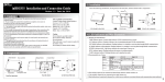
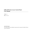
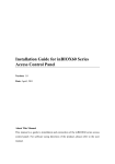
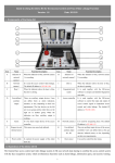
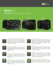
1.
Cautions
Please pay attention to the following items. Mis-operation may lead to equipment failure or personal injury.
1) Do not power on the system before the installation is complete. Do not install or repair while power is on.
2) All external devices must be grounded.
3) It is recommended that all wires run through PVC or galvanized conduit.
4) We recommend that the exposed part of all wires be shorter than 4 mm to avoid short circuiting or communication failure.
5) It is recommended that the card reader and the exit button be installed at a height of about 1.4-1.5m.
6) It is recommended to use separate power supplies for the control panel and the lock.
Description of normal working state:
Power on the system, the power indicator (red) is on constantly in normal working state, the run indicator (green)
is flashing, the communication indicator (yellow) is flashing when communicating.
2.
Components
Panel Box Appearance
Panel Box Inside
3.
Installation
After the following installation, fix the panel to the track first, and then install other components.
4.
LED Indicators and Wire Illustration
1) Meaning of LED indicators:
LINK indicator (green): Constant light indicates TCP/IP communication is normal.
ACT indicator (yellow): Flashing indicates data is transmitting through TCP/IP communication.
EXT RS485 indicator (yellow & green): Flashing indicates it is sending or receiving data through RS485 communication.
PC RS485 indicator (yellow & green): Flashing indicates it is sending or receiving data through RS485 communication.
RUN indicator (green): Flashing indicates the system is working normally.
CARD indicator (yellow): Flashing indicates a card is punched on reader.
Diagram on Panel 3
Ethernet Interface
DIP Switch
PC RS485 Interface
Auxiliary Output
Control Panel Power
5.
DIP Switch Settings
1) Switches 1-6 are used to set the control panel number in RS485 communication: It is adopted binary coding and little endian, the address number is set by placing these 6 switches as
shown in the figure below. Before setting the address, please keep the system powered off. Place the corresponding switches to the desired status, The
address number should not be repeated in the network.
For example: Set the device number as 39 (39=1+2+4+32), the switch’s status is 111001, that is set number 1, 2,
3 and 6 switches at “ON”.
2) Number 7 switch is used to restore the factory defaults: Switch it three times within 10 seconds and restart the device,
then all data will be cleared and the system restored to factory default settings.
3) Number 8 switch is used to set terminal resistance in RS485 communication: Switch it to “ON” status, which adds a terminal resistance of 120 ohm between 485+ and 485-.
6.
Lock Connection
1) The control panel provides lock control output interfaces. For NO lock, it is normal open when power is on, so
COM and NO terminals should be used. For NC lock, it is normal closed when power is on, so COM and NC
terminals should be used.
2) The control panel supports “dry mode” and “wet mode” by using the jumper. For “wet mode”, short terminals 2–3 and
4-5. The control panel and the lock use separate power supplies: One is connected with +12V and
201 Circle Drive N, Suite 116 Piscataway, NJ 08854 Tel: 732-412-6007 Fax: 732-412-6008
www.zkaccess.com
GND of POWER interface (for the control panel), the other is connected with V + and V- of LOCK interface
(for the lock). For detailed settings for “dry mode” and “wet mode”, please refer to the Installation Guide.
The factory default is dry mode.
3) For the Wiegand reader and the inBIO reader, the standard power supply is 12V/3A. So we do not recommend that the lock and the control panel share a common power supply.
If it is necessary to do so, we suggest using a larger one, such as 12V/5A. Not including the power
reserve, there are 2A current for the lock. For the common electrical lock (the stand by current is 300mA, the
maximum current is 500mA), the maximum connected locks is 4.
4) When the electrical lock is connected to the access control system, you need to parallel an Fr107 diode (included
in the package) to prevent self-induced EMF from affecting the system. Do not reverse the polarities.
Diagram on Panel 4
Insert a screw driver to the rectangular hole in the four corners of the panel back. Push it in until hearing the "click" sound. Then remove the case from the panel.
The following is “wet mode” lock connection with external power supply.
7.
485 Reader (inBIO Reader) Connection
The control panel supports inBIO biometric verification reader and Wiegand reader. All inBIO reader operations are execute from the control panel
including storage, verification, etc. Re-registering fingerprints is not required when replacing the reader.
Make the biometric reader connection.
inBIO reader connection: First of all, set the 485 address (device number) of the reader by software, DIP switch or keypad.
Readers 1 and 2 (the odd number is for the entry reader and the even number is for the exit reader) are for door number 1. And the
485 address is 1, 2, as in the figure below. For more information, please refer to the software user manual.
In the inBIO reader connection, a single EXT485 interface can supply 500mA (12V) current maximum. So the entire current
consumption should be less than this max value when the reader shares power with the panel.
For example, when you use the F11 reader (the standby current is less than 100mA, the max current is less than 120mA)
for the inBIO reader connection, the max number is 4 readers. For this type of panel, 2 readers can be connected at most. For
some of the devices with much greater consumption, we suggest using separate power supplies to ensure steady operation.
8.
Equipment Communication
The PC software can communicate with the panel according to the communication protocols (RS485 and TCP/IP) for data exchange and remote management. The communication cable
should be as far away from high-voltage lines as possible. Do not keep the communication cable parallel to power cords or bind them together.
1.
TCP/IP Communication
#1 Control Panel
#2 Control Panel
#8 Control Panel
2.
RS485 Communication
#1 Control Panel
#2 Control Panel
#8 Control Panel
1) Internationally accepted RVVP (shielded twisted-pair) wires should be used for communication to effectively avoid interference. RS485 communication wires should be
connected by means of bus cascade connection.
2) It is recommended that the RS485 bus should be less than 600 meters to help aid communication stability.
3) One RS485 bus may hold 63 control panels, but it is not recommended to connect with less than 32 access control panels.
4) For the inBIO reader connection, if the reader and the control panel use the same power, it is recommended that the wire be less than 100 meters. If greater length is required,
please use a separate power supply.
5) To enhance the stability of communication when the wire is longer than 300 meters, it is necessary to keep the number 8 switch of the first and last control panel at “ON”
status. That adds the RS485 terminal resistance (120 ohm) of the two devices to the system. As shown in the figure above, turn number 8 of the DIP switches of the #1 and #8 at
"ON” status.
201 Circle Drive N, Suite 116 Piscataway, NJ 08854 Tel: 732-412-6007 Fax: 732-412-6008
www.zkaccess.com