1
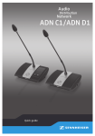
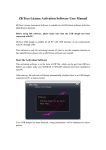
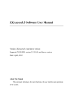
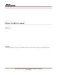
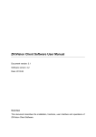
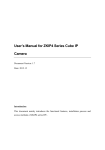
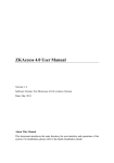
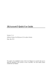
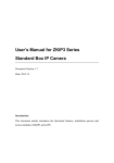
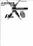
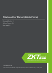
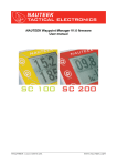
Guide to Using the Demo Kit for the Access Control and Face Video Linkage Function Version: 1.6 Date: 2013.03 I. Components of the Demo Kit H A I B J C D L E M K1 K1 K2 K2 F G K N Icon Name Function Description Icon Name Function Description A Indicator of When this indicator is blue, network camera H Indicator of When this indicator is blue, network camera network 1 is recording. network camera 2 2 is recording. camera 1 B C Network It is used for access control video linkage. camera 1 The default IP address is 192.168.1.88. Door 1 I Door 2 When the indicator above the door is blue, J Fingerprint/card It is used together with the ZKAccess reader software to compare and identify fingerprints the door is opening. When the indicator above the door is blue, the door is closing. and cards. D User-defined These are auxiliary output devices. Users L Access controller It is used together with the ZKAccess auxiliary can define them as alarm indicators, software to control the input and output of output monitors, or else, depending on their own access control signals to implement access requirements. The four devices on the left control and video linkage. The default IP are in one group and the other three on the address is 192.168.1.201. right are in another group. When the indicators are blue, auxiliary output is working. E Alarm It is the alarm output device of the access M Network camera 2 controller. F Request-to-exit This sensor can sense body infrared. It is used for recognizing faces. The default IP address is 192.168.1.87. K infrared sensor User-defined They are auxiliary input devices of the access auxiliary input controller. Users can define them as the gas K1, K2 detector, infrared sensor, or else, depending on their own requirements. G Power switch It controls the power supply of the entire N Door sensor It is used to control the door status. demo kit. II. Illustration of the Demo kit Kit The featured face access control and video linkage system of ZK uses network data sharing to combine the access control system with the face recognition system, which revolutionizes functions such as alarm linkage, information query, and security warning, 1 and strengthens access security. You can use this demo kit to demonstrate the access control and video linkage function and face access control and video linkage function. Auxiliary input, such as the smoke detector Door sensor Fingerprint reader Requestto-exit sensor Switch (in the demo kit) C3 access controller Auxiliary output, such as alarm indicators Alarm Door Network camera 1 Network camera 2 Network port (on the side of the demo kit) Storage battery of thePC Self-supplied PC ZKAccess ZKiVision III. System Configuration 1 Notes Use a power cable to connect a 220 V power supply to the power port on the side of the demo kit, and then turn on the power switch. If all indicators are steadily red for three seconds, the power supply is normal. If an indicator is blue, the corresponding device is working properly. When an alarm is triggered, the alarm indicator blinks red. After 20 seconds, the alarm will be automatically disabled. When the demo kit leaves the factory, the magnet of the door sensor is placed against the support of the demo kit. When the demo kit leaves the factory, network camera 2 (used for face recognition) is placed under the baffle. To demonstrate face recognition, remove the camera from the baffle and adjust its orientation. When the demo kit leaves the factory, it contains a registered card, which can be used to demonstrate access control and video linkage. If you want to add new users and configure related parameters, see step 2. Otherwise, see step 3. The access controller, network cameras, and other components have formed a local area network (LAN) through the switch in the demo kit. Use a network cable to connect your PC to the network port on the side of the kit to add your PC to this LAN.(Note: Set the IP addresses of your PC, the access controller, and the network cameras to ensure that they are on the same network segment. You are advised to set the IP address of your PC to 192.168.1.XX because the default IP addresses of the access controller and network cameras are all on this network segment.) 2 Installing ZKAccess3.5 Software and Configuring the Access Controller 2.1 Install ZKAccess3.5 on your PC from the installation CD-ROM. Note that the installation directory cannot contain Chinese characters. After the installation is completed, you need to restart the system. 2.2 Double-click the ZKAccess3.5 Security System icon to start the software. By default, the system has a superuser admin with the password of admin. 2.3 Select Search for Access Controller in the left pane of the main page, and click Search in the displayed window. Then add the access controller displayed in the search output to the software. (Note: On the pop-up "Add Device" interface, please uncheck “Clear Data in the Device when Adding”.) 2 2.4 Choose Personnel->Add to add personnel and register their fingerprints and card information. (1) Register fingerprints: Connect a fingerprint device (you need to prepare one) to your PC, click Register in Register Fingerprints, and choose to register common fingerprints or duress fingerprints in the displayed window. (2) Register cards: Click Access Control Card, and swipe cards to be registered on the fingerprint / card reader. 2.5 Add new users to groups: Choose Access Control Group->New, move the selected doors and personnel from the left to the right, specify related parameters, and click OK to synchronize the setting to the device. (Note: After the synchronization is completed, if swiping cards is successful but fingerprint scan is unavailable, open the Device page and choose Synchronize All Data to Device.) 2.6 To demonstrate the states of Door Opened, Door Accidentally Opened, Opening Door Timeout, and Door Closed, you need to add the Usually Closed state to the access controller software. In the left pane, choose Door Setting, double-click Door Sensor Type in the displayed window, set Door Sensor Type to Usually Closed, and click Save to synchronize the setting to the device. 3 Installing the ZKiVision Software and Configuring the Face Recognition Function and Access Control and Face Video Linkage 3.1 On your PC, install the video management software ZKiVision from the installation CD-ROM. 3.2 Double-click the ZKiVision icon to start the software. By default, the system has a superuser Admin with the password of 123456. 3.3 Open the Setting-Device Search page, search for cameras, add them to the system, and set partitions. 3.4 Open the Setting-Access Control System Management page, manually add an access controller (the default access control port is 4370) to the system, and link the cameras with the access controller. 3 3.5 Open the Preview page, right-click the picture of network camera 2, choose Enable Face Recognition, and manually register or import pictures of users' faces. 3.6 Open the Setting-> Alarm Setting page, and double-click the camera channel. After a connection is set up, select alarm signal terminals in Input Signal List, select the linked motions (single or multiple) in Linkage Action List, and click Save to save the alarm linkage setting. If you need to set the linkage period, select Enable Input Signal Setting and set the time period before saving the setting. 3.7 Open the Preview page, right-click the device tree, and click Alarming to configure surveillance. If the system detects an access control alarm or face signal, the system will react according to the alarm linkage setting (for example, start recording, display a video window, or open doors). Note: 1. For details about the configuration of the access controller, see the ZKAccess User Manual. 2. For details about the configuration of the face recognition function and face access control and video linkage function, see the ZKiVision User Manual. IV. Demonstration of the Access Control and Face Video Linkage Function Use a power cable to connect a 220 V power supply to the power port on the side of the demo kit. Then turn on the power switch. Use a network cable to connect your PC to the network port on the side of the demo kit. Install the ZKAccess software on your PC, configure the access controller, install the ZKiVision, register users' faces, and link the access controller with to cameras. For details, see System Configuration. The following describes the demonstration of access control and video linkage and face access control and video linkage: 4 1 Demonstrating Access Control and Video Linkage (Access Control Signals: Work Attendance, Request-to-Exit, Duress Alarm, Fingerprint (Unregistered), Door Accidentally Opened, Access Control Auxiliary Input) 1.1 Open the Setting-Alarm Setting page of the ZKiVision software. 1.2 Setting: Select Work Attendance in Input Signal List, and select Linkage Recording and Open Door in Linkage Motion List. Demonstration: Verify registered fingerprints or cards using the reader. Network camera 1 will start recording and door 2 will open. 1.3 Setting: Select Exit Switch in Input Signal List, and select Linkage Recording and Open Door in Linkage Motion List. Demonstration: Place your hand over the request-to-exit infrared sensor. Network camera 1 will start recording and door 2 will open. 1.4 Setting: Select Duress Alarm in Input Signal List, and select Linkage Recording and Open Door in Linkage Motion List. Demonstration: Verify registered duress fingerprints using the reader. Network camera 1 will start recording and door 2 will open. 1.5 Setting: Select Fingerprint in Input Signal List, and select Linkage Recording, Alarm Buzzer, and Open Door in Linkage Motion List. Demonstration: Verify unregistered fingerprints or cards using the reader. Network camera 1 will start recording, the alarm buzzer will ring, and door 2 will open. 1.6 Setting: Select Door Accidentally Opened in Input Signal List, and select Linkage Recording and Alarm Buzzer in Linkage Motion List. Demonstration: Displace the magnet of the door sensor without swiping cards or verifying fingerprints. Network camera 1 will start recording, the alarm buzzer will ring, and door 2 will open. Place the magnet back. The recording will end and the alarm buzzer will stop ringing. 1.7 Setting: Select Auxiliary Input in Input Signal List, and select Display Video Window, Linkage Recording, Alarm Buzzer, and Auxiliary Output in Linkage Motion List. Demonstration: Press the K1 button (auxiliary input: for example, the infrared detector detects the entry of a person). Network camera 1 will display a video window and start recording, the alarm buzzer will ring, and the auxiliary output indicator is blinking blue (auxiliary output: for example, the alarm indicator is blinking). 2 Demonstrating Face Access Control and Video Linkage (Camera Signals: Common Faces Detected, Blacklisted Faces Detected) 2.1 Open the Setting-Alarm Setting page of the ZKiVision software. 5 2.2 Setting: Select Common Face Detected in Input Signal List, and select Linkage Recording and Open Door in Linkage Motion List. Demonstration: Stand before network camera 2. If the system recognizes you as a common user through face recognition, network camera 2 will start recording and door 2 will open. 2.3 Setting: Click Blacklisted Face Detected in Input Signal List, and select Display Video Window, Linkage Recording, Alarm Bell, and Auxiliary Output in Linkage Motion List. Demonstration: Stand before network camera 2. If the system recognizes you as a blacklisted user through face recognition, network camera 2 will display a video window and start recording, the alarm buzzer rings, and the auxiliary output indicator lights on in blue (auxiliary output: for example, the alarm indicator is blinking). 3 After the demonstration, you can open the Event Query page of the ZKiVision software to search for access control/face event logs and play back its related record video. 6