1
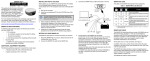
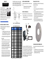
SMART-AG™
QUICK START GUIDE
The SMART-AG cable provides a means of supplying
power from a battery while operating in the field. The
bare wires (red for positive and black for negative) can
then be tied to a battery supply capable of at least 5 W.
This guide provides the basic
information you need to set up and begin
using your new SMART-AG, a combined
L1 GNSS receiver and antenna with
Emulated Radar (ER) output. For more
detailed information on the installation
and operation of your receiver, please
refer to the OEMV user manuals. The manuals and their latest
updates may be found on our website at:
ADDITIONAL EQUIPMENT REQUIRED
INSTALLING THE PC UTILITIES
The additional equipment listed below is required for a basic
setup:
• A Windows-based PC with an RS-232 DB-9 port
• A battery connection (+8 to +36 V DC)
Once the SMART-AG is connected to the PC and power supply,
install NovAtel’s PC Utilities.
SETTING UP YOUR SMART-AG
3. Select Install the OEMV PC Utilities from the window that is
automatically displayed. If the window does not
automatically open when the CD is inserted, select Run from
the Start menu and select the Browse button to locate
Setup.exe on the CD drive.
Complete the steps below to connect and power your receiver.
1. Mount the SMART-AG on a secure, stable structure with an
unobstructed view of the sky.
2. Connect the SMART-AG to a DB-9 serial port on the PC.
http://www.novatel.com/support/docupdates.htm
SMART-AG DEVELOPMENT KIT CONTENTS
Accompanying this quick start guide, the following are also
provided with your SMART-AG:
•
1 CD containing:
•
An installation program for NovAtel’s Control and
Display Unit (CDU) graphical user interface software
•
Product documentation, including user manuals
•
1 User Manual postcard for requesting printed manuals
•
Mounting Plate
•
1 SMART-AG cable for power and communications:
The cable has two DB-9 connectors, see Figure 1. One
can accommodate a PC/laptop serial (RS-232)
communication port and the other can connect to a
modem or radio transmitter to receive differential
corrections (refer to your user-supplied modem or radio
transmitter information for its connectors).
At the other end is a 14-pin connector, see Figure 1. In
addition, there are a number of bare wires where the
outer insulation is cut away but the wires beneath are
intact. See Table 1 below for their pinouts. This cable is
RoHS compliant and its part number is 01018256.
Figure 1: 14-pin and DB-9 Pin Numbers
User Supplied
5A Fast Blow
Fuse
Table 1: SMART-AG Cable Wire Colors
Wire Color
Signal Name
Red
White
Red
White
Black
Black
White-Black
White-Black
White-Black
Yellow
Green
Black
Blue
White
Orange
Red
COM1_TXD
COM1_RXD
COM2_TXD
COM2_RXD
COM1 GND
COM2 GND
MMI GND
ER GND
PPS GND
CANI+
CANINO CONNECT
PWR RET (GND)
EMD RADAR OUT
MAN MARK IN
PPS
NO CONNECT
PWR INPUT
14-pin DB-9 DB-9
(J1)
(J2)
(J3)
1
2
3
4
5
5
5
5
5
6
7
8
9
10
11
12
13
14
+
1. Start up the PC.
2. Insert the accompanying CD into the CD-ROM drive of the
computer.
4. Install the PC Utilities by advancing through the steps
provided in the NovAtel GPS PC Utilities setup program.
-
Label
Emulated Radar
2
3
MKI
2
3
PPS
COM
CAN
5
Note: Minimum Conductor size for all
wiring is 0.5 mm/20 AWG
5
MMI GND
ER GND
PPS GND
CANI+
CANIBATTER_OUT
MMI
PPS
BATT+
COM
ESTABLISHING RECEIVER COMMUNICATION
3. Connect power to the SMART-AG. The cable’s red wire
(connector pin 14) is to be connected to the positive side of a
12 or 24V vehicular power circuit (or equivalent) protected
by a 5A fast blow fuse (user supplied). The cable’s black
wire (connector pin 9) is to be connected to the negative side
of the power circuit. If a SMART-AG cable (NovAtel part
number 01018256) is not used, a minimum wire size of
0.5 mm/ 20AWG must be used.
To open a serial port to communicate with the receiver, complete
the following.
1. Launch CDU from the Start menu folder specified during the
installation process. The default location is Start | Programs |
NovAtel OEMV | OEMV PC Software.
2. Select Open.... from the Device menu.
6. Select 115200 from the Baud Rate list.
SMART-AG LEDS
7. Uncheck the Hardware Handshaking checkbox.
The LEDs on the SMART-AG represent these categories:
8. Select OK to save the new device settings.
9. Select the new configuration from the Available device
configs area of the Open dialog.
3. Select the New... button in the Open dialog box. The Options
| Configuration dialog opens.
4. Use the
button at the top of the configurations selection
box to add a new configuration. To delete a configuration,
select it from the list and click on the
button. To duplicate
an existing configuration, click on the
button. You can
select any name in the list and edit it to change it.
SMARTAG
5. Select Serial from the Type list and select the PC/laptop
port, that the DL-V3 is connected to, from the Port list.
10. Select the Open button to open SMART-AG
communications.
As CDU establishes the communication session with the
receiver, it displays a progress box. Once CDU is connected,
the progress box disappears and several windows open,
including the Console window. CDU is now ready for use to
view status information, enter commands, or log data.
USING CDU
CDU provides access to key information about your receiver and
its position. The information is displayed in windows accessed
from the View menu. For example, select Position Window from
the View menu to display the position solution of the receiver. To
show details of the GNSS and geostationary (SBAS) satellites
being tracked, select the a Tracking Status Window from the
View menu. Select Help from the main menu for more details on
CDU, its windows and features.
DETERMINING WHEN THE POSITION IS VALID
When the receiver has a valid position, the Solution Status field
in CDU’s Position window shows Computed.
ENTERING COMMANDS
LOGGING DATA
ENABLING SBAS POSITIONING
The SMART-AG uses a comprehensive command interface.
Commands can be sent to the receiver using the Console
window in CDU, which is opened from the View menu. Enter
commands in the text box at the bottom of the Console window.
An extensive collection of logs has been created to capture the
data your SMART-AG receives and processes. These logs can
be directed to a SMART-AG port (COM1, COM2 or USB) and
can be automatically generated when new or changed data
becomes available or at regular intervals. The available logs are
listed in the OEMV Family Quick Reference Guide.
To enable SBAS positioning, enter the following command:
To log data, use the LOG command. For example, to log the
pseudorange position to COM 2 every 30 seconds, enter the
following:
pdpmode relative auto
The following information is important when entering commands:
•
Commands can be entered in three formats:
• ASCII (log bestposa)
•
Abbreviated ASCII (log bestpos)
•
Binary (log bestposb).
Abbreviated ASCII is the best format to use when you
wish to work with the receiver directly. For data
collection, use ASCII or Binary.
•
Press Enter to send the command string to the receiver.
•
The commands are not case sensitive.
The OEMV Family Quick Reference Guide provided with the
receiver lists the available commands and the parameters they
use for the Abbreviated ASCII format.
LOG COM2 PSRPOS ONTIME 30
Logs can be generated in one of three formats: ASCII,
Abbreviated ASCII, or Binary. Refer to the OEMV Family
Firmware Reference Manual (OM-20000094) for information on
the LOG command, specifying the output format, and the
detailed contents of each log.
If you prefer, CDU provides a graphical interface for configuring
data logging. Select Logging Control Window from the Tools
menu. In the Logging Control window, you can select which logs
to capture and choose to which ports to send the data. In
addition, you can specify a file in which to save the data.
sbascontrol enable
To enable GL1DE, enter the following commands:
pdpfilter enable
USING THE CAN BUS
A CAN Bus is a serial bus that provides services for processes,
data and network management. There is CAN Bus capability
through the SMART-AG cable, see Table 1 on Page 1. CAN Bus
functionality is controlled through NovAtel’s optional API
software available through Customer Service. The API header
file (*.h), in the API folder after installation, includes
documentation on using the CAN Bus.
NEMA 2000 is a CAN standard created by the National Marine
Electronics Association and designed to support networking in
marine applications. It functions over a longer physical distance,
and supports more physical nodes than ISO 11783. The
relationship between NMEA2000 and SAE J1939 is that J1939
is the standard,while the NMEA 2000 group has added some
new messages (called PGNs or Parameter Group Numbers)
and added a new, additional transport protocol called
FastPacket. NMEA2000 compliant, for all intents and purposes,
means J1939 compliant plus support for new NMEA2000
messages. In other word, one cannot have NMEA2000 without
J1939 support as well. J1939 is additionally “harmonized” with
ISO 11783, a standard for the agriculture industry.
The CAN module is generally not user-interactive. It is activated
when a SETCANNAME command is entered, and after a
SAVECONFIG, the CAN module is activated immediately on all
subsequent start-ups. The module supports NMEA2000
Parameter Group Message (PGN): PGN 129029
GNSSPositionData, PGN 129025 GNSSPositionRapidUpdate,
and PGN 129026 COGandSOGRapidUpdate.
EMULATED RADAR (ER)
The SMART-AG outputs an emulated RADAR signal. The
enclosure outputs ER via the bare wires labeled ER GND and
ER_OUT on the SMART-AG cable. See Table 1 on Page 1 for
the pin-out details of this cable. Also see the RADARCFG
command on Page 63 of the SMART-AG User Manual.
The ER outputs a logic high of 6.3 V minimum and logic low of
1.5 V maximum with a rise and fall time of less than 1 ms. Its
output references battery GND when output is logic low and
provides logic low output until its speed is greater than 1 km/Hr.
It provides an output frequency that represents 26.11 Hz/km/Hr
with an effective range from 1 km/Hr to 55 km/Hr and uses 2D
velocity for near-horizontal applications.
QUESTIONS OR COMMENTS
If you have any questions or comments regarding your
SMART-AG please contact NovAtel using one of these methods:
Email: [email protected]
Web:
www.novatel.com
Phone: 1-800-NOVATEL (U.S. & Canada)
403-295-4900 (International)
Quick Start Guide:
SMART-AG:
© Copyright 2008 NovAtel Inc. All rights reserved.
Printed in Canada on recycled paper. Recyclable.
Unpublished rights reserved under international copyright laws.
GM-14915085
Rev 2
2008/12/17