1
User’s Manual
MSE PSE-SW3 series
*PD Port Wiring
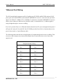
Port 1 & 2 provide PoE inject function with maximum 35W ability to power up the powered device
use the straight-through or cross-over Ethernet cable.
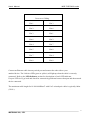
The PoE switch follows the IEEE802.3af Alternative B mode connector assignment. The following
table shows pin assignment of alternative A and B for the Power Source Equipment.
Conductor
Alternative A
Alternative A
Alternative B
(MDI-X)
(MDI)
(All)
1
Negative Vport
Positive Vport
2
Negative Vport
Positive Vport
3
Positive Vport
Negative port
4
Positive Vport
5
Positive Vport
6
Positive Vport
NegativenVport
7
Negative Vport
8
Negative Vport
Be sure the twisted pair cable is bound with the standard RJ-45 pin, especially the pin 4, 5, 7 and 8.
If the RJ-45 is bound with the wrong pin number, PoE switch will not recognize the PD and won’t
deliver DC power to PD. The yellow PoE LED will light up when the cable is correctly connected.
Refer to the LED Indicator section for descriptions of each LED indicator. If a port LED is off, go
back and check for connectivity problems between that port and the network device connected.
10
MSTRONIC CO., LTD.