1
User’s Manual
MSE PSE-SW3 series
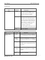
*PoE LED (the left indicator on RJ45)
Yellow
P1,P2
A valid Powered Device (PD) is detected
and delivering power on this port.
PoE
Off
No PD is detected on this port.
Yellow
Powered via all 4 data pairs.
Yellow
Powered via 2 data pairs. (1,2,3,6 or 4,5,7,8
Blanking
are all acceptable).
Off
No power is detected on this port.
UP LINK
PoE
*Power wiring
The PoE switch family includes 3 models, be used for 2 different ranges of input voltage as,
full range voltage (12 to 57VDC)
(P/N: PSE-SW3G11CN)
48VDC typical
(P/N: PSE-SW3G44DN & PSE-SW3G42CN)
(42 to 57VDC)
48VDC typical switches allow powered by another PoE source (42~57VDC) on port UP LINK.
For PoE operation, make sure your power supply may offer at least 40W for 2x 802.3af PoE port, or
80W for 4x 802.3at PoE port.
If powered on rear terminal, please make sure the input current don’t over 10A, if powered on port
UP LINK, make sure the input current don’t over 2Amp.
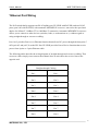
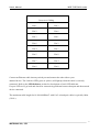
The port 1&2 will deliver DC power over the Ethernet cable, the connection as:
* Data pair A on line 1 and 2
* Data pair B on line 3 and 6
* Data pair C plus V+ on line 4 and 5
* Data pair D plus V- on line 7 and 8
5
MSTRONIC CO., LTD.