1
11
known mass, called a proof mass. The most common way to measure this force
is by measuring the dislocation of the proof mass. [12]
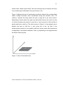
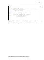
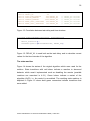
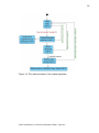
Figure 1 displays the axes of acceleration sensitivity whereat the corresponding
output voltage increases when accelerated along the sensitive axis. For
instance, consider the case where the part is lying flat on an even surface.
Depending on which side of the part is up and which is down, the z-axis is in the
±1-g field of gravity and reads ±1 g and the x- and y-axis are in the 0-g field of
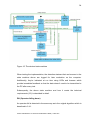
gravity and hence read 0 g. This can be seen in Figure 2. It also shows how to
position the part so that the x- and y-axis are in the 1-g field. If the
accelerometer remains in one position and isn’t moved, each axis experiences
a magnitude of acceleration between 0 and 1 g depending on its alignment with
the earth’s field of gravity.
Figure 1: Axes of Acceleration [2]
TURKU UNIVERSITY OF APPLIED SCIENCES THESIS | Lukas Kern