1
PSI System Controls and Diagnostics
8 Installation
8.1 Mounting
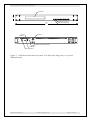
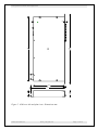
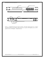
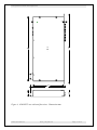
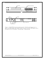
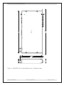
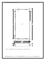
The A500 is intended for mounting in a 19” rack. It can be used free-standing on a table-top if
required.
The mounting position should allow sufficient access to connectors and cable bend radii. Leave
100mm clearance at either end for mating connectors and cable radii. The cooling fan must not
be obstructed.
8.2 Grounding and power supply
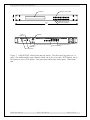
A secure connection should be made using a ring lug, from the M4 ground lug to local chassis
potential. +24 VDC power should be provided from a suitably-rated power supply with the
following minimum performance:
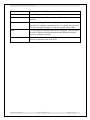
Output voltage
+24 +/- 0.5 VDC
Output current
500 mA minimum, 2000 mA maximum
Ripple and noise
< 100 mV pk-pk, 1 Hz to 1 MHz
Line regulation
< 240 mV
The A500 includes an internal automatically re-setting PTC fuse rated at 1.1 A. However the
external supply should in no circumstances be rated higher than the A500 connector limit of 5 A,
and a maximum of 2.0 A is recommended.
A500 User Manual
A500_UM_090115
Page 21 of 61