1
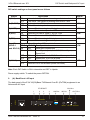
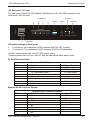
VCL-4 Ethernet over 1E1
3.
Bottom Panel
Bottom Panel:
The Bottom panel of the E1/4*10(100)Base-T 4Ethernet over E1 (IPoTDM) equipment is as
follows.
Time-slot configuration of E1 port: For E1 time-slot configuration, the DIP Switch settings on
the bottom panel are as follows:
Working Mode
Unframed
Framed (CCS/PCM-31)
Multi-Framed (CAS/PCM-30 )
Switch Setting
All switches are set to OFF
S0 set to OFF, and the occupied time slots to ON
All switches S0~S31 set to ON but S16 is set to OFF
The time-slot DIP switches located at the bottom of the equipment marked with TS0~TS31 bits
corresponding to 0~31 time-slots of E1 channel.
Note: It is recommended to set the TS0 DIP switch OFF.
Example 1: If you wish to use only first 5 time-slots then you need to set the S0 time-slots to OFF
and switch S1 to S5 to ON and time-slot S16 will be set to ON.
Example 2: If you wish to carry first 8 time-slots on 512Kbps, then you need to set the S0 time-slot
OFF and switch S1 to S8 to ON (i.e. since each time-slot consumes 64Kbps, so 8 time-slots will
consume 8 x 64Kbps = 512Kbps) and time-slot S16 will be set to ON.
Example 3: If you wish to carry 20 time-slots on 1.28Mbps (64Kbps x 20) then you need to set time
slot S0 OFF and S1 to S21 time-slots to ON. Please remember that the time-slot S16 will be used
as signaling time-slot.
Orion Telecom Networks Inc. - 2006-10
13