1
Bachelor’s Thesis
HORN - Hank and OpenDRIVE
Road Networks:
An editor for creating HANK
scenarios while working with
OpenDRIVE
by
Cim Öberg
LIU-IDA/LITH-EX-G–12/011–SE
September 24, 2012
Linköping university
Department of Computer and Information Science
Final thesis
HORN - Hank and OpenDRIVE
Road Networks:
An editor for creating HANK
scenarios while working with
OpenDRIVE
by
Cim Öberg
LIU-IDA/LITH-EX-G–12/011–SE
September 24, 2012
Supervisor:
Rita Kovordanyi
Examiner:
Rita Kovordanyi
Abstract
HORN is a solution to the problem of how to implement scenarios in a more
efficient way than was previously possible allowing researchers who wish to
create scenarios for HANK the ability to quicker implement larger scenarios
than was previously possible. OpenDRIVE is an open standard for road
networks that is believed to be the way forward and Horn is an attempt
at unifying OpenDRIVE scenarios with HANK - the driving simulator currently in use at Linköpings Universitet, thus futureproofing all work done
to implement scenarios. Before HORN HANK scenarios were laboriously
constructed with a really bad program or by hand and HORN tries to make
the process far less painful. This thesis describes how to work with the
Road Network Editor program HORN (”Hank and OpenDRIVE Road Networks”) that was developed for working with HANK’s scenarios as well as
my experience implementing it and some of the fascinating rules for how to
draw some exotic two dimensional geometries I found out about as I worked
on HORN.
iii
Acknowledgements
This work would not have been possible to accomplish without the help of
my parents and my beloved Ingrid and my thanks go out to them for helping
me and standing by me through it all. My thanks also go out to my advisor,
Rita Kovordanyi for allowing me to take the time needed to finish everything
and giving me goals to work towards and my opponent Jens Christensen who
helped me improve this document in many small ways. I would also like to
thank my study councilor Siv Söderlund for helping me to get through the
education.
v
Contents
1 Introduction
1.1 Introduction . . . . .
1.1.1 Background .
1.1.2 Similar work
1.1.3 Purpose . . .
1.1.4 Method . . .
1.1.5 Boundaries .
1.1.6 Structure . .
.
.
.
.
.
.
.
.
.
.
.
.
.
.
.
.
.
.
.
.
.
.
.
.
.
.
.
.
.
.
.
.
.
.
.
.
.
.
.
.
.
.
.
.
.
.
.
.
.
.
.
.
.
.
.
.
.
.
.
.
.
.
.
.
.
.
.
.
.
.
.
.
.
.
.
.
.
.
.
.
.
.
.
.
.
.
.
.
.
.
.
.
.
.
.
.
.
.
.
.
.
.
.
.
.
.
.
.
.
.
.
.
1
1
1
2
2
3
3
3
2 Body
2.1 Background . . . . . . . . . . . . .
2.1.1 OpenDRIVE . . . . . . . .
2.1.2 HANK . . . . . . . . . . . .
2.1.3 Road networks . . . . . . .
2.1.4 Road network editors . . .
2.2 Previous work . . . . . . . . . . . .
2.2.1 ROD . . . . . . . . . . . . .
2.2.2 VUEMS . . . . . . . . . . .
2.2.3 CUBE . . . . . . . . . . . .
2.2.4 Emme . . . . . . . . . . . .
2.3 HORN . . . . . . . . . . . . . . . .
2.3.1 Basic terminology . . . . .
2.3.2 XML editor . . . . . . . . .
2.3.3 Controllers . . . . . . . . .
2.3.4 Roads . . . . . . . . . . . .
2.3.5 Junctions . . . . . . . . . .
2.3.6 Global objects . . . . . . .
2.3.7 Hank intersection templates
2.3.8 Library . . . . . . . . . . .
2.3.9 Road map view . . . . . . .
2.4 Geometrical figures in HORN . . .
2.4.1 Geometries . . . . . . . . .
2.4.2 Curvature . . . . . . . . . .
2.4.3 Line . . . . . . . . . . . . .
.
.
.
.
.
.
.
.
.
.
.
.
.
.
.
.
.
.
.
.
.
.
.
.
.
.
.
.
.
.
.
.
.
.
.
.
.
.
.
.
.
.
.
.
.
.
.
.
.
.
.
.
.
.
.
.
.
.
.
.
.
.
.
.
.
.
.
.
.
.
.
.
.
.
.
.
.
.
.
.
.
.
.
.
.
.
.
.
.
.
.
.
.
.
.
.
.
.
.
.
.
.
.
.
.
.
.
.
.
.
.
.
.
.
.
.
.
.
.
.
.
.
.
.
.
.
.
.
.
.
.
.
.
.
.
.
.
.
.
.
.
.
.
.
.
.
.
.
.
.
.
.
.
.
.
.
.
.
.
.
.
.
.
.
.
.
.
.
.
.
.
.
.
.
.
.
.
.
.
.
.
.
.
.
.
.
.
.
.
.
.
.
.
.
.
.
.
.
.
.
.
.
.
.
.
.
.
.
.
.
.
.
.
.
.
.
.
.
.
.
.
.
.
.
.
.
.
.
.
.
.
.
.
.
.
.
.
.
.
.
.
.
.
.
.
.
.
.
.
.
.
.
.
.
.
.
.
.
.
.
.
.
.
.
.
.
.
.
.
.
.
.
.
.
.
.
.
.
.
.
.
.
.
.
.
.
.
.
.
.
.
.
.
.
.
.
.
.
.
.
.
.
.
.
.
.
.
.
.
.
.
.
.
.
.
.
.
.
.
.
.
.
.
.
.
.
.
.
.
.
.
.
.
.
.
.
.
.
.
.
.
.
.
.
.
.
.
.
.
.
.
.
.
.
.
.
.
.
.
.
4
4
4
5
6
6
7
7
8
8
8
9
9
9
11
11
17
17
18
19
20
21
21
22
22
.
.
.
.
.
.
.
.
.
.
.
.
.
.
.
.
.
.
.
.
.
.
.
.
.
.
.
.
.
.
.
.
.
.
.
vii
.
.
.
.
.
.
.
.
.
.
.
.
.
.
CONTENTS
2.4.4
2.4.5
2.4.6
2.4.7
2.4.8
CONTENTS
Arc . . . .
Spiral . . .
Polynome .
Spline . . .
Hank Spiral
.
.
.
.
.
.
.
.
.
.
.
.
.
.
.
.
.
.
.
.
.
.
.
.
.
.
.
.
.
.
.
.
.
.
.
.
.
.
.
.
.
.
.
.
.
.
.
.
.
.
.
.
.
.
.
.
.
.
.
.
.
.
.
.
.
.
.
.
.
.
.
.
.
.
.
.
.
.
.
.
.
.
.
.
.
.
.
.
.
.
.
.
.
.
.
.
.
.
.
.
.
.
.
.
.
.
.
.
.
.
.
.
.
.
.
.
.
.
.
.
23
24
25
26
28
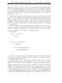
3 Closing
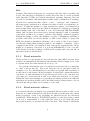
3.1 The development process . . .
3.2 Conclusion . . . . . . . . . . .
3.3 Future work, problem areas . .
3.3.1 General improvements .
3.3.2 Usability improvements
3.3.3 Editing improvements .
3.3.4 3d modelling . . . . . .
.
.
.
.
.
.
.
.
.
.
.
.
.
.
.
.
.
.
.
.
.
.
.
.
.
.
.
.
.
.
.
.
.
.
.
.
.
.
.
.
.
.
.
.
.
.
.
.
.
.
.
.
.
.
.
.
.
.
.
.
.
.
.
.
.
.
.
.
.
.
.
.
.
.
.
.
.
.
.
.
.
.
.
.
.
.
.
.
.
.
.
.
.
.
.
.
.
.
.
.
.
.
.
.
.
.
.
.
.
.
.
.
.
.
.
.
.
.
.
32
32
38
39
39
40
40
40
4 Bibliography
42
5 Appendix
45
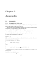
5.1 Appendix . . . . . . . . . . . . . . . . . . . . . . . . . . . . . 45
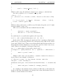
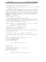
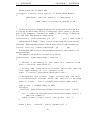
5.1.1 Examples of SDL code . . . . . . . . . . . . . . . . . . 45
viii
Chapter 1
Introduction
1.1
1.1.1
Introduction
Background
A simulator is a program that attempts to recreate a part of reality in as
much detail as possible, thus making the experience in the simulator as
authentic as it can be. A driving simulator in particular is concerned with
recreating the experience of driving a car that handles like a real car for
example in a race track or in traffic.
Driving simulators have many uses, for example practising driving in
general, practising various scenarios, or in a university environment - seeing
how people react to various traffic or driving situations as part of behavioral
research or to see how people react to a particular road design. To this
end there needs to be a simulator that allows scenarios and situations to
be created. There are many driving simulators, and a particular driving
simulator used at University of Linköping is HANK.
HANK was created at University of Iowa to help them in their work with
traffic research, they were especially interested in setting up experiments to
see how participants would react to various situations. HANK uses two
domain specific languages called EDF (”Environment Description Framework”) and SDL (”Scenario Description Language”) to create the logical
structure of its world.
While EDF and EDL are both powerful it is both hard for the uninitiated to get started in part because there does not seem to be any official
documentation, and even with a teacher it can take a long time to get up
to speed. It also gets tiresome to essentially through trial and error enter
programming code and firing up the simulator until one obtains the desired
results. There should be a better way to set up the simulation environment,
and that is where HORN comes in.
1
1.1. INTRODUCTION
1.1.2
CHAPTER 1. INTRODUCTION
Similar work
There does not appear to have been anything made before that does what
HORN does. HORN is unique in converting OpenDRIVE files to something
that Hank can run.
Before HORN there was a commercial editor available that uses it’s
own proprietary format to export to Hank. It was hard to use and required
much training to laboriously construct road networks through a horrible user
interface. It’s users hate it and feel that anything would be an improvement.
I was unfortunately only shown it once and did not catch the name, but
HORN will be replacing it.
I will be briefly discussing other road network editors that are in no way
related to Hank later in this document.
1.1.3
Purpose
The way things worked was unsatisfactory and I was asked to create a program that allows the user to create scenarios for HANK as well as look into
road networks in general.
By not having to work directly with EDF and SDL in a text editor and
just focusing on the data users can save much time and effort that would
otherwise be spent learning these domain specific languages and finding
syntax errors. Another advantage over having a well functioning editor over
editing text files is the instant feedback that becomes possible by having a
WYSIWYG (”What you see is what you get”) screen that shows how the
different elements of the road line up so it becomes easy to see that the
road elements are indeed connected. The goal of my project was originally
to make something that would let people use a graphical interface to create
HANK driving scenarios.
Another concern was portability as HANK is getting somewhat old and it
would be nice to be able to run scenarios on the road networks in a different
simulator with as little effort as possible.
OpenDRIVE is an open standard that is supported in for example SUMO[8]
and ROD[4]. There are many other road network standards (about one for
every simulator that has any reason to have road networks), but most of
them are proprietary, and the nice thing about OpenDrive is that it is in
fact open and should there be a need to make it work with a particular
simulator that at least uses a similar format importing scenarios should be
at worst a matter of writing another export functionality for that simulator,
similar to the exporter in HORN. Because of OpenDRIVE being the future
it seemed like an obvious choise we agreed to try to make the user do as
much work as possible in OpenDrive to make their scenarios future proof.
I chose to name the resulting program HORN (”Hank and OpenDRIVE
Road Networks”). HORN lets the user create scenarios in an extended
version of OpenDRIVE. It is extended as HANK mixes data and behavior
in its files whereas OpenDRIVE is only concerned about data, and even
2
1.1. INTRODUCTION
CHAPTER 1. INTRODUCTION
though HORN is operating on OpenDRIVE data its primary function is as
a road network editor for HANK.
1.1.4
Method
The method I chose to implement this project was to do some light research
into road network editors and coding to the requirements document I was
given near the start of the project. I used an agile methodology where I
developed a feature at a time with a top-down design and verified that it was
working well and had not broken any other feature before moving on to the
development of the next feature, checking off features on the requirements
document as I got them done, and maintained a hierarchical todo list over
things that needed to be done to check off a requirement.
When the program was determined to be working satisfactorily I began
writing this thesis with the aim of providing a manual for HORN, and to
show my findings about road networks.
1.1.5
Boundaries
Unfortunately HANK has a number of undocumented binary file formats it
uses for various things, for example graphics. As they are undocumented
I have not been able to implement any support for them in HORN and
therefore creating a 3d model of the scenario is still something that needs
to be done separately.
1.1.6
Structure
This thesis seeks to describe HORN and act as a user manual as well as
describe my experiences implementing it and some of the fascinating rules
for how to draw some exotic two dimensional geometries I found out about
as I worked on HORN.
We will start by looking closer at the parts that
3
Chapter 2
Body
2.1
Background
2.1.1
OpenDRIVE
OpenDRIVE is an open standard for a file format describing a road network.
It is very detailed with a lot of relevant properties for various parts of a
road network and the details of individual roads. It focuses on being a data
description language and I feel it does so very well with a broad range of
data that can closely define the characteristics of a road network.
OpenDRIVE is based on XML with a root node called OpenDRIVE
which has child nodes like roads, crossings, and junctions. Most nodes have
both data and other nodes which in turn may contain further data and
nodes.
This imposes a tree structure on the data that makes it directly harmful
for moving various objects around as they are tied to their parents. For
example a road line is part of a lane which is part of the left lanes which is
part of the lanes which is part of the road which is part of the roads, but as
a road does not necessarily have any left lanes it is not clear what moving a
road line from road A to road B should actually do.
This limitation has somewhat limited the usability of HORN in that it
is very reliant on copying things back and forth between the library and the
editor rather than just moving physical things around (In the above example
it would be more intuitive to me to just place a road line where I want it
to be rather than positioning it in coordinates relative to the road inside a
lane. As a container format for a finished network it works very well, but it
is my personal opinion that it was a poor choise to work directly with the
format in hindsight.
Another issue with OpenDRIVE is that it is only a format for specifying
(in high detail) the layout of the road network. It does not contain anything
like scenario scripting or graphical information. I might come across as
4
2.1. BACKGROUND
CHAPTER 2. BODY
being critical of the standard, but I do think that it is very good at what
it does. However I feel that using OpenDRIVE has forced me to make
design decisions I am not comfortable with that have negatively impacted
the resulting program which could have been a better editor if it was allowed
to focus on doing a good job with HANK scenario creation.
As HORN is heavily centered on OpenDRIVE the standard is implicitly
described in the manual in the part about the XML editor a little bit ahead,
so I will not go into more detail here.
2.1.2
HANK
Hank [1] consists of a simulator coupled with an interpreter for the two
related languages EDF (”Environment Description Framework”) and SDL
(”Scenario Description Language”). The simulator loads these files along
with some binaries including 3d graphic files and textures that I am informed are created in 3d modelling software and lets the user drive around
the scenario in a virtual car in a premade scenario of arbitrary complexity.
HANK even allows on-the-fly modifications through its SDL interpreter.
As this project has been all about generating EDF and SDL code from
OpenDRIVE code I will discuss them shortly here. For a more thorough
discussion I suggest reading Willhelmsen’s thesis[1]. Unfortunately it seems
like HANK also uses many binary file formats that I have not found any
documentation about like .path, .ive, .net, .rdb, .scn, and .sci so I can not
discuss them here.
EDF
Environment Description Framework is a data definition language used to
define what exists in the world. Its purpose is to build a database that
HANK can use to run its simulations in. It mostly covers roads, intersections, how many lanes and their properties there are in a road, as well as
any object definitions that should exist when the scenario starts.
It is a structured language with a somewhat weird syntax but once
learned it allows the user to use templates that can be translated and rotated
to quickly create a road network by combining premade roads as building
blocks. OpenDRIVE and EDF are intersecting but not subsets of each
other. OpenDRIVE in general provides more detail on the road networks
than EDF, but lacks a scripting language. I was able to export part of the
data to EDF, but HORN also had to have OpenDrive extended with some
EDF specific constructs that OpenDrive does not have, such as intersection
templates and units of speed and distance, intersections, and embedded SDL
code.
5
2.1. BACKGROUND
CHAPTER 2. BODY
SDL
Scenario Description Language is concerned with the rules governing the
world. The language is designed to easily allow the user to create powerful
rules through a C-like procedural interpreted scripting language and can
as such be modified with immediate results while a simulation is running.
Notable are constructions like ”when”, ”every”, ”aslongas” and ”whenever”
allowing rapid construction of advanced scenarios based on evaluating conditions. Conditions include boolean expressions, timers, and intersection
tests against lines and polygons which is adequate for setting up advanced
functionality with only a few lines of code. It is through SDL that HANK
shines and becomes more than just a driving simulator with a somewhat
convoluted workflow for scenario creation and slightly outdated graphics.
Within the limits of what the simulator is able of simulating anything is
possible with SDL. A notable feature of SDL is the ability to query the
EDF data during a simulation allowing code to refer to the object of interest directly rather than clumsily trying to use similar coordinates. I have
compiled some SDL code samples I have seen in the appendix that I hope
might be of interest, but most of it is from Willhelmsen [1] who goes into
some detail about the workings of SDL and I warmly refer everyone who is
interested in more detail there.
2.1.3
Road networks
I have spoken to some length about road netwoks and while I am sure most
readers can immediately understand the meaning I felt it might be in order
to explain what the term means before we go on.
A road network is simply a set of roads that form a network by connecting
to other roads in the set. The road network can be navigated with for
example a car. It could intuitively be modeled as a graph with a number of
nodes where roads branch off and a number of edges that contain the surface
cars drive on with information about the layout of the road. Another way
of looking at a road network would be as what gets drawn in a road map.
While the basic idea is simple to grasp there are many variations in different
standards about what details can be modified and it is important to choose
one that fits the problem one is trying to solve well.
2.1.4
Road network editors
A road network editor is simply a program that allows its user to edit a road
network. A common theme for road network editors is the map view where
many properties of the road, including its physical layout are described
graphically. While having a WYSIWYG interface to the data being worked
on is not a requirement to work with the data it is probably the most
important feature a road network editor can have. The extent to which the
6
2.2. PREVIOUS WORK
CHAPTER 2. BODY
map view can be used to edit data varies between editors, but typically some
things just have to be manipulated as text.
While every editor has its own purpose and is tailored to that with
special data they all use line segments, spiral segments, and arc segments to
build the majority of the road structure. The road segments are connected
to each other to form a road, and the roads are connected to eachother
through intersections forming a network.
While the details vary another common theme with road network editors
is allowing the specification of road lanes, for example what traffic is allowed
on them, how wide they are, and to what lanes they might connect to in
an intersection. Whether these are shown graphically or shown only as text
varies between implementations.
Now that we have explained what they have in common let us look at a
few road network editors.
2.2
Previous work
There are many road network editors out there, all with their own purpose
and standards. The following non-exhaustive list of road network editors
gives some examples that all look very good but unlike HORN none of them
can output EDF data for HANK to use. Although they are not solutions
to the exact problem I was given they are still interesting as other ways of
looking at the problem of how to edit a road network.
2.2.1
ROD
ROD [4] (”Road Designer”) is the OpenDRIVE editor produced by VIRES
who co-created the OpenDRIVE standard.
ROD lets the user create an OpenDRIVE scenario through the use of
various tools and allows editing of the scenario through 2d or 3d modes that
accurately depict what it will look like. 2d gives a top-down view where
on top of the roads’ lanes, lines, and junctions are indicated along with
the layout of the scenario. 3d mode gives a detailed WYSIWYG preview
of the world being created. Through various tools an authentic looking
urban environment can be created for use in VIRES’ driving simulator.
In the end ROD outputs .xodr (.xodr is the OpenDRIVE file format) for
the road network data and .flt files for the graphical data (3d models and
textures for example) that VIRES claim can be used by many different
modelling tools and simulators. While ROD has very impressive editing
capabilities it is however not at all concerned with any kind of scenario
rules. These are instead created separately in VIRES’ program ”Instructor
station”. ROD along with Instructor station offers an elegant solution and
might be a logical upgrade path from HORN when HANK is no longer
desired, but as it obviously lacks support for HANK it would not be very
useful for creating scenarios for HANK today.
7
2.2. PREVIOUS WORK
2.2.2
CHAPTER 2. BODY
VUEMS
VUEMS [5] (”Virtual Urban Envirnoment Modelling System”) is a road
network editor that was developed as part of the Praxitele project which had
as its purpose to create autonomous electrical cars that could drive in traffic
and needed a realistic environment to be developed in and experimented
with. As it focuses on real world behavior the editor is focused on making it
easy to make something that maps to reality as much as possible by reusing
maps with road sign information and real estate data. The road information
can then be modified by editing the sample data or adding to it, but the
general idea is to let the user create a scenario from real world data with a
minimum of fuss, and much of the effort is used on adding data that was
not available from the original data, for example height and direction of
houses. VUEMS is only concerned with creating a physical world whereas
the simulator gets AI and scenario rules from elsewhere.
2.2.3
CUBE
CUBE [6] produced by Citilabs is a large framework consisting of many
different programs for working with and analyzing traffic and other kinds of
urban phenomena of various kinds in detail. While they do not provide any
driving simulators they provide solutions that visualize what the results of
a particular simulation might be and is therefore well suited for traffic and
city planners who want to see how their designs and policies will work and
have access to preliminary statistics about their solutions before they are
implemented. There are many CUBE solutions for analyzing for example
logistics, public transits, traffic, etc. At the heart of it is an editor similar to
HORN, but with more detailed options relating to the simulation packages
being used and better maps. The base package is extended through various
plugins that add features to it. The map view has been designed with a
distinct car map feel as one might expect to find in a road map or when
zoomed in a lot on various online map services. CUBE focuses heavily on
including routes and behaviors in the scenarios and allows for hierarchical
scenarios - base scenarios can have various sub scenarios who in turn may
have further sub scenarios allowing for easy construction of many scenarios.
2.2.4
Emme
Emme [7] is a powerful road netwrok editor that ties in with software for
transportation planning by INRO. Emme defines its network in terms of
nodes, links, and transits. Transits seem to be similar to geometry in OpenDrive as they connect nodes on a road, and nodes can be connected to other
nodes through a transit. On top of the road network a very notable feature
is the ability to import GIS (”Geo Information System”) data, basically a
map with global coordinates that can be overlayed by the road network.
The roads then get their correct global coordinates and it becomes easy to
8
2.3. HORN
CHAPTER 2. BODY
model an accurate version of an existing road network. Another interesting feature is the ability to use a query language to manipulate all objects
matching some criteria at the same time.
The GUI consists of multiple small windows inside a main window. Each
window lets the user work with some properties of the scenario. The map
view looks much like a zoomed in city map would look in google maps and
lets the user select many objects in an area to modify at the same time. It
seems like Emme is suffering from the aliased lines I was getting from QT
before switching from draw to drawpath (more on this later). Emme seems
like a fine solution for a different problem than what HORN is trying to
solve.
2.3
HORN
HORN is a solution to the problem of wanting a road network editor for the
driving simulator HANK while also wanting to be able to somewhat easily
future proof the scenarios created by using OpenDRIVE as the file format.
Because the two formats are quite different from each other some new
attributes and categories needed to be added to OpenDRIVE, so I ended
up extending the OpenDRIVE standard in HORN. Still, most of the information in a scenario is still not HANK specific so with just a little work a
scenario should easily be ported to pure OpenDRIVE.
HORN consists of three parts: An XML data editor where all the data is
represented as a tree, a map where lines are drawn that show how the roads
will be laid out in the simulator, and a library that can store commonly
used objects. I will attempt to describe them and their working here.
2.3.1
Basic terminology
OpenDRIVE refers to an XML node as a record. Records contain lists of
other records and attributes. There is no actual naming going on in HORN
as we work towards the XML, but I refer to a list of records as a category in
some of my code comments and in this text; for example the Roads list containing many records of type road would be refered to as the roads category,
but roads list would not be wrong either. The various geometrical figures
that are combined to create the skeleton of a road are called geometries,
which is a naming convention I adopted from the OpenDRIVE standard.
2.3.2
XML editor
XML is a standardized file format that uses a tree structure of nodes that
contain data and more nodes. It looks similar to HTML which is used to
create web pages.
HORN is a road network editor. This means that we use it to edit and
create road networks, and therefore the most important part of HORN is
9
2.3. HORN
CHAPTER 2. BODY
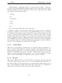
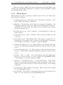
the data editor. The data editor is essentially an XML tree editor with a
1:1 mapping with the underlying XML.
Please see figure 2.1 for a picture of the XML editor.
First, let us take a quick look at the menus, there should not be many
surprises there. We have file and edit, edit only contains undo and redo.
Menu contains ”new”, ”open”, ”save”, ”save as”, ”export” which exports
data to Hank’s EDF format, and ”exit”. I take for granted that everyone
who reads this text has some experience with what these actions do from
working with previous programs and all I would like to add is that they
work just as one would expect them to.
At the bottom of the window a panel is dedicated to a context sensitive
help text that changes with the currently selected record. I am the first to
admit that the help text could be better, but it should hopefully provide
some idea of what values parameters should have. I have tried to copy
the relevant parts from the OpenDRIVE standard and have also added my
own comments where it made sense to do so, and while I have tried to get
everything right I make no guarantees that everything is 100% correct. In
case of any inaccuracies or uncertainties I refer the reader to the definitions
of EDF [1] or [2] OpenDRIVE.
The root node is OpenDRIVE, and it contains a number of child nodes
that in turn contain a number of child nodes, etc. I call these containers
categories. The basic idea is that you right click a category and add new
records. These contain properties and possibly more categories that can
be added to. As you go on adding new records to the categories and fill
them with data you create your scenario. If a record is no longer needed or
unwanted it can be deleted by right clicking it and selecting remove. Another
option that appears when right clicking a category is insert. Insert will copy
the currently selected record from the library to the selected container if it
is of the right type for the record. This is covered in more detail later on.
The tree can be scrolled up and down with the mouse wheel.
For more information about OpenDRIVE I refer the reader to the OpenDRIVE standard. [2]
The top level containers are:
• Hank settings
• Header
• Controllers
• Roads
• Junctions
• Global records
• Hank Intersection templates
10
2.3. HORN
CHAPTER 2. BODY
Hank settings contain the units to be used in the scenario. They are
not part of the OpenDRIVE standard which only works with meters. The
defaults should be good enough and work as one would expect, but EDF
also supports the following units:
• meters
• m
• kilometers
• km
• feet
• ft
For speed units mph is the only valid entry.
Header contains some metadata that may or may not be of interest.
RevMajor and Minor are the version of OpenDRIVE this scenario was made
in. Name is the scenario name, Version is some version number for the
scenario. Date would be the last time it was worked on, and it also contains
North, South, East, West which do not seem to have much actual use. The
vendor tells the user what company made the editor the scenario was created
in. In HORN the vendor attribute lists everyone who has worked on HORN.
It is currently only me, but I hope that more contributors can be added to
the list soon. Nothing here gets exported to EDF.
2.3.3
Controllers
The category Controllers contains a list of controllers. They are meant to be
used to control traffic lights for example, but they only define the what - Id,
Name, Sequence (priority over other controllers), and a number of Controls
that have a signal ID and a type. The how - instructions on how they are
meant to operate are however not present so I do not see much use for them
when working with HANK. Nothing here gets exported to EDF.
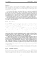
2.3.4
Roads
The main building block of a road network are also the category with the
most data and probably where you as a user of HORN will spend most of
the time working. Most important are geometries that define the layout of
the road and lanes that define what lanes exist along the road. I shall start
with the most useful categories and cover the others later.
11
2.3. HORN
CHAPTER 2. BODY
Geometries
Geometries are central to a road. They form the reference line that the
road follows and are the only thing that currently gets drawn in the map
view. Geometries are covered in detail in ”Geometrical figures in HORN”
and individual differences will not be covered here.
Common for all geometries is that they can be moved, rotated, and
scaled. Right clicking on a geometry will give a list of available options. If a
geometry is selected some additional options will also be made available by
right clicking on the map view (move here, rotate here). Move here moves
the record to the coordinates where the cursor was when the right click
occured. Rotate here changes the heading of the record so that it points
towards the coordinates where the cursor was when the right click occured.
It should also be noted that roads work just like geometry. Right clicking
gives the options to move, rotate, and scale it, and right clicking the map
view lets the road be moved or rotated to a point. Performing an action on
the road means performing it on all geometries that are part of the road and
it can therefore be thought of as a shortcut to repeating the same action for
all geometries manually.
Lanes
Another important part of a road are the lanes. Lanes flesh out the reference
curve of the geometry with driving fields. Under Lane sections there are left
lanes, center lanes, and right lanes. Left lanes are left of the middle of the
road, right lanes are right of the middle. It is also possible to have a special
center lane in the middle of the road. The center lane is supposed to have
some special conditions forced on itself which are currently not enforced,
but basically it may only be a single flat lane. While center lane is optional
there should only be one as there is only one center of the road there can
be any number of left and right lanes.
Lanes may have successors and predecessors just like roads, for merging for example. Center lanes are special in that they may not have any
successors or predecessors.
All lanes have a certain lane type, for example some lanes may be sidewalks, car lanes, or have special restrictions on who may drive there. The
type argument specifies this. Lanes also have a width, and at least one width
must be specified for every lane. EDF only handles a fixed width per lane
whereas OpenDRIVE uses a polynome to describe the width of a lane. For
exporting to EDF having a single width record with the parameter ”a” set
to the desired width should give the same result in both OpenDRIVE and
HANK. Lane width might vary along the road and are valid from the given
s-value until the end of the road or another lane width with a higher s-value
overrides it.
Lanes may also have road marks - lines, text, etc. painted on them. EDF
does not support this, but it is available for anyone who wants to use it.
12
2.3. HORN
CHAPTER 2. BODY
Roads may consist of different materials at different times. A material
in OpenDRIVE is defined as a starting point (s-distance from the start of
the road), a surface, a friction, and a roughness. EDF does not support this,
but it is available for anyone who wants to use it. Lane material may vary
along the road and are valid from the given s-value until the end of the road
or another material with a higher s-value overrides it.
Visibilities describes how far a driver can see in various distances at some
point and onwards until another visibility record for the lane overrides it.
The visibility can vary with the s-distance from the start of the road. EDF
does not support this, but it is available for anyone who wants to use it.
Speed records specify the speed limit from a point along the road until
overridden by another speed record. OpenDRIVE demands that the speed
limit should be given in m/s, but when exporting to EDF it is treated as the
speed unit specified in the Hank settings record (EDF only allows speeds
specified as mph). Speed limits may vary along the road and are valid from
a given s-distance from the given s-value until the end of the road or another
speed limit with a higher s-value.
Lanes also have Access records that are used to further restrict what
traffic may be in the lane. For example, pedestrians only, motor traffic only,
etc. The valid options are given in the help section. EDF does not support
this, but it is available for anyone who wants to use it.
Lastly, lanes may have height records that specify the height of the inner
and outer sides of a lane which for example allows us to create race tracks
that slope sideways slightly or specify that pavements are above the car road.
EDF has a single height parameter for a lane while OpenDRIVE has two.
I chose to use outer as the height value that gets exported. For identical
behavior between HANK and OpenDRIVE inner and outer should both be
set to the same value. Lane heights may vary along the road and are valid
from the given s-value until the end of the road or another lane height with
a higher s-value overrides it.
Objects
Objects are things that might be found in the world of the scenario, for
example cars, pedestrians, signs, road blocks, etc. They all have a type,
name, and unique id that OpenDRIVE wants us to fill in. Every object
has s and t coordinates that are essentially x and y coordinates relative to
the road’s reference line. s would be distance traveled along the line, and t
would be the distance relative to the middle of the road to where the object
is. zOffset is how high above the road the object is, valid length decides
how long the object may be, Orientation if it is facing towards or against
the direction of the road. Length and width can be used to describe object if
it is rectangular, and radius can be used if it is more oval. Only one should
be defined however. Height determines the height of the object, we also
have rotations in all axises: hdg (heading), pitch, and roll. Heading is the
direction the object is facing relative to the road’s direction (rotates around
13
2.3. HORN
CHAPTER 2. BODY
the z-axis). Pitch points the object up or down (rotates around the t-axis),
and roll makes the object lean to the sides (rotates around the s-axis).
It is possible to make an object repeat by adding a repeat to the repeats
category. This can be useful for saying for example that there should be a
streetlight every 10 meters.
It is possible to create an outline polygon to more precisely specify the
shape of the object. The polygon can either use coordinates relative to the
object or the road.
Just like lanes objects may also have a material which also has a surface,
friction, and roughness.
Just like lanes objects also have a validities category. The validity records
in it specify valid lanes for the object.
Finally there is the SDL parameter which was added on especially for
HANK scenarios and is not a valid OpenDRIVE construct.
The SDL lets the user enter SDL code that can create an object. It has
the ability to use all the object parameters directly by refering to them as
$property, for example $zOffset would be replaced with the zOffset of the
record. I added this so that objects could be used as templates and have the
same SDL code and only require the OpenDRIVE properties to be changed.
There are no restrictions on what values can be assigned to the OpenDRIVE
properties while exporting to SDL code, so they can essentially be treated as
variables if we so desire, but I recommend to try to keep the same meaning
allowing for easy porting in the future.
Features
Features are simply a string that is treated as a feature in EDF. Features
are special SDL code embedded in the EDF code. Features are not part of
the OpenDRIVE standard.
An example of the usage of a feature is listed at the end of the appendix
for those who are interested. Every feature is treated as a separate row in
the EDF code.
Range attributes
Range attributes are simply a string that is treated as a range attribute in
EDF. Range attributes are special SDL code embedded in the EDF code.
Range attributes are not part of the OpenDRIVE standard. The only example of range attribute I have seen in EDF was to specify a speed limit,
i.e. range attributes { speedlimit (35.0, mph); } Every range attribute is
treated as a separate row in the EDF code. Again, I have only seen speed
limits of mph used, but it is possible that other units might work.
14
2.3. HORN
CHAPTER 2. BODY
Predecessor/Successor/Left neighbor/Right neighbor
A road typically has a predecessor and a successor and can also have a left
and right neighbor. These are OpenDRIVE features that easily allow you
to define connectivity between roads by entering their IDs. EDF does not
have this feature but HANK figures out the connectivity automatically.
Types
Types are an optional way of paritioning stretches of a road into various
types, for example a road could go from a motorway into a town road and
end up as a pedestrian road. Specifying type of road is optional in OpenDRIVE and is ignored when exporting to EDF but might help with organizing things. Road types may vary along the road and are valid from the
given s-value until the end of the road or another type with a higher s-value
overrides it.
Elevations
An elevation uses a cubic polynome to specify how the height of the road
varies over distance from the start point s. EDF also allows specifying a z
value as part of the road’s reference line and therefore the ”a” variable of
elevation can partially be exported to EDF. Elevation might vary along the
road and is valid from the given s-value until the end of the road or another
elevation with a higher s-value overrides it.
Super elevations
Super elevation uses a cubic polynome to specify how the road is rolled by
rotating it around the S-axis. The value used in the equation is the distance
from the starting point ”s”. I am not sure why or when this would be
useful outside of designing a rollercoaster, but it is part of the OpenDRIVE
standard and there if you want it. It is not a part of EDF and is ignored
when exporting to EDF. ”a” is given as radians. Super elevation may vary
along the road and are valid from the given s-value until the end of the road
or another super elevation with a higher s-value overrides it.
Crossfalls
While Super elevation rotates the road around the s-axis crossfall rotates
the road around the t-axis. The value used in the equation is the distance
from the starting point ”s”. I am not sure why or when this would be useful,
but it is part of the OpenDRIVE standard. It is not a part of EDF and is
ignored when exporting to EDF. ”a” is given as radians. Crossfall may vary
along the road and is valid from the given s-value until the end of the road
or another crossfall with a higher s-value overrides it.
15
2.3. HORN
CHAPTER 2. BODY
Lane offsets
Lane offsets use a cubic polynome to describe a lateral shift of a lane relative
to the reference line and can be useful for modeling some special roads, for
example the 2-1 road. They have no counterpart in EDF and are ignored
when exporting to EDF. Lane offsets may vary along the road and are valid
from the given s-value until the end of the road or another lane offset with
a higher s-value overrides it.
Signals
Signal records contain information about some sort of traffic signal, including
where it is at relative to the road (s and t coordinates, zOffset). Signals may
have a name and a unique ID, they may be dynamic (yes/no), they may face
either direction of the road (orientation), and a number of parameters used
to describe what kind of signal it is (country, type, subtype). Signals may
also have some arbitrary value that I suppose is specific to various simulators
as well as a list of lanes they affect (validities). Signals are not exported to
EDF at the moment, but perhaps there could be some support added later
by someone who better understands what kind of objects are valid in both
standards and is able to map between them.
Object and Signal references
References are used to avoid multiple definitions of the same thing. The idea
is that one road ”owns” an object or a signal, and then other roads that
are affected by them use a reference to them. The reference must specify
where they are relative to the road, the id being refered to, the lanes being
affected, and the direction of the road being affected. In addition to the
previous attributes object references also have a valid length attribute that
specifies the stretch of road (s-length) affected by the object.
References are currently ignored when exporting as EDF treats objects
as global things and lacks the concept of references.
Tunnels / Bridges
Tunnels and bridges are, well, tunnels and bridges. They define a stretch of
road as a tunnel or a bridge through a start s-value and a s-length. They
have an id and a name and a type. For bridges type is the material the
bridge is made from, in tunnels it is a classification of underground tunnel
or underpass. In addition tunnels have lighting and daylight parameters
that both go from 0 to 1 allowing us fine control over the lighting inside the
tunnel. EDF has no concept of a bridge or tunnel and these are therefore
sadly ignored when exporting to EDF, but they are there should you want
to use them anyway.
16
2.3. HORN
CHAPTER 2. BODY
Surfaces
Surfaces consist of curved regular grids (CRG). [3] CRG seem to be essentially a height map of the surface of a road (A big 2 dimensional array where
every element is an equal distance from their neighbors with height values
measured for every point).
So for those who want to use them CRG can be used in OpenDRIVE
to add some very fine details to the road and require a file name, start and
end points on the s-axis, a surprising orientation parameter (surprising as
the orientation can be derived from the sStart and sEnd parameters which
OpenDRIVE uses for other records), a mode (attached or genuine), and s,
t, z, and heading offsets as well as a scale parameter for the height data.
EDF unfortunately does not support this and it is ignored when exporting, but they are still available as part of the OpenDRIVE standard should
you want to use them anyway.
2.3.5
Junctions
In OpenDRIVE a junction is simply a place where a road ends and turns
into one or more other roads. They contain lists of connections to other
roads, priorities for deciding right of road, and controllers used to manage
the junction as well as a name and Id.
I have extended it to be used with EDF’s intersections by adding the
parameters template and x, y, and z. When exporting, the intersection will
be created as an instance of the intersection template and be translated to
x,y,z.
Related to junctions are of course also roads. Roads may belong to a
junction and if they do then OpenDRIVE refers to them as paths and they
are then analogous to the corridors of EDF. We make a road a path by
setting the road’s junction parameter as a non-default value.
Connections are bound to road slots in the template through the Incoming road slot and Outgoing road slot attributes in the Connection record.
I found it very surprising that EDF has a far more fine grained control for
how intersections are implemented compared to what OpenDRIVE has to
offer. While my solution is a bit ugly it should work somewhat smoothly
with a minimum of extending OpenDRIVE. Just remember that files making heavy use of this extension will not work if there is a move from Hank
to OpenDRIVE.
To recap: Bind a junction to a template by adding the template name,
bind roads to template slots, place it in the world using the x, y, z variables.
2.3.6
Global objects
Global objects are not part of OpenDRIVE but are a part of EDF. Global
here refers to the fact that they are not owned by any particular road, and
could for example be a tree, a house, or a boat in the distance. EDF and SDL
17
2.3. HORN
CHAPTER 2. BODY
do not make any difference on where an object is created or if it is associated
with a road or not, so global objects is added more as a convenience and
help in organizing scenarios logically than a strict requirement, and should
you prefer to do so all objects can be listed on the object list of a single
road with coordinates relative to the road and it should still work out in the
end. One difference between global and road objects is that $road which is
replaced with the name of the exported road is not valid for a global object
as they do not belong to a road. Just like local objects HORN provides a
convenient move dialogue for global objects.
2.3.7
Hank intersection templates
As the name implies Hank intersection templates are intersection templates
from EDF and are not part of OpenDRIVE. In EDF templates are used
heavily for both roads and intersections, but intersections require a template
to work well.
For the purpose of exporting to EDF junctions that were discussed above
are instantiations of these templates and refer to them for their geometry
through the name parameter. I have been unable to find any documentation
about this and have reverse-engineered the format myself. There may be
inaccuracies from this in my implementation, but I am unaware of any.
Intersection geometries
Templates define an intersection area as a polygon who’s edges are formed
from a number of points. Each point defines a road slot that can be associated with a corridor in the corridors category. When put together the
points form lines and the lines are what the road slots are attached to, for
example if p1 defines the slot r1 then the line p1p2 is the edge that we will
attach r1 to.
Although only one point is entered it is implicit that the line that is
formed between this point and the following in the polygon (the last point
will draw a line to the first point) is what is used to define the corridor.
Junctors are essentially lanes inside an intersection and the name used
here must also be used when creating corridors later. The left and right
junctors categories just mean that they appear left or right of the [] expression inside the parameter list. For example ”-9.0 14.0 0.0 (P1 P2 [0.5, R1]
P3 P4)” is what a geom row might look like in EDF. P1, P2 would then be
in left junctors, and P3, P4 in right junctors. While they obviously are used
to map between lanes and corridors somehow I have not found any rules for
how it works. Good luck!
Intersection corridors
As was mentioned previously a corridor is an internal road inside an intersection that goes from a start junctor to an end junctor. The junctors are
18
2.3. HORN
CHAPTER 2. BODY
connected to incoming and outgoing roads in the intersection.
The corridor has a name that is unique in the intersection.
We decide what traffic is allowed on the corridor using the same types
as roads in EDF.
Corridors have a stop line end and an end from which traffic flows. These
are called stopline junctor and flow percentage junctor and should have the
same name as the corresponding start and end junctors. The stop line has
an associated distance from the junctor, and the flow percentage junctor has
an associated flow percentage.
A special type of intersection is a pedestrian crossing. For these we may
have a curb junctor and an associated curb distance (How high the pavement is above the road). There is also the somewhat mysterious parameter
num segments which controls how many control points are used when creating the corridor. For a normal intersection a value between 5 - 20 should
work well.
Associated with a corridor are dependencies and points. It seems that
dependencies are used for creating a chain of conditions that must apply
before people may pass, for example there could be dependencies such that
a traffic light must be green and all other traffic lights must be red before
cars are allowed to drive through.
Points are available, but I was never able to figure out for what. In the
examples I have had available points and dependencies were never used, but
they are there for you should you need them.
I should mention that although corridors are very similar in concept to
OpenDRIVE paths corridors seem to be created to automatically form a
line between its two junctors so there is no good way to convert paths to
corridors.
Intersection traffic control objects
A traffic control object is essentially a wrapper around the line instance name
object type (parameter1, ..., parameterN), and as such you simply fill it in
with the desired name of the object in instance name, the type of the object
in object type, and the parameters it should have as a comma separated
string in parameters.
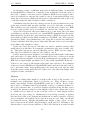
2.3.8
Library
The library is meant to be used to store commonly used objects and templates. While it could use some polish it does just that. Please see figure
2.3 for a picture of the library.
The library has its own set of menus that mirror the editor’s menus apart
from export which is not a valid operation on a library.
The main part of the library has an XML editor that works exactly
like the one in the data editor with the only difference being that it has a
different root node with different available operations.
19
2.3. HORN
CHAPTER 2. BODY
While the editor has an OpenDRIVE root the library does not actually
have a root, instead it works with categories that can be created by right
clicking on the background or on a category and selecting Add Category.
Categories are just containers that can contain other categories as well as
objects. While they start with no name categories can be given any name
by double clicking on them and typing in a name. For example we could
set up a category system for roads that store roads in sub-categories like
”straight”, ”curvy”, ”roundabout”, etc.
Right clicking on many objects gives the option insert ”object name”.
This option copies the currently selected record in the library to the currently
selected record container in the editor. Likewise we can copy the currently
selected record in the editor to the library by right clicking on a category in
the library and selecting ”Copy object here”.
The libraries currently have the file ending .hlib (”Horn Library”).
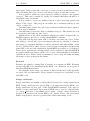
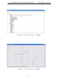
2.3.9
Road map view
Finally we have the Road map. Please see figure ?? for a picture of the
map. The road map displays the roads as lines seen from above. The lines
are drawn according to the layout of the road and are color coded according
to their geometry type. There is not much more to say about what is on
the map, so here follows what we can do with it:
The map can be scrolled with the arrow keys or the wasd keys. Holding
shift scrolls 10 times faster than normal. The current position of the bottom
left corner is indicated by X: and Y: in the bottom left of the window.
ctrl + and > and ctrl scrolling forward on the mouse zooms in. ctrl and < and ctrl scrolling back on the mouse zooms out.
Zooming is done in powers of 2, so every zoom level is twice or half as
large as the previous. The map is ”centered” on the bottom left corner which
means that zooming in will produce a larger version of the bottom left part
of the map, I went with this approach instead of the more intuitive ”middle is
the center” approach because I felt that it was more convenient to mentally
add units to the bottom left corner rather than adding or subtracting around
the middle and this way we also avoid having to somehow indicate where
the middle of the map is.
It is also possible to zoom by pressing enter and entering a zoom percentage (500 would magnify the image 500% for example). Ctrl 0 restores
the default zoom level. At the bottom of the screen ”scale:” indicates how
many units (OpenDRIVE wants us to use meters, but as HORN has to work
with HANK which allows multiple units that is not possible to enforce), and
likewise x units per line simply means that there are so many units between
the lines that form a regular grid to provide a convenient ruler. Additionally
there are some light grey lines which simply are drawn for every 4th line.
I found 4 to be a nice number for quickly measuring with the eyes while
providing some granularity.
20
2.4. GEOMETRICAL FIGURES IN HORN
CHAPTER 2. BODY
Right clicking on the map can bring up a context sensitive menu with
contents that vary depending on what was selected. Currently only roads,
road geometries, and objects support right clicks and can be copied, moved,
rotated, and scaled. Geometries and roads can also be moved to or rotated
in the direction of the cursor.
2.4
Geometrical figures in HORN
2.4.1
Geometries
First of all we need to have a quick refresher on radians because OpenDRIVE
works in radians, and as HORN tries to follow OpenDRIVE as literally
as possible angles are entered as radians in HORN. As everyone surely is
familiar with 180◦ = π, so radians = (desiredangleindegrees) ∗ π/180 (and
degrees = (desiredangleinradians) ∗ 180/π.)
Geometry in HORN is used to describe the layout of the road. Common
to all geometries are the attributes:
• Start point (x, y) - The absolute x,y coordinates in world space where
the geometry starts.
• Length - How many units long the geometry is. When talking about
length it is refered to as S in formulas.
• Heading - The rotation of the geometry measured in radians.
• End point (x,y) - The absolute x,y coordinates in world space where
the geometry ends. Using this as a start point for following geometry
is a good idea.
• End heading - The tangent of the direction the geometry is pointing
in at its end point. Using this as the heading for following geometry
is a good idea.
I have chosen to expand a little on these for some geometries where there
is more to say.
In OpenDRIVE geometries are implemented as a geometry record followed by a record that describes what kind of geometry it is. There are 6
different geometrical figures in HORN.
These are:
• Line
• Arc
• Spiral
• Polynome
21
2.4. GEOMETRICAL FIGURES IN HORN
CHAPTER 2. BODY
• Hank Spiral
• Spline
This section will try to explain how to work with them and give a background to how they are implemented. Before explaining more about them I
feel it is important to explain what Curvature is, as it is central to many of
these geometries.
2.4.2
Curvature
It is well known that the area of a circle is π ∗ radius2 , and circumference
is 2 ∗ π ∗ radius. Curvature is defined as the slope of a circle for some point
along the circumference which turns out to be 1/radius for all points on
the edge of the circle, that means that the bigger the circle is the lower the
curvature is (If you draw a small circle you need to turn your hand faster
than if you draw a larger circle where the curvature is lower). You can think
of the curvature of a point as the amount the curve bends in that point. In
a circle (and a line where it is always 0) curvature is constant, but in other
geometrical figures like spirals, splines, and polynomes it can vary.
It also turns out that the curvature and length can be used to measure
an angle. Recall that the circumference of a circle is 2 ∗ π ∗ radius. 2 ∗ π is
360 degrees measured in radians, or a full rotation of the circle. Curvature
is 1/radius, so radius is 1/curvature. The angle the arc measures is then
length/radius. It is useful to allow negative curvature even though it would
be bizarre to have a negative radius. The angle is then calculated as above,
and after obtaining it the radius is negated so it is positive again, the angle
will then be a negative angle and will imply a rotation in the other direction.
When working with curvature it is important to remember that curvature
= 1 / radius, so a curvature of 0 means no radius (”a straight line”), and a
curvature of 0.001 means a radius of 1000 units whereas a curvature of 10
means a radius of 0.1 units.
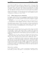
2.4.3
Line
Lines are used to represent straight road segments as part of the geometry
of the road.
I am sure we are all familiar with lines, they are drawn between a start
point and an end point. The start point is given as (x, y), the end point
is given in polar coordinates (a heading measured in radians and a length).
To be precise the end point is at x + cos(hdg) ∗ length, y + sin(hdg) ∗ length.
Another way to think about it is to imagine a line that gets drawn from (x,
y) to (x + length, y) and then gets rotated by the heading.
When designing a road network, lines will probably be frequently used
as most roads are straight for long stretches, so it is important to be comfortable with them. It is common for long lines to connect to spirals which
22
2.4. GEOMETRICAL FIGURES IN HORN
CHAPTER 2. BODY
then connects to an arc to form a curve, which then connects to another
spiral and ends with another long line. Using this composition it is possible
to recreate every shape of a road.
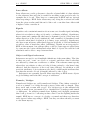
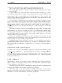
2.4.4
Arc
Arcs are used to represent turns in a road with a constant curvature as part
of the geometry of the road. An arc represents a segment of a circle, or a
semi circle if you will. They are generally only used to create a curve in the
road and are connected to spirals at each end to create a smooth transition
between lines and the curve.
An arc consists of a start point, a curvature, a length, and a heading.
I found this representation fascinating as it is possible to derive all the
information about a circle from this, as described above about curvature.
They are drawn as follows:
If the curvature is positive OpenDRIVE wants the drawing to start from
−π/2, and if it is negative it should start from π/2.
In practise this means that a positive curvature forms a left turn, and
negative curvature a right turn as seen from the road the driver came from.
While it might be a bit counter intuitive this is just how OpenDRIVE is
designed.
The middle point is then calculated by rotating the vector (0, radius)
(or (0, -radius) if it is a negative angle) by the heading, and adding the
resulting vector to the start point. Essentially we are stating that if we are
at the bottom of the circle the middle is radius units above (or below if it
is a negative angle) the starting point as it is at the lowest/highest point of
the circle.
The rotation is necessary as after rotating the start point by the heading
the middle is no longer at (0, +/-radius), but at some other point along
the circle arc. This effect can easily be seen by drawing a circle and a line
through the top to the bottom of it, and then rotating the paper. It is the
absolute coordinates of this line that needs to be calculated when rotating
the start point.
After knowing the middle point the end point is easily obtained by multiplying the radius with the cos/sine values of the angle and then rotating
the resulting vector by the heading. Or, more concisely:
StartP oint(xStart, yStart) = (x, y)
M iddlepoint(xM iddle, yM iddle) = (xStart, yStart)+rotate(heading, 0, radius)
Endpoint(xEnd, yEnd) = (xM iddle, yM iddle)+rotate(heading, cos(angle)∗
radius, sin(angle) ∗ radius)
where rotate rotates with heading the x and y values given to it. Wikipedia
[12] and mathopenref [13]covers most of this.
23
2.4. GEOMETRICAL FIGURES IN HORN
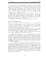
2.4.5
CHAPTER 2. BODY
Spiral
Spirals are used to represent a spiral segment that connects a line segment
with a curve segment or possibly another spiral segment as part of the
geometry of the road.
It has the following properties:
• Starting point (x,y) - The start point of the spiral in absolute coordinates.
• Length - The S-length of the spiral. If the spiral is very long compared
to the curvature it interpolates it and draws ever smaller circles.
• Heading - The heading of the spiral as measured in Radians. By
default the spiral is rotated by 0 degrees but changing this rotates
everything by the entered amount.
• Start curvature - The curvature the spiral has at Starting point.
• End curvature - The curvature the spiral has at the end point.
In HORN as well as in both EDF and OpenDRIVE a spiral refers to an
Euler spiral, also known as a Clothoid. There are many kinds of spirals with
various properties, but what separates a clothoid from other spirals is that
it has a linearly changing curvature. Put another way, the curvature can be
described with the equation K = dK ∗ S + m (same as the equation for a
line, but typically m is 0, and in the standard clothoid dK is 1.) Let us call
the curvature K, then the derivata dK/dS is a constant value.
While a circle has a constant curvature the curvature of a spiral increases
linearly with the distance S traveled along it, so that curvature(S) = dK ∗S
where dK is calculated as the difference in curvature between the start
and end curvature of the spiral divided by the length of the spiral, or
dK = (endCurvature − startCurvature)/length. Remember that increasing curvature means decreasing radius, so the distinct look of a spiral is a
continuous line that spins around forming ever smaller circles much like the
shape of water draining from a bathtup. From this we can see that if the
difference between start and end is large relative to the length of the spiral
then it will make a smaller circle than if the difference in curvature is small
relative to the length of the spiral.
A spiral smoothly interpolates between two curvatures, where one of
them is typically 0 and are often seen used in roads and railways as the
optimal transition between an arc and a line as the centripetal force is
minized. Spirals can also be found in many places in nature, for example in
sea shells and bird feathers 1 .
1 (as I accidentally discovered when I got my rendering code wrong and it ended up
drawing pictures of them)
24
2.4. GEOMETRICAL FIGURES IN HORN
CHAPTER 2. BODY
The tangent of a point in a spiral is easily obtained with the simple
formula tangent = (dK ∗ S 2 )/2 which is the primitive function of the line
formula.
There should be some way of easily obtaining the x/y coordinates of a
point in a line using integrals but I was never able to work it out for cases
where the curvature does not start at 0.
Luckily it is also possible to obtain good approximations of the x/y values
by starting with S = startCurvature and then successively calculating the
tangent of the spiral for S and multiplying it by some small stepsize to obtain
a line that can be drawn from the end of the previous line. The stepsize
is also added to the S-value and we can repeat this process until the entire
spiral length has been stepped through.
This inherently leads to two problems: a) A small error is introduced
from taking discrete steps (From my experience it gets wrong around the
10th to 12th decimal), and b) as drawing a spiral consists of taking many
small steps having a huge spiral is impractical, so entering some unrealistically large spiral could slow down the drawing speed to a crawl. In practise
it works great though, and using the suggested spiral endpoints in the program makes them line up nicely with the ones from sample OpenDRIVE
scenarios.
I found spirals to be poorly explained in the few texts I have found about
them, and most of what I know has come from essentially researching spirals
by myself. The above might not be a complete mathematical background
and might sound confusing, but should be sufficient to get you started experimenting with spirals in HORN. They are amazing things of beauty that are
found throughout nature, and our roads could not be built without them.
The correct way to use them is to attach one end with curvature = 0 to
a line and another non-0 end to an arc, then attach another spiral from the
arc to a line. EDF requires one end to be 0, but if exporting to EDF is not
important it is possible in OpenDRIVE to make an S-shaped curve by using
negative to positive curvature, or to make a spiral that interpolates from
one arc to another. Wikipedia [11] has a writeup that was fairly useless to
me, but which might be interesting for those who want to know more about
the math relating to spirals.
2.4.6
Polynome
OpenDRIVE refers to cubic polynomes as polynomes. They are used to
represent a cubic polynome segment as part of the road. They have the
following attributes:
• The polynome itself - A cubic polynome is given by the formula y =
a + b * x + c * x2̂ + d * x3̂. a,b,c,d are parameters we can edit in
HORN and OpenDRIVE.
• Length - Values in the range 0 .. Length is used to calculate y values.
25
2.4. GEOMETRICAL FIGURES IN HORN
CHAPTER 2. BODY
• Starting point (x,y) - The start point of the polynome in absolute
coordinates. This point is treated as 0,0 for graphing purposes.
• Heading - The heading of the polynome as measured in Radians. By
default the polynome is rotated by 0 degrees but changing this rotates
it by the entered amount.
A polynome is a part of the OpenDRIVE standard but not EDF. As
such they are valid in OpenDRIVE but useless for working with HANK.
They are used to make the graph for f (x) = a + b ∗ x + c ∗ x2 + d ∗ x3 a
road segment. It does not follow the usual standard that Length is the arc
length of the segment, instead it just tells us how long the range of x values
used in the graph should be.
2.4.7
Spline
Splines are used to represent a spline segment as part of the road. They
have the following attributes:
• Starting point (x,y) - The start point of the spline in absolute coordinates.
• Heading - The heading of the spline as measured in Radians. By
default the spline is rotated by 0◦ but changing this rotates it by the
entered amount.
• Start tangent - The tangent for the first point.
• End tangent - The tangent for the end point.
• Points - A list of points. With 2 points a line is drawn between them,
with 3 or more points pretty curves are drawn.
• orientation - ”positive” or ”negative” orientation for the spline.
• num segments - How many segments should be used by HANK to
create it.
A spline is a mathematical function that interpolates between two values
in a smooth way. The term comes from the spline tools engineers used when
planning roads and railways in the past, they essentially put nails in a board
as points a line should go through and dragged a thin metal sheet along the
path marked by the nails so it was forced to bend smoothly and make nice
curves. These could then be copied and magnified and put to use in the real
version.
A spline in HORN consists of a series of cubic bezier spline segments.
A cubic bezier spline segment has a start point, two control points, and an
end point. [10]
26
2.4. GEOMETRICAL FIGURES IN HORN
CHAPTER 2. BODY
EDF uses splines (They are not part of the OpenDRIVE standard) but
only specifies the start and end points as well as several control points in
between that the line must pass through. A cubic bezier spline segment
requires five control points: A starting point, an ending point, and 3 other
control points that affect how the line is curved. While there are no control
points before the first or after the last points there are instead tangents that
fill the same purpose. As the 3 control points are not defined in the data by
the user they are calculated as follows:
There are three points we need to consider: The previous point - a, the
current point - b, and the next point - c. Each of a, b, and c has a tangent
associated with it: a.t, b.t, c.t.
To calculate t for all control points but the start and end points of the
spline we need a starting point and an ending point. The starting point t1
is achieved by calculating the mid point for the line ab, and the end point
t2 is the mid point of the line bc.
Or, to use formulas:
t1 = (b.x − a.x, b.y − a.y)/2
t2 = (c.x − b.x, c.y − b.y)/2
t = t2 − t1
the points needed are then:
a
b
b + (b.t/2)
c − (c.t/2)
c
Repeating this process starting with b as the second point of the spline
and shifting the points so b becomes a, c becomes b, and a new point
becomes c in a new cubic bezier spline until all points have been used we
are able to draw a spline that goes through all the spline points accurately.
To read more about how it works I refer you to [9].
While splines are not really required to make a road (you can achieve
anything with the right combination of lines, arcs, and spirals) splines are a
nice addition to the arsenal for when you quickly would like to model some
set of continuous curves. They are however not a standard part of OpenDRIVE (but EDF uses them), and so I would recommend that they should
be used as little as possible to achieve compatibility with other simulators.
They are however available and working well if you are happy with making
an EDF only scenario.
I chose to make splines an extension of geometry, so in addition to all
their normal EDF parameters they also have a heading, and a start and end
position that work as one would expect. Just like geometry they can be
scaled, moved, and rotated.
27
2.4. GEOMETRICAL FIGURES IN HORN
CHAPTER 2. BODY
When exporting to EDF the extra parameters modify the spline data
creating the desired EDF definition, so when it is run in HANK it should
look just like in the editor.
2.4.8
Hank Spiral
Hank spirals are used to represent a spiral as part of the road. They have
the following attributes:
• Starting point (x,y) - The start point of the spiral in absolute coordinates. This gets added to whichever
• Heading - The heading of the spiral as measured in Radians. By
default the spiral is rotated by 0 degrees but changing this rotates everything by the entered amount. This rotation is added to the rotation
from the tangent vector.
• straight end (x,y,z) - The coordinates of the straight end. Only one
end is needed.
• curved end (x,y,z) - The coordinates of the curved end. Only one end
is needed.
• mid point (x,y,z) - The middle point of the spiral, it appears to be
superfluous as everything can be derived from the other parameters
but it might be necessary to specify to appease HANK.
• straight end tangent (x, y, z) - The tangent of the straight end given
as a vector. When using straightToCurved the spiral is rotated by this
vector.
• curved end tangent (x, y, z) - The tangent of the curved end given as
a vector. When using curvedToStraight the spiral is rotated by this
vector.
• bearing - ”left” or ”right” - left is the default value and right simply
mirrors it. I am not aware of a way to mirror an OpenDRIVE spiral
so this might be a positive feature for EDF.
• direction - ”straightToCurved” or ”curvedToStraight”. This affects
which of curved end and straight end is used as the start point of the
spiral as well as the direction of the spiral (increasing or decreasing
curvature).
• spiral length - The s-length of the spiral. This is the same as length
for an OpenDRIVE spiral.
• spiral radius - The radius of the spiral at the curved end which is the
same as 1/end curvature for an OpenDRIVE spiral.
28
2.4. GEOMETRICAL FIGURES IN HORN
CHAPTER 2. BODY
• num segments - How many segments should be used by HANK to
create it.
• super elevation - While EDF does not seem to support super elevation
in general it does allow super elevation in spirals. This is a single value
which makes the entire road lean to the left or right.
Hank Spirals are used just like Spirals and equivalent spirals will look the
same. In HORN, HANK spirals are internally converted to spirals before
they are drawn. They are not part of the OpenDRIVE standard and are
provided because they are part of the EDF standard. As such they are
not recommended to use for scenarios that should be portable, but they
are available if you want to use them. The main difference is that it uses
a different, more complicated format to achieve an inferior spiral (One end
HAS to be straight whereas for a OpenDRIVE spiral it can be straight and
it comes with many useless parameters). Regardless of which spiral you
choose to use you still have to conform to one end being straight or there
will be problems in HANK later.
I chose to make HANK spirals an additional specialization of geometry,
so in addition to all their normal EDF parameters they also have a heading
and a start position that work as one would expect. Just like geometry they
can be scaled, moved, and rotated and when exporting the extra parameters
modify the result so when it is run in HANK it should look just like in the
editor.
29
2.4. GEOMETRICAL FIGURES IN HORN
CHAPTER 2. BODY
Figure 2.1: The XML editor of HANK.
30
2.4. GEOMETRICAL FIGURES IN HORN
CHAPTER 2. BODY
Figure 2.2: The library editor of HANK.
Figure 2.3: The map editor of HANK.
31
Chapter 3
Closing
3.1
The development process
We originally agreed that the editor should work directly with EDF and SDL
and it seemed like a nice little project. It was unknown at the time how
complicated getting spirals and splines, and arcs to work well would be, had
we stuck with HANK only it would probably have been possible to leverage
some of the source code for HANK to make the editor WYSIWYG in a pinch.
The additional requirement of working with the OpenDRIVE standard was
added later which seemed reasonable at the time and it still makes sense
as a requirement as OpenDrive is a very nice standard with good support.
Unfortunately the addition of OpenDRIVE turned out to hugely complicate
everything by forcing me to implement many, mostly useless (from the perspective of someone who wants to create HANK scenarios) classes, for the
sake of simply having them available so the OpenDRIVE standard would
be implemented. As OpenDRIVE is based on XML it is very hierarchical
and a tree editor was needed to handle the imposed tree structure of the
OpenDRIVE data as opposed to a more user friendly approach I originally
had in mind. I wanted to use HANK objects and geometry selectable on
a map with a properties view for the selected object and a panel where
new objects could be selected and be dropped on the map where they were
wanted. OpenDRIVE simply does not make much sense in that context as
most of the data in OpenDRIVE is not an actual object a user would be
able to manipulate graphically from a 2d perspective.
The first milestone of the project was reading through the OpenDRIVE
specification and writing code that could load an OpenDRIVE file. As
OpenDRIVE is based on XML it made sense to use tinyXML which is a
great C++ library for both loading and saving XML files. It was easy to
get into and easily let me save and load XML data. I warmly recommend
it for anyone who has a need to write a program that works with XML.
To implement the GUI I chose to use Qt which I had heard many good
32
3.1. THE DEVELOPMENT PROCESS
CHAPTER 3. CLOSING
things about and as a GUI toolkit it is both intuitive and powerful with a
lot of useful gems sprinkled all over the place. However it suffers from what
I feel are some fundamentally bad design decisions that makes it difficult
to work with that I will shortly discuss here and I advice to try a different
framework or GUI toolkit if you have not used Qt before or do not have a
good reason to use it.
In Qt almost everything derives from the base class QObject which is all
good, but some classes are not derived from QObject and are antagonistic
with it to the point where a subclass may not inherit from both and the nonQObject classes are then not valid to pass around to other Qt methods as
parameters. This would not generally matter, but Qt only allows callbacks
on QObjects (more on this later), and callbacks were required to get things
to work with Qt.
A workaround I discovered by myself after much fuss was to have a subclass that contains an object that derives from QObject that also contains
all the data and the non-QObject class’ methods then refers to the data in
the QObject subclass object in its overriding methods.
For example:
class foo : QObject {
int data;
...
};
class bar : QTreeNode {
foo *myData;
...
void doSomethingUseful() {
doSomethingInQt(a);
}
};
is the only construct I came up with that let me work with some parts of
Qt. The tree nodes in particular were very difficult to work with and took
a long time to implement well.
Initially the idea was for all classes to subclass QObject and contain a
text field that they provide custom behavior for. It was going to be clean,
simple, and very little room for problems. It might have been possible to
somehow implement that design, maybe something could have been hacked
together by using qTreenode subclasses, but during the project it never
worked out. Using Qt was probably a bad idea in hindsight as it’s support
for tree editing was questionable and not really the focus of the framework.
Eventually HORN became the current convoluted mess with HankTreeNode instead. A HankTreeNode is basically a text field in the tree editor with
33
3.1. THE DEVELOPMENT PROCESS
CHAPTER 3. CLOSING
a void* to some variable, an editableObject* to the owner of the variable and
an enum describing the type of the variable. Custom behavior is obviously
not possible this way, and a large part of HORN’s code became constructors
creating the HankTreeNodes.
Another problem with Qt was that it is a GUI toolkit without callbacks.
Instead of callbacks some obnoxious macros need to be run through a preprocessor, it was never clear when the preprocessor needed to be run, but
it was usually a good idea to clean the build and run the preprocessor and
then perform a full build to see if mysterious problems that often occured
would go away.
Instead of callbacks the macros use slots and signals. The idea is that
objects emit signals and other objects can be bound to listen to signals from a
certain object and have a certain method called when the signal is received.
The methods are called slots and must have the same parameters as the
signal method. This construction is very error prone as Qt will happily let
you call a method that does not exist as the macro overrides any compiler
error checking and then nothing happens when the program tries to call it.
Slots and signals also appeared both restrictive and confusing as seemingly obvious things like binding a slot from another object in the code inside
the current object to the signal from a third object which was a surprisingly
common situation for me and something I was forced to design my way out
of by moving things around. I also felt that it led to very verbose code
littered all over my constructors that did nothing but cause problems and
waste space when all I wanted was to be able to pass a function pointer to
an object. It is possible that there are things slots and signals are good for,
but I was unable to find any situation where a simple callback had not been
better and far less messy and error prone.
These two issues are responsible for the huge constructors for most of
the HORN classes which also ended up being large time sinks.
Eventually it was possible to get around much of the problems and
HORN was able to get a window with a tree editor that loaded OpenDRIVE
files and displayed the data in a proper hierarchy.
The next obvious steps were making the data editable and saveable.
Originally HORN was going to use an XML saving class written by me
with syntax similar to cout, which also had methods to convert from basic
datatypes to strings, something that is shockingly missing in C++’ standard
library.
While there was nothing wrong with the code HORN was for some unknown reason unable to write to a file. The program code that gets directly
compiled into the executable is physically unable to write to files, any kind
of files, both C functions and C++ methods just fail.
A lot of time was spent figuring out what was wrong with perfectly fine
code before it became necessary to give up on it. A second attempt was done
using tinyXML and surprisingly it worked just fine. While it still makes no
sense it became clear then that something very wrong was stopping file
34
3.1. THE DEVELOPMENT PROCESS
CHAPTER 3. CLOSING
output that was compiled as part of HORN from working, but if the exact
same code was compiled separately as a library and linked in it worked
just fine. Later on when HORN was supposed to write EDF files the same
problem came back, but tinyXML was not useful for creating text files.
Much later on when the priority of the project became exporting files
to EDF I reasoned that tinyXML did not fail to write although everything
else I tried did, and tinyXML is a separately compiled library, so a library
that is just a wrapper around file operations was created in the hopes that it
would work around the problem I was experiencing, and it worked very well.
The wrapper worked much like what was originally the plan and therefore
replacing the exporting code only required some tedious manual replacing
of function calls in the right places and no rewrites.
To this date the program is unable to use fwrite and fstream to save data
if the code is not from a library. This may be related to Qt or the version of
GCC Qt Creator ships with, but it is definitely something to look out for.
After a lot of struggling with the above problems HORN could load, edit,
and save OpenDRIVE data with many obscure bugs and a very large body
of classes that needed to be implemented along with a forcibly complicated
design.
By this time the 3 months of planned time for the project had run out
but it seemed like HORN was nearly complete. How hard could it be to
make the program draw some data and export the data from OpenDRIVE
to EDF and adding undo/redo functionality and some other minor things?
A new goal became to try to be done before 5 months and work on HORN
kept on going. After all it seemed like the hardest part was already done
and HORN would be done soon.
Adding undo and redo was surprisingly simple by contrast to everything
that had previously been done before and mostly went smoothly and in the
end the resulting design was as good as it could be.
QT uses an undo stack where you can push objects that inherit from
QUndo. These must override the undo() and redo() methods and that is all
there is to it. The tree used in the editor is a subclass of a QTreeWidget
that overrides the currentItemHasChanged method (Qt calls it when a not
currently selected node in the tree is selected). The function does a number
of checks to see what updates need to be done to the underlying objects
based on what kind of object the modified text belongs to. If it thinks that
the action needs an undo action the previous text is stored in a new undo,
and the node is updated to use the new text. When undoing the old value
is simply converted back to the variable the datanode refers to and the new
value is stored instead.
A benefit of working with OpenDRIVE is that exporting the data was
mostly straightforward. It was possible to get a first version going that could
handle most of the data that could be exported. It was possible to simply
walk the tree from the root to the leaves and call every node’s export method
from its parent node. There was the small issue of not actually being able
35
3.1. THE DEVELOPMENT PROCESS
CHAPTER 3. CLOSING
to write to files that needed to be dealt with which ate up a lot of time, and
there was also the fact that arcs and spirals were given in a different format
with different parameters, and splines did not exist at all in OpenDRIVE.
In light of all this exporting files was put on ice for the time being as more
information about these geometrical figures was required to proceed.
In total it had taken around 5 months to get to this point where most
things seemed to be working well enough, and the *ONLY* major thing left
was to get the WYSIWYG part to work and add some minor features.
The main part of this project, and the reason it took another 7 months
to complete was the WYSIWYG drawing functionality. It turned out that
drawing little colored lines to represent the various geometries of the roads
was anything but easy.
It seemed obvious from the start that given a large enough scenario
the program would become unusable without working culling (only drawing
visible objects), so the first, and easiest part of the drawing code was to
implement a quad tree where all geometry was stored according to their
start and end points. (Where a binary tree splits an area between in half
with a horizontal or vertical line a quad tree creates 4 squares, each square
1/4 of the parent’s area, if every object is stored in the largest square where
it is contained it is possible to only draw visible objects by rendering all
partially visible child nodes.) The quad tree used the simple rule ”If the
start and end points are in different quadrants for the node they belong in
the node, otherwise they belong in one of the children” which works fine
for culling. There was some trouble getting it to work quite right, mostly
because getting the end point of some geometric objects is complicated and
easy to get wrong when doing it blindly. While the quad tree was done fast
some of the last bugs in the project turned out to be lurking in some naive
assumptions made while creating the quad tree.
Of all the geometries only lines were easy to both draw and export. I
quickly got them working.
A polynome could easily be plotted by drawing short lines between the
calculated values of x and then increasing it by small steps until it reached
the end, but as they are not part of EDF they could not be exported.
Getting arcs, spirals, and splines working well turned out to be a real
challenge. Information on them turned out to be hard to obtain, and the
information that was available was not related to drawing them. While Qt
provides functions for drawing splines and arcs they expected different data
than what was available from the OpenDRIVE data or the EDF data, and
so the new milestone became to research the rules governing the drawing of
these geometries so HORN could map them to what Qt wanted.
After much searching little nuggets about how to perform some operation
on one of them were found here and there, for example calculating arc length
or mid point of an arc, and this wonderful page that explained how to
calculate control points for a cubic spline when the spline is only given as
the points it must pass through. [11]
36
3.1. THE DEVELOPMENT PROCESS
CHAPTER 3. CLOSING
After spending all my waking time for weeks hunting for information
about this I was completely burned out from all the stress and having worked
3 months longer than I was supposed to and still not being anywhere near
done.
I found myself being unable to do any kind of work for a couple of months
but slowly got back to it during the spring and was able to get arcs working
somewhat well. I still thought I would be done soon and kept fighting with
the code every day. More courses had to be missed as I was struggling to
get done with the project.
Over the course of months from various online resources the rules governing splines and arcs became clear and it was possible to eventually make
them connect with the lines in various sample OpenDRIVE scenarios. A
pitfall that was encountered with arcs was that OpenDRIVE uses a special
definition of arcs where positive degrees are a left turn and negative degrees
are a right turn as seen from a car going in the direction of the road. This
was confusing as it supposes that 90 degrees are added or removed from the
start angle of the arc depending on if it’s a positive or negative angle.
Splines required a couple of days to get right after I knew about how to
calculate the control points, and after learning all about arcs I was able to
figure out how to get them just right one issue at a time.
Spirals turned out to be woefully undocumented and all I was able to
find was some calculus defining various variables and how great they are
in rollercoasters, but nothing about how a spiral could be drawn, and so it
was necessary to keep trying various ideas for how arcs, splines, and spirals
might be supposed to be drawn until they started to line up with each other
in the sample OpenDRIVE scenarios that were available.
OpenDRIVE has a library that is used for calculating points of a spiral
which works great, and using that I was able to get spirals that go from 0
to n curvature, but I have been permanently unable to get it to work from
n to 0 as it simply does not seem to be built to do that. Eventually HORN
could not use the library because of this, but there was a part of the code
that calculated the tangent of a point in the spiral, and using that HORN
can draw the spiral with many small lines that go from the previous end
point in the direction of the next tangent, and that was what I had to settle
for in the end.
As I was working on various drawing methods and things started to come
together I was very bothered by the very jagged lines QT was drawing for
me. Qt provides the class QPainter which has many methods for drawing
things on the screen, all of them except for drawPath create horrible aliasing
when you try to do anything fancy as they truncate any positions to integers. I stupidly assumed that there should be no difference between using
drawing operations and using a path with a single drawing operation, but
the difference is huge, so for anyone reading this and thinking of using Qt
to draw things I strongly suggest that drawPath should be used exclusively.
37
3.2. CONCLUSION
3.2
CHAPTER 3. CLOSING
Conclusion
After much hard work I finally managed to implement all of the requirements
document that was possible to do. I feel like HORN had to implement the
major foundation for a 2d CAD program to get the WYSIWYG functionality, but in the end it all came together.
I personally do not think that OpenDRIVE was a good fit for creating
HANK scenarios as EDF and OpenDRIVE are so different. While they are
both good solutions for designing driving scenarios they are also intersecting
but far from identical sets, and I have been forced to hammer the round peg
that is OpenDRIVE into the square hole that is EDF and SDL, and in the
end mostly succeeded in doing so.
Most of the work done implementing OpenDRIVE is sadly wasted as
most properties of a road in OpenDRIVE are not used in EDF, and it was
hard to work in SDL in a good way as OpenDRIVE just does not support
any behavioral programming. The end result is a mixed bag of good and
bad things with plenty of room left for improvements.
The ideal workflow for HORN would be to design the road network in
HORN and try to use a minimum of SDL code trying to focus on the creation
of various objects that will be in the scenario that is being worked on. Then,
when the design is done the 3D environment can be created according to
the parameters of the scenario. Actual SDL code should be worked on in
a separate file that can be appended to the object definitions output from
HORN and then have HANK load the combined file.
I hope that in the end HORN will be useful to everyone who is interested
in it and that it will see further development now that all the work has
been poured into it. If there is a serious interest in improving HORN and
continuing to use HANK I believe HORN has a bright future as a plugin to
a 3D modelling program.
There are a few conclusions for me to take away from this project.
The first conclusion is that sometimes it actually is better to give up on
an almost done project and cut your losses rather than to fight it out and
ending up way over time if it looks like it might take longer than expected.
Requirement specifications are not necessarily final and can be renegotiated
despite the air of finality they have.
I have also learnt that it is very important to do proper research before
accepting a set of requirements as some things while they may sound simple just are not that simple to implement and get working well (drawing
anything mathematical should be a big warning sign and require special
attention when estimating time required).
Finally and perhaps most importantly it is best to never assume that
the client knows what they want best and that it is important to fight back
when a requirement might not be in the best interests of the client (after
first doing previously mentioned research) before accepting a requirements
document. In general it is better to take some time to research and reflect
38
3.3. FUTURE WORK, PROBLEM AREAS
CHAPTER 3. CLOSING
on requirements before accepting them instead of trying to get started as
soon as possible regardless of time constraints.
It is also important to know about the rules governing the project before
starting, and to have a good communication with the client throughout the
project. I was stuck getting the WYSIWYG part of HORN working for
a very long time and only found out after I was done that I was allowed
to renegotiate the requirements document. With better communication we
would probably have been able to cut a few features and made the project
go a lot less over time.
Following these four simple rules could have saved much grief for me and
I strongly recommend that anyone reading this tries to remember it when
they embark on a large weakly defined project.
3.3
Future work, problem areas
While I am proud of what I have accomplished and feel that HORN can be
used productively to create scenarios for HANK I feel that there is plenty
of room for improvements. I have listed the things I would have kept on
working on myself if it was actually my job to develop HORN further.
3.3.1
General improvements
HORN currently mostly implements OpenDRIVE. It does not attempt to
read custom user data which is against the standard and importing scenarios
with user data other than what HORN uses might lead to data loss when
saving. I do not think HORN will be used for more than creating HANK
scenarios that can later on be exported with little effort though, so it should
not be much of a problem. For working with data from other editors with
custom user data I recommend making a copy of the original file before
getting started. Some of the custom user data also breaks the OpenDRIVE
standard which wants the data to be in a name, value pair whereas sometimes a name, node pair is used as entire nodes had to be added as custom
data. After fixing these two issues HORN will be 100% compatible with
OpenDRIVE, which would be a good thing.
The program is also ”leaking” memory, or more correctly nothing that is
created is ever deleted so after a (very, it does not use much memory) long
session of adding and removing nodes the user might run out of ram. It also
seems that the program will randomly crash after running for a few days
which should not be a problem for normal work, but is probably related to
the leaks and it might be a good idea to plug the leaks so it can go on and idle
forever. The leaks should obviously be fixed at some point by adding proper
destructors for all classes and making sure that there is some maximum
undo length and also having all following redos be cut off and deleted along
with possible associated nodes when the user takes some action after having
used undo.
39
3.3. FUTURE WORK, PROBLEM AREAS
CHAPTER 3. CLOSING
While not really an issue some classes ended up having methods that
work on data that belongs to other objects which is a bit dirty and it might
be a good idea to clean that up going forward. Maybe someone should try to
find out how a spiral can actually be drawn using the OpenDRIVE library.
Another thing is that currently rendering is done in software and is not
that fast. While tolerable it is not nice, and it might be a very good idea
to try to port the rendering code to use Qt’s OpenGL mode to receive a
significant speed boost.
Improving documentation and perhaps naming variables better could
improve HORN a little bit too.
Fixing all of this could be the major part of a bachelor thesis.
3.3.2
Usability improvements
Another area with easy improvement is usability - the program works and
allows the user to edit all attributes, but I feel that there is plenty of room
to improve the workflow and make the map view display more than just
road geometry. For example crossings, objects, number of lanes and their
width, lane types, height info, etc. Allowing the user to use the map more
for editing data would also be good. Things like drag and drop to move
objects between owners, copy paste for selected objects, etc. would probably
improve productivity at least a bit.
The XML editor is a bit clunky and could probably be implemented
better, and I am generally unhappy with how the interaction with the template library works right now. I added only the largest ones to avoid a giant
menu when creating new things in the library, but I am sure it can be better
integrated somehow.
3.3.3
Editing improvements
It would also be nice if HORN could be made to include a proper SDL
editor with syntax highlighting and information about errors in the code and
maybe the possibility of an EDF view with syntax highlighting based on the
OpenDRIVE export output where edits made would affect the OpenDRIVE
data would be a nice addition too, bonus points if it can be made editable
so scenarios can be exported back and forth. While I do not know about
the binary file formats maybe HORN could become an editor for those as
well.
3.3.4
3d modelling
Currently HORN does not handle models or texturing at all. As the scenarios are currently hand crafted in 3d modelling software today with the
EDF defining the road network and SDL defining the rules it makes sense
to combine them all into one big program as a plugin for a 3d modelling
program. Being able to work with the 3d models from HORN allows it to
40
3.3. FUTURE WORK, PROBLEM AREAS
CHAPTER 3. CLOSING
be a one stop solution. Wishes were expressed to be able to handle textures
and models from HORN, but as that is not a part of OpenDRIVE, EDF,
or SDL there was not much I could do about it. As a plugin to a piece of
3d modelling software I can see it working in tandem with the modelling
software allowing quick creation of models by entering parameters for roads
while being able to tweak road parameters through the modeller interface
while creating the environment.
41
Chapter 4
Bibliography
42
Bibliography
[1] Peter Jason Willemsen Behavior and scenario modeling for real-time
virtual environments The university of Iowa, 2000.
[2] Marius Dupuis e.a. OpenDRIVE Format Specification, Rev. 1.3 VIRES
Simulationstechnologie GmbH, 2010 last checked 21 february 2012
[3] Dr. Jochen Rauh, Helmut Gimmler Road Simulation CRG (curved regular grid) Road Data Format Overview DAIMLER CHRYSLER 2005
/ 2007. http://www.vires.com/opencrg/docs/CRG-Overview.pdf last
checked 21 february 2012
[4] VIRES Simulationstechnologie GmbH, 2006 ROD - Road Designer Product Data Sheet
http://www.vires.com/Docs/Rod20060612.pdf
last checked 21 february 2012
[5] Stephane Donikian VUEMS: A Virtual Urban Environment Modeling System IEEE Computer Society Washington, DC, USA 1997
http://dl.acm.org/citation.cfm?id=792846
[6] citilabs, 2012 http://www.citilabs.com/products/cube last checked 21
february 2012
[7] INRO 2012 http://www.inro.ca/en/products/emme/features.php last
checked 21 february 2012
[8] German Aerospace Center, Institute of Transportation Systems 2011
h t t p : / / sumo . s o u r c e f o r g e . n e t / doc / c u r r e n t / d o c s / u s e r d o c /
SUMO User Documentation . html
last checked 21 february 2012
[9] Dr. Ching-Kuang Shene, publication date unknown
h t t p : / /www. c s . mtu . edu /˜ s h e n e /COURSES/ c s 3 6 2 1 /NOTES/
s p l i n e / B e z i e r / b e z i e r −sub . html
43
BIBLIOGRAPHY
BIBLIOGRAPHY
last checked 21 february 2012
[10] Evgeny Demidov, 2004
http://www.ibiblio.org/e-notes/Splines/Bezier.htm
last checked 21 february 2012
[11] Wikipedia, 2012
h t t p : / / en . w i k i p e d i a . o r g / w i k i / C o r n u s p i r a l
last checked 21 february 2012
[12] Wikipedia, 2012
http://en.wikipedia.org/wiki/Arc
last checked 21 february 2012
[13] Math Open Reference, 2008
http://www.mathopenref.com/arclength.html
last checked 21 february 2012
44
Chapter 5
Appendix
5.1
5.1.1
Appendix
Examples of SDL code
I have not found that much examples of SDL code so here I present a few
lines I found while working on the project.
The following is from Willemsen’s thesis[1] and creates a pedestrian with
an upset mood at the middle of the sidewalk lane:
road = e d f . findRoad ( ” Main S t r e e t ” ) ;
l o c = s d l . l o c a t o r ( r d l , road , road . l e n g t h ( ) / 2 . 0 ,
3 , 180.0);
p = c r e a t e p e d e s t r i a n ( mood=upset , p l a c e=l o c ) ;
To destroy the pedestrian we could type:
destroy p
SDL sends objects messages that modify their behavior, and also allows for
if/else statements. For example:
i f ( c a r l . s p e e d ( ) >= 2 0 . 0 )
{
send c a r l s t o p ( ) ;
}
else
{
send c a r l i n c r e a s e s p e e d ( 2 0 . 0 ) ;
}
Furthermore it is possible to iterate over all items in a set with a construction like:
f o r a l l v in v e h i c l e s e t
45
5.1. APPENDIX
CHAPTER 5. APPENDIX
{
send v c h a n g e l a n e ( l e f t ) ;
}
Which would cause all vehicles in vehicle set to change to the left lane.
It is also possible to do a ”normal” for loop, like:
offset = 2.5;
f o r ( d i s t a n c e =0; d i s t a n c e <1000; d i s t a n c e=d i s t a n c e +100)
{
l = l o c a t o r ( rdo , r o a d r e f , d i s t a n c e , o f f s e t , 1 8 0 . 0 ) ;
c r e a t e v e h i c l e ( p l a c e=l ) ;
}
Which would would create a vehicle every 100 units along the road 2.5 units
from the middle of the road.
SDL can be extended with user defined functions like:
{
randval = math . random ();
return lo + ( hi - lo )* randval ;
}
It would then be accessible through the sdl object like:
rval = sdl . r an do mV al Ge ne ra to r ( 12 , 92 );
In the short SDL description I mentioned the 4 monitors when(event)
{SDL block}, every(event) {SDL block}, aslongas(cond) {SDL block}, whenever(cond) {SDL block}. These create independent threads that monitor for
the predicate in their definition to become true, and if so their body is executed. Here is an example of aslongas being used:
doc = v . q u e r y C u r v i l i n e a r C o o r d i n a t e ();
aslongas ( v . queryLeader ( doc ). speed () < threshold )
{
send v pass ( lead );
}
Which would cause cars in traffic to overtake a leader if it drives too
slowly. Here is an example of whenever:
// Obtain access to the human driven vehicle
subject = edf . ownship ();
whenever ( subject . d i s t a n c e T o L e a d e r I n L a n e () < threshold )
{
send subject . leader () change_lane ();
}
As ownship is the human driven vehicle in SDL this would make the
leader in the lane the human is in change lane when the human driver is
within a certain distance from them.
46
5.1. APPENDIX
CHAPTER 5. APPENDIX
SDL also lets us use event which have the syntax
event ( event_type , object_reference , region or threshold )
triggers event_name ;
It is possible to replace object reference with a set of objects which will
cause the event to trigger on any of the objects. It can also be null in
which case all objects affect it. Events contain the variables type, instigator,
threshold, and timestamp, they can all be accessed inside a monitor as
event name.variableName. A shortcut for events on single variables is to
type variable >> value, like:
vehicle . speed () >> 30.0
They can only be used in when and every monitors.
Some possible events are crosses, enters, and exits which are triggered
when an object crosses region lines. crosses is triggered when an object
crosses a line. The example given for it in [1] is:
event ( crosses , v , [ cartesian_line , [ x1 , y1 ] , [ x2 , y2 ]])
triggers crossesLineEvent ;
The example given for the syntax of enters is:
event ( enters , v , isect . geometry ())
triggers I se ct En tra nc eE ve nt ;
A special event type is timer which creates a timer that fires after the
specified duration is up, like:
e v e n t ( timer , n u l l , 3 0 . 0 ) t r i g g e r s Timer30Sec ;
Armed with knowledge about triggers we can now look at examples of
every:
loc = sdl . locator ( rdl , road , 10 , 3 , 180 );
event ( continuous_timer , null , 4.5 )
triggers CREATE_EVENT ;
every ( CREATE_EVENT )
{
create vehicle ( place = loc );
}
and when:
event ( crosses , null ,
[ curvilinear_line , road , distance ])
triggers Stop_Event ;
when ( Stop_Event )
{
send Stop_Event . instigator stop ();
}
47
5.1. APPENDIX
CHAPTER 5. APPENDIX
Monitors may also be mixed, like:
aslongas ( vehicle . road_type () == FOUR_LANE_ROAD )
{
whenever ( vehicle . speed () < threshold )
{
send vehicle increase_speed ( 0.10 )
}
}
[1] gives many more examples in his text about the intricacies about how
to best use monitors that will not be listed here before getting to the last
part of sdl: Scenarios. Scenarios are similar to the concept of classes in
C++ and Java. The syntax to define one is:
defscenario scenarioName ( p0 , p1 , ... , pn ) { SDL code }
and instances of them (”objects”) can be created with the create activity
statement. Although the syntax for this is never given I would assume it is:
create activity scenarioName ( p0 , p1 , ... , pn );
It seems like SDL does not want parameters passed to the scenario to be
named variables.
The sample code given for a scenario is as follows:
defscenario LightSequencer ( vehicle )
{
// Obtain a reference to the vehicle ’ s current road .
road = vehicle . queryRoad ();
// Locate the intersection towards which the vehicle
// is approaching on it ’ s current road .
isect = vehicle . q u e r y N e x t I n t e r s e c t i o n ();
// Determine the traffic light controlling the next
// intersection towards which the vehicle is heading .
traffic_light = isect . q u e r y T r a f f i c C o n t r o l D e v i c e ();
sync_point = TRANS ITION_ TO_RED ;
aslongas
( vehicle . q u e r y D i s t a n c e T o N e x t I n t e r s e c t i o n () > 0.0)
{
eta = vehicle . q u e r y D i s t a n c e T o N e x t I n t e r s e c t i o n () /
vehicle . speed ();
send traffic_light sync ( sync_point , eta );
}
event ( exit , vehicle , isect . geometry () )
48
5.1. APPENDIX
CHAPTER 5. APPENDIX
triggers EXIT_EVENT ;
when ( EXIT_EVENT )
{
create LightSequencer ( EXIT_EVENT . instigator );
}
}
Here are some more samples used to create various things in sdl, these
are from a biketown.sdl file by Linus Volter:
create Sink ( radius = 30.0 , location = sdl . locator (" RDL " ,
" South_100_Block " , 10.0 , 1 , " pos " ) );
create TwinSource ( speed = 25.0 , proximity = 30000.0 ,
location = sdl . locator (" RDL " , " South_200_Block " ,
10.0 , -1 , " pos ") ,
alt_location = sdl . locator ( " RDL " , " South_1000_Block " ,
10.0 , 1 , " neg " ) );
create BicycleRider (
location = sdl . locator ( " RDL " , " South_200_Block " ,
120.0 , -1 , " pos " ) ,
home = sdl . locator ( " RDL " , " South_1400_Block " ,
126.9 , -1 , " pos " ));
The statement exit; causes the simulation to exit.
It is also possible to create objects from EDF as features, for example:
features {
// given an exact location relative to the road
// coordinates and features
// may , or may not contain a behavior , or data list
feature1 [13.4 , 10.2 , pos ];
feature3 [120.4 , 10.0 , none ]
behavior = create flagperson ( p1 =23.2 , p2 =32 );
feature2 [10.2 , -2.34 , both ]
( data1 , data2 , data3 );
feature4 [1.0 , 1.23 , neg ]( data1 , data2 , data3 )
behavior = create flagperson ( height =2.2 , place =302);
electronic_sign [20.0:35.0 , -2.3:3.0]
( data , list , if , any )
behavior = create trafficsign ( sync =23.2 , p2 =291.0 ,
p3 =32 , p4 =" a token " );
}
49
På svenska
Detta dokument hålls tillgängligt på Internet – eller dess framtida ersättare –
under en längre tid från publiceringsdatum under förutsättning att inga extraordinära omständigheter uppstår.
Tillgång till dokumentet innebär tillstånd för var och en att läsa, ladda ner,
skriva ut enstaka kopior för enskilt bruk och att använda det oförändrat för
ickekommersiell forskning och för undervisning. Överföring av upphovsrätten
vid en senare tidpunkt kan inte upphäva detta tillstånd. All annan användning av
dokumentet kräver upphovsmannens medgivande. För att garantera äktheten,
säkerheten och tillgängligheten finns det lösningar av teknisk och administrativ
art.
Upphovsmannens ideella rätt innefattar rätt att bli nämnd som upphovsman i
den omfattning som god sed kräver vid användning av dokumentet på ovan
beskrivna sätt samt skydd mot att dokumentet ändras eller presenteras i sådan
form eller i sådant sammanhang som är kränkande för upphovsmannens litterära
eller konstnärliga anseende eller egenart.
För ytterligare information om Linköping University Electronic Press se
förlagets hemsida http://www.ep.liu.se/
In English
The publishers will keep this document online on the Internet - or its possible
replacement - for a considerable time from the date of publication barring
exceptional circumstances.
The online availability of the document implies a permanent permission for
anyone to read, to download, to print out single copies for your own use and to
use it unchanged for any non-commercial research and educational purpose.
Subsequent transfers of copyright cannot revoke this permission. All other uses
of the document are conditional on the consent of the copyright owner. The
publisher has taken technical and administrative measures to assure authenticity,
security and accessibility.
According to intellectual property law the author has the right to be
mentioned when his/her work is accessed as described above and to be protected
against infringement.
For additional information about the Linköping University Electronic Press
and its procedures for publication and for assurance of document integrity,
please refer to its WWW home page: http://www.ep.liu.se/
© Cim Öberg