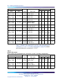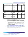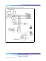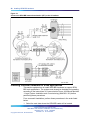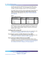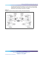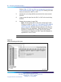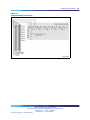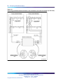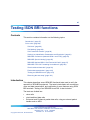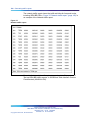
1
Nortel Communication Server 1000
ISDN Basic Rate Interface
Installation and Commissioning
NN43001-318
.
Document status: Standard
Document version: 01.02
Document date: 20 June 2007
Copyright © 2003-2007, Nortel Networks
All Rights Reserved.
Sourced in Canada
The information in this document is subject to change without notice. The statements, configurations, technical
data, and recommendations in this document are believed to be accurate and reliable, but are presented without
express or implied warranty. Users must take full responsibility for their applications of any products specified in this
document. The information in this document is proprietary to Nortel Networks.
Nortel, the Nortel Logo, the Globemark, SL-1, Meridian 1, and Succession are trademarks of Nortel Networks.
All other trademarks are the property of their respective owners.
3
Revision history
June 2007
Standard 01.02. This document is up-issued to remove the Nortel Networks
Confidential statement.
May 2007
Standard 01.01. This document is issued to support Communication Server
1000 Release 5.0. This document contains information previously contained
in the following legacy document, now retired: ISDN Basic Rate Interface:
Installation and Configuration (553-3001-218). No new content has been
added for Communication Server 1000 Release 5.0. All references to
Communication Server 1000 Release 4.5 are applicable to Communication
Server 1000 Release 5.0.
August 2005
Standard 3.00. This document is up-issued to support Communication
Server 1000 Release 4.5.
September 2004
Standard 2.00. This document is up-issued for Communication Server 1000
Release 4.0.
October 2003
Standard 1.00. This document is a new NTP for Succession 3.0. It was
created to support a restructuring of the Documentation Library, which
resulted in the merging of multiple legacy NTPs. This new document
consolidates information previously contained in the following legacy
documents, now retired:
•
ISDN Basic Rate Interface: Installation (553-3901-200)
•
ISDN Basic Rate Interface: Acceptance Testing (553-3901-330)
Nortel Communication Server 1000
ISDN Basic Rate Interface Installation and Commissioning
NN43001-318 01.02 Standard
Release 5.0 20 June 2007
Copyright © 2003-2007, Nortel Networks
.
4 Revision history
Nortel Communication Server 1000
ISDN Basic Rate Interface Installation and Commissioning
NN43001-318 01.02 Standard
Release 5.0 20 June 2007
Copyright © 2003-2007, Nortel Networks
.
5
Contents
About this document
9
Subject 9
Applicable systems 10
Intended audience 11
Conventions 11
Related information 11
Preparing for installation
Contents 13
Preparing the site 13
Unpacking and inspecting
Taking inventory 14
13
14
Installing ISDN BRI hardware
15
Contents 15
Installing ISDN BRI hardware for line applications 15
Installing ISDN BRI hardware for trunk applications 38
Preparing the system
47
Contents 47
Introduction 47
Verifying ISDN BRI operation 47
Setting up ISDN BRI test terminals and trunks 48
Configuring ISDN BRI hardware
53
Contents 53
Hardware requirements 53
Configuring ISDN BRI trunking with IP expansion cabinets or MG 1000S
systems 55
Installation procedures 56
Testing ISDN BRI functions
Contents 87
Introduction 87
Voice calls 88
Circuit-switched data calls 99
Packet data transmission 100
Nortel Communication Server 1000
ISDN Basic Rate Interface Installation and Commissioning
NN43001-318 01.02 Standard
Release 5.0 20 June 2007
Copyright © 2003-2007, Nortel Networks
.
87
6 Contents
Testing an ISDN BRI trunk 103
Removing the test setup 103
Generating traffic reports
105
Contents 105
Introduction 105
Procedures
Procedure
Procedure
Procedure
Procedure
Procedure
Procedure
Procedure
Procedure
Procedure
1
2
3
4
5
6
7
8
9
Procedure
Procedure
Procedure
Procedure
Procedure
Procedure
Procedure
Procedure
Procedure
Procedure
Procedure
Procedure
Procedure
Procedure
Procedure
Procedure
10
11
12
13
14
15
16
17
18
19
20
21
22
23
24
25
Procedure
Procedure
Procedure
Procedure
Procedure
Procedure
Procedure
Procedure
Procedure
Procedure
26
27
28
29
30
31
32
33
34
35
Procedure 36
Procedure 37
Procedure 38
Selecting the card slots 16
Remove the module cover for card installation 20
Installing the MISP 21
Removing the MISP 21
Installing the BRSC, SILC, and UILC 22
Remove the BRSC, SILC, and UILC 23
Connecting ISDN BRI terminals to the system 23
Connect the modules to the MDF 24
Cross-connecting SILC and/or UILC ports to the building
wiring 29
Connecting the ISDN BRI terminals to the DSL 36
Providing clock referencing on the SILC 39
Connecting clock reference cables 41
Performing acceptance testing 48
Selecting the card slots 58
Installing the MISP 59
Removing the MISP 60
Installing the SILCs and UILCs 61
Removing the SILC and UILC 64
Installing the PRI hardware 64
Connecting system cables to the cross-connect terminal 66
Cross-connecting the DSLs at the cross-connect terminal 70
Connecting the terminating resistor to the SILC DSL 74
Connecting the ISDN BRI terminals to the DSL 76
Initializing a Nortel Networks M5317TDX terminal 80
Connecting the system cables to the cross-connect
terminal 82
Cross-connecting DSLs at the cross-connect terminal 83
Performing a call hold test 88
Perform a Call Waiting test 89
Performing a Call Forward No Answer test 91
Perform a Calling Line Identification Presentation test 92
Perform an ISDN BRI Conference test 93
Perform a Call Join test on Conference 94
Perform a hunting test 96
Perform an ISDN BRI NI-1 Call Forward All Calls test 97
Perform an ISDN BRI ETSI Call Forwarding Unconditional
test 98
Perform a circuit-switched data call test 99
Perform a B-channel packet data transmission test using an
external packet handler 100
Perform a D-channel packet data transmission test using an
external packet handler 101
Nortel Communication Server 1000
ISDN Basic Rate Interface Installation and Commissioning
NN43001-318 01.02 Standard
Release 5.0 20 June 2007
Copyright © 2003-2007, Nortel Networks
.
Contents 7
Procedure 39
Procedure 40
Procedure 41
Perform a D-channel Switched Virtual Circuit packet data
transmission test using an MPH 101
Perform a B-channel Switched Virtual Circuit packet data
transmission test using an MPH 102
Perform procedure to test an ISDN BRI trunk DSL 103
Nortel Communication Server 1000
ISDN Basic Rate Interface Installation and Commissioning
NN43001-318 01.02 Standard
Release 5.0 20 June 2007
Copyright © 2003-2007, Nortel Networks
.
8 Contents
Nortel Communication Server 1000
ISDN Basic Rate Interface Installation and Commissioning
NN43001-318 01.02 Standard
Release 5.0 20 June 2007
Copyright © 2003-2007, Nortel Networks
.
9
About this document
This document is a global document. Contact your system supplier or your
Nortel representative to verify that the hardware and software described
are supported in your area.
Note the following:
•
ISDN Basic Rate Interface (BRI) trunking is not available in North
America.
•
The Basic Rate Signaling Concentrator (BRSC) is not supported on
CS 1000M Cabinet.
•
The integrated Meridian 1 Packet Handler is not supported on CS
1000M Cabinet.
Subject
This document contains the following information:
•
ISDN BRI hardware installation instructions for all systems
•
Description of acceptance testing of ISDN BRI services for Large
Systems, Small Systems, and CS 1000S systems.
— how to visually inspect ISDN BRI equipment for possible improper
installation
— how to interpret visual indicators on ISDN BRI cards
— how to test basic ISDN BRI features and verify traffic reporting
Note: The craftsperson conducts acceptance testing after the
equipment is installed and configured. This is done to verify that
the system is operating correctly and ISDN BRI functions and
features work as specified.
Note on legacy products and releases
This NTP contains information about systems, components, and features
that are compatible with Nortel Communication Server 1000 Release 4.5
software. For more information on legacy products and releases, click the
Technical Documentation link under Support & Training on the Nortel
home page:
Nortel Communication Server 1000
ISDN Basic Rate Interface Installation and Commissioning
NN43001-318 01.02 Standard
Release 5.0 20 June 2007
Copyright © 2003-2007, Nortel Networks
.
10 About this document
www.nortel.com
Applicable systems
This document applies to the following systems:
•
Communication Server 1000S (CS 1000S)
•
Communication Server 1000M Chassis (CS 1000M Chassis)
•
Communication Server 1000M Cabinet (CS 1000M Cabinet)
•
Communication Server 1000M Half Group (CS 1000M HG)
•
Communication Server 1000M Single Group (CS 1000M SG)
•
Communication Server 1000M Multi Group (CS 1000M MG)
•
Communication Server 1000E (CS 1000E)
Note: When upgrading software, memory upgrades may be required on
the Signaling Server, the Call Server, or both.
System migration
When particular Meridian 1 systems are upgraded to run CS 1000 Release
4.5 software and configured to include a Signaling Server, they become
CS 1000M systems. Table 1 "Meridian 1 systems to CS 1000M systems"
(page 10) lists each Meridian 1 system that supports an upgrade path to
a CS 1000M system.
Table 1
Meridian 1 systems to CS 1000M systems
This Meridian 1 system...
Maps to this CS 1000M system
Meridian 1 PBX 11C Chassis
CS 1000M Chassis
Meridian 1 PBX 11C Cabinet
CS 1000M Cabinet
Meridian 1 PBX 51C
CS 1000M Half Group
Meridian 1 PBX 61C
CS 1000M Single Group
Meridian 1 PBX 81
CS 1000M Multi Group
Meridian 1 PBX 81C
CS 1000M Multi Group
For more information, see one or more of the following NTPs:
•
Communication Server 1000M and Meridian 1 Small System Upgrade
(NN43011-459)
•
Communication Server 1000M and Meridian 1 Large System Upgrades
Overview (NN43021-458)
•
Communication Server 1000S Upgrades (NN43031-458)
•
Communication Server 1000E Upgrades (NN43041-458)
Nortel Communication Server 1000
ISDN Basic Rate Interface Installation and Commissioning
NN43001-318 01.02 Standard
Release 5.0 20 June 2007
Copyright © 2003-2007, Nortel Networks
.
Related information 11
Intended audience
This document is intended for individuals responsible for the planning,
engineering, and administration of the applicable system.
Conventions
Terminology
In this document, the following systems are referred to generically as
"system":
•
Communication Server 1000S (CS 1000S)
•
Communication Server 1000M (CS 1000M)
•
Communication Server 1000E (CS 1000E)
•
Meridian 1
The following systems are referred to generically as "Small System":
•
Communication Server 1000M Chassis (CS 1000M Chassis)
•
Communication Server 1000M Cabinet (CS 1000M Cabinet)
•
Meridian 1 PBX 11C Chassis
•
Meridian 1 PBX 11C Cabinet
The following systems are referred to generically as "Large System":
•
Communication Server 1000M Half Group (CS 1000M HG)
•
Communication Server 1000M Single Group (CS 1000M SG)
•
Communication Server 1000M Multi Group (CS 1000M MG)
•
Meridian 1 PBX 51C
•
Meridian 1 PBX 61C
•
Meridian 1 PBX 81
•
Meridian 1 PBX 81C
Related information
This section lists information sources that relate to this document.
NTPs
The following NTPs are referenced in this document:
•
Features and Services (NN43001-506)
•
Software Input Output Administration (NN43001-611)
•
Software Input Output Reference - Maintenance (NN43001-711)
Nortel Communication Server 1000
ISDN Basic Rate Interface Installation and Commissioning
NN43001-318 01.02 Standard
Release 5.0 20 June 2007
Copyright © 2003-2007, Nortel Networks
.
12 About this document
Online
To access Nortel documentation online, click the Technical Documentation
link under Support & Training on the Nortel home page:
www.nortel.com
CD-ROM
To obtain Nortel documentation on CD-ROM, contact your Nortel customer
representative.
Nortel Communication Server 1000
ISDN Basic Rate Interface Installation and Commissioning
NN43001-318 01.02 Standard
Release 5.0 20 June 2007
Copyright © 2003-2007, Nortel Networks
.
13
Preparing for installation
Contents
This section contains information on the following topics:
"Preparing the site" (page 13)
"Unpacking and inspecting" (page 14)
"Taking inventory" (page 14)
Preparing the site
When installing a system, address the following factors.
•
environmental
•
structural
•
electrical
For more information refer to Communication Server 1000M and Meridian 1
Large System Planning and Engineering (NN43021-220).
After the site has been planned, the following items must be completed
prior to ISDN BRI installation.
•
Wire the building between ISDN BRI terminal locations and the
distribution frame. Refer to the "Engineering guidelines" section of ISDN
Basic Rate Interface Feature Fundamentals (NN43001-580) for wiring
specifications and guidelines. For the location of the terminals and the
distribution frame, use the Building Cable Plan developed according
to instructions in the "Planning the site" section in Communication
Server 1000M and Meridian 1 Large System Planning and Engineering
(NN43021-220).
•
Install any Intelligent Peripheral Equipment (IPE) or Network Modules
needed to house ISDN BRI cards as determined in "Engineering
guidelines" of ISDN Basic Rate Interface Feature Fundamentals
(NN43001-580). Refer to Communication Server 1000M and Meridian
Nortel Communication Server 1000
ISDN Basic Rate Interface Installation and Commissioning
NN43001-318 01.02 Standard
Release 5.0 20 June 2007
Copyright © 2003-2007, Nortel Networks
.
14 Preparing for installation
1 Large System Installation and Commissioning (NN43021-310) for a
description of how to install the modules.
Unpacking and inspecting
ISDN BRI cards and external communication cables are shipped in separate
packages. To unpack them, follow the general precautions recommended
by computer and telephone equipment manufacturers.
•
Remove items that generate static charge from the installation site.
•
If the installation site is carpeted, spray it with an antistatic spray.
•
Ground yourself before handling any equipment.
•
Carefully remove the equipment from its packaging. Do not puncture or
tear the containers. Use scissors or a utility knife.
•
Inspect the equipment for obvious faults or damage. Report any
damaged component to your sales representative and the carrier who
delivered the equipment.
•
When unpacking the circuit cards, hold them only by their nonconductor
edges. Do not touch connector pins or components.
•
Keep the circuit cards in their antistatic bags until you are ready to
install them.
•
Do not stack the plug-in cards on top of each other. This can damage
the components and the printed circuits on the cards.
Taking inventory
After unpacking, verify that all the equipment necessary is at the site
before installation begins. Check the equipment received against the
shipping documents. Note any shortages and report them to your sales
representative.
Nortel Communication Server 1000
ISDN Basic Rate Interface Installation and Commissioning
NN43001-318 01.02 Standard
Release 5.0 20 June 2007
Copyright © 2003-2007, Nortel Networks
.
15
Installing ISDN BRI hardware
Contents
This section contains information on the following topics:
"Installing ISDN BRI hardware for line applications" (page 15)
"Installing ISDN BRI hardware for trunk applications" (page 38)
"Selecting the card slots" (page 39)
"Removing the module cover for card installation" (page 39)
"Installing the MISP" (page 39)
"Installing the clock reference on the SILC" (page 39)
"Installing the SILC and the UILC" (page 42)
"Connecting the system to the Main Distribution Frame (MDF)" (page 42)
"Cross-connecting the Main Distribution Frame (MDF)" (page 42)
"Card location forms" (page 44)
Installing ISDN BRI hardware for line applications
The following lists the procedures for installing ISDN BRI hardware for line
applications. The system must already be installed and operating according
to the instructions in Communication Server 1000M and Meridian 1 Large
System Installation and Commissioning (NN43021-310) before performing
these procedures.
For a successful installation, perform these procedures in the order listed
below:
Step
Action
1
Select the card slots where the ISDN BRI cards will be located.
2
Remove the module cover for card installation.
3
Install the Multi-Purpose ISDN Signaling Processors (MISPs).
Nortel Communication Server 1000
ISDN Basic Rate Interface Installation and Commissioning
NN43001-318 01.02 Standard
Release 5.0 20 June 2007
Copyright © 2003-2007, Nortel Networks
.
16 Installing ISDN BRI hardware
4
Install the S/T Interface Linecards (SILCs) and/or U Interface
Linecards (UILCs) or Basic Rate Signaling Concentrators (BRSCs).
5
Connect ISDN BRI terminals. This procedure comprises the
following:
•
Connect the system to the Main Distribution Frame (MDF).
•
Cross-connect the MDF.
•
Connect ISDN BRI terminals to the DSL.
•
Initialize the ISDN BRI terminals.
—End—
Procedure 1
Selecting the card slots
Step
Action
To install ISDN BRI cards, perform the following steps:
1
Identify all the slots that can contain the ISDN BRI cards. First
identify the modules with unused network and peripheral card slots
and then remove the covers from the identified modules. To identify
the modules, use the following Print Programs.
•
LD 22 to print the system configuration and identify unused
network card slots to install MISPs
•
LD 20 to list unused IPE card slots to install SILCs, UILCs and
BRSCs
Table 2 "ISDN BRI card location" (page 16) lists the modules that
can house ISDN BRI cards.
Table 2
ISDN BRI card location
SILCs,
UILCs,
BRSCs
Modules
Supported
Systems
NT4N41
Core/Network Module
Large
Systems
—
Network
slots 0-7
NT8D35
Network Module
81C CPPII
—
Network
slots 5-12
NT8D37
IPE Module
All systems
IPE slots
0-15
—
Nortel Communication Server 1000
ISDN Basic Rate Interface Installation and Commissioning
NN43001-318 01.02 Standard
Release 5.0 20 June 2007
Copyright © 2003-2007, Nortel Networks
.
MISPs
Installing ISDN BRI hardware for line applications 17
2
Locate the card slots in the modules that house ISDN BRI cards.
Group all SILCs, UILCs, BRSCs, superloops and the MISP that
supports them in the same network group to avoid using junctors
for dedicated connections.
—End—
The following rules apply when selecting the card slots:
MISPs
•
MISPs are inserted into the Core/Network Module for Large Systems
(Multi Group). Refer to the LD 22 printout to identify modules with
unused network card slots and to Table 2 "ISDN BRI card location"
(page 16) for the card slots in these modules that can house MISPs.
•
An MISP cannot share network loop addresses with a Superloop
Network Card in the Large Systems. The MISP requires two network
loop addresses and one network card slot.
•
An MISP supports a maximum of 8 BRSCs and two line cards.
•
An MISP supports a set of 4 SILCs or UILCs when not supporting a
BRSC.
•
An MISP can support both BRSCs and SILCs or UILCs at the same time.
If it serves one BRSC, an MISP can also support three line cards. If it
supports two or more BRSCs, an MISP can also support two line cards.
BRSCs
•
Install one BRSC for each IPE module.
•
With a BRSC configured, an IPE module can support a maximum of 15
line cards. These can be up to eight UILCs combined with any other
seven peripheral cards (including SILCs), or up to 15 SILCs.
SILCs/UILCs
•
The cards are installed in the Core/Network Module or the IPE Module
for all system options. Refer to the LD 20 printout to identify modules
with unused peripheral card slots.
•
In each module, install a maximum of 15 SILCs, or eight UILCs
combined with any other seven peripheral cards (including SILCs). If
15 SILCs are installed, the remaining slots in the module may contain
a BRSC, a UILCs, or non-ISDN BRI cards that do not need the - 48 V
power supply of the IPE module (this restriction is due to power supply
limitations for the module). If eight UILCs are used, you may install any
other card which could reside in the IPE module.
Nortel Communication Server 1000
ISDN Basic Rate Interface Installation and Commissioning
NN43001-318 01.02 Standard
Release 5.0 20 June 2007
Copyright © 2003-2007, Nortel Networks
.
18 Installing ISDN BRI hardware
•
Group all SILCs, UILCs, BRSCs and the MISP that supports them in the
same network group to avoid using junctors for dedicated connections.
Figures 1 through 3, beginning Figure 1 "NT8D35 Network module
(Large System)" (page 18) show typical module configurations.
Figure 1 "NT8D35 Network module (Large System)" (page 18) shows the
NT8D35 Network module.
Figure 1
NT8D35 Network module (Large System)
Figure 2 "NT8D37 IPE module (Large System)" (page 19) shows the
NT8D37 IPE module.
Nortel Communication Server 1000
ISDN Basic Rate Interface Installation and Commissioning
NN43001-318 01.02 Standard
Release 5.0 20 June 2007
Copyright © 2003-2007, Nortel Networks
.
Installing ISDN BRI hardware for line applications 19
Figure 2
NT8D37 IPE module (Large System)
Figure 3 "NT4N41 Core/Network module (Large System)" (page 19) shows
the NT4N41 Core/Network module.
Figure 3
NT4N41 Core/Network module (Large System)
Nortel Communication Server 1000
ISDN Basic Rate Interface Installation and Commissioning
NN43001-318 01.02 Standard
Release 5.0 20 June 2007
Copyright © 2003-2007, Nortel Networks
.
20 Installing ISDN BRI hardware
Procedure 2
Remove the module cover for card installation
Step
Action
To remove the covers from the modules with unused card slots, follow the
procedure below. Refer to Figure 4 "Module cover locking latches" (page
20).
1
Use a flat-blade screwdriver to unlock the left latch on the front of the
cover by turning the screw 1/4 turn clockwise.
2
Use a flat-blade screwdriver to unlock the right latch on the front of
the cover by turning the screw 1/4 turn counterclockwise.
3
While holding the cover so it does not fall off, slide the latches toward
the center of the cover.
4
Pull the cover toward you and lift it away from the module.
5
Place the cover in a safe place away from the working area to avoid
damaging it.
6
Repeat steps 1 through 5 for each cover requiring removal.
—End—
Figure 4
Module cover locking latches
Nortel Communication Server 1000
ISDN Basic Rate Interface Installation and Commissioning
NN43001-318 01.02 Standard
Release 5.0 20 June 2007
Copyright © 2003-2007, Nortel Networks
.
Installing ISDN BRI hardware for line applications 21
Procedure 3
Installing the MISP
Step
Action
Once covers have been removed and card slot locations selected for ISDN
BRI cards, install the MISP cards.
1
Hold the MISP by its card-locking devices. Squeeze the tabs to
unlatch the card-locking devices and lift the tabs out and away from
the card.
2
Insert the MISP into the selected card slot of the module so it
engages the card guides in the module.
3
Slide the MISP into the module until it engages the backplane
connector.
4
Push the MISP firmly into the connector using the locking devices as
levers by pushing them toward the card’s front panel.
5
Push the tabs firmly against the front panel of the card so they latch
to the front lip in the module and to the post on the card.
6
Observe the red LED on the MISP faceplate.
7
•
If the red LED lights and stays lit continuously without flashing
three times, the card is defective. Remove the MISP, choose a
new MISP, and repeat the installation procedure.
•
If the red LED lights, flashes three times, and turns off, the
MISP is operating correctly and is configured and enabled. Go
to step 7.
•
If it lights, flashes three times, and stays lit continuously, the
MISP is operating correctly but is not configured and enabled.
Go to step 7.
Repeat steps 1 through 6 for each MISP requiring installation.
—End—
Procedure 4
Removing the MISP
Step
Action
Perform the following steps to remove the MISP.
Nortel Communication Server 1000
ISDN Basic Rate Interface Installation and Commissioning
NN43001-318 01.02 Standard
Release 5.0 20 June 2007
Copyright © 2003-2007, Nortel Networks
.
22 Installing ISDN BRI hardware
1
Hold the MISP by its card-locking devices. Squeeze the tabs to
unlatch the card-locking devices and lift the tabs out and away from
the card.
2
Carefully remove the MISP from its card slot, and slowly slide the
card from the module.
—End—
Procedure 5
Installing the BRSC, SILC, and UILC
Step
Action
After MISPs are installed, install SILCs, UILCs, and BRSCs, as required. As
the cards are installed, keep a list of the card type (BRSC, SILC or UILC),
the module number, and the number of the card slot containing the card.
Use the Core/Network Module card location form or the IPE Module card
location form at the end of this chapter to document this information.
1
Hold the card by its card-locking devices. Squeeze the tabs to
unlatch the card-locking devices and lift them away from the card.
2
Insert the BRSC, SILC, or UILC into the selected card slot of the
module so it engages the card guides in the module.
3
Slide the BRSC, SILC, or UILC into the module until it engages the
backplane connector.
4
Push the card firmly into the connector using the locking devices as
levers by pushing them toward the card’s front panel.
5
Push the tabs firmly against the front panel of the card so they latch
to the front lip in the module and to the post on the card.
6
Observe the red LED located on the faceplate.
7
•
If the red LED turns on and stays lit continuously, the card is
defective. Remove the card, choose a new card, and repeat the
installation procedure.
•
If it flashes three times and then turns off, the card is operating
correctly. Go to step 7.
•
If the red LED flashes three times and then stays lit continuously,
the card is operating correctly but is not configured. Go to step 7.
On the CE or IPE Module card location form, fill in the card type and
the module number next to the slot number of the installed card.
Nortel Communication Server 1000
ISDN Basic Rate Interface Installation and Commissioning
NN43001-318 01.02 Standard
Release 5.0 20 June 2007
Copyright © 2003-2007, Nortel Networks
.
Installing ISDN BRI hardware for line applications 23
8
Repeat steps 1 through 7 for each card requiring installation.
—End—
Procedure 6
Remove the BRSC, SILC, and UILC
Step
Action
Perform the following steps to remove the BRSC, SILC, and the UILC.
1
Hold the card by its card-locking devices. Squeeze the tabs to
unlatch the card-locking devices and lift them away from the card.
2
Carefully disengage the BRSC, SILC, or UILC from the backplane
connector, and slowly slide the card from the module.
—End—
Procedure 7
Connecting ISDN BRI terminals to the system
Step
Action
To connect the ISDN BRI terminals to the system, perform the following
steps.
1
Connect the system to the MDF.
2
Cross-connect the MDF.
3
Connect the ISDN BRI terminals to the Digital Subscriber Line (DSL).
—End—
Figure 5 "Connect the ISDN BRI terminals to the Large System" (page
24) shows a typical DSL with ISDN BRI terminals connected to it using
modular cables.
Nortel Communication Server 1000
ISDN Basic Rate Interface Installation and Commissioning
NN43001-318 01.02 Standard
Release 5.0 20 June 2007
Copyright © 2003-2007, Nortel Networks
.
24 Installing ISDN BRI hardware
Figure 5
Connect the ISDN BRI terminals to the Large System
Procedure 8
Connect the modules to the MDF
Step
Action
Modules connect to the MDF using NE-A25B cables with 50-pin D-type male
connectors on each end. One end of the cable plugs into the Input/Output
(I/O) panel at the rear of the module, and the other end plugs into the MDF.
Nortel Communication Server 1000
ISDN Basic Rate Interface Installation and Commissioning
NN43001-318 01.02 Standard
Release 5.0 20 June 2007
Copyright © 2003-2007, Nortel Networks
.
Installing ISDN BRI hardware for line applications 25
Figure 6 "Connect the system to the MDF" (page 26) shows the cable
connection between the system and the MDF.
1
Determine the number of NE-A25B cables needed to connect one
module to the MDF.
2
Label each end of the cable specifying the module number, the
connector name (A, B, C), and the card type (SILC or UILC).
3
Plug one end of a cable into the appropriate connector on the I/O
panel at the rear of the module. Plug the other end of the cable into
the corresponding connector on the MDF.
4
Properly identify cables on the MDF. For example, plug the cable into
connector A on the I/O panel and into the connector labeled A on the
MDF, if an SILC or UILC is installed in slot 0 of an IPE module.
5
Repeat steps 2 through 4 for all cables in that module.
6
Repeat steps 1 through 5 for all modules containing SILCs and/or
UILCs.
7
Lay all the cables neatly and fasten them with cable ties.
8
Label the MDF, as necessary, using Table 3 "SILC port designations
at the MDF: NT8D37 IPE module (16-cable configuration)"
(page 27) through Table 6 "NT8D37 IPE moduleSILC and UILC
pair-terminations for connectors B, F, L, S (12-cable configuration)"
(page 33) beginning on Table 3 "SILC port designations at the MDF:
NT8D37 IPE module (16-cable configuration)" (page 27).
—End—
Nortel Communication Server 1000
ISDN Basic Rate Interface Installation and Commissioning
NN43001-318 01.02 Standard
Release 5.0 20 June 2007
Copyright © 2003-2007, Nortel Networks
.
26 Installing ISDN BRI hardware
Figure 6
Connect the system to the MDF
SILC/UILC port designations at the MDF
Table 3 "SILC port designations at the MDF: NT8D37 IPE module (16-cable
configuration)" (page 27) and Table 4 "UILC port designation labels at the
MDF: NT8D37 IPE module (16-cable configuration)" (page 27) provide
SILC/UILC port designations at the MDF for the NT8D37 IPE. Table 3 "SILC
port designations at the MDF: NT8D37 IPE module (16-cable configuration)"
(page 27) shows the SILC port designation labels for the IPE module. The
Nortel Communication Server 1000
ISDN Basic Rate Interface Installation and Commissioning
NN43001-318 01.02 Standard
Release 5.0 20 June 2007
Copyright © 2003-2007, Nortel Networks
.
Installing ISDN BRI hardware for line applications 27
UILC port designation labels for the IPE and CE modules are shown in
Table 4 "UILC port designation labels at the MDF: NT8D37 IPE module
(16-cable configuration)" (page 27).
Table 3
SILC port designations at the MDF: NT8D37 IPE module (16-cable configuration)
Table 4
UILC port designation labels at the MDF: NT8D37 IPE module (16-cable configuration)
Nortel Communication Server 1000
ISDN Basic Rate Interface Installation and Commissioning
NN43001-318 01.02 Standard
Release 5.0 20 June 2007
Copyright © 2003-2007, Nortel Networks
.
28 Installing ISDN BRI hardware
Cross-connecting the MDF
The MDF cross-connects NE-A25B cables connected to SILC and UILC
ports with building wiring connected to ISDN BRI terminals.
Nortel Communication Server 1000
ISDN Basic Rate Interface Installation and Commissioning
NN43001-318 01.02 Standard
Release 5.0 20 June 2007
Copyright © 2003-2007, Nortel Networks
.
Installing ISDN BRI hardware for line applications 29
Each SILC provides eight four-wire full-duplex ports. These ports
are connected to building wiring to form DSLs. These ports are
polarity-sensitive. Signal polarity must be maintained along each loop.
Each UILC provides eight two-wire full-duplex ports. These ports are
connected to twisted pair building wiring to form DSLs. These DSLs are
not polarity-sensitive and, although recommended, it is not necessary to
maintain signal polarity along each loop.
Procedure 9
Cross-connecting SILC and/or UILC ports to the building wiring
Step
Action
Perform the following steps to cross-connect the SILC and/or UILC ports
to the building wiring.
1
Identify the card type (SILC or UILC) for a connector on the MDF.
Refer to the IPE or CE module card location form at the end of this
chapter, which shows the card type connected to each I/O panel
connector.
2
Identify transmit and receive pairs on the top of the labeled
distribution strip for the card type and module type you are
connecting. To identify SILC or UILC ports and their pin
numbers, refer to Table 5 "NT8D37 IPE moduleSILC and UILC
pair-terminations for connectors A, E, K, R (12-cable configuration)"
(page 33) through Table 11 "Card location form: NT8D37 IPE
module (12-cable configuration)" (page 44), which begins on
Table 5 "NT8D37 IPE moduleSILC and UILC pair-terminations for
connectors A, E, K, R (12-cable configuration)" (page 33).
Note: In Table 5 "NT8D37 IPE moduleSILC and UILC
pair-terminations for connectors A, E, K, R (12-cable
configuration)" (page 33) through Table 11 "Card location
form: NT8D37 IPE module (12-cable configuration)" (page 44),
the cable pair designated T- T+ is the transmit pair and the
pair designated R+ R- is the receive pair of the S/T interface.
The cable pair designated T R is the Tx and Rx of the 2B1Q
full-duplex U interface.
3
Identify building wires connected to the bottom of the distribution
strip. Refer to the Building Cable Plan, which identifies wires
between distribution frames and wall outlets. The Building Cable
Plan is developed according to instructions in the "Planning the Site"
section in Communication Server 1000M and Meridian 1 : Large
System Planning and Engineering (553-3021-120).
4
Plug in the terminating resistor at the appropriate location in each
S/T DSL. See "Engineering Guidelines" in the ISDN Basic Rate
Nortel Communication Server 1000
ISDN Basic Rate Interface Installation and Commissioning
NN43001-318 01.02 Standard
Release 5.0 20 June 2007
Copyright © 2003-2007, Nortel Networks
.
30 Installing ISDN BRI hardware
Interface Feature Fundamentals (NN43001-580) for engineering
rules and locations of terminating resistors.
—End—
Figure 7 "Cross-connect the SILC port to the office wiring" (page 31)
and Figure 8 "Cross-connect the UILC port to the office wiring" (page
32) illustrate a cross-connection of an SILC port and an UILC port to the
building wiring.
Nortel Communication Server 1000
ISDN Basic Rate Interface Installation and Commissioning
NN43001-318 01.02 Standard
Release 5.0 20 June 2007
Copyright © 2003-2007, Nortel Networks
.
Installing ISDN BRI hardware for line applications 31
Figure 7
Cross-connect the SILC port to the office wiring
Nortel Communication Server 1000
ISDN Basic Rate Interface Installation and Commissioning
NN43001-318 01.02 Standard
Release 5.0 20 June 2007
Copyright © 2003-2007, Nortel Networks
.
32 Installing ISDN BRI hardware
Figure 8
Cross-connect the UILC port to the office wiring
Nortel Communication Server 1000
ISDN Basic Rate Interface Installation and Commissioning
NN43001-318 01.02 Standard
Release 5.0 20 June 2007
Copyright © 2003-2007, Nortel Networks
.
Installing ISDN BRI hardware for line applications 33
Table 5 "NT8D37 IPE moduleSILC and UILC pair-terminations for
connectors A, E, K, R (12-cable configuration)" (page 33) shows
pair-terminations for connectors.
Table 5
NT8D37 IPE module
SILC and UILC pair-terminations for connectors A, E, K, R (12-cable configuration)
Port signals
I/O panel connectors
Pair color
A
E
K
R
s
lot
0
slo
t4
slo
t8
s
lot
12
Card
port
SILC
UILC
Pairs
0Tx - / 0Tx +
0Rx + / 0Rx -
0T / 0R
26 / 1
27 / 2
W-BL / BL-W
W-O / O-W
1Tx - / 1Tx +
1Rx + / 1Rx -
1T / 1R
28 / 3
29 / 4
W-G / G-W
W-BR / BR-W
1
2Tx - / 2Tx +
2Rx + / 2Rx -
2T / 2R
30 / 5
31 / 6
W-S / S-W
R -BL / BL-R
2
3Tx - / 3Tx +
3Rx + / 3Rx -
3T / 3R
32 / 7
33 / 8
Rx-O / O-R
R -G / G-R
3
4Tx - / 4Tx +
4Rx + / 4Rx -
4T / 4R
34 / 9
35 / 10
R-BR / BR-R
R-S / S-R
4
5Tx - / 5Tx +
5Rx + / 5Rx -
5T / 5R
36 / 11
37 / 12
BK-BL / BL-BK
BK-O / O-BK
5
6Tx - / 6Tx +
6Rx + / 6Rx -
6T / 6R
38 / 13
39 / 14
BK-G / G-BK
BK-BR / BK-BR
6
7Tx - / 7Tx +
7Rx + / 7Rx -
7T / 7R
40 / 15
41 / 16
BK-S / S-BK
Y-BL / BL-Y
7
0
Table 6 "NT8D37 IPE moduleSILC and UILC pair-terminations for
connectors B, F, L, S (12-cable configuration)" (page 33) shows
pair-terminations for connectors B, F, L, S.
Table 6
NT8D37 IPE module
SILC and UILC pair-terminations for connectors B, F, L, S (12-cable configuration)
Port signals
I/O panel connectors
SILC
UILC
Pairs
Pair color
0Tx - / 0Tx +
0Rx + / 0Rx -
0T / 0R
26 / 1
27 / 2
W-BL / BL-W
W-O / O-W
1Tx - / 1Tx +
1Rx + / 1Rx -
1T / 1R
28 / 3
29 / 4
W-G / G-W
W-BR / BR-W
B
F
L
S
s
lot
1
slo
t5
slo
t9
s
lot
13
Nortel Communication Server 1000
ISDN Basic Rate Interface Installation and Commissioning
NN43001-318 01.02 Standard
Release 5.0 20 June 2007
Copyright © 2003-2007, Nortel Networks
.
Card
port
0
1
34 Installing ISDN BRI hardware
Port signals
I/O panel connectors
Pair color
B
F
L
UILC
Pairs
2Tx - / 2Tx +
2Rx + / 2Rx -
2T / 2R
30 / 5
31 / 6
W-S / S-W
R-BL / BL-R
2
3Tx - / 3Tx +
3Rx + / 3Rx -
3T / 3R
32 / 7
33 / 8
R-O / O-R
R-G / G-R
3
4Tx - / 4Tx +
4Rx + / 4Rx -
4T / 4R
34 / 9
35 / 10
R-BR / BR-R
R-S / S-R
4
5Tx - / 5Tx +
5Rx + / 5Rx -
5T / 5R
36 / 11
37 / 12
BK-BL / BL-BK
BK-O / O-BK
5
6Tx - / 6Tx +
6Rx + / 6Rx -
6T / 6R
38 / 13
39 / 14
BK-G / G-BK
BK-BR / BK-BR
6
7Tx - / 7Tx +
7Rx + / 7Rx -
7T / 7R
40 / 15
41 / 16
BK-S / S-BK
Y-BL / BL-Y
7
0Tx - / 0Tx +
0Rx + / 0Rx -
0T / 0R
42 / 17
43 / 18
Y-O / O-Y
Y-G / G-Y
1Tx - / 1Tx +
1Rx + / 1Rx -
1T/ 1R
44 / 19
45 / 20
Y-BR / BR-Y
Y-S / S-Y
1
2Tx - / 2Tx +
2Rx + / 2Rx -
2T / 2R
46 / 21
47 / 22
V-BL / BL-V
V-O / V-O
2
3Tx - / 3Tx +
3Rx + / 3Rx -
3T / 3R
48 / 23
49 / 24
V-G / G-V
V-BR / BR-V
3
s
lot
2
slo
t6
s
lot
10
S
Card
port
SILC
s
lot
14
0
Table 7 "NT8D37 IPE moduleSILC and UILC pair-terminations for
connectors C, G, M, T (12-cable configuration)" (page 34) shows
pair-terminations for connectors C, G, M, T.
Table 7
NT8D37 IPE module
SILC and UILC pair-terminations for connectors C, G, M, T (12-cable configuration)
Port signals
I/O panel connectors
Pair color
C
G
M
T
s
lot
2
s
lot
6
slot
10
s
lot
14
UILC
Pairs
4Tx - / 4Tx +
4Rx + / 4Rx -
4T / 4R
26 / 1
27 / 2
W-BL / BL-W
W-O / O-W
5Tx - / 5Tx +
5Rx + / 5Rx -
5T / 5R
28 / 3
29 / 4
W-G / G-W
W-BR / BR-W
5
6Tx - / 6Tx +
6Rx + / 6Rx -
6T / 6R
30 / 5
31 / 6
W-S / S-W
R-BL / BL-R
6
Nortel Communication Server 1000
ISDN Basic Rate Interface Installation and Commissioning
NN43001-318 01.02 Standard
Release 5.0 20 June 2007
Copyright © 2003-2007, Nortel Networks
.
Card
port
SILC
4
Installing ISDN BRI hardware for line applications 35
Port signals
I/O panel connectors
Pair color
C
G
M
T
Card
port
SILC
UILC
Pairs
7Tx - / 7Tx +
7Rx + / 7Rx -
7T / 7R
32 / 7
33 / 8
R-O / O-R
R-G / G-R
0Tx - / 0Tx +
0Rx + / 0Rx -
0T / 0R
34 / 9
35 / 10
R-BR / BR-R
R-S / S-R
1Tx - / 1Tx +
1Rx + / 1Rx -
1T / 1R
36 / 11
37 / 12
BK-BL / BL-BK
BK-O / O-BK
1
2Tx - / 2Tx +
2Rx + / 2Rx -
2T / 2R
38 / 13
39 / 14
BK-G / G-BK
BK-BR / BK-BR
2
3Tx - / 3Tx +
3Rx + / 3Rx -
3T / 3R
40 / 15
41 / 16
BK-S / S-BK
Y-BL / BL-Y
3
4Tx - / 4Tx +
4Rx + / 4Rx -
4T / 4R
42 / 17
43 / 18
Y-O / O-Y
Y-G / G-Y
4
5Tx - / 5Tx +
5Rx + / 5Rx -
5T / 5R
44 / 19
45 / 20
Y-BR / BR-Y
Y-S / S-Y
5
6Tx - / 6Tx +
6Rx + / 6Rx -
6T / 6R
46 / 21
47 / 22
V-BL / BL-V
V-O / V-O
6
7Tx - / 7Tx +
7Rx + / 7Rx -
7T / 7R
48 / 23
49 / 24
V-G / G-V
V-BR / BR-V
7
7
s
lot
3
s
lot
7
slot
11
s
lot
15
0
Connecting the ISDN BRI terminals to the DSL
ISDN BRI terminals are connected to DSLs using modular cables up to 10
meters (33 feet) long, with RJ-45 plugs on each end. One end of the cable
plugs into the terminal, and the other end plugs into the wall outlet.
Note: All ISDN BRI terminals should comply with CCITT, ANSI, ETSI
NET-3, INS NET-64, National ISDN, 1TR6, Numeris VN2, and D70
standards for terminals, and be compatible with the system. For a list
of compatible terminals, refer to the ISDN Basic Rate Interface Feature
Fundamentals (NN43001-580).
Figure 9 "Connect the ISDN BRI terminal to the S/T interface" (page 37)
illustrates a terminal connection to the S/T interface; Figure 10 "Connect the
ISDN BRI network termination (NT1) to the U interface" (page 38) illustrates
a network termination (NT1) connection to the U interface.
Nortel Communication Server 1000
ISDN Basic Rate Interface Installation and Commissioning
NN43001-318 01.02 Standard
Release 5.0 20 June 2007
Copyright © 2003-2007, Nortel Networks
.
36 Installing ISDN BRI hardware
Procedure 10
Connecting the ISDN BRI terminals to the DSL
Step
Action
1
Plug one end of the modular cable into the ISDN BRI interface
connector on the terminal and the other end of the modular cable
into the wall outlet.
2
For an SILC S/T interface terminal with an optional auxiliary power
source, plug the power source into the wall outlet, then plug the
cable into the power source’s RJ-45 jack. This power source must
supply power only to the local ISDN BRI terminal, not back into the
DSL through the RJ-45 wall outlet. The power adapter is supplied
with the terminal.
3
Program the terminal parameters, such as the Supervisor Position
ID (SPID) and Static Terminal Endpoint Identifier (TEI), as required
by the type of terminal. For detailed information pertaining to this
procedure, refer to the section "Initialize ISDN BRI terminals", found
in ISDN Basic Rate Interface Feature Fundamentals (NN43001-580).
4
Repeat steps 1 and 3 for each terminal to be connected.
—End—
Connecting the terminating resistors
DSLs require that a terminating resistor be connected at the end of each
loop. See ISDN Basic Rate Interface Feature Fundamentals (NN43001-580)
for engineering rules and locations of terminating resistors. The end of the
S/T interface loop has an RJ-45 jack to plug in the telephone cable. Plug
the terminating resistor into the RJ-45 jack, and then plug the telephone
cable into the terminating resistor.
Note: For every port there is one loop with only one terminating resistor
per loop. Each loop can support a maximum of eight telephones.
Nortel Communication Server 1000
ISDN Basic Rate Interface Installation and Commissioning
NN43001-318 01.02 Standard
Release 5.0 20 June 2007
Copyright © 2003-2007, Nortel Networks
.
Installing ISDN BRI hardware for line applications 37
Figure 9
Connect the ISDN BRI terminal to the S/T interface
Nortel Communication Server 1000
ISDN Basic Rate Interface Installation and Commissioning
NN43001-318 01.02 Standard
Release 5.0 20 June 2007
Copyright © 2003-2007, Nortel Networks
.
38 Installing ISDN BRI hardware
Figure 10
Connect the ISDN BRI network termination (NT1) to the U interface
Installing ISDN BRI hardware for trunk applications
This section explains how to install ISDN BRI hardware to support ISDN
BRI trunk applications. The system must already be installed and operating
according to the instructions in Communication Server 1000M and Meridian
1 Large System Installation and Commissioning (NN43021-310) before
performing these procedures.
For a successful installation, perform these procedures in the order listed
below:
1. Select the card slots where the ISDN BRI cards will be located.
Nortel Communication Server 1000
ISDN Basic Rate Interface Installation and Commissioning
NN43001-318 01.02 Standard
Release 5.0 20 June 2007
Copyright © 2003-2007, Nortel Networks
.
Installing ISDN BRI hardware for trunk applications 39
2. Install the MISP.
3. Install clock referencing on the SILC.
4. Install the SILC and/or UILC.
5. Connect the system to the MDF.
6. Cross-connect the MDF (in Terminal Equipment mode).
Note: The system, in TIE trunk or CO connectivity, requires a
different wiring configuration than for a line application; the transmit
and receive pairs should be reversed, as illustrated in Figure 12
"Connect the network termination to the U interface and to the S/T
interface (in TE mode)" (page 43).
Selecting the card slots
Follow the same procedures as described earlier for line applications (refer
to Procedure 1 "Selecting the card slots" (page 16)).
Removing the module cover for card installation
Follow the same procedures as described earlier for line applications (refer
to Procedure 2 "Remove the module cover for card installation" (page 20)).
Installing the MISP
Follow the same procedures as described for line applications (refer to
Procedure 3 "Installing the MISP" (page 21)).
Installing the clock reference on the SILC
The DSL#0 and DSL#1 on an SILC card can be configured as the reference
clock source, with DSL#0 being assigned for the primary clock reference
and DSL#1 being assigned for the secondary clock reference.
The loop number and location of the primary and secondary clock source is
configured in the Digital Data Block LD 73. Refer to the ISDN Basic Rate
Interface Feature Fundamentals (NN43001-580).
Procedure 11
Providing clock referencing on the SILC
Step
Action
Complete the following procedure to provide clock referencing on the SILC.
To install the NTRB53 Clock Controller for CS 1000 Release 4.0
refer to ISDN Primary Rate Interface Installation and Commissioning
(NN43001-301).
1
Maintain the same polarity on each transmit and receive. Rewire
the selected Tx and Rx pairs (applicable to DSL0 and DSL1) to
Nortel Communication Server 1000
ISDN Basic Rate Interface Installation and Commissioning
NN43001-318 01.02 Standard
Release 5.0 20 June 2007
Copyright © 2003-2007, Nortel Networks
.
40 Installing ISDN BRI hardware
exchange the Tx and Rx pair position. This rewiring is done at the
Main Distribution Frame (MDF).
2
Remove the phantom power jumpers (two jumpers per DSL) from
the pin headers.
3
Place the SILC in the selected IPE slot.
4
Configure the selected DSL as Terminal Equipment (TE) mode in
LD 27.
5
Enable the clock in LD 60 to output the clock references to the IPE
back plane pins.
6
Configure the Clock Controller card to accept ISDN BRI clock
reference.
7
Check the appropriate messages from the Clock Controller to ensure
that it is synchronized to the proper clock reference in LD 60).
8
Connect the ISDN BRI clock reference cables to the Clock Controller,
using the procedures which follow.
—End—
Connecting clock reference cables
Complete this procedure to connect the ISDN BRI clock reference cables
to the Clock Controller. There are three different cables that route clock
signals from the IPE back plane to the Clock Controller face plate (as shown
in Figure 11 "Clock reference cable connection" (page 41)). Refer to Table
8 "ISDN BRI clock reference tables" (page 40).
Table 8
ISDN BRI clock reference tables
Code
Length (feet)
Use
NTND70AA
1.5
Connects IPE back plane to
IPE I/O panel.
NTND71AA-AD
6.5, 12, 25, 42
Connects IPE I/O to CE I/O
panel.
NTND72AA
6.5
Connects CE I/O to Clock
Controller face plate.
Note: Measure the distance between the IPE and CE modules to
ensure that you order the correct cable lengths.
Nortel Communication Server 1000
ISDN Basic Rate Interface Installation and Commissioning
NN43001-318 01.02 Standard
Release 5.0 20 June 2007
Copyright © 2003-2007, Nortel Networks
.
Installing ISDN BRI hardware for trunk applications 41
Procedure 12
Connecting clock reference cables
Step
Action
1
Search for available D-sub 9 connector slots on the I/O panels of the
selected IPE and CE I/O modules (if the I/O panel is equipped with
D-sub 9 connector slots). If none is available, look for an empty slot
used for 25-pair wire connectors (the cables contain two adapter
plates to convert a 25-wire slot to two D-sub 9 connector slots).
2
Connect the cables as shown in Figure 11 "Clock reference cable
connection" (page 41); if choosing IPE slots 0, 4, 8, or 12, remove
the transmit and receive cable installed on pins 72 - 79 and secure
them to a proper place.
—End—
Figure 11
Clock reference cable connection
Clock recovery
The SILC is configured in the slave-slave mode when acting as a trunk
interface. This is configured through the Maintenance Signaling Channel
(MSC). The microcontroller configures the S/T chips on the SILC as
appropriate.
Nortel Communication Server 1000
ISDN Basic Rate Interface Installation and Commissioning
NN43001-318 01.02 Standard
Release 5.0 20 June 2007
Copyright © 2003-2007, Nortel Networks
.
42 Installing ISDN BRI hardware
The SILC can recover the network clock from the received data stream
using on-chip phase lock loops. The clock frequency that is recovered is
2.56 MHz. The jitter and wander conform to CCITT recommendations.
All of the S/T chips on the SILC could be configured as Terminal Equipment
Slaves (TES), but only the clocks recovered from DSL0 and DSL1 are
routed to the back plane connector pins. These clocks are provided as
differential pairs on back plane pins. See Table 9 "Clocks as differential
pairs" (page 42).
Table 9
Clocks as differential pairs
Differential pairs
Pin #
Row A
Row B
Primary
73
+Ref 0A
- Ref 0A
Primary
74
+Ref 1A
- Ref 1A
Secondary
75
+Ref 0B
- Ref 0B
Secondary
76
+Ref 1B
- Ref 1A
Automatic clock recovery is done upon the expiration of the free run guard
timer. Tracking is restored to the primary reference clock, if defined. If the
primary reference clock is disabled, tracking is restored to the secondary
reference clock, if defined.
Installing the SILC and the UILC
Follow the same procedures as described earlier for line applications (refer
to Procedure 5 "Installing the BRSC, SILC, and UILC" (page 22)).
Connecting the system to the Main Distribution Frame (MDF)
Follow the same procedures as described earlier for line applications (refer
to Procedure 8 "Connect the modules to the MDF" (page 24)).
Cross-connecting the Main Distribution Frame (MDF)
The system, in TIE trunk or CO connectivity, requires a different wiring
configuration than for a line application; the transmit and receive pairs should
be reversed, as illustrated in Figure 12 "Connect the network termination to
the U interface and to the S/T interface (in TE mode)" (page 43).
Nortel Communication Server 1000
ISDN Basic Rate Interface Installation and Commissioning
NN43001-318 01.02 Standard
Release 5.0 20 June 2007
Copyright © 2003-2007, Nortel Networks
.
Installing ISDN BRI hardware for trunk applications 43
Figure 12
Connect the network termination to the U interface and to the S/T interface (in TE mode)
Nortel Communication Server 1000
ISDN Basic Rate Interface Installation and Commissioning
NN43001-318 01.02 Standard
Release 5.0 20 June 2007
Copyright © 2003-2007, Nortel Networks
.
44 Installing ISDN BRI hardware
Card location forms
Use the following card location forms when installing SILC/UILC and BRSC
cards.
Table 10
Card location form: NT8D37 IPE module (16-cable configuration)
Card type
(SILC/UILC/BRSC)
IPE Module
number
IPE Module
slot
number
I/O panel
connector
SILC/UILC/BRSC
ports
0
A
0–7
1
B
0–7
2
C
0–7
3
D
0–7
4
E
0–7
5
F
0–7
6
G
0–7
7
H
0–7
8
K
0–7
9
L
0–7
10
M
0–7
11
N
0–7
12
R
0–7
13
S
0–7
14
T
0–7
15
U
0–7
Table 11
Card location form: NT8D37 IPE module (12-cable configuration)
Card Type
(SILC/UILC or BRSC)
IPE Module
number
IPE module
slot number
I/O panel
connector
SILC/UILC or BRSC
ports
0
A
0–7
1
B
0–7
2
B C
0–3 4–7
3
C
0–7
4
E
0–7
5
F
0–7
6
F
G
0–3
4–7
Nortel Communication Server 1000
ISDN Basic Rate Interface Installation and Commissioning
NN43001-318 01.02 Standard
Release 5.0 20 June 2007
Copyright © 2003-2007, Nortel Networks
.
Installing ISDN BRI hardware for trunk applications 45
Card Type
(SILC/UILC or BRSC)
IPE Module
number
IPE module
slot number
I/O panel
connector
SILC/UILC or BRSC
ports
7
G
0–7
8
K
0–7
9
L
0–7
10
L
M
0–3
4–7
11
M
0–7
12
R
0–7
13
S
0–7
14
S
T
0–3
4–7
Nortel Communication Server 1000
ISDN Basic Rate Interface Installation and Commissioning
NN43001-318 01.02 Standard
Release 5.0 20 June 2007
Copyright © 2003-2007, Nortel Networks
.
46 Installing ISDN BRI hardware
Nortel Communication Server 1000
ISDN Basic Rate Interface Installation and Commissioning
NN43001-318 01.02 Standard
Release 5.0 20 June 2007
Copyright © 2003-2007, Nortel Networks
.
47
Preparing the system
Contents
This section contains information on the following topics:
"Introduction" (page 47)
"Verifying ISDN BRI operation" (page 47)
"Setting up ISDN BRI test terminals and trunks" (page 48)
Introduction
This chapter describes how to prepare ISDN BRI equipment for acceptance
testing. It explains how to verify that ISDN BRI cards are enabled and
functioning correctly and how to correct any problems before starting the
test.
Verifying ISDN BRI operation
After ISDN BRI equipment has been installed and configured, you can
visually inspect ISDN BRI cards to make sure that they are operating
correctly by observing their LEDs:
•
Check the red Dis LED located on the MISP faceplate. If the Dis LED
on an MISP is lit, check that the MISP is disabled or faulty. If it is
extinguished, check that the MISP is enabled and operating. To enable
the MISP or to correct a problem, refer to ISDN Basic Rate Interface
Maintenance (NN43001-718).
•
Check the red LED located on the BRSC faceplate. If the red LED is
extinguished, check that the BRSC is enabled and operating correctly. If
the red LED is lit, check that the BRSC is manually disabled or faulty.
To enable a BRSC or to correct a problem, refer to ISDN Basic Rate
Interface Maintenance (NN43001-718).
•
Check the red LED located on the SILC and UILC faceplates. If the
red LED is extinguished, check that the SILC or UILC is enabled and
operating correctly. If the red LED is lit, check that the SILC or UILC
is manually disabled or faulty. To enable an SILC or a UILC or to
Nortel Communication Server 1000
ISDN Basic Rate Interface Installation and Commissioning
NN43001-318 01.02 Standard
Release 5.0 20 June 2007
Copyright © 2003-2007, Nortel Networks
.
48 Preparing the system
correct a problem, refer to ISDN Basic Rate Interface Maintenance
(NN43001-718).
If all indicator LEDs on ISDN BRI equipment are extinguished (with the
exception of the CC LED on an MISP), the equipment is functional and you
can set up the terminals for this test.
Setting up ISDN BRI test terminals and trunks
Set up ISDN BRI terminals
To conduct acceptance testing for ISDN BRI terminals, you must have a
setup that can verify basic ISDN BRI functions and features. Figure 13
"ISDN BRI acceptance testing setup for terminals" (page 49) shows an
example of the ISDN BRI terminal arrangement. You may wish to establish
a different test setup, which can be determined by the type of terminals
implemented in a specific customer configuration. You may want to setup
communication between ISDN BRI and non-ISDN terminals.
Refer to the ISDN Basic Rate Interface Installation and Commissioning
(NN43001-318) for ISDN BRI terminal installation instructions.
Procedure 13
Performing acceptance testing
Step
Action
To perform acceptance testing of ISDN BRI terminals:
1
Select three DSLs, two connected to different SILCs and one to
a UILC.
2
Equip each SILC DSL with two voice, one circuit-switched data, and
one low speed packet data ISDN BRI terminals.
Note: Packet data testing can be conducted only if an external
packet handler or an Meridian Packet Handler (MPH) is installed
as part of the customer configuration, and is supported by the
system (like the external DPN-100 packet handler). If packet
handler is not part of the configuration, do not equip the DSLs
with packet data terminals and skip all the packet data tests
specified in this chapter.
3
Equip the UILC DSL with a network terminator (NT1) and connect
the two voice and one circuit-switched data ISDN BRI terminal to the
S/T interface on the NT1.
4
Configure the DSLs to support these ISDN BRI terminals and
initialize the terminals as described in the "Initialize ISDN BRI
terminals" section of the ISDN Basic Rate Interface Feature
Fundamentals (NN43001-580).
Nortel Communication Server 1000
ISDN Basic Rate Interface Installation and Commissioning
NN43001-318 01.02 Standard
Release 5.0 20 June 2007
Copyright © 2003-2007, Nortel Networks
.
Setting up ISDN BRI test terminals and trunks 49
—End—
After you have completed the setup to perform acceptance testing, proceed
with the tests described in "Testing ISDN BRI functions" (page 87).
Figure 13
ISDN BRI acceptance testing setup for terminals
Set up ISDN BRI trunking - Local Exchange connectivity
Figure 14 "ISDN BRI acceptance testing setup for trunking – Local
Exchange connectivity" (page 50) illustrates a typical configuration to test
ISDN BRI Local Exchange connectivity. The ISDN BRI Local Exchange DSL
Nortel Communication Server 1000
ISDN Basic Rate Interface Installation and Commissioning
NN43001-318 01.02 Standard
Release 5.0 20 June 2007
Copyright © 2003-2007, Nortel Networks
.
50 Preparing the system
is connected to a Network Termination (NT1) device, which is physically
located on the same premises as the system. The NT1 device connects
to the Local Exchange that supports Numeris VN2, 1TR6 or D70 protocol
through a U interface. The distance limitation of the NT1 from the Local
Exchange depends on the distance supported by the Local Exchange.
To achieve system clock synchronization, configure the system as a slave
to the local exchange. Derive the clock source from either the ISDN BRI
Local Exchange connection or the other ISDN BRI/PRI/DTI local exchange
connections, if available.
After you complete the acceptance testing setup, proceed with the test
described in "Testing ISDN BRI functions" (page 87).
Figure 14
ISDN BRI acceptance testing setup for trunking - Local Exchange connectivity
Set up ISDN BRI trunking - TIE trunk connectivity
Figure 15 "ISDN BRI acceptance testing setup for trunking – TIE trunk
connectivity" (page 51) illustrates one configuration that can be used to test
ISDN BRI TIE trunk connectivity. In this configuration, a Meridian Customer
Defined Networking (MCDN) TIE trunk connection is implemented by
connecting two systems to the ISDN BRI leased line through the local
exchange using two SILC cards. The S/T interface is connected to the
local exchange using an NT1. There is no distance limitation on this
configuration. System clock synchronization can be achieved by having
Nortel Communication Server 1000
ISDN Basic Rate Interface Installation and Commissioning
NN43001-318 01.02 Standard
Release 5.0 20 June 2007
Copyright © 2003-2007, Nortel Networks
.
Setting up ISDN BRI test terminals and trunks 51
the system slave to the local exchange; the clock source may be derived
either from the ISDN BRI local exchange connections or from other ISDN
BRI/PRI/DTI local exchange connections, if available.
Figure 15
ISDN BRI acceptance testing setup for trunking - TIE trunk connectivity
Nortel Communication Server 1000
ISDN Basic Rate Interface Installation and Commissioning
NN43001-318 01.02 Standard
Release 5.0 20 June 2007
Copyright © 2003-2007, Nortel Networks
.
52 Preparing the system
Nortel Communication Server 1000
ISDN Basic Rate Interface Installation and Commissioning
NN43001-318 01.02 Standard
Release 5.0 20 June 2007
Copyright © 2003-2007, Nortel Networks
.
53
Configuring ISDN BRI hardware
Contents
This section contains information on the following topics:
"Hardware requirements" (page 53)
"Line and packet data applications" (page 53)
"ISDN BRI trunking" (page 54)
"Configuring ISDN BRI trunking with IP expansion cabinets or MG 1000S
systems" (page 55)
"Summary" (page 56)
"Installation procedures" (page 58)
Hardware requirements
This section contains the hardware requirements for:
•
line and packet data applications
•
ISDN BRI trunking
Line and packet data applications
Table 12 "Hardware requirements for line and packet data applications"
(page 53) lists the hardware required to configure line and packet data
on the system.
Table 12
Hardware requirements for line and packet data applications
Hardware
Product code
Description
MISP circuit card
NTBK22
The MISP card (NTBK22) is specific to Small
Systems and CS 1000S systems. It performs Data
Link (Layer 2) and Network (Layer 3) processing
associated with the OSI protocol.
SILC circuit card
NT6D70AA
NT6D70BA
-48V North American S/T interface line card
-40V International S/T interface line card
UILC circuit card
NT6D71
U interface line card
Nortel Communication Server 1000
ISDN Basic Rate Interface Installation and Commissioning
NN43001-318 01.02 Standard
Release 5.0 20 June 2007
Copyright © 2003-2007, Nortel Networks
.
54 Configuring ISDN BRI hardware
Hardware
Product code
Description
Terminating resistor
A0378866
Terminating resistor
PRI circuit card (one
only)
Required for packet data implementation only.
Packet handler
NTRB21
1.5Mb TMDI circuit card with built-in downloadable
D-channel
NTAK09
1.5 Mb DTI/PRI circuit card
NTAK79
2.0 Mb PRI circuit card
NTBK50
2.0 Mb PRI circuit card used with the downloadable
D-channel application
Required for packet data implementation only.
DPN-100
ISDN BRI terminals
DPN-100 packet handler is required for external
packet data implementation only when the system
does not process X.25 packets.
Required for line applications only.
M5317TDX
Proprietary terminal equipped with voice and data
transmission options and a hands-free feature;
supports B-channel and D-channel packet data.
M5000TD-1
ISDN Terminal Adapter provides a connection to
an analog telephone and supports circuit-switched
or packet data; supports B-channel and D-channel
packet data.
Any other terminal deemed compatible by Nortel
Networks.
Terminal adapters
Required if connecting non-BRI terminals to the ISDN BRI line interface.
Network termination
Required for conversion from a U to and S/T interface.
ISDN network termination unit (NT1), including NT1
standard power supply. Two cables are provided
with the NT1 power supply unit:
•
178 mm (7 in.) cable for connection between the
power supply and the NT1 unit
•
captive power cord for connection to an AC
power outlet
ISDN BRI trunking
Note: ISDN BRI trunking is not supported in North America.
Nortel Communication Server 1000
ISDN Basic Rate Interface Installation and Commissioning
NN43001-318 01.02 Standard
Release 5.0 20 June 2007
Copyright © 2003-2007, Nortel Networks
.
Configuring ISDN BRI trunking with IP expansion cabinets or MG 1000S systems
55
Table 13 "Hardware requirements for ISDN BRI trunking" (page 55) lists the
hardware required to configure ISDN BRI trunking.
Table 13
Hardware requirements for ISDN BRI trunking
Hardware
Product code
Description
MISP circuit card
NTBK22
The MISP card (NTBK22) is specific to Small
Systems and CS 1000S systems. It performs Data
Link (Layer 2) and Network (Layer 3) processing
associated with the OSI protocol.
SILC circuit card
NT6D70AA
NT6D70BA
-48V North American S/T interface line card
-40V International S/T interface line card
UILC circuit card
NT6D71
U interface line card
Clock controller
A clock controller is required in every cabinet or Media Gateway 1000S
(MG 1000S) equipped with a digital trunk card.
NTAK20AB
NTAK20BB
Network termination
Stratum 3 clock controller daughterboard
Stratum 4 clock controller daughterboard
Required for conversion from a U to and S/T interface.
ISDN network termination unit (NT1), including NT1
standard power supply. Two cables are provided
with the NT1 power supply unit:
•
178 mm (7 in.) cable for connection between the
power supply and the NT1 unit
•
captive power cord for connection to an AC
power outlet
Configuring ISDN BRI trunking with IP expansion cabinets or MG
1000S systems
Configure the MISP card slot number for ISDN BRI trunking in LD 27. Refer
to Table 14 "Correct responses to LOOP and MISP prompts in LD 27" (page
56) for the correct response to the LOOP prompt.
Nortel Communication Server 1000
ISDN Basic Rate Interface Installation and Commissioning
NN43001-318 01.02 Standard
Release 5.0 20 June 2007
Copyright © 2003-2007, Nortel Networks
.
56 Configuring ISDN BRI hardware
Configure DSL for ISDN BRI trunking in LD 27. Refer to Table 14 "Correct
responses to LOOP and MISP prompts in LD 27" (page 56) for the correct
response to the MISP prompt.
Table 14
Correct responses to LOOP and MISP prompts in LD 27
LOOP
MISP
1 – 9
1 – 9
Expansion 1
11 – 19
11 – 19
Expansion 2
21 – 29
21 – 29
Expansion 3
31 – 39
31 – 39
Expansion 4
41 – 49
41 – 49
MG 1000S 1
11 – 14
11 – 14
MG 1000S 2
21 – 24
21 – 24
MG 1000S 3
31 – 34
31 – 34
MG 1000S 4
41 – 44
41 – 44
Main
Cabinet Systems
CS 1000S and Chassis
Systems
Installation procedures
Summary
The following is a summary of the procedures to install and configure ISDN
BRI hardware. Collectively, the procedures apply to line, packet data, and
trunking applications. Individually, some procedures apply only to line,
packet data, or trunking.
Before beginning the procedures, ensure the system is installed and
operational. Perform the procedures in the order shown.
Step
Action
1
Select the card slots. See Procedure 14 "Selecting the card slots"
(page 58).
2
Remove the MISP, if previously installed. See Procedure 16
"Removing the MISP" (page 60).
3
Install the clock controller on the MISP (for trunking applications
only). "Installing the clock controller on the MISP (for trunking
applications)" (page 60)
4
Install the MISP. See Procedure 15 "Installing the MISP" (page 59).
Note 1: A clock controller is only required for ISDN BRI trunk
applications. The system supports a single active clock controller
(CC). This clock controller can support both a primary and a
Nortel Communication Server 1000
ISDN Basic Rate Interface Installation and Commissioning
NN43001-318 01.02 Standard
Release 5.0 20 June 2007
Copyright © 2003-2007, Nortel Networks
.
Installation procedures 57
secondary reference clock. These reference clock sources are
derived from either BRI spans or DSLs (DSL 0 and/or DSL 1).
Note 2: A clock controller is required in every cabinet or MG
1000S that contains a digital trunk.
5
Install the SILCs and UILCs. See Procedure 17 "Installing the SILCs
and UILCs" (page 61).
6
Remove the SILCS and UILCs, if previously installed. See Procedure
18 "Removing the SILC and UILC" (page 64).
7
Install the PRI hardware. See Procedure 19 "Installing the PRI
hardware" (page 64).
Note: This step is required for packet data implementation only.
8
Connect the ISDN BRI terminals or trunks.
a. Connect the ISDN BRI terminals for line applications:
1. Connect system cables to the cross-connect terminal.
See Procedure 20 "Connecting system cables to the
cross-connect terminal" (page 66).
2. Cross-connect the DSLs at the cross-connect terminal.
See Procedure 21 "Cross-connecting the DSLs at the
cross-connect terminal" (page 70).
3. Connect the terminating resistor to the SILC DSL. See
Procedure 22 "Connecting the terminating resistor to the
SILC DSL" (page 74).
4. Connect the ISDN BRI terminals to the DSL. See Procedure
23 "Connecting the ISDN BRI terminals to the DSL" (page
76).
5. Initialize a Nortel Networks M5317TDX terminal. See
Procedure 24 "Initializing a Nortel Networks M5317TDX
terminal" (page 80).
b. Connect the ISDN BRI trunks for trunking applications:
1. Connect the system cables to the cross-connect terminal.
See Procedure 25 "Connecting the system cables to the
cross-connect terminal" (page 82).
2. Cross-connect the DSLs at the cross-connect terminal. See
Procedure 26 "Cross-connecting DSLs at the cross-connect
terminal" (page 83).
Nortel Communication Server 1000
ISDN Basic Rate Interface Installation and Commissioning
NN43001-318 01.02 Standard
Release 5.0 20 June 2007
Copyright © 2003-2007, Nortel Networks
.
58 Configuring ISDN BRI hardware
—End—
Installation procedures
Procedure 14
Selecting the card slots
Step
Action
1
Select the appropriate ISDN BRI circuit card slot assignments
in the Small System by using Table 15 "Small System shelf slot
assignments for ISDN BRI cards" (page 58).
—End—
Table 15
Small System shelf slot assignments for ISDN BRI cards
ISDN BRI Card
MISP
(see Note 2)
SILC is not
clock reference
SILC is cloc
k reference
UILC
1-9
1-9
1-9
1-9
Expansion 1
11-19
11-19
11-19
11-19
Expansion 2
21-29
21-29
21-29
21-29
Expansion 3
31-39
31-39
31-39
31-39
Expansion 4
41-49
41-49
41-49
41-49
Main
Option
11C
Chassis
System
Note 1: For CS 1000S, physical card slots are numbered 1-4 on each MG 1000S, and 7-10 on
each MG 1000S Expansion.
Note 2: One MISP chassis supports a set of four SILCs or UILCS, or a combination of SILCs
and UILCs.
Nortel Communication Server 1000
ISDN Basic Rate Interface Installation and Commissioning
NN43001-318 01.02 Standard
Release 5.0 20 June 2007
Copyright © 2003-2007, Nortel Networks
.
Installation procedures 59
ISDN BRI Card
CS 100
0S, CS
1000M,
OPtion
11C
Chassis
MISP
(see Note 2)
SILC is not
clock reference
SILC is cloc
k reference
UILC
1-4
1-4
1-4
1-4
MG 1000S 1
11-14
11-14
11-14
11-14
MG 1000S 2
21-24
21-24
21-24
21-24
MG 1000S 3
31-34
31-34
31-34
31-34
MG 1000S 4
41-44
41-44
41-44
41-44
Expansion 1
Not
applicable
17-20
17-20
17-20
27-30
27-30
27-30
Expansion 3
37-40
37-40
37-40
Expansion 4
47-50
47-50
47-50
Call Server
Expansion 2
Note 1: For CS 1000S, physical card slots are numbered 1-4 on each MG 1000S, and 7-10 on
each MG 1000S Expansion.
Note 2: One MISP chassis supports a set of four SILCs or UILCS, or a combination of SILCs
and UILCs.
Procedure 15
Installing the MISP
Step
Action
1
Remove the cover from the system.
ATTENTION
IMPORTANT!
Wear the static discharge bracelet located inside the system before
handling circuit cards. Failure to wear the bracelet can damage the circuit
cards.
2
Remove the MISP from its shipping package and hold it by its
card-locking devices.
3
Insert the MISP into the selected card slot and lock it in place.
4
Observe the behavior of the LED on the faceplate of the MISP to
determine its status:
•
The LED lights, flashes three times and then stays lit – the MISP
is operating correctly but is not configured and enabled.
Nortel Communication Server 1000
ISDN Basic Rate Interface Installation and Commissioning
NN43001-318 01.02 Standard
Release 5.0 20 June 2007
Copyright © 2003-2007, Nortel Networks
.
60 Configuring ISDN BRI hardware
•
The LED lights, flashes three times and then turns off – indicates
the MISP is operating correctly and is configured and enabled.
•
Any other LED behavior indicates a defective MISP circuit card.
Note: The Flash ROM can become corrupted if loss of power
occurs during programming of the Flash ROM. If this occurs,
the Flash ROM automatically re-initializes when the MISP is
installed and powered up. The automatic re-initialization delays
the completion of the self-test, and it takes five minutes for the
LED to flash three times.
5
Repeat the steps for each MISP.
—End—
Procedure 16
Removing the MISP
Step
Action
1
Hold the MISP by its card-locking devices. Squeeze the tabs to
unlatch the card-locking devices and lift the tabs out and away from
the card.
2
Carefully remove the MISP from its card slot.
—End—
Installing the clock controller on the MISP (for trunking
applications)
A clock controller is only required for ISDN BRI trunk applications. The
system supports a single active clock controller. This clock controller can
support a primary and a secondary reference clock. These reference clock
sources are derived from BRI spans or DSLs (DSL 0 and/or DSL 1).
A clock controller is required in every cabinet or MG 1000S that contains a
digital trunk.
The line cards associated with BRI DSLs used as clock references are
installed in the Small System main cabinet or Media Gateway.
Use the following guidelines when installing the clock controller on the MISP:
•
If the primary reference clock source comes from a PRI or DTI, then the
clock controller is a daughterboard on the DTI/PRI card.
Nortel Communication Server 1000
ISDN Basic Rate Interface Installation and Commissioning
NN43001-318 01.02 Standard
Release 5.0 20 June 2007
Copyright © 2003-2007, Nortel Networks
.
Installation procedures 61
•
If the primary reference clock is derived from a BRI DSL, then the CC
daughterboard is on the MISP associated with that line card. DSL0 of
that line card is used to generate the reference clock.
•
To use a DTI/PRI as a secondary clock source reference, the clock
controller daughterboard must reside on a DTI, PRI, or MISP. The
clock is extracted from the target DTI/PRI span and routed to the clock
controller over the back plane.
•
To use a BRI DSL as a secondary clock source reference, the clock
controller daughterboard must reside on a DTI/PRI or an MISP. The
clock is extracted from DSL1 of the source line card and routed over
the backplane to the CC.
Procedure 17
Installing the SILCs and UILCs
Step
Action
1
Remove the cover from the assigned system.
ATTENTION
IMPORTANT!
Wear the static discharge bracelet located inside the cabinet or MG
1000S before handling circuit cards. Failure to wear the bracelet can
damage the circuit cards.
2
Remove the SILC or UILC from its shipping package and hold it by
its card locking devices.
3
Insert the SILC or UILC into the selected card slot and lock it in place.
4
Use the jumper plugs to configure the line powering options for the
SILC. Each port is equipped with its own set of option jumper plugs,
enabling individual configurations for each DSL.
The SILC has three line powering options. These options are
configured using the jumpers located near the backplane connector
as shown in Figure 16 "SILC line power options" (page 62).
Nortel Communication Server 1000
ISDN Basic Rate Interface Installation and Commissioning
NN43001-318 01.02 Standard
Release 5.0 20 June 2007
Copyright © 2003-2007, Nortel Networks
.
62 Configuring ISDN BRI hardware
Figure 16
SILC line power options
Store unused jumper plugs on position J1 of the SILC for future use.
The following are descriptions of the three options and their jumper
settings.
•
Normal power on the TX and RX leads. This option is set at
the factory and provides normal power (-48V or -40V) on the
TX lead and battery return (BRTN) on the RX lead to power the
terminal. To implement it, install one jumper plug across the RX
and BRTN pins, and one across the PWR and TX pins, as shown
in Figure 17 "Jumper plug settings for normal power on the TX
and RX leads" (page 63).
Nortel Communication Server 1000
ISDN Basic Rate Interface Installation and Commissioning
NN43001-318 01.02 Standard
Release 5.0 20 June 2007
Copyright © 2003-2007, Nortel Networks
.
Installation procedures 63
Figure 17
Jumper plug settings for normal power on the TX and RX leads
•
Reverse power on the TX and RX leads. This option is used
only in Japan and provides power (-48V or -40V) on the RX lead
and battery return (BRTN) on the TX lead to power the terminal.
To implement it, install one jumper plug across the RX and PWR
pins, and one across the BRTN and TX pins as shown in Figure
18 "Jumper plug settings for reverse power on the TX and RX
leads" (page 63).
Figure 18
Jumper plug settings for reverse power on the TX and RX leads
•
5
No power on the TX and RX leads. This option applies when
the terminal is powered locally with an adapter provided with the
terminal. It also applies when a SILC DSL is used for trunking.
Remove the jumper plugs and store them on J1 to implement
this option.
Insert the SILC or UILC into the selected card slot and lock it in place.
Nortel Communication Server 1000
ISDN Basic Rate Interface Installation and Commissioning
NN43001-318 01.02 Standard
Release 5.0 20 June 2007
Copyright © 2003-2007, Nortel Networks
.
64 Configuring ISDN BRI hardware
6
7
Observe the behaviors of the LED on the faceplate of the MISP to
determine its status:
•
The LED lights, flashes three times, and then remains lit –
indicates the card is operating correctly, but is not configured.
•
The LED lights, flashes three times, and then turns off – indicates
the card is operating correctly and is configured.
•
Any other LED behavior suggests a defective circuit card.
Repeat the steps in this procedure for each SILC or UILC being
installed.
—End—
Procedure 18
Removing the SILC and UILC
Step
Action
1
Hold the card by its card-locking devices. Squeeze the tabs to
unlatch the card-locking devices and lift them away from the card.
2
Carefully disengage the SILC or UILC from the backplane connector,
and slowly slide the card from the cabinet or MG 1000S.
—End—
Procedure 19
Installing the PRI hardware
Step
Action
This procedure is only required for packet data implementation.
1
To install the 1.5 Mb NTRB21 TMDI card or the NTAK09 1.5 Mb
PRI circuit card, refer to ISDN Primary Rate Interface Maintenance
(NN43001-717).
To install the NTAK79 2.0 Mb PRI circuit card or the NTBK50 2.0 Mb
PRI circuit card, refer to ISDN Primary Rate Interface Installation
and Commissioning (NN43001-301).
—End—
Nortel Communication Server 1000
ISDN Basic Rate Interface Installation and Commissioning
NN43001-318 01.02 Standard
Release 5.0 20 June 2007
Copyright © 2003-2007, Nortel Networks
.
Installation procedures 65
Connecting the ISDN BRI terminals (for line applications)
For line applications, five procedures are required to connect ISDN BRI
terminals to the system:
Step
Action
1
Connect system cables to the cross-connect terminal. See
Procedure 20 "Connecting system cables to the cross-connect
terminal" (page 66).
2
Cross-connect the DSLs at the cross-connect terminal. See
Procedure 21 "Cross-connecting the DSLs at the cross-connect
terminal" (page 70).
3
Connect the terminating resistor to the SILC DSL. See Procedure 22
"Connecting the terminating resistor to the SILC DSL" (page 74).
4
Connect the ISDN BRI terminals to the DSL. See Procedure 23
"Connecting the ISDN BRI terminals to the DSL" (page 76).
5
Initialize the terminals. See Procedure 24 "Initializing a Nortel
Networks M5317TDX terminal" (page 80).
—End—
Figure 19 "Connecting ISDN BRI terminals to the system" (page 66) shows
a typical DSL and multiple ISDN BRI terminals connected to the system.
Nortel Communication Server 1000
ISDN Basic Rate Interface Installation and Commissioning
NN43001-318 01.02 Standard
Release 5.0 20 June 2007
Copyright © 2003-2007, Nortel Networks
.
66 Configuring ISDN BRI hardware
Figure 19
Connecting ISDN BRI terminals to the system
Procedure 20
Connecting system cables to the cross-connect terminal
Step
Action
Each card slot equipped with a SILC or UILC requires one NE-A25B 25-pair
connector cable.
1
Remove the connector retaining bar from the connector panel in
the lower part of each cabinet. See Figure 20 "Cable connectors in
Nortel Communication Server 1000
ISDN Basic Rate Interface Installation and Commissioning
NN43001-318 01.02 Standard
Release 5.0 20 June 2007
Copyright © 2003-2007, Nortel Networks
.
Installation procedures 67
main cabinet" (page 68) and Figure 21 "Cable connectors in the
expansion cabinet" (page 68) on Figure 20 "Cable connectors in
main cabinet" (page 68), and Figure 22 "Cable connectors in the
second expansion cabinet" (page 69).
2
Connect an NE-A25B cable to each connector associated with a
card slot containing a SILC or UILC circuit card. See Figure 20
"Cable connectors in main cabinet" (page 68) and Figure 21 "Cable
connectors in the expansion cabinet" (page 68) on Figure 21 "Cable
connectors in the expansion cabinet" (page 68) and Figure 22 "Cable
connectors in the second expansion cabinet" (page 69) and Figure
23 "Back of MG 1000S cable connectors" (page 69) on Figure 23
"Back of MG 1000S cable connectors" (page 69).
Tag both ends of each cable with the cabinet or MG 1000S connector
numbers.
3
Connect the cables to the connectors at the bottom of the cabinet
or at the rear of the MG 1000S.
4
Replace the retaining bar when you connect all the cables to the
system.
5
Terminate the 25-pair cables at the cross-connect terminal.
6
Label the cross-connect terminal for each connector (UILC or SILC).
Figure 24 "SILC port designation label at the cross-connect
terminal" (page 69) and Figure 25 "UILC port designation label
at the cross-connect terminal" (page 70) on Figure 25 "UILC port
designation label at the cross-connect terminal" (page 70) show the
label used with the BIX cross-connecting system.
Note: Use of the BIX cross-connect system is not mandatory.
The system supports other cross-connect equipment. Refer to
the documentation provided with your cross-connect system for
further information.
—End—
Nortel Communication Server 1000
ISDN Basic Rate Interface Installation and Commissioning
NN43001-318 01.02 Standard
Release 5.0 20 June 2007
Copyright © 2003-2007, Nortel Networks
.
68 Configuring ISDN BRI hardware
Figure 20
Cable connectors in main cabinet
Figure 21
Cable connectors in the expansion cabinet
Nortel Communication Server 1000
ISDN Basic Rate Interface Installation and Commissioning
NN43001-318 01.02 Standard
Release 5.0 20 June 2007
Copyright © 2003-2007, Nortel Networks
.
Installation procedures 69
Figure 22
Cable connectors in the second expansion cabinet
Figure 23
Back of MG 1000S cable connectors
Figure 24
SILC port designation label at the cross-connect terminal
Note: The pair designated TX- TX+ is the transmit pair. The pair
designated RX- RX+ is the receive pair. A SILC port supplies 2 W of
Nortel Communication Server 1000
ISDN Basic Rate Interface Installation and Commissioning
NN43001-318 01.02 Standard
Release 5.0 20 June 2007
Copyright © 2003-2007, Nortel Networks
.
70 Configuring ISDN BRI hardware
power at -48 V (-40 V for Europe), simplexed over the transmit and
receive pairs. The transmit pair is negative with respect to the receive
pair.
Figure 25
UILC port designation label at the cross-connect terminal
Note: The cable pair designated T R is a 2B1Q full-duplex U interface.
Cross-connecting the DSLs Each SILC provides eight four-wire,
full-duplex ports. These ports connect to building wiring facilities to form
DSLs. Since the DSLs are polarity-sensitive, maintain signal polarity along
each loop as shown in Figure 26 "Cross-connecting a SILC port to the office
wiring" (page 73) on Figure 26 "Cross-connecting a SILC port to the office
wiring" (page 73).
Each UILC provides eight two-wire full-duplex ports. These ports connect
to twisted pair building wiring facilities to form DSLs as shown in Figure 27
"Cross-connecting a UILC port to the office wiring" (page 74) on Figure 27
"Cross-connecting a UILC port to the office wiring" (page 74). The DSLs
are not polarity-sensitive, and it is not necessary to maintain signal polarity
along each loop.
Procedure 21
Cross-connecting the DSLs at the cross-connect terminal
Step
Action
To cross-connect SILC and/or UILC ports to the building wiring:
1
Identify the card type (SILC or UILC) at the cross-connect terminal.
2
Identify the transmit and receive connections for the SILC and
the TIP and RING connections for the UILC from the label of the
distribution strip.
Refer to Table 19 "M5317TDX terminal error codes" (page 81) to
identify ports and their connections for a SILC or UILC.
3
Identify building wires connected at the cross-connect terminal.
4
Cross-connect the pins from the SILC or UILC to the building wiring.
5
Repeat this procedure for each DSL.
—End—
Nortel Communication Server 1000
ISDN Basic Rate Interface Installation and Commissioning
NN43001-318 01.02 Standard
Release 5.0 20 June 2007
Copyright © 2003-2007, Nortel Networks
.
Installation procedures 71
Table 16 "SILC and UILC port assignments connectors at cross-connect
terminal" (page 71) identifies SILC and UILC port assignments connectors
at the cross-connect terminal.
Table 16
SILC and UILC port assignments connectors at cross-connect terminal
SILC port
signals
UILC port
signals
Connector
pin number
and wire
color code
0 TX-
0T
26
W-BL
0 TX+
0R
1
BL-W
0 RX-
27
W-O
0 RX+
2
O-W
Wire
color
codes
1 TX-
1T
28
W-G
1 TX+
1R
3
G-W
1 RX-
29
W-BR
1 RX+
4
BR-W
2 TX-
2T
30
W-S
2 X+
2R
5
S-W
2 RX-
31
R-BL
2 RX+
6
BL-R
3 TX-
3T
32
R-O
3 TX+
3R
7
O-R
3 RX-
33
R-G
3 RX+
8
G-R
4 TX-
4T
34
R-BR
4 TX+
4R
9
BR-R
4 RX-
35
R-S
4 RX+
10
S-R
5 TX-
5T
36
BK-BL
5TX+
5R
11
BL-BK
5RX-
37
BK-O
5RX+
12
O-BK
Card ports
Port 0
Port 1
Port 2
Port 3
Port 4
Port 5
Note: The cable pair designated TX- TX+ is the transmit pair and the pair
designated RX+ RX- is the receive pair of the S/T interface. The cable pair
designated T R is the Tip and Ring of the 2B1Q full-duplex U interface.
Nortel Communication Server 1000
ISDN Basic Rate Interface Installation and Commissioning
NN43001-318 01.02 Standard
Release 5.0 20 June 2007
Copyright © 2003-2007, Nortel Networks
.
72 Configuring ISDN BRI hardware
SILC port
signals
UILC port
signals
Connector
pin number
and wire
color code
6 TX-
6T
38
BK-G
6 TX+
6R
13
G-BK
6 RX-
39
BK-BR
6 RX+
14
BR-BK
Wire
color
codes
7 TX-
7T
40
BK-S
7 TX+
7R
15
S-BK
7 RX-
41
Y-BL
7 RX+
16
BL-Y
Card ports
Port 6
Port 7
Note: The cable pair designated TX- TX+ is the transmit pair and the pair
designated RX+ RX- is the receive pair of the S/T interface. The cable pair
designated T R is the Tip and Ring of the 2B1Q full-duplex U interface.
Nortel Communication Server 1000
ISDN Basic Rate Interface Installation and Commissioning
NN43001-318 01.02 Standard
Release 5.0 20 June 2007
Copyright © 2003-2007, Nortel Networks
.
Installation procedures 73
Figure 26
Cross-connecting a SILC port to the office wiring
Nortel Communication Server 1000
ISDN Basic Rate Interface Installation and Commissioning
NN43001-318 01.02 Standard
Release 5.0 20 June 2007
Copyright © 2003-2007, Nortel Networks
.
74 Configuring ISDN BRI hardware
Figure 27
Cross-connecting a UILC port to the office wiring
Procedure 22
Connecting the terminating resistor to the SILC DSL
Step
Action
1
Plug the end of the SILC DSL to the RJ-45 jack on the terminating
resistor (A0378866) resistor.
—End—
Nortel Communication Server 1000
ISDN Basic Rate Interface Installation and Commissioning
NN43001-318 01.02 Standard
Release 5.0 20 June 2007
Copyright © 2003-2007, Nortel Networks
.
Installation procedures 75
Connecting the ISDN BRI terminals ISDN BRI terminals are connected
to DSLs using modular cables not longer than 10 m (33 ft) with RJ-45 type
plugs on each end. One end of the cable is plugged into the terminal, and
the other end is plugged into the telephone outlet.
All terminals must be compatible with the system and comply with one of
the following protocols for ISDN BRI terminals:
•
ETSI NET-3
•
INS NET-64
•
NUMERIS
•
ANSI standards
Contact your Nortel Networks representative for the latest list of compatible
terminals.
To connect 1TR6 terminals, an ETSI NET-3 to 1TR6 protocol converter
is required. A terminal adapter (the So-Adapter) has been specifically
designed to interface with the ISDN BRI DSL and the 1TR6 terminals. Its
main function is to convert 1TR6 protocol, sent from the 1TR6 terminal into
the ETSI NET-3 protocol required for ISDN BRI.
S/T interface specification
The S/T interface uses an 8-conductor modular cable terminated with an
8-pin RJ-45 type plug. An 8-pin RJ-45 type jack located on the terminal
connects the terminal to the DSL using this modular cable.
Table 17 "S/T interface connector specification" (page 75) shows the
connector pin assignment for the jack and the plug. It also shows the signal
names for each interface pin at the SILC and at the terminal.
Table 17
S/T interface connector specification
Pin number
RJ45 jack
pin signal name
SILC
signal name
1
Power Source 3
No connection
2
Power Source 3
No connection
3
TX +
RX +
4
RX +
TX +
5
RX -
TX -
6
TX -
RX -
7
Power Sink 2 (-)
No connection
8
Power Sink 2 (+)
No connection
Nortel Communication Server 1000
ISDN Basic Rate Interface Installation and Commissioning
NN43001-318 01.02 Standard
Release 5.0 20 June 2007
Copyright © 2003-2007, Nortel Networks
.
76 Configuring ISDN BRI hardware
Note 1: Power Source 1 (PS1): Up to 2 Watts of power is supplied by
the SILC to the terminals on the DSL. This power is simplexed over the
TX and RX pairs provided by -48 V (-40 V for Europe) supply on the
SILC. The RX pair is positive with respect to the TX pair.
Note 2: Power Sink 2 (PS2) provides an optional means of powering
the terminal from a common supply in the wiring closet.
Note 3: Power Source 3 (PS3) provides the power from the terminal to
the NT1 if the NT1 does not have a local power source.
U interface specification
The U interface uses a 2-conductor, twisted pair cable terminated with
an RJ-45 type jack. An RJ-45 type jack on the NT1 device connects the
terminal to the DSL using this twisted pair cable.
The connector pin assignments for the jack and the plug are shown in Table
18 "U interface connector specification" (page 76). The table also shows
signal names for each interface pin at the UILC and at the terminal.
Table 18
U interface connector specification
RJ45 jack
pin signal name
UILC
signal name
1
Not used
No connection
2
Not used
No connection
3
Not used
No connection
4
Tip or Ring
Tip or Ring
5
Tip or Ring
Tip or Ring
6
Not used
No connection
7
Not used
No connection
8
Not used
No connection
Pin number
Procedure 23
Connecting the ISDN BRI terminals to the DSL
Step
Action
1
Plug one end of the modular cable into the ISDN BRI interface
connector on the terminal. Plug the other end of the modular cable
into the telephone outlet.
2
If the SILC S/T interface has an optional auxiliary power source,
plug the power source into the wall outlet and then the 10-m (33-ft)
modular cable into the power source’s RJ-45 type jack.
Nortel Communication Server 1000
ISDN Basic Rate Interface Installation and Commissioning
NN43001-318 01.02 Standard
Release 5.0 20 June 2007
Copyright © 2003-2007, Nortel Networks
.
Installation procedures 77
The power source must not feed the power back into the DSL
through the RJ-45 wall outlet, only to the local ISDN BRI terminal.
The power adapter is normally supplied with the terminal.
Figure 28 "Connecting the ISDN BRI terminal to the S/T interface"
(page 78) illustrates an ISDN BRI terminal connection to an S/T
interface. Figure 29 "Connecting the ISDN network terminator to the
U interface" (page 79) illustrates an ISDN BRI terminal connection to
a U interface.
3
Enter the Static TEI at the terminal.
Note: Do not perform this step to assign Dynamic TEIs since
they are automatically assigned.
4
Enter the Service Profile ID number at the terminal.
For detailed information about this procedure, refer to the terminal
user guide.
5
Repeat step 1 to step 4 for each ISDN BRI terminal.
—End—
Nortel Communication Server 1000
ISDN Basic Rate Interface Installation and Commissioning
NN43001-318 01.02 Standard
Release 5.0 20 June 2007
Copyright © 2003-2007, Nortel Networks
.
78 Configuring ISDN BRI hardware
Figure 28
Connecting the ISDN BRI terminal to the S/T interface
Nortel Communication Server 1000
ISDN Basic Rate Interface Installation and Commissioning
NN43001-318 01.02 Standard
Release 5.0 20 June 2007
Copyright © 2003-2007, Nortel Networks
.
Installation procedures 79
Figure 29
Connecting the ISDN network terminator to the U interface
Non-BRI terminals The M5000 is Nortel Networks’s Universal
Terminal Adapter (UTA). It adapts a non-BRI data terminal or an analog
(500/2500-type) telephone to the ISDN BRI protocol. Attach a terminal to
the M5000 terminal adapter to initialize it. Refer to the M5000 terminal
adapter user guide for detailed configuration procedures.
Nortel Communication Server 1000
ISDN Basic Rate Interface Installation and Commissioning
NN43001-318 01.02 Standard
Release 5.0 20 June 2007
Copyright © 2003-2007, Nortel Networks
.
80 Configuring ISDN BRI hardware
Procedure 24
Initializing a Nortel Networks M5317TDX terminal
Step
Action
The following is an example of the steps to initialize an M5317TDX terminal.
Table 19 "M5317TDX terminal error codes" (page 81) lists and describes
error codes that can appear during terminal initialization. Additional
information is contained in the M5317TDX user guide.
1
Set the switch on the bottom of the terminal for either line power
or local power.
2
Plug in the M5317TDX terminal.
3
Press and hold down the RLS and HOLD keys as the terminal
powers up.
4
Press MAINROM.
5
Press INSTALL.
6
Press ENGLISH or FRANCAIS for your choice of language.
7
Press the soft key of the TEI you want to set PHONE, DATA or X25.
Note: Dynamic TEI is only supported with firmware version 2.0
or higher.
8
Enter * for dynamic TEI.
9
Enter the TEI on the terminal keypad for static TEI.
10
Press OK when you have finished setting the TEIs.
11
Enter the phone (voice) SPID. Press OK when finished.
12
Enter the data SPID. Press OK when finished.
13
Enter the data DN. Press OK when finished.
14
Press HEADSET until REAR displays.
15
Press SIGTYPE until MER1 displays.
16
Press A/MU until MU-LAW displays.
17
Press MORE.
18
Press DIALPLN until NATIONAL displays.
19
Press EXIT.
20
Press NO to execute SPM.
Nortel Communication Server 1000
ISDN Basic Rate Interface Installation and Commissioning
NN43001-318 01.02 Standard
Release 5.0 20 June 2007
Copyright © 2003-2007, Nortel Networks
.
Installation procedures 81
21
Press YES to enter datafill.
22
Press YES to delete existing datafill.
23
Press KEY# then use to keypad to enter the key number you want
to program.
24
Press EDIT DN then use the keypad to enter the digits of the DN.
25
Press OK then SAVE after each DN.
26
Repeat step 18 to step 25 for each voice DN keypad you want.
27
Press INSTALL and begin at step 4, If you entered incorrect data. If
the entries were correct, press EXIT.
28
Make a voice call to make sure the telephone is operational.
—End—
Table 19
M5317TDX terminal error codes
Error Code
Number
Description
>>10<<
S/T-loop sync loss and/or Frame sync loss.
>>11<<
L1 transmit timer expired.
>>21<<
Voice TEI removed by network.
>>22<<
Circuit data TEI removed by network.
>>23<<
Voice and circuit data TEI removed.
>>24<<
X25 TEI removed.
>>25<<
Voice and X25 TEI removed.
>>26<<
Circuit data and X25 TEI removed.
>>27<<
All TEI removed.
>>28<<
Voice link not established.
>>29<<
Circuit data link not established.
>>2A<<
X25 link not established.
>>2B<<
No Layer 2 link established.
>>30<<
No Layer 3 link established.
>>31<<
No valid voice SPID.
Nortel Communication Server 1000
ISDN Basic Rate Interface Installation and Commissioning
NN43001-318 01.02 Standard
Release 5.0 20 June 2007
Copyright © 2003-2007, Nortel Networks
.
82 Configuring ISDN BRI hardware
Error Code
Number
Description
>>32<<
No valid data SPID.
>>90<<
Restricted power mode in use. Lower ringer and speaker
phone volumes apply.
Connecting the ISDN BRI trunks (for trunking applications)
For trunking applications, two procedures are required to connect the ISDN
BRI trunks:
Step
Action
1
Connect the system cables to the cross-connect terminal. See
Procedure 25 "Connecting the system cables to the cross-connect
terminal" (page 82).
2
Cross-connect the DSLs at the cross-connect terminal. See
Procedure 26 "Cross-connecting DSLs at the cross-connect
terminal" (page 83).
—End—
Procedure 25
Connecting the system cables to the cross-connect terminal
Step
Action
Each card slot equipped with an SILC or UILC requires one NE-A25B
25-pair connector cable. The cables connect to the connectors at the
bottom of the cabinet or at the rear of the MG 1000S. Each connector
is assigned to its corresponding card slot (for example, connector J8 is
assigned to card slot 8).
1
Remove the connector retaining bar from the connector panel
in the lower part of each cabinet or MG 1000S. See Figure 20
"Cable connectors in main cabinet" (page 68) and Figure 21 "Cable
connectors in the expansion cabinet" (page 68) on Figure 20 "Cable
connectors in main cabinet" (page 68), and Figure 22 "Cable
connectors in the second expansion cabinet" (page 69) on Figure 22
"Cable connectors in the second expansion cabinet" (page 69).
2
Connect an NE-A25B cable to each connector associated with
a card slot containing an SILC or UILC circuit card. See Figure
20 "Cable connectors in main cabinet" (page 68) and Figure 21
"Cable connectors in the expansion cabinet" (page 68) on Figure 20
"Cable connectors in main cabinet" (page 68), and Figure 22 "Cable
Nortel Communication Server 1000
ISDN Basic Rate Interface Installation and Commissioning
NN43001-318 01.02 Standard
Release 5.0 20 June 2007
Copyright © 2003-2007, Nortel Networks
.
Installation procedures 83
connectors in the second expansion cabinet" (page 69) on Figure 22
"Cable connectors in the second expansion cabinet" (page 69).
3
Tag both ends of each cable with the cabinet or MG 1000S and
connector numbers.
4
Route cables down through the opening at the bottom of the cabinet
or MG 1000S.
5
Plug in the cables to the connector.
6
Replace the retaining bar after you have connected all cables to
the cabinet or MG 1000S.
7
Terminate the 25-pair cables at the cross-connect terminal.
8
Label the cross-connect terminal for each connector.
Figure 24 "SILC port designation label at the cross-connect
terminal" (page 69) and Figure 25 "UILC port designation label
at the cross-connect terminal" (page 70) on Figure 25 "UILC port
designation label at the cross-connect terminal" (page 70) show the
label used with the BIX cross-connecting system.
—End—
Cross-connecting DSLs Each SILC provides eight four-wire, full-duplex
ports. These ports connect to the trunk wiring facilities (typically cabling
or wiring from outside the building) to form DSLs. Since the DSLs are
polarity-sensitive, maintain signal polarity along each loop as shown
in Figure 30 "Cross-connecting an SILC port" (page 84) on Figure 30
"Cross-connecting an SILC port" (page 84).
Each UILC provides eight two-wire full-duplex ports. These ports
connect to twisted pair trunk wiring facilities to form DSLs, as shown in
Figure 31 "Cross-connecting a UILC port" (page 85). The DSLs are not
polarity-sensitive and it is not necessary to maintain signal polarity along
each loop.
Procedure 26
Cross-connecting DSLs at the cross-connect terminal
Step
Action
To cross-connect SILC and/or UILC ports to the trunk wiring facilities:
1
Identify the card type (SILC or UILC) at the cross-connect terminal.
2
Identify transmit and receive pins on the top of the labeled distribution
strip for the card type you are connecting.
Nortel Communication Server 1000
ISDN Basic Rate Interface Installation and Commissioning
NN43001-318 01.02 Standard
Release 5.0 20 June 2007
Copyright © 2003-2007, Nortel Networks
.
84 Configuring ISDN BRI hardware
Refer to Table 16 "SILC and UILC port assignments connectors at
cross-connect terminal" (page 71) on page 84 to identify ports and
their pin numbers for a SILC or UILC.
3
Identify the trunk wiring facilities connected at the cross-connect
terminal.
4
Cross-connect the pins from the SILC or UILC to the trunk wiring
facilities.
5
Repeat this procedure for each DSL.
Note: For the system DSL in TE mode, reverse the TX and
RX pairs as shown in Figure 32 "Connecting the ISDN network
terminator to the U interface and to the S/T interface (in TE
mode)" (page 86). Maintain the same polarity on the Tip and
Ring pins as for line application. Rewire the selected TX and
RX pairs to exchange their TX pairs with RX pair position.
This procedure is required since SILC cards are designed for
applications in the NT mode.
—End—
Figure 30
Cross-connecting an SILC port
Nortel Communication Server 1000
ISDN Basic Rate Interface Installation and Commissioning
NN43001-318 01.02 Standard
Release 5.0 20 June 2007
Copyright © 2003-2007, Nortel Networks
.
Installation procedures 85
Figure 31
Cross-connecting a UILC port
Nortel Communication Server 1000
ISDN Basic Rate Interface Installation and Commissioning
NN43001-318 01.02 Standard
Release 5.0 20 June 2007
Copyright © 2003-2007, Nortel Networks
.
86 Configuring ISDN BRI hardware
Figure 32
Connecting the ISDN network terminator to the U interface and to the S/T interface (in TE mode)
Nortel Communication Server 1000
ISDN Basic Rate Interface Installation and Commissioning
NN43001-318 01.02 Standard
Release 5.0 20 June 2007
Copyright © 2003-2007, Nortel Networks
.
87
Testing ISDN BRI functions
Contents
This section contains information on the following topics:
"Introduction" (page 87)
"Voice calls" (page 88)
"Call Hold" (page 88)
"Call Waiting" (page 89)
"Call Forward No Answer" (page 90)
"Calling Line Identification Presentation and Restriction" (page 91)
"ISDN BRI Conference (National ISDN-1 and ETSI)" (page 92)
"ISDN BRI Special Hunting" (page 95)
"ISDN BRI National ISDN-1 Call Forward All Calls" (page 97)
"ISDN BRI ETSI Call Forwarding Unconditional" (page 98)
"Circuit-switched data calls" (page 99)
"Packet data transmission" (page 100)
"Testing an ISDN BRI trunk" (page 103)
"Removing the test setup" (page 103)
Introduction
This chapter describes some ISDN BRI functional tests used to verify the
operation of ISDN BRI equipment. The tests include basic call connections,
voice and data transmission, and verification of some features using ISDN
BRI terminals. Testing of an ISDN BRI trunk DSL is also included.
The tests are divided into:
•
voice calls
•
circuit-switched data calls
•
B-channel and D-channel packet data calls, using an external packet
handler and an MPH
Nortel Communication Server 1000
ISDN Basic Rate Interface Installation and Commissioning
NN43001-318 01.02 Standard
Release 5.0 20 June 2007
Copyright © 2003-2007, Nortel Networks
.
88 Testing ISDN BRI functions
•
ISDN BRI trunk
Voice calls
A voice call can be established between two voice terminals across a
network (ISDN or non-ISDN), between two terminals on the same system,
and between two terminals on the same DSL. Acceptance testing of ISDN
BRI voice calls is conducted when testing the following system features
supported by ISDN BRI terminals.
•
Call Hold
•
Call Waiting
•
Call Forward No Answer
•
Calling Line Identification Presentation and Restriction
•
ISDN BRI National ISDN-1 Conference and Call Join
•
Special ISDN BRI Hunting
•
ISDN BRI ETSI Conference
•
ISDN BRI ETSI Call Forwarding Unconditional
•
ISDN BRI National ISDN-1 Call Forward All Calls
Call Hold
Call Hold is used to place an active call on hold to allow answering an
incoming call or placing an outgoing call. After releasing an incoming or an
outgoing call, retrieve the call on hold.
Note: The following test requires the terminal placing the calls on
hold to have multiple DN appearances. Otherwise, this test cannot be
performed as written.
Procedure 27
Performing a call hold test
Step
Action
1
From an ISDN BRI terminal, dial an ISDN BRI or a non-ISDN BRI
terminal and establish an active call connection.
2
Verify that voice transmission is established by talking with the
person at the other terminal.
3
Press the HOLD key to place the active call on hold.
Note: To use feature keys on different ISDN BRI terminals,
consult the user manual supplied with the terminal.
Nortel Communication Server 1000
ISDN Basic Rate Interface Installation and Commissioning
NN43001-318 01.02 Standard
Release 5.0 20 June 2007
Copyright © 2003-2007, Nortel Networks
.
Voice calls 89
4
Place an outgoing call by dialing an idle ISDN BRI or a non-ISDN
BRI terminal.
5
Complete this outgoing call and hang up.
6
Have another ISDN BRI or non-ISDN BRI terminal call while the first
call is still on hold.
7
Answer the incoming call and place it on hold.
8
Retrieve the call first held.
9
Complete the call and hang up.
10
Retrieve the second call on hold.
11
Complete the call and hang up.
—End—
This test can be repeated for terminals connected to the same DSL, different
DSLs on the same card, different DSLs on cards associated with different
MISPs/BSRCs, and between ISDN BRI and non-ISDN BRI terminals.
Call Waiting
Call Waiting informs an ISDN BRI terminal user engaged in an active call
that a call is waiting to be answered. A call setup message is sent to a DSL
when both B-channels are busy and an incoming call is in progress. This
causes a warning tone to the terminal speaker. To accept the new call, the
user must place the currently active call on hold or release the call.
Call Waiting is activated only if Hunting is not enabled or fails to handle
the incoming call. The incoming call may originate from an ISDN BRI or
a non-ISDN BRI terminal.
Note: The following test requires that the terminal receiving the second
(call waiting) call has multiple DN appearances. Otherwise, this test
will fail.
Procedure 28
Perform a Call Waiting test
Step
Action
1
Set the FEAT parameter to HTD to disable Hunting. Use LD 27
to specify this parameter when configuring the Terminal Service
Profile (TSP) for the two voice ISDN BRI DNs on one of the DSLs.
Nortel Communication Server 1000
ISDN Basic Rate Interface Installation and Commissioning
NN43001-318 01.02 Standard
Release 5.0 20 June 2007
Copyright © 2003-2007, Nortel Networks
.
90 Testing ISDN BRI functions
See "TSP configuration procedures" in ISDN Basic Rate Interface
Feature Fundamentals (NN43001-580).
2
From an ISDN BRI terminal with disabled hunting, dial another ISDN
BRI terminal and establish an active call connection.
3
From the second ISDN BRI terminal with disabled hunting, dial
another ISDN BRI terminal and establish another active call
connection. Both B-channels on the DSL are now busy.
Note: Only two ISDN BRI terminals may be on the same DSL
to allow them to connect. The other two ISDN BRIs are on a
different DSL.
4
Place an incoming call to one of the busy ISDN BRI terminals with
disabled hunting.
5
Observe the called ISDN BRI terminal. The ringing or warning tone
should sound, indicating that a call is waiting.
6
Place the active call on hold and answer the call that is waiting.
7
Complete the incoming call and hang up.
8
Retrieve the call on hold.
9
Complete the call and hang up.
—End—
Call Forward No Answer
Call Forward No Answer and Second Level Forward No Answer forwards
an unanswered call to a Call Forward No Answer Directory Number (DN)
after a predetermined number of rings. This feature is enabled at the TSP
level when defining the ISDN BRI DN. Both the external and internal Call
Forward No Answer features are configured at the DSL level using LD 27.
The call can be specified to be forwarded to the attendant, to an assigned
hunting DN, or to a flexible Call Forward No Answer DN by using LD 15.
When a call originated by an ISDN BRI terminal is forwarded to a
predetermined DN specified in LD 15, the display on that ISDN BRI terminal
is not updated to indicate a call modification.
Nortel Communication Server 1000
ISDN Basic Rate Interface Installation and Commissioning
NN43001-318 01.02 Standard
Release 5.0 20 June 2007
Copyright © 2003-2007, Nortel Networks
.
Voice calls 91
Procedure 29
Performing a Call Forward No Answer test
Step
Action
1
Set the FEAT parameter to FNA and SFA to enable Call Forward No
Answer and Second Level Forward No Answer. (SFA is needed only
to test two levels of Call Forward No Answer.) Use LD 27 to specify
these parameters when configuring the TSP for one of the two voice
ISDN BRI terminal DNs. See "TSP configuration procedures" in
ISDN Basic Rate Interface Feature Fundamentals (NN43001-580).
2
Specify the attendant as the forwarding DN using LD 15. At the
FNAL prompt, enter ATT to specify forward to attendant. Refer to
LD 15 in the Software Input Output Administration (NN43001-611)
for more details.
3
From an ISDN BRI terminal, place a call to the ISDN BRI terminal
with the enabled Call Forward No Answer feature and the specified
call forward to attendant.
4
Do not answer the call. After a predetermined number of rings, the
call is forwarded to the attendant. The display on the call-originating
ISDN BRI terminal will not be updated to indicate that the call has
been modified and forwarded to the attendant.
5
Verify the call was forwarded to the attendant by answering the
call at the attendant console. The attendant console will display
the call-originating identification number and the notification of call
redirection.
6
Hang up at the call-originating ISDN BRI terminal to release the
call connection.
—End—
Calling Line Identification Presentation and Restriction
Calling Line Identification Presentation and Restriction allows a calling party
number (Calling Line Identification) to be shown on a called party ISDN BRI
terminal display. Use LD 27 to specify this feature when configuring the TSP
for the ISDN BRI terminal DN. See "TSP configuration procedures" in ISDN
Basic Rate Interface Feature Fundamentals (NN43001-580).
Nortel Communication Server 1000
ISDN Basic Rate Interface Installation and Commissioning
NN43001-318 01.02 Standard
Release 5.0 20 June 2007
Copyright © 2003-2007, Nortel Networks
.
92 Testing ISDN BRI functions
This feature gives the calling and the called parties the option of displaying
the calling line identification as follows:
•
The called party ISDN BRI terminal must have the calling line
presentation (CLIP) parameter value set to YES to accept the calling line
identification and show it on its display.
•
If there is an option on the ISDN BRI terminal that enables the calling
party to allow or restrict the presentation of the calling line ID on a per
call basis, select the option to allow presentation. This option on the
terminal overrides the PRES parameter values entered in the TSP
data block when configuring the TSP. This depends on the telephone
configuration default. See "TSP configuration procedures" in ISDN
Basic Rate Interface Feature Fundamentals (NN43001-580).
Procedure 30
Perform a Calling Line Identification Presentation test
Step
Action
1
Configure both the calling and the called party ISDN BRI terminal
DN with CLIP = YES and PRES = YES.
2
Place a call from one terminal to the other and observe the display
on the called party ISDN BRI terminal. The Calling Line Identification
should be displayed during ringing and for the duration of the call.
3
Release the call at the called or calling party terminal.
4
Set PRES = NO in the TSP data block for the calling party ISDN BRI
terminal. If the calling party ISDN BRI terminal has an option on the
set to allow or restrict the presentation of the calling party number,
select the option to allow presentation and place a call to another
ISDN BRI terminal.
5
Observe the called party ISDN BRI terminal display. You should
see the number being displayed.
6
Release the call connection.
—End—
ISDN BRI Conference (National ISDN-1 and ETSI)
ISDN BRI Conference allows an ISDN BRI terminal user to bridge multiple
parties into a conversation. The user can:
•
invoke Conference on a call
•
add a new party to an existing call
Nortel Communication Server 1000
ISDN Basic Rate Interface Installation and Commissioning
NN43001-318 01.02 Standard
Release 5.0 20 June 2007
Copyright © 2003-2007, Nortel Networks
.
Voice calls 93
•
Call Join two separate parties on the terminal
•
disconnect from the Conference
Procedure 31
Perform an ISDN BRI Conference test
Step
Action
The same procedures can be used to test ISDN BRI NI-1 or ETSI
Conference.
1
In the DSL configuration in LD 27, set PRID = 6 to select the National
ISDN-1 protocol, or set PRID = 2 for the ETSI protocol.
2
In the TSP configuration in LD 27, define conference under FEATID:
FEATID aaa mmm <nnn>, where
aaa = A03 (3-party conference) or A06 (6-party conference)
mmm = feature activation ID (0 - 127)
nnn = feature indication ID (0 - 127) (If nnn is not entered, it is
assumed
to be the same as mmm)
3
Select National ISDN-1 or ETSI protocol on the ISDN BRI terminal if
signaling type/protocol is configurable.
4
On the ISDN BRI terminal, configure Conference. This procedure
largely depends on the implementation of feature key management
on individual terminals. In general:
a. The terminal provides Conference as a selectable feature to be
programmed on a hard/soft key. For example, on a soft key
on an M5317TDX, select FA to be FCC; on a hard key on an
M5209TDcp, select CONF.
b. The Conference key number selected on the terminal must
correspond to the feature activation ID entered for the TSP in
LD 27.
5
Configure at least two DN appearances on the ISDN BRI terminal.
On some ISDN BRI terminals, the second DN appearance allows
the user to initiate the second call.
6
Place an outgoing call from the ISDN BRI terminal.
7
After the call is established, press the Conference key. The first call
is put on hold automatically; a second key is lit to allow the user
to place the second call.
8
Place another outgoing call from the second key.
Nortel Communication Server 1000
ISDN Basic Rate Interface Installation and Commissioning
NN43001-318 01.02 Standard
Release 5.0 20 June 2007
Copyright © 2003-2007, Nortel Networks
.
94 Testing ISDN BRI functions
9
After the second call is established, press the Conference key again
to bridge the two calls. All three parties should be in a conference.
10
Press the RELEASE key to drop from the call. The ISDN BRI user
should be disconnected from the Conference; the remaining two
parties should still be connected, for two outgoing trunk calls, in
which case all parties should be disconnected.
—End—
Procedure 32
Perform a Call Join test on Conference
Step
Action
1
In the DSL configuration in LD 27, set PRID = 6 to select the National
ISDN-1 protocol, or PRID = 2 for ETSI protocol.
2
In the TSP configuration in LD 27, define conference under FEATID:
FEATID aaa mmm <nnn>, where
aaa = A03 (3-party conference) or A06 (6-party conference)
mmm = feature activation ID (0 - 127)
nnn = feature indication ID (0 - 127) (If nnn is not entered, it is
assumed to be the same as mmm)
3
On the ISDN BRI terminal, if the signaling type/protocol is
configurable, then select National ISDN-1or ETSI protocol.
4
On the ISDN BRI terminal, configure Conference. This procedure
largely depends on the implementation of feature key management
on individual terminals. In general:
a. The terminal provides Conference as a selectable feature to be
programmed on a hard/soft key. For example, on a soft key
on an M5317TDX, select FA to be FCC; on a hard key on an
M5209TDcp, select CONF.
b. The Conference key number selected on the terminal must
correspond to the feature activation ID entered for the TSP in
LD 27.
5
Configure at least two DN appearances on the ISDN BRI terminals.
On some ISDN BRI terminals, the second DN appearance is used
to allow the user to initiate the second call.
6
Place an outgoing call from the ISDN BRI terminal.
Nortel Communication Server 1000
ISDN Basic Rate Interface Installation and Commissioning
NN43001-318 01.02 Standard
Release 5.0 20 June 2007
Copyright © 2003-2007, Nortel Networks
.
Voice calls 95
7
After the first call is established, place an incoming call to the ISDN
BRI terminal.
8
Hold the first call and answer the second call.
9
Press the Conference key; the second call is put on hold.
10
Retrieve the first call and press the Conference key again. All three
parties should be in a conference.
11
Press the RELEASE key to drop from the call. The ISDN BRI user
should be disconnected from the conference; the remaining two
parties should still be connected, except for two outgoing trunk calls,
in which case all parties should be disconnected.
—End—
ISDN BRI Special Hunting
ISDN BRI Special Hunting allows a call encountering a destination that has
a call in progress to be automatically routed to a different destination in a
hunt chain. Hunting continues along a predetermined sequence of DNs in a
hunting group until an idle ISDN BRI or non-ISDN BRI terminal DN is found
or until the maximum number of hunt steps is exhausted. Use LD 27 to
define the hunting DNs in the DSL. See "DSL configuration procedures" in
ISDN Basic Rate Interface Feature Fundamentals (NN43001-580).
Special hunting for ISDN BRI supports calls terminating at an ISDN BRI
terminal. This feature is activated when a call terminating at a DSL
encounters a busy condition and if hunting is enabled. Internal and external
hunt DNs can be specified when configuring the DSL.
A busy condition occurs:
•
if the maximum number of calls on a DSL exceeds the specified limit of
calls on a DSL including active, calls held, calls waiting, and calls in
progression (as configured on LD 27), or
•
if the total number of calls including active, calls held, calls waiting, and
calls in progress exceeds the number of channels configured to handle
the incoming call type.
If the call limit on a DSL is not exceeded, an incoming call is presented to
the DSL interface as a call waiting call. If Hunting is enabled, the call will be
hunted.
Use LD 27 to enable or disable Hunting when configuring the TSP for the
ISDN BRI terminal DN. See "TSP configuration procedures" in ISDN Basic
Rate Interface Feature Fundamentals (NN43001-580).
Nortel Communication Server 1000
ISDN Basic Rate Interface Installation and Commissioning
NN43001-318 01.02 Standard
Release 5.0 20 June 2007
Copyright © 2003-2007, Nortel Networks
.
96 Testing ISDN BRI functions
Procedure 33
Perform a hunting test
Step
Action
1
Set the FEAT parameter to HTA to enable hunting for two voice ISDN
BRI terminals. Use LD 27 to specify this parameter when configuring
the TSP. See "TSP configuration procedures" in ISDN Basic Rate
Interface Feature Fundamentals (NN43001-580).
2
Use LD 27 to specify the HUNT parameter DNs when configuring
the DSL. These hunt parameter DNs specify the members of a
hunting chain. See "DSL configuration procedures" in ISDN Basic
Rate Interface Feature Fundamentals (NN43001-580).
3
Place two calls, one for each voice ISDN BRI terminal, on a DSL
to create a DSL busy condition.
4
Place a voice call to one of the busy ISDN BRI terminals with hunting
enabled. Since the channel type required to handle the incoming call
type is busy, hunting is automatically invoked to find an idle DN in
the hunting chain.
The following can occur:
•
If the call finds an idle voice ISDN BRI or non-ISDN BRI terminal,
it will ring that terminal.
•
If hunting is not successful:
— the originating party receives a busy tone if the total number
of calls on the DSL (as configured on LD 27) exceeds the
maximum number of calls allowed, or
— the call is placed in call waiting if the maximum number of
calls on the DSL is below the specified limit.
•
If the call is placed in call waiting, observe the called ISDN BRI
terminal. You should get a visual indication of the next DN and
receive an audible tone.
5
Place the active call on hold and answer the incoming call that is
waiting.
6
Complete the incoming call and hang up.
7
Retrieve the call on hold.
8
Release the call connection.
—End—
Nortel Communication Server 1000
ISDN Basic Rate Interface Installation and Commissioning
NN43001-318 01.02 Standard
Release 5.0 20 June 2007
Copyright © 2003-2007, Nortel Networks
.
Voice calls 97
ISDN BRI National ISDN-1 Call Forward All Calls
National ISDN-1 Call Forward All Calls enables a user of an ISDN BRI
terminal to have calls redirected from the user’s DN to another DN. Calls
are redirected regardless of the busy or idle status of the interface to the
user. Call Forward is assigned on the basis of the directory number and
call type (that is, the user may have voice calls forwarded, while data calls
terminate normally).
Procedure 34
Perform an ISDN BRI NI-1 Call Forward All Calls test
Step
Action
The following is to test the forwarding of a voice call from an ISDN BRI
M5317 set.
1
Set up ISDN BRI NI-1 Call Forward All Calls in LD 27 (refer to
the "Configuring ISDN BRI features" chapter in ISDN Basic Rate
Interface Feature Fundamentals (NN43001-580)).
a. Select the NI-1 protocol for the DSL.
b. Configure the Call Forward All Calls feature ID for a particular
DN and call type (enter voice call type).
2
On the ISDN BRI terminal, configure ISDN BRI National ISDN-1 Call
Forward All Calls.
3
Configure two DN appearances on the ISDN BRI terminal (use the
first DN to forward a call, and the second DN to place a call to test
the call forward). On some ISDN BRI terminals, the second DN
appearance allows the user to initiate the second call.
4
Activate ISDN BRI National ISDN-1 Call Forward All Calls on the
ISDN BRI terminal, for the first DN:
a. Press the Forward key.
b. Dial the number where calls are to be forwarded.
c. Press the Forward key.
5
From the second DN, place a call to the first DN to verify that the
call has been forwarded.
6
To cancel National ISDN-1 Call Forward All Calls, Press the Forward
or the Cancel key.
—End—
Nortel Communication Server 1000
ISDN Basic Rate Interface Installation and Commissioning
NN43001-318 01.02 Standard
Release 5.0 20 June 2007
Copyright © 2003-2007, Nortel Networks
.
98 Testing ISDN BRI functions
ISDN BRI ETSI Call Forwarding Unconditional
The ISDN BRI ETSI Call Forwarding Unconditional (CFU) supplementary
service allows an incoming call to an ISDN BRI terminal to be forwarded
to a predetermined destination, within or outside the system. The call is
forwarded whether the user is busy or idle.
An ISDN BRI user can assign the same address or a different address
for voice or data calls being forwarded. Calls can also be forwarded to an
ISDN BRI terminal or a non-ISDN BRI terminal. When the CFU feature is
activated, outgoing calls can still be made from the ISDN BRI terminal.
The ETSI supplementary service provides Call Forwarding capabilities to all
users on the access (that is, all the DNs defined under a Digital Subscriber
Loop (DSL), or an individual user (that is, a DN).
Procedure 35
Perform an ISDN BRI ETSI Call Forwarding Unconditional test
Step
Action
The following test is for forwarding a voice call from an ISDN BRI M5317 set.
1
Set up ISDN BRI ETSI Call Forwarding Unconditional in Overlay 27
(refer to the "Configuring ISDN BRI features" chapter in ISDN Basic
Rate Interface Feature Fundamentals (NN43001-580)).
a. Select the ETSI protocol for the DSL.
b. Configure the call type (enter voice call type) and Call Forward
(enter voice call forward).
2
On the ISDN BRI terminal, configure ISDN BRI ETSI Call Forward
Unconditional.
3
Configure two DN appearances on the ISDN BRI terminal (use the
first DN to forward a call, and the second DN to place a call to test
the call forward). On some ISDN BRI terminals, the second DN
appearance allows the user to initiate the second call.
4
Activate ISDN BRI ETSI Call Forwarding Unconditional on the ISDN
BRI terminal, for the first DN:
a. Press the Forward key.
b. Dial the number where calls are to be forwarded.
c. Press the Forward key.
Note: Call Forward Reminder Tone should be provided to the
ISDN BRI terminal.
5
From the second DN, place a call to the first DN, to verify that the
call ha been forwarded.
Nortel Communication Server 1000
ISDN Basic Rate Interface Installation and Commissioning
NN43001-318 01.02 Standard
Release 5.0 20 June 2007
Copyright © 2003-2007, Nortel Networks
.
Circuit-switched data calls 99
6
To cancel ISDN BRI ETSI Call Forwarding Unconditional:
a. Press the Forward or the Cancel key.
—End—
Circuit-switched data calls
A circuit-switched data call can be established between two data terminals
over a B-channel. The call is set up the same way as a voice call. Dial a call
using the ISDN BRI terminal key pad or keyboard, depending on the type of
ISDN BRI terminal used. After the connection is established and the called
ISDN BRI terminal sends an acknowledgment that it is ready to receive
data, the call-originating ISDN BRI terminal can start transmitting user data.
If the call-originating ISDN BRI terminal requests access to data stored
in another ISDN BRI or non-ISDN BRI terminal, it may have to provide a
password to be able to access that data.
Note: Follow the instructions in the ISDN BRI terminal user manual for
a detailed description of how to set up a call connection and how to
transmit and receive data.
In general, data terminals are divided into the following categories:
•
intelligent terminals, such as personal computers
•
dumb terminals such as video display terminals
Repeat this test on several terminals, including both intelligent and dumb
terminals as needed.
Procedure 36
Perform a circuit-switched data call test
Step
Action
1
From an ISDN BRI data terminal, dial another ISDN BRI data
terminal and establish an active call connection.
2
After receiving an acknowledgment that the other terminal is ready,
begin transmitting data.
3
Verify that the transmitted data has been received successfully by
checking transmitted information for accuracy. Read the information
on the screen or print it on the local printer.
4
Release the connection.
—End—
Nortel Communication Server 1000
ISDN Basic Rate Interface Installation and Commissioning
NN43001-318 01.02 Standard
Release 5.0 20 June 2007
Copyright © 2003-2007, Nortel Networks
.
100 Testing ISDN BRI functions
Packet data transmission
A packet data call can be established between two data terminals over a
B-channel or a D-channel.
B-channel packet data terminals communicate with the packet handler at 64
kbps over dedicated B-channels. The packet handler may be an external
packet handler, the DPN-100, or the integrated MPH. The packet handlers
processes and distributes the data to local terminals for local calls or over
the packet data network for remote calls.
D-channel packet data terminals communicate at a baud rate of up to 9.6
kbps. The packet data is multiplexed onto a 64 kbps BD that is linked with
the external packet handler through a dedicated ISDN PRI B-channel, or, in
the case of the MPH, through a dedicated connection.
Note: To perform packet data transmission verification, the system
must be connected to a DPN-100, or configured with MPH. Also, packet
data transmission functions must be selected when configuring the
B-channel and D-channel transmission characteristics. Use LD 27 to
specify the packet data transmission functions. See "MISP configuration
procedures" in ISDN Basic Rate Interface Feature Fundamentals
(NN43001-580).
In addition to configuring the MISP and the DSL in LD 27, ensure the
following:
•
the ISDN PRI loop carrying packet data was configured in LD 17
•
the packet handler route was specified in LD 16
•
an ISDN PRI channel for the packet handler route was configured using
LD 14
See ISDN Basic Rate Interface Feature Fundamentals (NN43001-580) for
a detailed description of how to configure relevant ISDN BRI packet data
transmission parameters in LD 17, LD 16, and LD 14.
Procedure 37
Perform a B-channel packet data transmission test using an external packet
handler
Step
Action
1
From an ISDN BRI B-channel packet data terminal, dial another
local or a remote ISDN BRI packet data terminal and establish an
active call connection.
After the call-originating ISDN BRI terminal receives an
Nortel Communication Server 1000
ISDN Basic Rate Interface Installation and Commissioning
NN43001-318 01.02 Standard
Release 5.0 20 June 2007
Copyright © 2003-2007, Nortel Networks
.
Packet data transmission
101
acknowledgment that the receiving ISDN BRI terminal is ready, the
call-originating ISDN BRI terminal can begin transmitting packet
data.
2
Verify that the transmitted data has been received successfully
by checking the transmitted information for accuracy. Read the
information on the screen or print it on the local printer.
3
Release the connection.
—End—
Repeat this test on other ISDN BRI packet data terminals as needed.
Procedure 38
Perform a D-channel packet data transmission test using an external packet
handler
Step
Action
1
From an ISDN BRI D-channel packet data terminal, dial another
ISDN BRI packet data terminal and establish an active call
connection.
After the call-originating ISDN BRI terminal receives an
acknowledgment that the receiving ISDN BRI terminal is ready,
the call-originating ISDN BRI terminal can begin transmitting
packet data.
2
Verify that the transmitted data has been received successfully
by checking the transmitted information for accuracy. Read the
information on the screen or print it on the local printer.
3
Release the connection.
—End—
Procedure 39
Perform a D-channel Switched Virtual Circuit packet data transmission test
using an MPH
Step
Action
1
From an ISDN BRI D-channel packet data terminal, dial another local
ISDN BRI packet data terminal or a remote packet data terminal
(depending on how you have configured your MPH application).
Establish an active call connection.
Nortel Communication Server 1000
ISDN Basic Rate Interface Installation and Commissioning
NN43001-318 01.02 Standard
Release 5.0 20 June 2007
Copyright © 2003-2007, Nortel Networks
.
102 Testing ISDN BRI functions
2
After the call-originating ISDN BRI terminal receives an
acknowledgment that the receiving ISDN BRI terminal is ready, the
call-originating ISDN BRI terminal can begin transmitting packet
data.
3
Verify that the transmitted data has been received successfully
by checking the transmitted information for accuracy. Read the
information on the screen or print it on the local printer.
4
Perform this test between two ISDN BRI terminals on the same MPH
for local transmission and between a system ISDN BRI terminal
and a remote ISDN BRI terminal over the Packet Switched Data
Network (PSDN).
5
Release the connection.
—End—
Procedure 40
Perform a B-channel Switched Virtual Circuit packet data transmission test
using an MPH
Step
Action
1
From an ISDN BRI B-channel packet data terminal, dial the Network
Terminal Numbers (NTNs) as configured in LD 27. Establish an
active call connection.
2
After the call-originating ISDN BRI terminal receives an
acknowledgment that the receiving ISDN BRI terminal is ready, the
call originating ISDN BRI terminal can begin transmitting packet data.
3
Verify that the transmitted data has been received successfully
by checking the transmitted information for accuracy. Read the
information on the screen or print it on the local printer.
4
Perform this test between two ISDN BRI terminals on the same MPH
for local transmission and between a system ISDN BRI terminal and
a remote ISDN BRI terminal over the packet data network.
5
Release the connection.
—End—
Nortel Communication Server 1000
ISDN Basic Rate Interface Installation and Commissioning
NN43001-318 01.02 Standard
Release 5.0 20 June 2007
Copyright © 2003-2007, Nortel Networks
.
Removing the test setup 103
Testing an ISDN BRI trunk
Procedure 41
Perform procedure to test an ISDN BRI trunk DSL
Step
Action
1
Set up the ISDN trunk test configuration to be used, as described
previously in the chapter "Set up ISDN BRI test terminals and
trunks".
2
Place a call across the ISDN BRI trunk.
3
Complete the call and hang up.
—End—
Removing the test setup
After acceptance testing has been completed and the results show the
system is operating correctly, remove the ISDN BRI terminal setup and
configure ISDN BRI equipment according to the customer configuration.
If the actual customer configuration was used to perform these tests, no
changes are needed.
Nortel Communication Server 1000
ISDN Basic Rate Interface Installation and Commissioning
NN43001-318 01.02 Standard
Release 5.0 20 June 2007
Copyright © 2003-2007, Nortel Networks
.
104 Testing ISDN BRI functions
Nortel Communication Server 1000
ISDN Basic Rate Interface Installation and Commissioning
NN43001-318 01.02 Standard
Release 5.0 20 June 2007
Copyright © 2003-2007, Nortel Networks
.
105
Generating traffic reports
Contents
This section contains information on the following topics:
"Introduction" (page 105)
Introduction
This chapter describes how to generate traffic reports to verify that the traffic
generated during voice and data transmission testing has been stored by
the system and can be printed on demand. To verify traffic generated during
acceptance testing, use the following command:
INVS (options)*
The asterisk (*) denotes that the ENTER key must be pressed after the
desired option numbers are entered.
Reports are generated using one or more of the following option numbers.
Meaning
Option
1
Network traffic report
11
ISDN BRI MISP and/or BRSC traffic report
12
ISDN BRI MISP and/or BRSC D-channel management
messages report
13
ISDN BRI MISP and/or BRSC messages report
14
Trunk DSL system traffic report
15
MPH traffic report
For example, to verify ISDN BRI traffic generated during acceptance testing,
select the network traffic report and the MISP traffic report as follows:
INVS 1 11
The system printer should print these two reports. Check the reports to
make sure the traffic generated during the test is reflected in the reports.
Nortel Communication Server 1000
ISDN Basic Rate Interface Installation and Commissioning
NN43001-318 01.02 Standard
Release 5.0 20 June 2007
Copyright © 2003-2007, Nortel Networks
.
106 Generating traffic reports
The network traffic report shows the traffic activities for lines and trunks,
including ISDN BRI DSLs. Figure 33 "Network traffic report" (page 106) is
an example of the Network traffic report.
Figure 33
Network traffic report
For a detailed description of how to set up and print traffic reports, see
"Set up ISDN BRI traffic reports" in ISDN Basic Rate Interface Feature
Fundamentals (NN43001-580).
Nortel Communication Server 1000
ISDN Basic Rate Interface Installation and Commissioning
NN43001-318 01.02 Standard
Release 5.0 20 June 2007
Copyright © 2003-2007, Nortel Networks
.
Nortel Communication Server 1000
ISDN Basic Rate Interface Installation and Commissioning
Copyright © 2003-2007, Nortel Networks
All Rights Reserved.
Publication: NN43001-318
Document status: Standard
Document version: 01.02
Document date: 20 June 2007
To provide feedback or to report a problem with this document, go to www.nortel.com/documentfeedback.
Sourced in Canada.
The information in this document is subject to change without notice. The statements, configurations, technical data, and
recommendations in this document are believed to be accurate and reliable, but are presented without express or implied
warranty. Users must take full responsibility for their applications of any products specified in this document. The information in
this document is proprietary to Nortel Networks.
Nortel, the Nortel Logo, the Globemark, SL-1, Meridian1, and Succession are trademarks of Nortel Networks.
All other trademarks are the property of their respective owners.