1
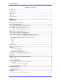
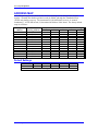
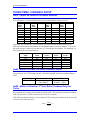
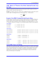
^1 USER MANUAL
^2 Accessory 8D Option 9
^3 Yaskawa Absolute Encoder Converter Board
^4 3A9-0ACC8D-xUxx
^5 October 27, 2003
Single Source Machine Control
Power // Flexibility // Ease of Use
21314 Lassen Street Chatsworth, CA 91311 // Tel. (818) 998-2095 Fax. (818) 998-7807 // www.deltatau.com
Copyright Information
© 2003 Delta Tau Data Systems, Inc. All rights reserved.
This document is furnished for the customers of Delta Tau Data Systems, Inc. Other uses are
unauthorized without written permission of Delta Tau Data Systems, Inc. Information contained in
this manual may be updated from time-to-time due to product improvements, etc., and may not
conform in every respect to former issues.
To report errors or inconsistencies, call or email:
Delta Tau Data Systems, Inc. Technical Support
Phone: (818) 717-5656
Fax: (818) 998-7807
Email: [email protected]
Website: http://www.deltatau.com
Operating Conditions
All Delta Tau Data Systems, Inc. motion controller products, accessories, and amplifiers contain
static sensitive components that can be damaged by incorrect handling. When installing or handling
Delta Tau Data Systems, Inc. products, avoid contact with highly insulated materials. Only
qualified personnel should be allowed to handle this equipment.
In the case of industrial applications, we expect our products to be protected from hazardous or
conductive materials and/or environments that could cause harm to the controller by damaging
components or causing electrical shorts. When our products are used in an industrial environment,
install them into an industrial electrical cabinet or industrial PC to protect them from excessive or
corrosive moisture, abnormal ambient temperatures, and conductive materials. If Delta Tau Data
Systems, Inc. products are directly exposed to hazardous or conductive materials and/or
environments, we cannot guarantee their operation.
Accessory 8D Option 9
Table of Contents
INTRODUCTION ........................................................................................................................................ 1
CONNECTORS............................................................................................................................................ 3
JP1 to JP4 ................................................................................................................................................... 3
JP6.............................................................................................................................................................. 3
JP7.............................................................................................................................................................. 3
JENC1 to JENC4........................................................................................................................................ 3
JP8.............................................................................................................................................................. 3
ADDRESS MAP ........................................................................................................................................... 5
Default Settings.......................................................................................................................................... 5
ABSOLUTE ENCODER SETUP................................................................................................................ 7
PMAC I-VARIABLE SETUP ..................................................................................................................... 9
Ix10 - Motor x Power-On Servo Position Address .................................................................................... 9
I8x - Motor x Resolver Gear Ratio........................................................................................................... 10
I9x - Motor x Second -Resolver Gear Ratio............................................................................................. 10
Ix81 - Motor x Absolute Phasing Position Address ................................................................................. 10
TURBO PMAC I-VARIABLE SETUP .................................................................................................... 11
Ixx10 – Motor xx Power-On Position Address ........................................................................................ 11
Ixx95 - Motor xx Power-On Servo Position Format ................................................................................ 11
Ixx98 - Motor xx Resolver 3rd Gear Ratio (Yaskawa Only) for Turbo .................................................... 11
Ixx99 - Motor xx 2nd Resolver Gear Ratio (Yaskawa Encoder only) for Turbo ...................................... 12
Example: Turbo PMAC Yaskawa Absolute Encoder Setup ................................................................. 12
Turbo PMAC Power On Phasing ............................................................................................................. 12
Ixx81 .................................................................................................................................................... 13
Ixx91 .................................................................................................................................................... 13
Ixx75 .................................................................................................................................................... 14
Ixx80 .................................................................................................................................................... 14
JUMPER SETUP ....................................................................................................................................... 15
CONNECTOR PINOUTS ......................................................................................................................... 17
Headers..................................................................................................................................................... 17
JP1 to JP4 (20-Pin Header) ................................................................................................................ 17
JP6 and JP7 (26-Pin Header) ............................................................................................................. 18
JENC1 to JENC4 (10-Pin Header)...................................................................................................... 18
SERVOPACK 1CN TERMINAL DESCRIPTION................................................................................. 19
TEST SETUP.............................................................................................................................................. 21
YASKAWA ABSOLUTE ENCODER INTERFACE ............................................................................. 23
Jumper Settings ........................................................................................................................................ 23
Jumper E8 & E9 Setup ........................................................................................................................ 23
PMAC I-Variable Setup ........................................................................................................................... 23
Ix10 - Power-On Initial Position Type and Address: .......................................................................... 23
I8x and I9x:.......................................................................................................................................... 24
Ix81 - Motor x Absolute Phasing Address:.......................................................................................... 24
MI11x (Bit 16-23 only-first two digits) ................................................................................................ 24
TROUBLE SHOOTING............................................................................................................................ 25
Data Acquisition Sequence ...................................................................................................................... 25
Checking Up Steps................................................................................................................................... 25
APPENDIX ................................................................................................................................................. 27
Setup Method for 12-bit Absolute Encoder.............................................................................................. 27
Table of Contents
i
Accessory 8D Option 9
ii
Table of Contents
Accessory 8D Option 9
INTRODUCTION
PMAC’s Accessory 8D Option 9 (P/N 309-0ACC8D-OPT9) allows a PMAC interface to the
YASKAWA absolute encoder.
This board provides up to 4 channels of absolute encoder inputs to the PMAC controller with
both A/B quadrature incremental encoder signal feedback as well as absolute position data. To
prevent data from being lost in the case of power loss or power off conditions, a 3V battery is
included on the board with a monitor circuit to provide an indication of any drop in excess of 5%.
In addition, there are four jumpers on the board to allow the customer to reset the absolute
position value. See the related paragraphs below for a detailed description of the absolute encoder
setup.
The encoder has internal counters and memory that count and retain the incremental counts.
Upon power up, it sends RS232 data to PMAC representing the absolute position. Operation is
then automatically switched to incremental. Refer to the YASKAWA manual for further
explanation.
Note
If you are using a PMAC with Flash Memory (40 MHz or 60 MHz), you must
use firmware version 1.16A or newer. Call the factory for details on upgrading
your firmware.
Introduction
1
Accessory 8D Option 9
2
Introduction
Accessory 8D Option 9
CONNECTORS
JP1 to JP4
These connectors are 20-pin Honda connectors that come directly from the absolute encoder. For
detail signal description, refer to the YASKAWA manual.
JP6
This is a 26-pin header that provides the link between PMAC’s JTHW (J3) and the absolute
encoder conversion board through the supplied flat cable. Through this connector, PMAC
captures the absolute position.
JP7
This is a 26-pin header, which brings out the JTHW signals for the next accessory board on the
JTHW multiplex memory map. This connector is pin-to-pin compatible with JP6.
JENC1 to JENC4
These are 10-pin headers that provide the normal differential A quad B encoder signal as well as
a C channel generated by the absolute encoder. The four connectors are for the first to the fourth
encoder, respectively.
JP8
This is a 2-pin terminal block for the power supply input. The power requirement of the system
is +5V DC @ 10W. External power is needed only when JP6 or JP7 and JENC1-JENC4 are not
connected.
Connectors
3
Accessory 8D Option 9
4
Connectors
Accessory 8D Option 9
ADDRESS MAP
ACC-8D Option 9 generates both absolute and incremental position data from the absolute
encoder. Normally the absolute position is read (by PMAC) through the Thumbwheel Port
(JTHW) only during power up. The incremental (A QUAD B) data, however, is counted
continuously. A 5-bit DIP switch, S1, determines the address of this board. The factory default
setup is as follows:
Multiplex
Address
Encoder
(starting address)
1
2
3
4
5
.
.
.
27
28
29
30
31
($08)
($10)
($18)
($20)
($28)
.
.
.
($D8)
($E0)
($E8)
($F0)
($F8)
5
CLOSE
CLOSE
CLOSE
CLOSE
CLOSE
.
.
.
OPEN
OPEN
OPEN
OPEN
OPEN
4
CLOSE
CLOSE
CLOSE
CLOSE
CLOSE
.
.
.
OPEN
OPEN
OPEN
OPEN
OPEN
3
S1 DIP Switch Setting
2
1
CLOSE
CLOSE
CLOSE
OPEN
OPEN
.
.
.
CLOSE
OPEN
OPEN
OPEN
OPEN
CLOSE
OPEN
OPEN
CLOSE
CLOSE
.
.
.
OPEN
CLOSE
CLOSE
OPEN
OPEN
OPEN
CLOSE
OPEN
CLOSE
OPEN
.
.
.
OPEN
CLOSE
OPEN
CLOSE
OPEN
Default Settings
5
4
3
2
1
ON
ON
ON
ON
OFF
There will be 32 different address settings for a possibility of 32 board connections.
Position
Set
Address Map
5
Accessory 8D Option 9
6
Address Map
Accessory 8D Option 9
ABSOLUTE ENCODER SETUP
If the battery is connected, the YASKAWA absolute encoder provides 5 digits of signed absolute
position data. However, when the absolute position data needs to be cleared to 0, the following
setup is needed.
1.
2.
3.
4.
Turn off power supply for the entire motor and encoder.
Remove the battery from this board.
Discharge the capacitor inside of the encoder by moving the corresponding jumper (E1 to E4
for encoder 1 to 4, respectively) from the default setting 2-3 to 1-2, for at least 2 minutes.
Place the Jumper back to the default position, and reinstall the battery on the board.
This completes the setup.
Note
The reset procedure may be different for different models of the encoders.
Reference the encoder manual for details.
Absolute Encoder Setup
7
Accessory 8D Option 9
8
Absolute Encoder Setup
Accessory 8D Option 9
PMAC I-VARIABLE SETUP
The following PMAC I-variable setup is needed for the system to use the YASKAWA absolute
encoder and the ACC 8D Option 9 conversion board:
Ix10 - Motor x Power-On Servo Position Address
Modes
Hex($)
Bin 0 1
Address
7
1
1
1
0
0
0
0
1
0
0
0
0
0
0
0
0
0
0
0
0
8
0
0
1
0
0
0
=00-07: Address is multiplexer port
address; specifies device # at
this port address (resolver)
=08-30(hex): Address is PMAC memory I/O
address; specifies # of bits (parallel input)
=31 (hex): Address is PMAC memory I/O
address; data in high 16 bits (e.g. ADC) or
Address is multiplexer, data is Yaskawa rev. coun
=0: Data at Y address (08-30); ADC data (31)
=1: Data at X address(08-30); Yaskawa data (31)
=0: Treat as unsigned value
=1: Treat as signed value
The Ix10 variable will allow the system to enable the absolute encoder and get the absolute
position data upon power-on condition. (See PMAC User’s Manual Addendum 1.15 from June
1994.) To define the Ix10 variable correctly, place a $7100 value in front of the beginning
address +2 hex for each encoder.
Encoder #
I-Variable
I-Variable Value
1
2
3
4
I110
I210
I310
I410
$710008
$71000A
$71000C
$71000E
An easy way to understand the addressing scheme is to look at the dip switch setting table and
place a 1 where the open is located and a 0 for the close position. Now, place three zeros after the
switch setting, and convert this binary representation to a hex value.
Example:
Address
5
4
3
2
1
($08)
($10)
($18)
0
0
0
0
0
0
0
0
0
0
1
1
1
0
1
000
000
000
The starting address for board #2 (encoders 5,6,7 and 8) would be $10. Therefore, our definitions
for the Ix10 variables would be:
Encoder #
I-Variable
I-Variable Value
5
6
7
8
I510
I610
I710
I810
$710010
$710012
$710014
$710016
PMAC I- Variable Setup
9
Accessory 8D Option 9
I8x - Motor x Resolver Gear Ratio
I9x - Motor x Second -Resolver Gear Ratio
Set I8x= (counts/rev)/4096
I9x= The remainder from above division
Example:
The number of lines per revolution of the YASKAWA absolute encoder in the system is 8192.
PMAC will multiply this term by 4 and read (8192×4) = 32768 counts/rev.
∴
I8x =
32768
=8
4096
I9x = 0
I8x = 8
I9x = 0
Note
The I8x and I9x are defined for something else in the PMAC manual for a
general-purpose application. It is necessary to use the above definition for this
application.
Ix81 - Motor x Absolute Phasing Position Address
I-Variable Name
I-Variable Value
Encoder 1
I181
$4(D)C001 *
Encoder 2
I281
$4(D)C009 *
Encoder 3
I381
$4(D)C011 *
Encoder 4
I481
$4(D)C019 *
*The number in the parenthesis should reflect the number of lines of the
absolute encoder in hexadecimal. To derive this value:
1. Convert the number of lines to a binary number, such as 8192 = 213 =
10000000000000
2. Convert the exponential part (which is 13 in the above example) to a
hexadecimal number: 13 (dec.) = D (hex.)
Example:
If encoder 1 in the system is a YASKAWA absolute encoder with 8192 lines/rev, the correct
value for I-181 will be:
I-181 = $4DC001
However, encoder 2 in the system is a 12-bit YASKAWA absolute encoder. For instance, if the
number of lines/rev for this encoder were 4096, then the right value for I-281 would be:
I-281 = $4CC009
Note
The last four digits are motor x phasing position address (see PMAC manual on
Ix83 for details).
10
PMAC I- Variable Setup
Accessory 8D Option 9
TURBO PMAC I-VARIABLE SETUP
Ixx10 – Motor xx Power-On Position Address
Ixx10 should be set to the multiplexer port location associated with the switch setting of the
ACC-8D option9. The following table shows the possible address settings of Ixx10.
Board
Mux.
Addr.
Ixx10
Board
Mux.
Addr.
Ixx10
Board
Mux.
Addr.
Ixx10
Board
Mux.
Addr.
Ixx10
0
8
16
24
32
40
48
56
$000100
$000008
$000010
$000018
$000020
$000028
$000030
$000038
64
72
80
88
96
104
112
120
$000040
$000048
$000050
$000058
$000060
$000068
$000070
$000078
128
136
144
152
160
168
176
184
$000080
$000088
$000090
$000098
$0000A0
$0000A8
$0000B0
$0000B8
192
200
208
216
224
232
240
248
$0000C0
$0000C8
$0000D0
$0000D8
$0000E0
$0000E8
$0000F0
$0000F8
Since each ACC-8D option 9 card can support up to four Yaskawa Absolute encoders, the
following table list the channel address of each channel relative to the base address. You can see
that each successive channel is two addresses (+2) from the previous channel. For simplicity, we
have listed the first six board addresses.
Board Mux.
Addr.
Channel 1
Ixx10
Channel 2
Ixx10
Channel 3
Ixx10
Channel 4
Ixx10
$0
$08
$10
$18
$20
$28
$100
$08
$10
$18
$20
$28
$02
$0A
$12
$1A
$22
$2A
$04
$0C
$14
$1C
$24
$2C
$06
$0E
$16
$1E
$26
$2E
Ixx95 - Motor xx Power-On Servo Position Format
Ixx95 will be set to a value which tells the controller that the register from Ixx10 will be
processed as an ACC-57E absolute encoder. The following table shows the possible settings of
Ixx95.
Encoder Type
Yaskawa
Controller
Turbo PMAC or
Turbo PMAC2
Ixx95 Value
$710000 – unsigned
$F10000 – signed
Ixx98 - Motor xx Resolver 3rd Gear Ratio (Yaskawa Only) for
Turbo
Ixx98 tells the PMAC how many counts per revolution the Yaskawa Encoder has. The units for
this parameter are in counts per revolution divided by 4096. The counts per revolution are based
on the decode value of I7mn0. Almost all users will use 4× decode.
If the Yaskawa absolute encoder you are using has 32768 counts per revolution, then the user will
set Ixx10 to the following value:
Ixx98 =
32768
=8
4096
Turbo PMAC I- Variable Setup
11
Accessory 8D Option 9
Ixx99 - Motor xx 2nd Resolver Gear Ratio (Yaskawa Encoder only)
for Turbo
This is used to let the PMAC know what the remainder from the Ixx98 division is. For most
Yaskawa encoders this value will be zero because the majority of their encoders are based on a
power of two line count (1024, 2048, 4096, etc.).
Example: The number of lines per revolution of the YASKAWA absolute encoder in the system
is 8192. PMAC will multiply this term by 4 and read (8192×4) = 32768 counts/rev.
∴
Ixx98 =
32768
=8
4096
Ixx99 = 0
Example: Turbo PMAC Yaskawa Absolute Encoder Setup
For this example, we will have the ACC-8D option 9 addressed to the base address $08 based on
the SW1 settings. The four encoders for this example have 8192 lines per revolution or 32768
encoder counts (with 4× decode). We will also assume that we are setting up motors 1, 2, 3, and
4. To properly setup the ACC-8D option 9 to read Yaskawa absolute encoders, do the following:
Ixx10 Setup
I110=$08
I210=$0A
I310=$0C
I410=$0E
;
;
;
;
1st
2nd
3rd
4th
channel
channel
channel
channel
ACC-57E
ACC-57E
ACC-57E
ACC-57E
Ixx95 Setup
I195=$F10000
I295=$F10000
I395=$F10000
I495=$F10000
;Yaskawa
;Yaskawa
;Yaskawa
;Yaskawa
absolute
absolute
absolute
absolute
power
power
power
power
on
on
on
on
position
position
position
position
setting
setting
setting
setting
Ixx98 Setup
I198=8
I298=8
I398=8
I498=8
;
;
;
;
Ixx98
Ixx98
Ixx98
Ixx98
=
=
=
=
32768/4096
32768/4096
32768/4096
32768/4096
;
;
;
;
Ixx99
Ixx99
Ixx99
Ixx99
=
=
=
=
remainder
remainder
remainder
remainder
=
=
=
=
8
8
8
8
Ixx99 Setup
I199=0
I299=0
I399=0
I499=0
from
from
from
from
Ix98
Ix98
Ix98
Ix98
calculation
calculation
calculation
calculation
Turbo PMAC Power On Phasing
All brushless motors require some type of a phase-search on power up to establish a relationship
between the zero position of the motor’s commutation cycle and the zero position of the feedback
device. Since the data from the ACC-8D option 9 is absolute, the motor phase position relative
encoder position is fixed and a “no-movement” motor phase can be performed. To properly
phase the motor using the absolute data from the ACC-8D option 9, setup I-variables Ixx81,
Ixx91 (for Turbo only), Ixx75, and Ixx80.
12
Turbo PMAC I- Variable Setup
Accessory 8D Option 9
The no-movement power-on phase reference works as follows. Initially, when setting up the
system (this may be done in a lab setting) the motor is forced to the zero position in its phase
cycle. The position of the absolute sensor is read by querying an M-variable previously set up to
point to the sensor. After performing some math on this value, the resulting value is stored in
PMAC as Ix75 and represents the "power-on phase position offset". Ix81 is set to tell PMAC the
address location where it can find the absolute sensor's feedback, and how to decode this
information. On power-up (or when a reset motor, "$", command is issued) PMAC will look to
this address, grab the current position of the rotor, add to it the pre-determined offset parameter,
and instantly it knows where the motor is in its phasing cycle relevant to the current position! No
movement is necessary.
Ixx81
Ixx81 tells Turbo PMAC what address to read for absolute power-on phase-position information
for Motor xx, if such information is present. This can be a different address from that of the
ongoing phase position information, which is specified by Ixx83, but it must have the same
resolution and direction sense. Ixx81 is set to zero if no special power-on phase position reading
is desired, as is the case for an incremental encoder. The ACC-8D Option 9 Yaskawa Absolute
Encoder converter board synthesizes quadrature signals into the Turbo PMAC at power-on until
the power-on position within one revolution is reached, so the value of the encoder counter can
simply be read.
Turbo PMAC(1) Ixx81 Encoder Register Settings
(Ixx91=$480000 - $580000)
Encoder
Register
Channel #
PMAC
1st ACC24P/V
2nd ACC24P/V
3rd ACC24P/V
4th ACC24P/V
Channel 1
Channel 3
Channel 5
Channel 7
$078001
$078009
$078101
$078109
$078201
$078209
$078301
$078309
$079201
$079209
$079301
$079309
$07A201
$07A209
$07A301
$07A309
$07B201
$07B209
$07B301
$07B309
Turbo PMAC2 Ixx81 Typical Encoder Register Settings
(Ix91=$480000 - $580000)
Encoder
Register
Channel #
PMAC2
1st ACC24x2
2nd ACC24x2
3rd ACC24x2
4th ACC24x2
Channel 1
Channel 2
Channel 3
Channel 4
Channel 5
Channel 6
Channel 7
Channel 8
$078001
$078009
$078011
$078019
$078101
$078109
$078111
$078119
$078201
$078209
$078211
$078219
$078301
$078309
$078311
$078319
$079201
$079209
$079211
$079219
$079301
$079309
$079311
$079319
$07A201
$07A209
$07A211
$07A219
$07A301
$07A309
$07A311
$07A319
$07B201
$07B209
$07B211
$07B219
$07B301
$07B309
$07B311
$07B319
Ixx91
Ixx91 tells how the data at the address specified by Ixx81 is to be interpreted. It also determines
whether the location specified by Ixx81 is a multiplexer (“thumbwheel”) port address, an address
in Turbo PMAC’s own memory and I/O space, or a MACRO node number. For the ACC-8D
option Ixx91 will be set to a value of $580000.
Turbo PMAC I- Variable Setup
13
Accessory 8D Option 9
Ixx75
Ixx75 tells Turbo PMAC the distance between the zero position of an absolute sensor used for
power-on phase position (specified by Ixx81 and Ixx91) and the zero position of Turbo PMAC's
commutation cycle. It is used to reference the phasing algorithm for a PMAC-commutated motor
with an absolute sensor (Ixx81 > 0). Please see Software Reference for proper setting.
Ixx80
Ixx80 controls the power-up mode, including the phasing search method (if used), for Motor xx.
If Ixx80 bit 0 is 1 (Ixx80 = 1 or 3), this is done automatically during the power-up/ reset cycle and
it also be done in response to a $ on-line command to the motor, or a $$ on-line command to
the coordinate system containing the motor. If Ixx80 is set to 0, phasing will also be done in
response to a $ on-line command to the motor, or a $$ on-line command to the coordinate
system containing the motor.
14
Turbo PMAC I- Variable Setup
Accessory 8D Option 9
JUMPER SETUP
Jumper
Position
Description
Default Setting
Encoder 1 absolute data reset
E1
2-3
Encoder 1 normal operation
Default
Encoder 2 absolute data reset
E2
2-3
Encoder 2 normal operation
Default
Encoder 3 absolute data reset
E3
2-3
Encoder 3 normal operation
Default
Encoder 4 absolute data reset
E4
2-3
Encoder 4 normal operation
Default
E5
E6
Additional driver for LED
CPU reset
out
2-3
CPU normal operation
Default
E7
Bootstrap mode
Default
Jumper Setup
Single chip
2-3
15
Accessory 8D Option 9
16
Jumper Setup
Accessory 8D Option 9
CONNECTOR PINOUTS
Headers
JP1 to JP4 (20-Pin Header)
Top View
Pin #
Symbol
Function
Description
1
GND
Common
Encoder Common
2
GND
Common
Encoder Common
3
GND
Common
Encoder Common
4
SEN
Power
+5V
5
SEN
Power
+5V
6
SEN
Power
+5V
7
NC
8
NC
9
NC
10
RESET
Input
Encoder Reset
11
NC
12
BAT +
Input
+3V
13
BAT Input
Encoder Common
14
PHASE C
Output
Channel C+
15
*PHASE C
Output
Channel C16
PHASE A
Output
Channel A+
17
*PHASE A
Output
Channel A18
PHASE B
Output
Channel B+
19
*PHASE B
Output
Channel B20
F-GND
Common
Encoder from Ground
1. Channel C/ is terminated at the connector.
The part number and manufacture information for connector JP1-JP4 is as follow:
Manufacture: HONDA
Part number: MR-20RMD2(male)
Mate-in connector part number: MR-20F
(Vendor: CONNEX - Fremont, CA Telephone: 1-800-972-5932)
Connector Pinouts
Notes
1
17
Accessory 8D Option 9
JP6 and JP7 (26-Pin Header)
Top View
Pin #
Symbol
Function
1
2
3
4
5
6
7
8
9
10
11
12
13
14
15
16
17
18
19
20
21
22
23
24
25
26
GND
GND
DAT0
SEL0
DAT1
SEL 1
DAT2
SEL2
DAT3
SEL3
DAT4
SEL 4
DAT5
SEL5
DAT6
SEL6
DAT7
SEL7
N.C.
GND
N.C.
GND
N.C.
GND
+5V
N.C.
Common
Common
Output
Input
Output
Input
Output
Input
Output
Input
Output
Input
Output
Input
Output
Input
Output
Input
PMAC Common
PMAC Common
Data Bit 0
Address Line 0
Data Bit 1
Address Line 1
Data Bit 2
Address Line 2
Data Bit 3
Address Line 3
Data Bit 4
Address Line 4
Data Bit 5
Address Line 5
Data Bit 5
Address Line 6
Data Bit 6
Data Bit 7
Description
Common
PMAC Common
Common
PMAC Common
Common
Input
PMAC Common
+5V DC Supply
Notes
Not connected
Not connected
Not connected
Not connected
JENC1 to JENC4 (10-Pin Header)
Top View
18
Pin #
Symbol
Function
1
2
3
4
5
6
7
8
9
10
CHA1
+5V
GND
CHA1/
CHB1/
GND
+5V
CHB1
+5V
CHC1
Output
Input
Common
Output
Output
Common
Input
Output
Input
Output
Description
A Channel
Power Supply
Digital Ground
Neg. A Channel
Neg. B Channel
Digital Ground
Power Supply
B Channel
Power Supply
C Channel
Notes
H.P. Standard
H.P. Standard
H.P. Standard
H.P. Standard
H.P. Standard
H.P. Standard
H.P. Standard
H.P. Standard
H.P. Standard
H.P. Standard
Connector Pinouts
Accessory 8D Option 9
Servopack 1CN Terminal Description
(For Σ Series Motor and Absolute Encoder)
Terminal
Label
1
SG
2
SG
3
PL1
4
SEN
5
V-REF
6
SG
7
PULS
8
*PULS
9
T-REF
10
SG
11
SIGN
12
*SIG
13
PL2
14
*CLR
15
CLR
16
TQR-M
17
VTG-M
18
PL3
19
PCO
20
*PCO
21
BAT
22
BAT0
23
+12V
24
-12V
25
V-CMP(COIN+)
26
V-CMP(COIN-)
27
TGON+
28
TGON29
S-RDY+
30
S-RDY31
ALM+
32
ALM33
PAO
34
*PAO
35
PBO
36
*PBO
37
ALO1
38
ALO2
39
ALO3
40
S-ON
41
P-CON
42
P-OT
43
N-OT
44
ALM-RST
45
P-CL
46
N-CL
47
+24V IN
48
PSO
49
*PSO
50
FG
Connector Pinouts
Description
0V
0V
Power supply for open collector reference
SEN signal input
Speed reference input
0V
Reference pulse input
Reference pulse input
Torque reference input
0V
Reference sign input
Reference sign input
Power Supply for open collector reference
Error counter clear input
Error counter clear input
Torque monitor
Speed monitor
Power supply for open collector reference
PG dividing output phase C
PG dividing output phase C
Battery (+)
Battery (-)
Power supply for speed/torque reference
Power supply for speed/torque reference
Speed coincidence signal output
Speed coincidence signal output
TGON output signal
TGON output signal
Servo ready output
Servo ready output
Servo alarm output
Servo alarm output
PG dividing output phase A
PG dividing output phase A
PG dividing output phase B
PG dividing output phase B
Alarm code output (open collector output)
Alarm code output (open collector output)
Alarm code output (open collector output)
Servo ON input
P control input
Forward over-travel input
Reverse over-trivial input
Alarm reset input
Forward external torque limit ON input
Reverse external torque limit ON input
External power supply input
Phase S signal output
Phase S Signal output
Frame ground
19
Accessory 8D Option 9
20
Connector Pinouts
Accessory 8D Option 9
TEST SETUP
The diagram below shows how to connect the ACC-8D Option 9 accessory board to PMAC.
For this example, we will be using a Yaskawa UTMAH-B15AS absolute encoder mounted on the
back of a USAGED-2AS2K AC Servo Motor. The encoder has 8192 counts/rev. As shown in
the diagram, we will be connecting the encoder to PMAC’s encoder channel #1.
Once everything is properly connected, power up the system. Next, go into the Executive
program and open the position window. If you spin the motor by hand, you should see the
position of motor #1 moving.
Test Setup
21
Accessory 8D Option 9
Special cable p/n:
3C9-OACC8D-OPT
22
Test Setup
Accessory 8D Option 9
YASKAWA ABSOLUTE ENCODER INTERFACE
(MACRO Interface Version)
Jumper Settings
Jumper E9 selects the compact MACRO interface RS232 (or thumbwheel communication)
function. The jumper position is read once at power up, so any changes made after that are
invalid.
Once the MACRO interface function is active, the communication between the interface card and
the MACRO station is established via RS232. A RS232 cable must be plugged into P2 on the
interface card (see the wiring diagram for details).
Two ACC-8D Option 9 cards are allowed in one system. The card address is defined by jumper
E8, and is read at power up. Changes to the setting of jumper E8 will not be read until the next
time power is turned on.
Jumper E8 & E9 Setup
Jumper
E8
Position
Description
Default
Setting
In
Out
In *
Out
Interface board address bit board # 1-for encoder 1 to 4
Jumper in
Interface board address bit board # 2-for encoder 5 to 8
E9
Thumbwheel port communication version
Jumper in
RS232 communication version (compact MACRO
station only)
* For compact MACRO interface application, and for firmware version 1.106 and later, the thumbwheel
communication is supported.
PMAC I-Variable Setup
The following PMAC I-Variable set up are for MACRO interface version only:
Ix10 - Power-On Initial Position Type and Address:
# of Encoder
I-Variable
Name
PMAC: I-Variable
Value
1
I110
$72(0000)
2
I210
$72(0001)
3
I310
$72(0004)
4
I410
$72(0005)
5
I510
$72(0008)
6
I610
$72(0009)
7
I710
$72(000C)
8
I810
$72(000D)
The numbers in parenthesis are valid MACRO motor nodes. The
motors are assigned to a Y-MACRO motor node.
Yaskawa Absolute Encoder Interface
23
Accessory 8D Option 9
I8x and I9x:
I8x=(counts/rev.)*/4096
I9x= the remainder from above division
Note
Here the counts/rev. = Encoder lines/revolution X 4.
Ix81 - Motor x Absolute Phasing Address:
The following table is a function of its motor X and its MACRO motor node N:
# of
Encoder
I-Variable
name
PMAC
I-Variable Value
PMAC2
I-Variable Value
Y-MACRO
Motor Node N
1
I181
$(12)C223*
$(12)C0A3*
0
2
I281
$(12)C227*
$(12)C0A7*
1
3
I381
$(12)C22B*
$(12)C0AB*
4
4
I481
$(12)C22F*
$(12)C0AF*
5
5
I581
$(12)C233*
$(12)C0B3*
8
6
I681
$(12)C237*
$(12)C0B7*
9
7
I781
$(12)C23B*
$(12)C0BB*
12
8
I881
$(12)C23F*
$(12)C0BF*
13
The number in the parenthesis should reflect the number of lines of the absolute encoder in HEX. To derive
this value:
1.
2.
3.
Convert the number of lines to a binary number, such as 8192 = 2
Add 5 to the exponential part (which is 10 in the above example). That is: 13 + 5 =18
Convert the result to hex representation: 18(dec) = 12 (hex)
13
MI11x (Bit 16-23 only-first two digits)
The following are MACRO I-Variables:
I11n Bits 16-23
Type of Feedback
$71
Yaskawa Absolute Encoder Converter
through Multiplexer Port (bits 0-15
equal to Thumbwheel address)
$72
Notes
Used for ACC-8D Opt 9 connected to CPU
board JTHW port (use E9 to configure);
address is multiplexer port address ($00 $FF)
Used for ACC-8D Opt 9 connected to CPU
board serial port.
Yaskawa Absolute Encoder Converter
through RS-232 interface (bits 0-15
equals 0).
Reference “MACRO Station Software Reference” manual for details.
24
Yaskawa Absolute Encoder Interface
Accessory 8D Option 9
TROUBLE SHOOTING
Data Acquisition Sequence
The ACC-8D Option 9 Yaskawa interface card is a slave card for PMAC. It acquires the absolute
data only when PMAC requests it. The absolute position data is obtained by sending out ‘SEN’
signal (+5V) to the encoder. The power will remain on if the data is successfully acquired. It
will turn off (0V) if the data is not received within approximately 1.5 seconds.
Checking Up Steps
If there is no position data showing on the PMAC window, the following steps could be followed
to check the card:
Step 1: Is the jumper setting right?
Which includes:
• Dip switch S1.
• E-point jumpers E1-E9
Step 2: Is there power applied to the card?
Refer to page 2 of this manual for JP8. Check with meter on ‘TP11’ and ‘TP12’ to verify (should
be 5V).
Step 3: Compare all the necessary PMAC I-variables with this manual:
PMAC is shipped with all the I-variables in default values. The ACC-8D Option 9 user has to
change the related I-variable according to this manual. A “save” command has to be executed in
order to keep those values from being lost when the ‘$$$’ command or a power recycle occurs.
Step 4: Does the encoder need to be reset?
Reference your YASKAWA motor and encoder manual for detailed information on how to reset
the absolute position data. If some encoders are disconnected from the battery (on this card) for a
certain period of time, either the absolute position data will be lost,
(back to 0) or a reset procedure will need to be done before the encoder starts working correctly.
Troubleshooting
25
Accessory 8D Option 9
26
Troubleshooting
Accessory 8D Option 9
APPENDIX
Setup Method for 12-bit Absolute Encoder
To clear the cumulative rotation number to zero for testing the motor, or when the absolute
encoder has been left disconnected from a battery for more than two days, the encoder needs to be
setup by the following procedure. (Under the above conditions, capacitors in the encoder may be
charged insufficiently so that the internal circuits may malfunction.)
Strictly follow the procedure. Otherwise, an error may occur.
1
Turn ON power to the SGD SERVOPACK.
Connect the SGD SERVOPACK, motor, and encoder properly.
Connect the battery and turn ON power to the SGD SERVOPACK.
2
Set the SEN signal (1CN-4) high.
When the SEN signal is high, +5V power is supplied to the encoder.
Keep this condition for three minutes or longer to fully charge the backup
capacitor.
3
Data reset
Turn OFF power to the SGD SERVOPACK.
Remove the encoder connector.
Connect connector terminal 13 and 14 of the encoder
for one or two seconds.
4
Wiring
Restore the normal wiring.
5
Power ON
Turn ON power tot he SGD SERVOPACK.
Set the SEN signal to high-level. If no error occurs, setup has been completed.
If alarm is 0. output, restart from step 1.
Appendix
27
Accessory 8D Option 9
28
Appendix
Accessory 8D Option 9
Appendix
29