1
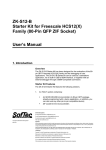
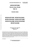
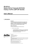
NMIN-12A256B
Single Board Computer
User Manual V.1
NMIN-2114
Aug 18, 2003
Table of Contents
1.0 Overview . . . . . . . . . . . . . . . . . . . . . . . . . . . . . . . . . . . . . . . . . . .
1.1 Noted microcontroller features: . . . . . . . . . . . . . . . . . . . . . . . .
1.2 Included Files . . . . . . . . . . . . . . . . . . . . . . . . . . . . . . . . . . . . .
2
2
3
2.0 Getting Started . . . . . . . . . . . . . . . . . . . . . . . . . . . . . . . . . . . . . .
3
3.0 Memory Map . . . . . . . . . . . . . . . . . . . . . . . . . . . . . . . . . . . . . . . .
5
4.0 Programming the Board. . . . . . . . . . . . . . . . . . . . . . . . . . . . . . .
4.1 BDM Connector and Parallel Port . . . . . . . . . . . . . . . . . . . . . .
4.2 S-Records and the Serial Loader . . . . . . . . . . . . . . . . . . . . . .
4.2.1 Downloading S-Records . . . . . . . . . . . . . . . . . . . . . . . . . . . . .
4.3 On-board Development System . . . . . . . . . . . . . . . . . . . . . . .
4.3.1 Hooking Into Autoboot . . . . . . . . . . . . . . . . . . . . . . . . . . . . . .
4.3.2 Tags . . . . . . . . . . . . . . . . . . . . . . . . . . . . . . . . . . . . . . . . . .
4.3.3 Quick Entry . . . . . . . . . . . . . . . . . . . . . . . . . . . . . . . . . . . . .
4.3.4 Boot Entry . . . . . . . . . . . . . . . . . . . . . . . . . . . . . . . . . . . . . .
4.3.5 Auto Vector . . . . . . . . . . . . . . . . . . . . . . . . . . . . . . . . . . . . .
5
6
6
7
7
7
8
8
8
8
5.0 I/O Connections and Jumpers . . . . . . . . . . . . . . . . . . . . . . . . . .
8
6.0 Board Layout. . . . . . . . . . . . . . . . . . . . . . . . . . . . . . . . . . . . . . . .
10
7.0 Schematic . . . . . . . . . . . . . . . . . . . . . . . . . . . . . . . . . . . . . . . . . .
11
8.0 Examples . . . . . . . . . . . . . . . . . . . . . . . . . . . . . . . . . . . . . . . . . . .
8.1 Playing with the LEDs . . . . . . . . . . . . . . . . . . . . . . . . . . . . . . .
8.2 Reading from the A/D port . . . . . . . . . . . . . . . . . . . . . . . . . . .
8.3 Adding a Sensor . . . . . . . . . . . . . . . . . . . . . . . . . . . . . . . . . . .
8.4 Implementing an Interrupt . . . . . . . . . . . . . . . . . . . . . . . . . . . .
8.4.1 Real Time Interrupt Example . . . . . . . . . . . . . . . . . . . . . . . . . .
8.4.2 Interrupts Calling Forth . . . . . . . . . . . . . . . . . . . . . . . . . . . . . .
8.5 Flash Programming . . . . . . . . . . . . . . . . . . . . . . . . . . . . . . . . .
12
12
12
13
14
15
17
17
User Manual V.1
Aug 18, 2003
1
1.0 Overview
The NMIN-12A256B single board computer provides you with plug and play access to a powerful
microcontroller. The computer board provides power regulation, RS232 and RS422 serial support and an
LCD connector. The microcontroller includes the following built in capabilities:
I/O
ports
BDM
A/D
timers
PWM
Flash
MC9S12A256
Microcontroller
EEPROM
RAM
SPI
interrupts
SCI
I2C
Figure 1 Peripheral interfaces on the MC9S12A256 microcontroller.
1.1 Noted microcontroller features:
•
•
•
•
•
•
•
•
•
•
•
•
•
•
•
•
•
•
•
•
•
•
16-bit HCS12 CPU
Multiplexed External Bus Interface for memory expansion
Interrupt control for all onboard peripherals including priority manipulations
Breakpoints for stepping through code without needing an emulator
Single-wire BDM (Background Debug Mode) for downloading and debugging
low current oscillator, PLL, COP watchdog, real time interrupt, clock monitor
8-bit and 4-bit ports with interrupt functionality
Programmable rising or falling edge triggers
256K Flash EEPROM
4K byte EEPROM
12K byte RAM
8-channel 10-bit 5V Analog-to-Digital Converters
16-bit counter/timer with 8 programmable input capture or output compare channels
Two 8-bit or one 16-bit pulse accumulators
8 PWM channels
Two asynchronous Serial Communications Interfaces (SCI) up to 115K baud
Three Synchronous Serial Peripheral Interface (SPI)
Inter-IC Bus (IIC) compatible with I2C Bus standard
I/O lines with 5V input and drive capability
Operation at up to 50MHz for core and up to 25MHz bus speed for peripherals
Single-Chip and Expanded Modes
Low power modes
User Manual V.1
Aug 18, 2003
2
The computer board’s power consumption is about 60 mA.
1.2 Included Files
The following files are included and are available from our website. The MaxForth files are only available
if you have licensed them:
•
•
•
•
•
•
•
•
•
•
•
•
•
•
as12 - Mac OS X version of the Motorola freeware assembler
as12.exe - PC version of the Motorola freeware assembler
as12.htm - documentation for the assembler
BootEVB-16.S19 - Serial Boot loader, srecord file
DB12DP256-16.S19 - Dbug12 monitor, srecord file
HCS12Manuals.zip - contains a copy of the Motorola manuals for the microcontroller from their
website. Note: these are too big to put on a Floppy so they are available at:
http://www.ee.ualberta.ca/~rchapman/MFwebsite/HCS12/HCS12Manuals.zip
NMIN-12A256Bv1.pdf - this manual in PDF format
Out.S19 - output of converted srecord
rtiled.lst - output of assembled source code
rtiled.s - source code example of an interrupt and power saving instruction WAI
rtiled.s19 - srecord output from assembler
SRecCvt (OSX) - srecord conversion utility for Mac OS X
SRecCvt.exe - srecord conversion utility for PCs
SRecCvtRG.pdf - srecord conversion utility documentation
Licensed files:
• fuzzytest.f - an example file for testing the fuzzy logic support
• mf51fhcs12.map - contains a map of all the bits and pieces in MaxForth for the current release but
may change in future releases. Use with caution.
• MF51FHCS12.S19 - a copy of the MaxForth kernel in Motorola S-record form that can be
downloaded when experimenting with flash
• SCRUB.F - a utility for clearing vectors from EEPROM and flash
• SHT11.F - an example of interfacing to a temperature and humidity sensor
• TESTA24.F - an example to test ATO4
NOTE: Throughout the manual, 0x is used to precede hex addresses in the text for clarity but it
is not used in the MaxForth examples because the numeric base is changed by typing HEX or
DECIMAL.
2.0 Getting Started
Computer
Board
MMC211421142114 (Sika) Flash Programmer
:
Power
Serial Cable
Figure 2 Computer hooked up to board with a serial cable.
You will interact with your board by connecting it to a PC using a serial cable and running a terminal program
such as HyperTerminal or an equivalent setup. You need to set it to 9600 BAUD, one stop bit, no parity and 8
User Manual V.1
Aug 18, 2003
3
data bits. Connect an RS232 serial cable between your PC’s COM port and the serial port on the board. To
power up the board, you need a 7 to 12 volt plug-in transformer plugged into the power jack, PJ1 (AC, DC
both polarities accepted).
Alternatively, you could use Linux or a Mac. On the Mac, ZTerm is a powerful terminal program available as
shareware from the Internet.
When everything is ready and you plug in the power, you should receive a prompt in the terminal program. If
you have the J4 jumpers set to the serial loader position:
D-Bug12 Bootloader v1.0.0
a) Erase Flash
b) Program Flash
c) Set Baud Rate
d) Erase EEPROM
?
or if the J4 jumpers are set to the application position and the D-Bug12 monitor application is loaded:
D-Bug12 4.0.0b18
Copyright 1996 - 2002 Motorola Semiconductor
For Commands type "Help"
>
or if the J4 jumpers are set to the application position and MaxForth is loaded:
Max-FORTH V5.1F
(license agreement is required)
And when you depress the ENTER key, it should respond with
type ? for help
:
or
>
or
OK
(Max-FORTH prompt)
When you see that message, it means the communication is established and you are ready to interact with
the board and microcontroller. By pressing the reset button, RS1, you should get the same boot prompt as
when you powered it up. Pressing the reset button will leave the contents of most of the RAM intact which
might be useful for debugging purposes, whereas, if you power cycle the board, then all RAM contents will be
lost.
User Manual V.1
Aug 18, 2003
4
3.0 Memory Map
The memory map consists of RAM, ROM and registers. The interrupt vectors exist in protected flash space
along with the serial loader. Since they can’t be changed, a secondary vector table exists at 0xEF80. There
is a one to one correspondence with the primary vector table. Since these locations can only be written once,
the entire 512 bytes must be erased to change a vector. For prototyping, the vector can be set once to point
into EEPROM which can be erased more easily.
When only the serial loader is loaded, it relocates RAM to the top of memory and copies itself to it to run only
out of RAM. This allows the changing of page F through the flash window at 0x8000. The MaxForth system
takes up space in page E and page F of flash leaving pages 0 to page D available for use. None of the
EEPROM is used so it is all available for use for user applications.
Serial Loader
0xFFFF
RAM
MaxForth
0xFFFF
0xD000
Flash
Page F
Flash
Page F
0xC000
primary vectors
0xFF80
serial loader
secondary vectors 0xF000
0xEF80
system
0xC000
Flash
window
pages 0-F
0x8000
Flash
window
pages 0-D
free
space
0x8000
system
Flash
page E
0x4000
Flash
page E
0x4000
RAM
0x1000
0x1000
EEPROM
0x0400
0x0000
registers
EEPROM
0x0400
0x0000
free
space
system
free
space
registers
Figure 3 After booting, the RAM memory map either belongs to the serial loader or
the MaxForth application.
4.0 Programming the Board
When the board is reset, it executes the program pointed to by the vector at location 0xFFFE. In a loaded
board this will be the boot loader which will either start the serial loader or MaxForth. When MaxForth starts,
it checks to see if there is an autostart application present and runs it or else it just runs MaxForth.
There are several ways in which to program the board:
1.
User Manual V.1
download an s-record through the BDM connector and the PC parallel port using a programmer
Aug 18, 2003
5
2.
3.
such as P&E Micro’s BDM programmer.
download s-records using the embedded serial loader and a serial port with HyperTerminal,
NMITerm or equivalent
interact directly with the microcontroller and download source code to the on-board
development system, MaxForth, through a serial port and HyperTerminal
When downloading text files to the board, using the text download protocol, make sure the delay per line is at
least 100 milliseconds. You can risk having lines missed if you go to fast, but with some setups, it is possible
to use smaller line delays which has a nice effect on a long download. Your mileage will vary.
4.1 BDM Connector and Parallel Port
Using the HCS12 cable from P&E Micro or equivalent, plug it into the parallel port of your computer
through a parallel port cable and the BDM port on the computer board making sure to orientate the
triangle on the pin header to pin 1 on the board which is marked by a square solder pad on the bottom of
the board. Apply power to the board. When disconnecting from the board make sure it goes through a
power cycle before you try out the downloaded software since a reset is not enough to regain control of
the microcontroller after interacting with the BDM port.
Check the help screens for more details.
4.2 S-Records and the Serial Loader
Using the serial loader, you can download s-records that have been created by a C compiler or
Assembler program that you have acquired separately, to flash memory to be run. The help menu,
invoked by typing a ?, is:
? ?
a) Erase Flash
b) Program Flash
c) Set Baud Rate
d) Erase EEPROM
?
The serial loader works by running out of RAM. At bootup, the boot program in flash checks to see if
there is an application by checking for a vector at 0xEFFE. If there isn’t, then it copies the serial loader
program from flash to RAM and then runs the program. The serial loader program must run out of RAM
to be able to program flash memory.
If you download an application, reboot and nothing happens, you can recover to the serial loader by
setting the jumpers on the J4 connector with a jumper or equivalent and pressing the reset button. You
will be taken back to the serial loader where you can erase your errant application and try again.
Figure 4 Jumper positions on the J4 connector for booting into the serial loader or
an application. If there are no jumpers, then the default will be the Application. This
is important if you intend to use channel 0 and 1 of the A/D input since leaving
jumpers in the Application position will prevent those inputs from being used.
User Manual V.1
Aug 18, 2003
6
4.2.1 Downloading S-Records
The serial loader uses a simple text transfer protocol to transfer data from the host computer to the
board. Depending on your host program and its defaults, the setting may be not right. Try it first and if it
doesn’t work, modify some of the settings.
To install a fresh copy of MaxForth and erase all the flash, do the following:
1.
get to the serial loader from Forth by FLASH or by resetting with the J4 connector set like in
Figure 4.
2. press a
3. wait till done, then press b
4. download the MaxForth s-record with the text protocol, by cutting and pasting or dragging and
dropping if supported
5. wait till done, then press reset with the J4 jumpers removed or in the Application position
Quick Tip !! For an extremely fast download, you could try setting the baud rate to 115200, set
line delay to zero and flow control to X-ON/X-OFF. Using this setup, you can download the
entire kernel in seconds when needed. You could also use this method to download s-records
to flash for code to be autostarted or run from MaxForth.
4.3 On-board Development System
Taking advantage of the interactive nature of the board’s development system, MaxForth, you can
interact directly with the microcontroller’s peripherals by fetching and storing values to the memory
mapped configuration registers for the peripheral devices. This is an effective way of understanding the
peripheral documentation, verifying correct initialization sequences, running some tests on different
configurations and debugging driver code as you develop it. By typing in new definitions, you can add
new macros to the dictionary for interactive use or for creating an automated program. Some examples
are given later on.
4.3.1 Hooking Into Autoboot
You can autoboot an application by leaving a vector to it at location 0xEFFE. The startup boot loader will
detect this vector and then jump to the location that the vector is pointing to. When MaxForth is installed,
it has a vector at that location. To get to the serial loader from MaxForth, type in FLASH and hit enter. To
get back to the serial loader from an application, jump to location 0xF02E in memory. The application
area can be erased using the serial loader without the boot loader being removed from memory.
MaxForth occupies the space from 0x4000-0x7FFF and 0xC000-0xC911. At location 0xEFFE is the
start vector for MaxForth which is what the bootloader looks for when booting. MaxForth can be
replaced by erasing it and writing a new application in its place, making sure that the startup vector for
the new application is at 0xEFFE.
If you want to hook into the MaxForth autoboot system, then there are several places where you can do
this:
• quick entry - allow setting of COP and other write-once registers on the micro.
• boot entry - MaxForth has been setup and can be augmented
• auto vector - last possible chance before Forth is started up
User Manual V.1
Aug 18, 2003
7
Table 1: Noted Memory Locations for Startup Hooks
Name
Value
Notes
quick_tag
0x0FEC
store a tag1
quick_vector
0x0FE8
CFA of word to call
boot_tag
0x0FE0
store a tag2
boot_vector
0x0FE4
CFA of word to call
boot_start
0x0400
lower limit in flash for checking for an auto vector tag2 on a
1K boundary
boot_end
0xF000
upper limit of flash for auto
vector tag2 checking
1. A55A
2. A44A for first autostart or A55A for continuous last autostart.
4.3.2 Tags
The patterns 0xA44A and 0xA55A are referred to as tags and are used during the autoboot process to
find vectors to be executed during the bootup process. Only the lowest A44A and A55A tag will be
executed with A44A going first. This applies to the boot entry and autovectors. The quick entry, if used,
only uses A55A.
4.3.3 Quick Entry
Quick entry lets you get in on the boot process and set COP or any other write once registers before
MaxForth starts up. The tag contains a bit value that is checked first and if present, then the CFA stored
at the vector preceding it is executed.
HEX A55A FEC EE!
' COP-RUN CFA FE8 EE!
( hook into quick entry vector )
4.3.4 Boot Entry
Boot entry lets you take over or execute something after MaxForth has been initialized. This is a good
time to modify the dictionary linkage to add extra words from flash. The vector follows the tag.
HEX A44A FE0 EE!
' STARTUP CFA FE4 EE!
( hook into boot-start vector )
4.3.5 Auto Vector
As well, at any 1K boundary in RAM, EEPROM or flash you can lay down a tag followed by a vector.
HEX 1000 AUTOSTART STARTUP ( hook into auto-start vector )
5.0 I/O Connections and Jumpers
The jumpers and I/O headers from the board are as follows:
•
•
•
•
•
•
•
J1 is the primary serial port, SC0, that is used for the serial bootloader, dbug12 monitor and MaxForth
J2 is the second serial port, SCI1.
J3 is the jumper for LCD contrast.
J4 is for selecting boot to Serial Loader or application such as MaxForth
J5 is the analog input header
J6 is the I/O and other peripheral interface signals
J7 is the jumpers for future memory expansion
User Manual V.1
Aug 18, 2003
8
•
•
•
•
J8 is the LCD connector, or SPI, or Timers shared I/Os
J9 is the BDM OUT that supports motorola DBUG12 POD mode.
J10 is the BDM in interface.
DB2 has the same pinout as J6 for Dsub 44 pin. The connector is not installed.
Additionally:
•
•
•
•
the red LED is controlled by port M bit0, PM0
the green LED is controlled by port M bit1, PM1
Resistor POT, R4 provides the voltage to the LCD that is used to adjust the LCD contrast
RS1, reset switch
User Manual V.1
Aug 18, 2003
9
6.0 Board Layout
PJ1
DB1
(0,3.225)
J1
(2.400,3.225)
(2.250, 3.000)
1
C1
CACB
(2.300,2.825)
(0.100,2.225)
C3
R7
C4
R13
R9
C10
R5
C18
HC05
VR1
LM2937
C9
C12 C11
U2
XTAL1
Y1
LD2 R6
U3
CR1
C6
C8
C13
C14
C15
LD1
R12
(0.100,1.800)
J3
MAX232N
C2
R8
RP1
C7
J9
J8
J2
9
C5
J10
6
D1
(0.100,2.600)
BKGD
(0.150,2.800)
R10
R11
RS1
C16
(2.300,1.625)
R4
J4
C17
R2 R3
J5
R1
C19
(0.150,0.900)
L2
J7
L1
(2.250,0.900)
U1
BCN01
J6
(2.300, 0.600)
DB2
WWW.NEWMICROS.COM
(0.275,0.225)
(2125,0.225)
(2400,0)
(0,0)
User Manual V.1
Aug 18, 2003
10
D
C
B
A
CA
8
J1
1 1
2
3
4
5
5
6
9
SCI0
J2
6
7
8
9
3
8
6
4
2
5
10
1
7
J10
9
SCI1
1
BDM IN
J9
BDM OUT
C2
1uF
12
+5V
HC05
13
47K
+5V
R11
1
0.1uF
4.7K
R10
BKGD
10K
+5V
R9
PT7
0.1uF
CB
8
VRH
7
2
4
6
U2
1
C3
5
PAD03
PAD01
R8
C4
1uF
RESET
10K
+5V
1uF
3
RxD0
C1
10
9
1uF
8
7
RxD1
TxD1
TxD0
SI0
SO0
12
11
4
PAD05
VRL
13
14
6
PAD07
10K
PAD01
LVI1
1
3 S80840
RS1
R6
SI1
SO1
3
8
2
MAX232CWE
J5
PAD00
5
10
1
PAD02
7
2
R4
+5V
9
A/D
+5V
J4
PAD04
10
PAD06
10K
+5V
R5
PT6
1N4148
D1
PAD00
+5V
R1
10K
HC05
11
7
6
C18
PJ1
2.2K
6
R4
+5V
J3
10K
J7
VRH
0.1
VRL
C17
0.1
L2
10uH
R2
R3
CR1
10K
10K
VM08
+5V
R7
4.7K
L1
C11
Y1
22PF
16Mhz
5
22PF
C13
.047
C10
10uH
.0047
C12
71
72
73
63
64
65
66
46
76
75
71
70
16
15
14
15
30
25
26
32
31
77
29
59
60
61
62
49
9
36
28
33
10
50
76
34
35
PM4
PM3
PM2
PS0/RXD0
PS1/TXD0
PS2/RXD1
PS3/TXD1
PAD00
PAD01
PAD02
PAD03
PAD04
PAD05
PAD06
PAD07
BKGD
RESET
PE6
PE5
XFC
GND
PT0
PT1
PT2
PT3
PT4
PT5
PT6
PT7
VREGEN
PM1
PM0
PJ6
PJ7
PA0
PA1
PA2
PA3
PA4
PA5
PA6
PA7
PB0
PB1
PB2
PB3
PB4
PB5
PB6
PB7
PE0
PE1
PE2
PE3
PE4
PE7
PM5
PP0
PP1
PP2
PP3
PP4
PP5
PP7
C9
U1
VDDPLL
VDDX
VDDR
VDDA
VRH
VRL
VSSA
VDD2
VDD1
TEST
VSSR
VSSPLL
VSS1
VSS2
VSSX
EXTAL
XTAL
C6
0.1uF
OUT
VR1
LM2937
C7
0.1uF
IN
100uF
5
MC9S12A256B
5
6
7
8
11
12
13
14
67
74
75
69
68
41
42
43
44
45
46
47
48
16
17
18
19
20
21
22
23
40
39
38
37
27
24
70
4
3
2
1
80
79
78
+5V
+5V
C8
4
100uF
4
+5V
C19
VSS
J8
3
+5V
PT1/D1
PM2/RS/MISO0
PT3/D3
Vo
PT5/D5
PM4/E1/MOSI0
PT0/D0
PM3/RW/SS0
PT4/D4
PT2/D2
DB2
SHARED IO/LCD/SPI
1
2
3
4
5
6
7
8
9
10
11
12
13
14
15
VDDPLL
C14
VSSPLL
C5
+5V
PM5/E2/SCK0
PT7/D7
NC
PT6/D6
PJ7
PJ6
PS3
PS2
PS1
PS0
PA7
PA6
PA5
PA4
PA3
PA2
PA1
PA0
VSS
C15
+5V
BYPASS CAPACITORS
VDDA
C16
VSSA
3
31
17
32
18
33
19
34
20
35
21
36
22
37
23
38
24
39
25
40
26
41
27
42
28
43
29
44
30
16
PB7
PE6
PB6
PE5
PB5
PE4
PB4
PE3
PB3
PE2
PB2
PE1
PB1
PE0
PB0
PP7
PM5
PP5
PM4
PP4
PM3
PP3
PM2
PP2
PM1
PP1
PM0
PP0
PE7
PM0
3
1
APPROVALS
T.V.N
C.N.
2
2
4
2
HC05
5
HC05
PM1
DRAWN
CHECKED
FINISH
PP0
PP2
PP4
GND
PA0
PA2
PA4
PA6
PS0
PS2
PM0
PM2
PM4
PJ6
PE0
PE2
PE4
PE6
PB0
PB2
PB4
PB6
+5V
6
DATE
051303
052103
J6
TITLE
LD2
LD1
46
44
42
40
38
36
34
32
30
28
26
24
22
20
18
16
14
12
10
8
6
4
2
SIZE
D
SCALE
300
R12
+5V
R13
PP1
PP3
PP5
PP7
PA1
PA3
PA5
PA7
PS1
PS3
PM1
PM3
PM5
PJ7
PE1
PE3
PE5
PE7
PB1
PB3
PB5
PB7
8
300
45
43
41
39
37
35
33
31
29
27
25
23
21
19
17
15
13
11
9
7
5
3
1
HC05
9
NMIN-12A256B
DRWG #
BCN01
1
SHEET
1
REV
02
D
C
B
A
8.0 Examples
These examples may be typed in interactively or cut and pasted into the terminal window if you are using
MaxForth. Alternatively, they can be translated to the language that you are using to program the
microcontroller with.
8.1 Playing with the LEDs
There is a green and red LED attached to port M bits 1 and 0 respectively. You can easily turn these on
and off from MaxForth using the following code. Note that constants are defined for the registers for
convenience:
HEX
250 CONSTANT PTM
252 CONSTANT DDRM
1 DDRM C!
1 PTM C!
2 DDRM C!
2 PTM C!
3 DDRM C!
3 PTM C!
(
(
(
(
(
(
(
(
define port M address
define data direction register for port m
set bit 0 as an output and all others as inputs
turn on the red led connected to bit 0
set bit 1 as an output and all others as inputs
turn on the green led connected to bit 1
set bits 0 and 1 as outputs; all others as inputs
turn on both leds
8.2 Reading from the A/D port
For this example we will consider the simplest way to get an A/D reading:
get A/D
reading
initialize
A/D
request
channel 0
channel
0?
not yet
display
reading
Done.
This involves: setting up the A/D registers so it is ready to go; requesting a read of a channel; waiting for
that channel to complete converting; and finally, reading and displaying the value. Each of these boxes
on the diagram will become a word except for Done.
HEX
( A/D peripheral registers
82 CONSTANT ATD0CTL2
83 CONSTANT ATD0CTL3
User Manual V.1
Aug 18, 2003
12
84
85
86
90
CONSTANT
CONSTANT
CONSTANT
CONSTANT
ATD0CTL4
ATD0CTL5
ATD0STAT
ATD0DR0
: INIT-A/D ( -- )
7 ATD0CTL4 C!
( 10 bit resolution; prescaler greater than 6
40 ATD0CTL3 C! ( 8 conversions per sequence
C0 ATD0CTL2 C! ; ( power up, fast flag clear and interrupts off
: REQUEST0 ( -- )
80 ATD0CTL5 C! ; ( 8 conversions, right unsigned, one-shot, channel 0
: CHANNEL0?
( -- f )
ATD0STAT C@ 80 AND ;
: DISPLAY-READING
( -- )
: GETAD
REQUEST0
INIT-A/D
ATD0DR0 @ . ;
BEGIN
CHANNEL0?
UNTIL
DISPLAY-READING ;
8.3 Adding a Sensor
The SHT11 from Sensirion is a smart sensor combining temperature and relative humidity sensors with
an onboard conversion and a two wire communication facility all in a very tiny package. In the following
example it is hooked up to PORT T of the microprocessor. One line is used to provide clock and the
other line is used as a bidirectional line for communication.
( SHT11 interface for MaxForth
(
(
(
(
(
(
Rob Chapman
Aug 13, 03
The SHT11 sensor chip provides 14 bit resolution on temperature and
12 bit resolution on relative humidity. The four pins connect to
+5, GND, PT1 for clock and PT3 for data.
PT1 is the serial clock; PT3 is the data line and is bidirectional so
care must be taken not to drive it high, just low so there will be no
conflicts. It can be driven low but is pulled high by pull up resistor.
HEX
( Registers
242 CONSTANT DDRT
240 CONSTANT PTT
244 CONSTANT PERT
( data direction register for port T
( port t outputs
( port t enable for pull ups
( Debugging
: PT7TRIG ( pulse pt7 low for debugging with scope
DDRT C@ 80 OR DUP DDRT C! ( enable PT5 output
PTT C@ AND 7F AND DUP PTT C! ( set it low
80 OR PTT C! ; ( set it high
(
:
:
:
:
:
Clocks
K1 2 PTT C@ OR PTT C! ;
K0 2 NOT PTT C@ AND PTT C! ;
K01 K0 K1 ;
K10 K1 K0 ;
K10S 0 DO K10 LOOP ;
( Data
User Manual V.1
Aug 18, 2003
13
: D0 A DDRT C! PTT C@ 8 NOT AND PTT C! ;
: D1 2 DDRT C! ;
( Protocol: 8 bit command and 16 bit data
: SHT-CMD ( n -- ) D1 K0 9 K10S K1 D0 K01 D1 K0 D0 3 K10S
10 5 0 DO K0 2DUP AND IF D1 ELSE D0 THEN K1 2/ LOOP 2DROP
D1 K01 K0 ;
: DAT-READY? ( -- f ) PTT C@ 8 AND 0= ;
: GET-8 ( n -- n' ) 8 0 DO K0 2* PTT C@ 8 AND IF 1 OR THEN K1 LOOP ;
: GET-DAT ( -- n ) 0 GET-8 K0 D0 K10 D1 GET-8
K01 K0 ;
( Exchanges
: RST 1E SHT-CMD ;
( Initial setup
: INIT-SHT
2 PLACES
( for printout format
2 DDRT C!
( clock is output always
FF PERT C! ; ( pull up enabled
DECIMAL
( Tests for temperature in Celsius and relative humidity (RH)
( Values obtained from chip are in a raw format and need to be massaged
(
Formula for temperature: -40 + .01*rawTE
(
Formula for linear RH: -4 + rawRH*(.0405 + -2.8*10-6 * rawRH )
(
Formula for true RH: linRH + (TE-25)( .01 + .00008*rawRH)
: TEMP 3 SHT-CMD BEGIN DAT-READY? UNTIL
S>F .01E F* 40E F- F. ;
GET-DAT
: RELH 5 SHT-CMD BEGIN DAT-READY? UNTIL GET-DAT
S>F FDUP -2.8E-6 F* .0405E F+ FOVER F* 4E F- ( linear RH
FSWAP ( linear rh \ raw rh
3 SHT-CMD BEGIN DAT-READY? UNTIL GET-DAT
S>F .01E F* 40E F- ( temperature for compensation
( linear rh \ raw rh \ temp
25E F- FSWAP .00008E F* .01E F+ F* F+ ( RH true ) F. ;
To get results from the sensor chip you must first initialize the port and then get data. For example if we
get data and then breath on the chip to increase humidity and humidity we can get the following results:
INIT-SHT OK
TEMP 26.36C
RELH 43.94%
( breathe on
TEMP 27.75C
RELH 80.76%
OK
OK
sensors for 5 seconds
OK
OK
8.4 Implementing an Interrupt
The HCS12 contains a lot of parts to get right (usually all of them) before you can make an interrupt
(more generally referred to as an exception) happen. You must set up the CPU, the interrupt controller
and an interrupt source such as a peripheral. Setting up the CPU involves modifying CPU control
register while setting up the interrupt controller and peripheral involves modifying their memory mapped
control registers.
User Manual V.1
Aug 18, 2003
14
The interrupt machinery on the HCS12 supports a wide range of operational capabilities. You can just
use one interrupt or support a complex system of prioritized interrupts from all peripherals. Interrupts
can even be forced to happen to provide for a way of testing or syncing.
To set up an interrupt you'd f ollow these steps:
1.
2.
3.
4.
write an interrupt service routine which will turn off the source of the interrupt when invoked by
the interrupt. This routine must end with the assembly instruction rti.
put the address of this routine in the right location in the secondary vector table
enable the peripheral
enable interrupts
8.4.1 Real Time Interrupt Example
The real time interrupt is a simple interrupt to enable and service so it is a good one to start with. This
following example is written in assembler and be compiled on a computer and downloaded with the serial
loader:
;
;
;
;
RTI interrupt vector Rob Chapman Jun 20, 2003
startup sets up port M and initializes the real time interrupt (RTI), turns
on the green LED and then does nothing
the RTI just changes the red LED every 64ms
; Registers Used
CRGFLG equ $37
RTICTL equ $3B
CRGINT equ $38
DDRM
equ $252
PTM
equ $250
; Startup code
org $C000
startup:
lds #$4000
movb #$03,DDRM
movb #$02,PTM
movb #$7F,RTICTL
movb #$80,CRGINT
cli
lowpower:
wai
bra lowpower
; Service interrupt routine
sir_rti:
movb #$80,CRGFLG
ldaa PTM
eora #01
staa PTM
rti
;
;
;
;
;
RTI interrupt flag
RTI control register
RTI interrupt control
port M data direction register
port M outputs: 0 is red, 1 is green
;
;
;
;
;
;
establish a stack
drive port M bits 0 and 1
turn off red LED and turn on green LED
64ms timer
enable RTI interrupts
enable interrupts
; go to low power mode
; save energy
for real time interrupt
; reset RTI interrupt
; toggle red LED
; return from interrupt
; secondary vector table additions
; rti tie in
org $EFF0
; RTI vector
dw sir_rti
; startup tie in
User Manual V.1
Aug 18, 2003
15
org $EFFE
dw startup
; application vector
To compile this program, you can use the freeware assembler as12 on a PC or a Mac. The assemblers
are with the included files. Once the program is compiled, you must then convert the output srecord with
another freeware program sreccvt. This gets it into the right download format. Then you download the
file and once it is done, press the reset button. You should see the green LED light and the red LED flash
rapidly.
NOTE: If you are using the D-Bug12 monitor application, then you will not have to convert the
s-record format but you should org to a different address.
On a PC you can assemble and convert from a DOS command prompt and then download with a
terminal program. You can either put the as12 and sreccvt programs right in your working directory or
put them elsewhere and then add the path to your autoexec.bat file. Once you’ve established the proper
sequence, you can automate it by putting it into a batch file.
On a Mac using OS X, you assemble and convert using a unix terminal window. You can either keep the
programs local or put them into a common directory. For instance you could do the following:
sudo cp as12 /usr/bin/
Password:
rehash
This puts the as12 program into your /usr/bin directory so that you can call it from anywhere. The
same procedure can be done for sreccvt. The rehash command just makes the new command
available right away.
To assemble the program:
as12 rtiled.s > rtiled.lst
This will produce two outputs. The .lst file is a listing of the assembled program while the .s19 file is the
output srecord. The srecord file must then be converted to the correct format for downloading:
sreccvt -m 00000 fffff 32 -lp rtiled.s19
SRecCvt v1.0.11
Converting S-Record File: rtiled.s19
S-Record File Conversion Complete
If you want to see the output, you can view it from the command line:
more Out.S19
S2240FC000CF4000180B030252180B020250180B7F003B180B80003810EF3E20FD180B800057
S2240FC02037B6025088017A02500BFFFFFFFFFFFFFFFFFFFFFFFFFFFFFFFFFFFFFFFFFFFF63
S2240FEFE0FFFFFFFFFFFFFFFFFFFFFFFFFFFFFFFFC01CFFFFFFFFFFFFFFFFFFFFFFFFC0007D
S9030000FC
Download the program by first selecting a to erase the flash and then b followed by the above srecord:
D-Bug12 Bootloader v1.0.0
a)
b)
c)
d)
Erase Flash
Program Flash
Set Baud Rate
Erase EEPROM
User Manual V.1
Aug 18, 2003
16
? a
a) Erase Flash
b) Program Flash
c) Set Baud Rate
d) Erase EEPROM
? b
***
Reset the board.
If all goes well, the green LED should be on and the red LED should be blinking. Make sure you change
the J4 jumpers for the application to run.
8.4.2 Interrupts Calling Forth
As for calling a Forth word from an interrupt, this is doomed to fail at some point since not all Forth words
including the virtual machine are interruptible without some extra context savings. This all adds overhead
and goes against keeping interrupts as short as possible. If you keep your interrupts simple and in
assembler, then they have a greater chance of working and meeting system time constraints.
8.5 Flash Programming
There is 256K of flash memory available on chip but since the microcontroller has only 16 bits of address
space, or 64K, you must access the flash through a programming window.
Flash memory may only be written when it is in the region 0x8000-0xBFFF which is referred to as the
program memory page window. This region is a 16K window which can be used to access all of the
256K of flash memory. To change which 16K region of memory is accessed there, you need only change
the PPAGE (0x30) register. Since there is only 256K of flash but the register is 8 bits, the memory
windows will be unique for a small range only and then wrap after that. For example, putting 0 into
PPAGE (HEX 0 30 C!) will access the lowest 16K of the 256K flash memory, but so will 16, 32, 48, etc. To
access the top page of flash, which also appears in the memory map from 0xC000 to 0xFFFF, you would
store 15, 31, 47, etc. into the PPAGE register (HEX F 30 C!). These sections of flash are referred to as
pages of flash. As noted in the memory map (Figure 3 on page 5), page E and page F are permanently
in the CPU memory map but they can also be accessed through the programming page window. For
instance if you store 14 into the PPAGE register, you will see the same memory image at location 0x4000
as you will see at 0x8000. If you want to install interrupt vectors in the secondary vector table at 0xEF800xEFFF, then you must put page F into the programming window. For instance if you want to install an
interrupt vector for the real time interrupt (RTI) which is at 0xEFF0, you'd do the f ollowing:
HEX
F 30 C!
address_of_interrupt_vector AFF0 FL!
Note that 0xAFF0 is 0x4000 less than where the actual interrupt vector is to be but that it will appear
there. If you try to use FL! in any other memory area outside of the programming window, it will not work.
As described in the microcontroller manual on flash memory, the upper 16 bytes of EEPROM are
reserved as control registers for the EEPROM. You should avoid setting values in this range (0xFF00xFFF) unless you know what you are doing. Setting the wrong values in this region has the potential to
lock out use of the EEPROM from being erased.
The EEPROM differs from the flash memory in two other aspects. Its erase size is 4 bytes while the flash
is 512 bytes. This makes the EEPROM easier to reprogram in small amounts. In MaxForth you can
program a byte location irregardless of its value as it will be erased first by EEC! if necessary. In flash
memory, the minimum programming size is an aligned 2 bytes and the location must be 0xFFFF to begin
with. To program EEPROM use EEC!, EE!, EEMOVE and EEWORD. To program flash, use FL!,
FLMOVE, FLERASE and FLWORD. EDP is used by EEWORD and FDP is used by FLWORD.
User Manual V.1
Aug 18, 2003
17