1
Contents
326X Series Modem Reference Guide
Chapter 1. AT Commands
AT, AT& and AT Command Descriptions .................................................
Selecting Options and Settings .................................................................
ATD (Dialing an Unstored Telephone Number) ...........................................
ATDS, AT DS (Dialing a Stored Telephone Number) ...............................
ATE (Asynchronous Echo) ...........................................................................
ATH (Busy Out Test) ....................................................................................
ATL (Speaker Volume) .................................................................................
ATM (Speaker Control) .................................................................................
ATO1 (Retrain) .............................................................................................
ATP, ATT, AT PT (Dial Type) .....................................................................
ATQ (Result Codes) ......................................................................................
ATS (S-Register)............................................................................................
ATT (Dial Type) ............................................................................................
ATV (Result Code Format) ...........................................................................
ATX (Call Progress) .....................................................................................
ATY (Longspace Disconnect) ......................................................................
ATZ (Selecting an Option Set) ......................................................................
AT& Commands ...........................................................................................
AT&C (DCD Control) ...................................................................................
AT&D (DTR Control) ..................................................................................
AT&F (Reinitialize Memory) ........................................................................
AT&G (Guard Tone) .....................................................................................
AT&I (Display Modem ID) ..........................................................................
AT&J (Dial Line Jack Types) ........................................................................
AT&L (Line Type) ........................................................................................
AT&M (AT Data Format) .............................................................................
AT&P (Pulse Cycle) ......................................................................................
AT&R, AT CT (CTS Control) ....................................................................
AT&S, AT MR (DSR Control) ...................................................................
AT&T (Test) ..................................................................................................
AT&T4, AT&T5 (Accept RDL) ....................................................................
AT&V, AT ST (Modem Status Display)......................................................
Operating Status Messages .......................................................................
DTE Rate/Status Summary ......................................................................
Error-Correction and Data-Compression Status........................................
Transmit and Receive Throughput and Link Utilization Status Display ..
EIA/TIA 232-D (CCITT V.24) Signal Status ...............................................
Status Summary Line ...............................................................................
Display Modem ID ...................................................................................
CQMS Parameter Status ...........................................................................
AT&W (Save Changes: Creating New Option Sets) .....................................
AT&X (Clock) ..............................................................................................
AT&Y (Power Up in Option Set) .................................................................
*
*
*
*
*
*
1-5
1-8
1-10
1-10
1-11
1-11
1-11
1-12
1-12
1-13
1-13
1-14
1-14
1-14
1-15
1-18
1-18
1-19
1-19
1-20
1-22
1-22
1-23
1-24
1-25
1-26
1-27
1-28
1-29
1-30
1-31
1-31
1-32
1-34
1-35
1-36
1-37
1-38
1-41
1-41
1-45
1-47
1-47
v
Contents (continued)
Chapter 1. AT Commands (Continued)
AT&Z, AT CN (Enter Telephone Numbers) ...............................................
AT Commands ...........................................................................................
AT AA (Answer) ........................................................................................
AT AP (Adaptive Rate) ..............................................................................
AT AS (Answer in Restoral) ......................................................................
AT AY (Auto Type) ....................................................................................
AT BD (Blind Dial) ....................................................................................
AT BK (Break Handling) ...........................................................................
AT CA (Answer/Originate Mode)...............................................................
AT CD (DCD Loss Disconnect)..................................................................
AT CM (Connect Message).........................................................................
AT CN, AT&Z (Entering Telephone Numbers) .........................................
AT CT, AT&R (C, TS) ................................................................................
AT DA (Default Dialing) ............................................................................
AT DB (Buffer Delay) ................................................................................
AT DC (Data Compression) .......................................................................
AT DD (Dial Wait) .....................................................................................
AT DE (DTE Rate)......................................................................................
AT DF (Data Format) .................................................................................
AT DI (Leased to Dial Option) ...................................................................
AT DL (RTS/CTS Delay) ...........................................................................
AT DP (Pause Delay) .................................................................................
AT DR (Auto Redial) .................................................................................
AT DS, ATDS (Dial a Stored Telephone Number) .....................................
AT DT (DTR Delay) ..................................................................................
AT EC (Error Correction) ...........................................................................
AT FC (Fast Call) ........................................................................................
AT FL (Flow Control) ................................................................................
AT HD (Hold Dial Line) ............................................................................
AT LA (DTE Circuit 141) ...........................................................................
AT LC (Line Compensation).......................................................................
AT LD (DTE Circuit 140) ...........................................................................
AT LE (Dial to Leased Option, Automatic Disconnect) ............................
AT LL (Local Analog Loopback Test Busy Out) .......................................
AT LN (Link Telephone Numbers) .............................................................
AT LS (Low Speed) ....................................................................................
AT LT (DTE Pin 25) ...................................................................................
AT MD (PSTN Signaling) ..........................................................................
AT MF (Modem Flow Control) ..................................................................
AT MM (Modulation Mode) ......................................................................
AT MN (Minimum Rate) ...........................................................................
AT MR, AT&S (DSR Control) ...................................................................
AT MS (AT Messages) ...............................................................................
AT MX (Maximum Rate) ...........................................................................
*
*
*
*
*
*
*
*
*
*
*
*
*
*
*
*
*
*
*
*
*
*
*
*
*
*
*
*
*
*
*
*
*
*
*
*
*
*
*
*
*
*
*
vi
*
1-48
1-49
1-49
1-50
1-51
1-52
1-52
1-53
1-53
1-54
1-54
1-54
1-54
1-55
1-56
1-57
1-57
1-58
1-59
1-59
1-60
1-60
1-61
1-61
1-61
1-62
1-63
1-64
1-66
1-68
1-68
1-69
1-69
1-70
1-70
1-71
1-72
1-72
1-74
1-74
1-76
1-76
1-76
1-77
Contents (continued)
Chapter 1. AT Commands (Continued)
AT NB (Buffer Option) ..............................................................................
AT NC (Network Compensation)................................................................
AT ND (View Stored Telephone Numbers) ...............................................
AT OC (External Control) ..........................................................................
AT OP (External Option Set Select) ...........................................................
AT OS (Overspeed) ....................................................................................
AT PE (Enable/Disable Password Protection) ...........................................
AT PF (Set Protection) ...............................................................................
AT PN (Unlock Password Protection).........................................................
AT PT (Dial Type) ......................................................................................
AT PW (Change Password) ........................................................................
AT RA (Remote Access) ............................................................................
AT RC (Initiate, Terminate, or Abort Remote Configuration Session) ......
Initiating a Remote Configuration Session with a Dial Modem ..............
Initiating a Remote Configuration Session with a Leased Line Modem ..
Terminating a Remote Configuration Session ..........................................
Aborting a Remote Configuration Session ...............................................
AT RE (Initiate/Terminate Restoral) ..........................................................
AT RP (Parity) ............................................................................................
AT RS (RTS Control) .................................................................................
AT RT (Auto Retrain) .................................................................................
AT SC (Speed Conversion) ........................................................................
AT SI (DTE Inactivity) ...............................................................................
AT SL (Error Correction ID).......................................................................
AT SM (Data Transfer Mode) ....................................................................
AT SR (RTS/DCD Remote Signaling) .......................................................
AT ST, AT&V (Modem Status Display) ....................................................
AT TD (Throughput Delay Minimization) .................................................
AT TL (Tone Length) .................................................................................
AT TT (Call Timeout) .................................................................................
AT XC (Error Correction Reliable Messages) ...........................................
AT ZC (Callback Feature)...........................................................................
AT ZD (Dial Restricted) .............................................................................
AT ZI (Enter Access Security Group Password) ........................................
AT ZP (Select Tones with Access Security) ...............................................
AT ZR (Remote Number Required) ...........................................................
AT ZS (Simulated Ringback) ......................................................................
AT ZV (Password Verification) ..................................................................
*
*
*
*
*
*
*
*
*
*
*
*
*
*
*
*
*
*
*
*
*
*
*
*
*
*
*
*
*
*
*
*
*
*
1-77
1-78
1-78
1-79
1-79
1-80
1-80
1-80
1-81
1-81
1-82
1-82
1-83
1-83
1-85
1-86
1-86
1-87
1-90
1-91
1-92
1-93
1-93
1-94
1-94
1-96
1-97
1-97
1-98
1-98
1-99
1-100
1-101
1-101
1-102
1-102
1-103
1-103
vii
Contents (continued)
Chapter 2. Front Panel Operation
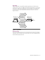
Introduction ..................................................................................................
Status/Option Sets/Dialing Menu .................................................................
Test Options ..................................................................................................
Modulation Options ......................................................................................
Restoral Options ...........................................................................................
Restoral Indications ..................................................................................
Configuring for Dial Restoral ...................................................................
Interpreting the DTR Option Setting.........................................................
Error Correction and Data Compression Options .........................................
ACU Options ................................................................................................
ACU Selection ..........................................................................................
V.25 bis Data Format ................................................................................
NoACU Data Format.................................................................................
Character Length .......................................................................................
V.25 bis Character Selection ....................................................................
Sync Idle ...................................................................................................
V.25 bis Responses ...................................................................................
LPDA2 Address ........................................................................................
LPDA2 Identification Number ..................................................................
LPDA2 Determination .............................................................................
Terminal Options ..........................................................................................
Telco Options.................................................................................................
Dial Line Transmit Level .........................................................................
Leased Line Transmit Level .....................................................................
Dialing Options .............................................................................................
Front Panel Security Options ........................................................................
Unlocking the Modem...............................................................................
Access Security Options ................................................................................
Group PW Enable/Disable ........................................................................
If the Answer Modem Is Not Using the Callback Feature ........................
If the Calling Modem Is Providing the Callback Number .......................
Using the Callback Feature with an Originate-Only Modem ..................
Manual Dialing and Callback DTMF Equivalencies ...............................
Network Control Options .............................................................................
Override Mode .........................................................................................
Network Control Address..........................................................................
Network Control Port Rate .......................................................................
Pass Thru ..................................................................................................
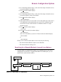
Remote Configuration Options .....................................................................
Setting a Remote Modem's Leased Line Address ....................................
Searching for a Remote Modem's Leased Line Address ..........................
Setting or Searching for a Remote Modem's Leased Line Address .........
Performing Numeric Entry ............................................................................
viii
2-2
2-3
2-5
2-6
2-8
2-9
2-10
2-13
2-14
2-15
2-16
2-17
2-17
2-18
2-18
2-18
2-19
2-19
2-20
2-20
2-20
2-23
2-24
2-24
2-25
2-26
2-27
2-28
2-29
2-30
2-31
2-33
2-33
2-34
2-35
2-35
2-36
2-36
2-37
2-40
2-41
2-43
2-45
Contents (continued)
Chapter 3. Automatic Calling Interfaces
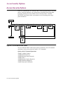
Introduction ..................................................................................................
V.25 bis ACU ................................................................................................
Call Establishment Methods .....................................................................
Modem Configuration ..............................................................................
Addressed Mode........................................................................................
V.25 bis Commands .............................................................................
V.25 bis Responses ...............................................................................
Call Failure Responses .........................................................................
Call Progress Responses ......................................................................
Result Code Responses .........................................................................
Reliable Connection Response .............................................................
Programming Guide for the V.25 bis Auto-Call Unit (ACU) ...................
Asynchronous Frame Format ...............................................................
Synchronous Bit-Oriented Frame Format ............................................
Synchronous Character-Oriented Frame Format .................................
V.25 bis Control Signaling in Addressed Mode .......................................
Idle Condition ......................................................................................
Dialog State...........................................................................................
Connecting State ..................................................................................
Data State .............................................................................................
Disconnecting ......................................................................................
Direct Mode...............................................................................................
Direct Answering .................................................................................
Direct Dialing........................................................................................
Manual Answering and Dialing.................................................................
Manual Answering ................................................................................
Manual Dialing .....................................................................................
LPDA2 Command Set ...................................................................................
How to Configure for LPDA2 ACU ..........................................................
LPDA2 ACU Control Commands ............................................................
LPDA2 Message Format ...........................................................................
Information Field Format and Command .................................................
Header (H) ...........................................................................................
Identifier (I)...........................................................................................
Modem Address (A)..............................................................................
Command Code (C) ..............................................................................
Data Field (D) ......................................................................................
Information Field Format and Response ...................................................
Header (H) Response Field ..................................................................
Identifier Field (I)..................................................................................
Modem Address (A) .............................................................................
Command Code (C) .............................................................................
Sense Byte (SB) ...................................................................................
Data Field (D) ......................................................................................
Framing Rules ...........................................................................................
LPDA2 Dial Command ............................................................................
Dial Command Sense Bytes .................................................................
Dial Response Data Field .....................................................................
3-3
3-3
3-6
3-6
3-7
3-7
3-10
3-11
3-12
3-12
3-13
3-13
3-14
3-15
3-16
3-17
3-17
3-18
3-18
3-19
3-19
3-20
3-20
3-20
3-20
3-21
3-21
3-22
3-22
3-22
3-23
3-23
3-24
3-24
3-24
3-24
3-24
3-25
3-25
3-25
3-26
3-26
3-26
3-26
3-27
3-27
3-30
3-31
ix
Contents (continued)
Chapter 3. Automatic Calling Interfaces (Continued)
LPDA2 Disconnect Command ..................................................................
Disconnect Command Sense Byte ........................................................
Disconnect Response Data Field ..........................................................
Using an External Auto-Call Unit (Bell 801C or Codex 2207).....................
To Initiate a Call... ................................................................................
To Terminate a Call...............................................................................
3-31
3-31
3-32
3-33
3-33
3-33
Chapter 4. Testing Your Modem
Introduction ..................................................................................................
Quick Checks ................................................................................................
Automatic Self-Test ......................................................................................
Starting the Automatic Self-Test ..............................................................
Handling Error Messages .........................................................................
System Testing...............................................................................................
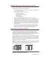
326XFAST Synchronous Data Compression Testing ..............................
Local Analog Loopback Test (AT&T1).....................................................
Local Analog Loopback Pattern Test (AT&T8) .......................................
Remote Digital Loopback Test (AT&T6) .................................................
Remote Digital Loopback Pattern Test (AT&T7) ....................................
Data Mode Pattern Test ............................................................................
Local Digital Loopback (AT&T3) ............................................................
Busy Out (ATH1) .....................................................................................
Retrain (AT01) ..........................................................................................
326XFAST DTE Cable Diagnostics ........................................................
4-2
4-2
4-2
4-3
4-3
4-4
4-5
4-5
4-8
4-10
4-12
4-14
4-16
4-18
4-19
4-20
Chapter 5. Specifications
Introduction ..................................................................................................
Physical Characteristics ................................................................................
Operating Mode Characteristics ...................................................................
Telephone Line Type ................................................................................
FAST Modulation Mode ..........................................................................
V.32 bis Modulation Mode .......................................................................
V.32 Modulation Mode ............................................................................
V.22 bis Modulation Mode .......................................................................
V.22 Modulation Mode .............................................................................
Bell 212 Modulation Mode ......................................................................
V.21 Modulation Mode .............................................................................
Bell 103 Modulation Mode ......................................................................
Environmental Limits ...................................................................................
Primary Power Requirements .......................................................................
Transmitter ....................................................................................................
Output Level..............................................................................................
Transmitter Timing....................................................................................
x
5-2
5-2
5-2
5-2
5-2
5-2
5-3
5-3
5-3
5-3
5-4
5-4
5-4
5-4
5-5
5-5
5-5
Contents (continued)
Appendix A. ASCII/EBCDIC Hexadecimal Equivalents
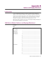
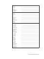
Appendix B. Options and Displays Worksheet
Index
xi
Chapter 1
AT Commands
Contents
AT, AT& and AT Command Descriptions .................................................
Selecting Options and Settings .................................................................
ATD (Dialing an Unstored Telephone Number) ...........................................
ATDS, AT DS (Dialing a Stored Telephone Number) ...............................
ATE (Asynchronous Echo) ...........................................................................
ATH (Busy Out Test) ....................................................................................
ATL (Speaker Volume) .................................................................................
ATM (Speaker Control) .................................................................................
ATO1 (Retrain) .............................................................................................
ATP, ATT, AT PT (Dial Type) .....................................................................
ATQ (Result Codes) ......................................................................................
ATS (S-Register)............................................................................................
ATT (Dial Type) ............................................................................................
ATV (Result Code Format) ...........................................................................
ATX (Call Progress) .....................................................................................
ATY (Longspace Disconnect) ......................................................................
ATZ (Selecting an Option Set) ......................................................................
AT& Commands ...........................................................................................
AT&C (DCD Control) ...................................................................................
AT&D (DTR Control) ..................................................................................
AT&F (Reinitialize Memory) ........................................................................
AT&G (Guard Tone) .....................................................................................
AT&I (Display Modem ID) ..........................................................................
AT&J (Dial Line Jack Types) ........................................................................
AT&L (Line Type) ........................................................................................
AT&M (AT Data Format) .............................................................................
AT&P (Pulse Cycle) ......................................................................................
AT&R, AT CT (CTS Control) ....................................................................
AT&S, AT MR (DSR Control) ...................................................................
AT&T (Test) ..................................................................................................
AT&T4, AT&T5 (Accept RDL) ....................................................................
*
*
*
*
*
1-5
1-8
1-10
1-10
1-11
1-11
1-11
1-12
1-12
1-13
1-13
1-14
1-14
1-14
1-15
1-18
1-18
1-19
1-19
1-20
1-22
1-22
1-23
1-24
1-25
1-26
1-27
1-28
1-29
1-30
1-31
AT Commands 1-1
Contents (continued)
AT&V, AT ST (Modem Status Display)......................................................
Operating Status Messages .......................................................................
DTE Rate/Status Summary ......................................................................
Error-Correction and Data-Compression Status........................................
Transmit and Receive Throughput and Link Utilization Status Display ..
EIA/TIA 232-D (CCITT V.24) Signal Status ...............................................
Status Summary Line ...............................................................................
Display Modem ID ...................................................................................
CQMS Parameter Status ...........................................................................
AT&W (Save Changes: Creating New Option Sets) .....................................
AT&X (Clock) ..............................................................................................
AT&Y (Power Up in Option Set) .................................................................
AT&Z, AT CN (Enter Telephone Numbers) ...............................................
AT Commands ...........................................................................................
AT AA (Answer) ........................................................................................
AT AP (Adaptive Rate) ..............................................................................
AT AS (Answer in Restoral) ......................................................................
AT AY (Auto Type) ....................................................................................
AT BD (Blind Dial) ....................................................................................
AT BK (Break Handling) ...........................................................................
AT CA (Answer/Originate Mode)...............................................................
AT CD (DCD Loss Disconnect)..................................................................
AT CM (Connect Message).........................................................................
AT CN, AT&Z (Entering Telephone Numbers) .........................................
AT CT, AT&R (C, TS) ................................................................................
AT DA (Default Dialing) ............................................................................
AT DB (Buffer Delay) ................................................................................
AT DC (Data Compression) .......................................................................
AT DD (Dial Wait) .....................................................................................
AT DE (DTE Rate)......................................................................................
AT DF (Data Format) .................................................................................
AT DI (Leased to Dial Option) ...................................................................
*
*
*
*
*
*
*
*
*
*
*
*
*
*
*
*
*
*
*
*
1-2 AT Commands
*
1-31
1-32
1-34
1-35
1-36
1-37
1-38
1-41
1-41
1-45
1-47
1-47
1-48
1-49
1-49
1-50
1-51
1-52
1-52
1-53
1-53
1-54
1-54
1-54
1-54
1-55
1-56
1-57
1-57
1-58
1-59
1-59
Contents (continued)
AT
AT
AT
AT
AT
AT
AT
AT
AT
AT
AT
AT
AT
AT
AT
AT
AT
AT
AT
AT
AT
AT
AT
AT
AT
AT
AT
AT
AT
AT
AT
AT
(RTS/CTS Delay) ...........................................................................
*DL
DP (Pause Delay) .................................................................................
*DR (Auto Redial) .................................................................................
*DS, ATDS (Dial a Stored Telephone Number) .....................................
*DT (DTR Delay) ..................................................................................
*EC (Error Correction) ...........................................................................
*FC (Fast Call) ........................................................................................
*FL (Flow Control) ................................................................................
*HD (Hold Dial Line) ............................................................................
*LA (DTE Circuit 141) ...........................................................................
*LC (Line Compensation).......................................................................
*LD (DTE Circuit 140) ...........................................................................
*LE (Dial to Leased Option, Automatic Disconnect) ............................
*LL (Local Analog Loopback Test Busy Out) .......................................
*LN (Link Telephone Numbers) .............................................................
*LS (Low Speed) ....................................................................................
*LT (DTE Pin 25) ...................................................................................
*MD (PSTN Signaling) ..........................................................................
*MF (Modem Flow Control) ..................................................................
*MM (Modulation Mode) ......................................................................
*MN (Minimum Rate) ...........................................................................
*MR, AT&S (DSR Control) ...................................................................
*MS (AT Messages) ...............................................................................
*MX (Maximum Rate) ...........................................................................
*NB (Buffer Option) ..............................................................................
*NC (Network Compensation)................................................................
*ND (View Stored Telephone Numbers) ...............................................
*OC (External Control) ..........................................................................
*OP (External Option Set Select) ...........................................................
*OS (Overspeed) ....................................................................................
*PE (Enable/Disable Password Protection) ...........................................
*PF (Set Protection) ...............................................................................
*
1-60
1-60
1-61
1-61
1-61
1-62
1-63
1-64
1-66
1-68
1-68
1-69
1-69
1-70
1-70
1-71
1-72
1-72
1-74
1-74
1-76
1-76
1-76
1-77
1-77
1-78
1-78
1-79
1-79
1-80
1-80
1-80
AT Commands 1-3
Contents (continued)
AT PN (Unlock Password Protection).........................................................
AT PT (Dial Type) ......................................................................................
AT PW (Change Password) ........................................................................
AT RA (Remote Access) ............................................................................
AT RC (Initiate, Terminate, or Abort Remote Configuration Session) ......
Initiating a Remote Configuration Session with a Dial Modem ..............
Initiating a Remote Configuration Session with a Leased Line Modem ..
Terminating a Remote Configuration Session ..........................................
Aborting a Remote Configuration Session ...............................................
AT RE (Initiate/Terminate Restoral) ..........................................................
AT RP (Parity) ............................................................................................
AT RS (RTS Control) .................................................................................
AT RT (Auto Retrain) .................................................................................
AT SC (Speed Conversion) ........................................................................
AT SI (DTE Inactivity) ...............................................................................
AT SL (Error Correction ID).......................................................................
AT SM (Data Transfer Mode) ....................................................................
AT SR (RTS/DCD Remote Signaling) .......................................................
AT ST, AT&V (Modem Status Display) ....................................................
AT TD (Throughput Delay Minimization) .................................................
AT TL (Tone Length) .................................................................................
AT TT (Call Timeout) .................................................................................
AT XC (Error Correction Reliable Messages) ...........................................
AT ZC (Callback Feature)...........................................................................
AT ZD (Dial Restricted) .............................................................................
AT ZI (Enter Access Security Group Password) ........................................
AT ZP (Select Tones with Access Security) ...............................................
AT ZR (Remote Number Required) ...........................................................
AT ZS (Simulated Ringback) ......................................................................
AT ZV (Password Verification) ..................................................................
*
*
*
*
*
*
*
*
*
*
*
*
*
*
*
*
*
*
*
*
*
*
*
*
*
*
1-4 AT Commands
1-81
1-81
1-82
1-82
1-83
1-83
1-85
1-86
1-86
1-87
1-90
1-91
1-92
1-93
1-93
1-94
1-94
1-96
1-97
1-97
1-98
1-98
1-99
1-100
1-101
1-101
1-102
1-102
1-103
1-103
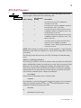
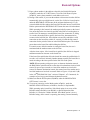
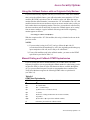
AT, AT& and AT* Command Descriptions
This chapter provides an alphabetic list of the AT commands that you can execute
from the control terminal and the modem front panel.
AT commands and options are described in the following sequence:
*
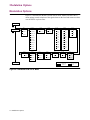
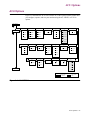
• A pull-out main menu figure (Figure 1-1) illustrating all AT, AT& and AT
command settings, front panel options, and option settings
• A front panel option figure in the left margin describing how to select a
command on the modem front panel
• Industry-standard AT and AT& commands that begin with AT
*
• Motorola-enhanced AT commands, which begin with AT
• A list of the menu's front panel options, if any, that have AT-equivalent control
terminal commands
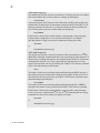
NOTES:
1) For descriptions of front panel options and option settings that do not have AT
command equivalents, see Chapter 2, Front Panel Operation. Chapter 2 is
organized to follow the structure of the front panel menu tree; the main menu
is divided into submenu sections, describing the appropriate options and
settings. For a list of AT commands that do not have front panel equivalents,
see “Non-Configuration AT Commands” in Chapter 5, Using the AT
Automatic Calling Interface, of the 326X Series Modem User’s Guide.
2) Throughout this guide, all references to the 326X Series Modem apply to the
326X V.32 bis, 326XFAST, and 326XFAST-SDC Modems, unless specifically
stated otherwise.
AT Commands 1-5
Figure 1-1. 326X Series Main Menu
1-6 AT Commands
AT Commands 1-7
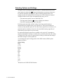
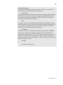
Selecting Options and Settings
The figure in the left margin that precedes each AT command illustrates the mainmenu option, the right-arrow ( ) button indicating that you must press the across
key until the described option appears, and the resulting submenu option. For
example, the first AT command in the following list is ATD, Dialing an Unstored
Telephone Number. In the figure accompanying this entry, you see:
• The main-menu option to access: Data 9600 T/D?
• The front panel control key
to press to display the submenu
• The ATD Command prompt: Enter Then Dial
Each front panel option has a default setting. Some front panel defaults are
determined by the assigned factory-preset option sets. These preset defaults are
exclusive to the particular option set. The other factory options are not exclusive to a
particular option set and they always have the same default setting, regardless of
which factory-preset option set you are using.
For options that belong to option sets, a number or the word “all” in parentheses
appears underneath the selection. A number tells you which option set(s) the setting
is a default for. If the word “all” appears under a setting, it means that the setting is
the default setting for all four option sets.
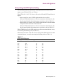
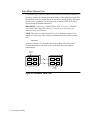
As an example, the option setting portion of the DTR Control (AT&D) option
appears as follows:
Option Setting
High
(1, 4L)
Escape
Discon
(4D)
Reset
Tail
(2)1
108.1
(3)1
108.2
(2, 3)
1Default
1-8 AT Commands
for the 326XFAST-SDC Modem
The defaults for the DTR Control option for the 326X V.32 bis and 326XFAST
modem are:
• High for Option sets 1 and 4 (the “L” next to the 4 indicates that High is the
default for Option Set 4 for leased line modems (models 3261, 3263, 3266,
3268)
• Discon for Option set 4 (the “D” next to the 4 indicates that Discon is the
default for Option set 4 for dial modems (models 3260, 3262, 3265, 3267)
• 108.2 for Option sets 2 and 3
The defaults for the DTR Control option for the 326XFAST-SDC modem are:
• High for Option sets 1 and 4 (the “L” next to the 4 indicates that High is the
default for Option Set 4 for leased line modems (models 3261, 3263, 3266,
3268)
• Tail for Option set 2
• 108.1 for Option set 3
In this example, since High is the default for Option sets 1 and 4L for all products
(326X V.32 bis, 326XFAST, and 326XFAST-SDC), no product-specific distinction is
made. Where one setting (for example, 108.1) is the default for Option set 3 in the
326XFAST-SDC product, a footnote indicates the difference.
Unless specified by a “D” or an “L,” defaults apply to all models. For options that do
not belong to option sets, the default setting is designated by the word “default” in
parentheses underneath the setting.
The following sections describe industry-standard AT commands that begin with AT.
NOTES:
1) The conventions described for identifying front panel option settings and
defaults apply to the 326X V.32 bis, 326XFAST, and 326XFAST-SDC
Modems. Option settings that vary are clearly marked indicating to which
product the default setting applies.
2) Throughout this chapter, AT commands are listed in table format. In the
“AT Command Setting” column, the AT reference has been omitted; however,
be sure to enter the entire AT command. For example:
*
AT ZCO
AT Commands 1-9
D, DS, *DS
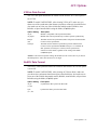
ATD (Dialing an Unstored Telephone Number)
• • •
DATA 9600 T/D?
The ATD (Enter Then Dial) command allows you to dial a telephone number (up to
50 characters) without storing it in your modem's telephone book.
Enter Then Dial
The ATD Command
You can dial a telephone number directly from your keyboard. To do this, enter the
ATD command followed by the telephone number and a carriage return.
For example:
ATD5551234<CR>
The Front Panel
See the "Performing Numeric Entry" section in Chapter 2 of this guide for details on
how to use numeric entry.
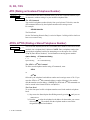
ATDS, AT*DS (Dialing a Stored Telephone Number)
DATA 9600 T/D?
• • •
Dial From #
*
The ATDS and AT DS (Dial From #) commands dial a number stored in one of the
modem's nine “telephone book” addresses. NOTE: Enter a telephone number into
your modem's telephone book before attempting to use this option. See “AT&Z,
AT CN (Enter Phone Numbers)” for information on entering phone numbers.
*
Option Setting
1–9
Option Setting
AT Command Setting
1–9
AT Command Setting
*
The ATDS or AT DS Command
To dial a stored telephone number using AT commands, enter:
ATDS
or
*
AT DS
followed by the telephone book address number and a carriage return <CR>. If you
enter the ATDS or AT DS command without a number following it, the modem
dials the number stored in address 1. NOTE: The ATDS and AT DS commands can
also be entered in the format ATDS=n or AT DS=n.
*
*
*
The Front Panel
To use the front panel to dial a telephone number stored in the modem's telephone
book:
1) Step across the Status/Option Sets/Dialing menu by pressing
until you see:
Dial from #=n
2) Press the
to select the telephone book address for the number you want to
dial and press . The modem dials the telephone number stored in the
designated telephone book address.
1-10 AT Commands
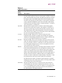
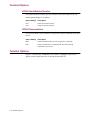
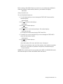
E, H, L
ATE (Asynchronous Echo)
The ATE (Async Echo) command enables the modem to echo all commands received
• • • from an asynchronous DTE.
ACU OPT’S
Async Echo
Option Setting
Off
AT Command
Setting
0
On
1
(all)
Description
The modem does not echo asynchronous
commands to the DTE.
The modem echoes asynchronous commands to
the DTE.
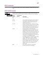
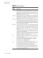
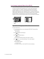
ATH (Busy Out Test)
The ATH command enables you to initiate a Busy Out test.
TEST OPT’S
• • •
Option Setting
Busy Out
Test
AT Command
Setting
1
Description
Makes the modem appear busy to incoming calls.
To configure the modem to use the Busy Out
feature, refer to the AT LT (DTE Pin 25) option
description in this chapter
If Busy Out is enabled, ATH0 will disconnect the
busy out condition. Also, if the modem is in
“escape mode” (the modem has transitioned to
command state from the data state—online or
test), the ATH0 command disconnects the
modem.
*
End Test
0
Refer to Chapter 4, of this guide or the AT&T option description within this chapter,
for a detailed description of how to initiate and terminate the Busy Out test.
ATL (Speaker Volume)
The ATL (Volume) option sets the speaker volume in the modem.
TELCO OPT’S
• • •
Volume
Option Setting
Medium
AT Command
Setting
2
Description
Medium
(all)
Loud
Soft
3
0,1
Loud
Soft
AT Commands 1-11
M, O1
ATM (Speaker Control)
The ATM (Speaker) option controls the operation of the modem's speaker.
TELCO OPT’S
• • •
Speaker
Option Setting
Dialing
AT Command
Setting
1
(all)
On
Security
2
3
Off
0
Description
The speaker comes on while dialing and training
but stays off when the modem enters data mode.
The speaker is always on.
The speaker goes on when dialing is completed
and goes off when the modem enters data mode.
The speaker is always off.
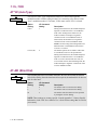
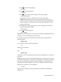
ATO1 (Retrain)
TEST OPT’S
• • •
Test
ATO1 allows you to return to data mode and initiate a retrain with the remote
modem. Refer to Chapter 4, Testing Your Modem, or the AT&T option description
within this chapter for a description of how to initiate a retrain.
Option Setting
Retrain
1-12 AT Commands
AT Command
Setting
0
1
Description
Return to data mode.
Allows you to initiate a retrain with the remote
modem.
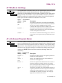
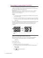
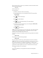
P, T, *PT, Q
ATP, ATT, AT*PT (Dial Type)
DIALING OPT’S
• • •
Dial
*
The ATP, ATT and AT PT (Dial) commands determine how the modem dials
telephone numbers: in tone, pulse, or auto tone/pulse. The modem refers to this
option setting if it does not encounter any T or P modifiers in the telephone number.
Option Setting
Tone
AT Command
Setting
ATT
*
AT PT0
Pulse
ATP
*
AT PT2
*
AT PT1
Auto
Description
The modem uses tone (DTMF) dialing unless
otherwise specified by the T or P dial modifiers
in a telephone number.
The modem uses pulse dialing unless otherwise
specified by the T or P dial modifiers in a
telephone number.
The auto-call unit attempts to tone dial when
initiating a call. If tone dialing is not possible,
pulse dialing is used.
For this feature to work correctly, the first
character in a dial string must be a digit, and not
a dial modifier. A T or P in the dial string
overrides this setting for that dial string.
NOTE: Do not use the Auto setting if you are in
a PBX environment. If a dial tone is detected
after the first digit, the phone number will be
redialed as a pulse which may not be
recognizable by the PBX.
ATQ (Result Codes)
ACU OPT’S
• • •
The ATQ (Rslt Code) command selects whether result codes (including Call
Progress messages) are displayed.
Rslt Code
Option Setting
Enable
AT Command
Setting
0
(all)
Disable
Orig
1
2
Description
Result codes are displayed at the DTE.
Result codes are not displayed at the DTE.
Result codes are output to the DTE only when
operating as an originate modem.
AT Commands 1-13
S, T, V
ATS (S-Register)
Data 9600 T/D?
• • •
S-Reg xxx=nnn
The ATS (S-Reg xxx) command allows you to view and set the various S-Registers
that are supported by the 326X Series Modems. S-Registers contain values that
determine and reflect how the modem operates and executes commands. You can
view and change S-Register values via the AT commands described in this section or
through the front panel option. If an invalid S-Register is entered, the modem
responds with an OK, but no action occurs.
See the "Performing Numeric Entry" section in Chapter 2 for details on how to use
numeric entry to enter the appropriate S-Register. For a full description of
S-Registers, see the “S-Registers” section in Chapter 5 of the 326X Series Modem
User’s Guide.
ATT (Dial Type)
See the ATP command description described earlier.
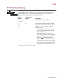
ATV (Result Code Format)
The ATV (RsltForm) command selects the format of result codes that are sent to your
• • • DTE.
ACU OPT’S
RsltForm
Option Setting
Numeric
AT Command
Setting
0
Verbose
1
(all)
1-14 AT Commands
Description
Result codes are sent to your DTE as numbers
(short form).
Result codes are sent to your DTE as full words
(long form). Refer to Appendix A of the 326X
Series Modem User’s Guide for a summary of
result codes.
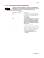
X
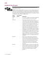
ATX (Call Progress)
The ATX (Call Progress) command determines whether the modem waits for call
ACU OPT’S
• • • progress signals or blind dials when establishing calls.
Call Progress
Option Setting
0
AT Command
Setting
0
1
1
2
2
3
3
4
4
Description
The modem uses only NO CARRIER and
CONNECT result codes.
The modem uses only NO CARRIER, CONNECT,
and CONNECT <Rate> result codes.
The modem waits for dial tone and uses only NO
CARRIER, CONNECT, CONNECT <Rate> and
NO DIALTONE result codes.
The modem detects busy signal and uses only NO
CARRIER, CONNECT, CONNECT <Rate>, and
BUSY result codes.
The modem waits for dial tone and detects busy
signal. Only NO CARRIER, CONNECT,
CONNECT <Rate>, BUSY, and NO DIAL TONE
result codes are used.
NOTE: These settings are country-specific. Consult Appendix C, Country-Specific
Information, in the 326X Series Modem User’s Guide for the settings that are valid in
your country.
The following section discusses how each ATX (Call Progress) command setting
works.
ATX0 or 1 (Call Progress=0 and 1)
The modem goes off-hook, waits for the amount of time specified by the Blind Dial
option, and blind dials whether or not dial tone is present. After processing all of the
characters in the dial string, including dial modifiers, the modem looks for data
carrier for the amount of time specified by the AT TT (Call Timeout) command.
If the modem does not detect data carrier before the time specified by the AT TT
(Call Timeout) command expires, it hangs up and displays:
*
*
NO CARRIER
If the modem does detect data carrier, it displays either:
CONNECT
(for setting 0) or a speed-specific connect message (for setting 1). If your modem is
using error correction and the AT XC1 or AT XC2 (Rel Msg=Short or Long)
command, the modem also displays the suffix:
*
*
RELIABLE
or
RELIABLE EC=(xxx) DC=(yyy)
AT Commands 1-15
X
ATX2 (Call Progress=2)
The modem goes off-hook and looks for dial tone. If it detects dial tone, the modem
dials. If the modem does not detect dial tone, it hangs up and displays:
NO DIALTONE
After processing all of the characters in the dial string, including dial modifiers, the
modem looks for data carrier for the amount of time specified by the AT TT (Call
Timeout) command. If data carrier is not detected before the time specified by the
Call Timeout option expires, the modem hangs up and displays:
*
NO CARRIER
If data carrier is detected, the modem displays a speed-specific connect message.
If the modem is configured for error correction, and AT XC1 or AT XC2
(Rel Msg=Short or Long)) is selected, the modem also displays the suffix:
*
*
RELIABLE
or
RELIABLE EC=(xxx) DC=(yyy)
ATX3 (Call Progress=3)
The modem goes off-hook, waits for the amount of time specified by the AT BD
(Blind Dial) command, and then blind dials. After processing all of the characters in
the dial string, including dial modifiers, the modem starts the AT TT (Call Timeout)
command timer and looks for a busy signal, ringback, and data carrier. If a busy
signal is detected before the time specified by the AT TT (Call Timeout) command
expires, the modem hangs up and displays:
*
*
*
BUSY
The length of time between finishing dialing and displaying the BUSY message is
the amount of time the modem takes to detect the busy signal. If data carrier is not
detected before the time specified by the AT TT (Call Timeout) command expires,
the modem hangs up and displays:
*
NO CARRIER
The length of time between finishing dialing and displaying the NO CARRIER
message is the amount of time specified by the AT TT (Call Timeout) command.
If data carrier is detected, the modem displays a speed-specific connect message.
If error correction is enabled and AT XC1 or AT XC2 (Rel Msg=Short or Long)
commands are selected, the modem also displays the suffix:
*
RELIABLE
or
RELIABLE EC=(xxx) DC=(yyy)
1-16 AT Commands
*
*
X
ATX4 (Call Progress=4)
The modem goes off-hook and looks for dial tone. If a dial tone is detected, the
modem dials. If not, the modem hangs up and displays:
NO DIALTONE
After processing all of the characters in the dial string, including dial modifiers, the
modem looks for a busy signal, ringback, and data carrier. If the modem detects a
busy signal before the time specified by the AT TT (Call Timeout) command
expires, the modem hangs up and displays:
*
BUSY
The length of time between finishing dialing and displaying the BUSY message is
the amount of time it takes the modem to detect the busy signal. If the modem does
not detect data carrier before the time specified by the AT TT (Call Timeout)
command expires, the modem hangs up and displays:
*
NO CARRIER
The length of time between finishing dialing and displaying the NO CARRIER
message is the amount of time it takes the modem to detect ringback, plus the
amount of time specified by the AT TT (Call Timeout) command. If data carrier is
detected, the modem displays a speed-specific connect message. If the modem is
configured for error correction and AT XC1 or AT XC2 (Rel Msg=Short or Long),
the modem displays the suffix:
*
*
*
RELIABLE
or
RELIABLE EC=(xxx) DC=(yyy)
AT Commands 1-17
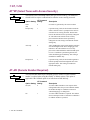
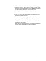
Y, Z
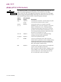
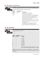
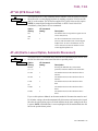
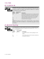
ATY (Longspace Disconnect)
The ATY (Longspace) command enables the long-space disconnect function. Refer
• • • to the AT MD command.
MODULATIONOPT’S
*
Longspace
Option
Setting
Off
AT Command
Setting
0
(all)
On
1
Description
The modem does not disconnect when it receives
space that exceeds 1.6 seconds in duration. When
terminating a call, the modem does not send
continuous space for 4 seconds.
The modem disconnects when it receives space
that exceeds 1.6 seconds in duration. When
terminating a call, the modem sends continuous
space for 4 seconds.
ATZ (Selecting an Option Set)
DATA 9600 T/D?
• • •
Select Options
The ATZ (Select Options) command chooses which of the four option sets, stored in
nonvolatile memory, is used by the modem. When you use Select Options or the ATZ
command, the new option set takes effect immediately. For a description of each
action set, see Chapter 4, Configuring Your Modem, in the 326X Series Modem
User’s Guide.
Option
Setting
1
2
3
4
AT Command
Setting
0, 1
2
3
4
Modem Uses
Option Set 1
Option Set 2
Option Set 3
Option Set 4
NOTE: The modem disconnects from the line when the ATZ command is entered.
Also, any test in progress is immediately terminated. Since any AT command that
follows the ATZ command is ignored by the modem, make sure that the ATZ
command is the last one entered in an AT command string. Use the AT&Y command
to select with which option set the modem powers up.
1-18 AT Commands
&C
AT& Commands
The following sections describe industry-standard AT commands that begin with
AT&.
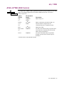
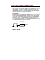
AT&C (DCD Control)
TERMINAL OPT’S
• • •
DCD
The AT&C (DCD) command determines how the modem sets the DCD signal. The
modem signals the DTE with DCD on EIA/TIA 232-D Pin 8 (V.24 Circuit 109).
Option
Setting
High
AT Command
Setting
0
(1)
Normal
1
(2, 3, 4)
ACU On
2
Remote
3
Description
DCD is always on.
DCD is off during dialing and also while the modem is
training with the remote modem. DCD is on in data
mode. When the modem is disconnected from the
telephone line, DCD is off.
DCD is on when the modem is disconnected so that
terminals requiring this signal can use the ACU. During
dialing, DCD goes off until both local and remote
modems train and are ready to pass data. DCD is on in
data mode. DCD drops on a disconnect momentarily.
This setting applies to simulated half-duplex
applications and works only if the remote modem also
supports RTS/DCD signaling. When the remote DTE
turns RTS on, DCD is forced on at the local modem. The
local modem can receive data only during this period.
Once the remote DTE drops RTS, DCD at the local
modem follows. The Rem RTS/DCD option allows you
to choose the type of RTS/DCD signaling.
For the Remote setting to work properly, set the remote
modem's AT RS (RTS) command to AT RS2
(Remote). Also, make certain that the Direct data
transfer mode is in use, and that neither the V.21 nor the
Bell 103 modulation mode is in use. If the direct data
transfer mode is not in use, or the V.21 or Bell 103
modulation mode is in use, DCD behaves as if
DCD=Normal.
DCD is always on; however, it will drop after
disconnect and remain low momentarily.
*
Wink
4
*
AT Commands 1-19
&D
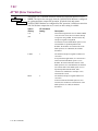
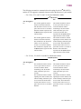
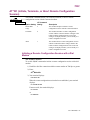
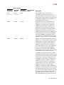
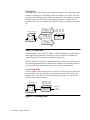
AT&D (DTR Control)
The AT&D (DTR) command determines how the modem interprets the DTR signal.
TERMINAL OPT’S
• • • The local DTE uses DTR (Pin 20) to signal the modem.
DTR
326X V.32
bis Modem
High (1, 4L)
Option Setting
326XFAST 326XFASTAT Command
Modem
SDC Modem Setting
High (1, 4L) High (1, 4L)
0
Escape
Escape
Escape
1
Discon (4D)
Discon (4D) Discon
2
Reset
Reset
3
Reset
Description
The modem ignores DTR from the DTE. The
modem reads DTR as always high. Use this setting
if the DTE does not provide DTR, or if you plan to
use DTR/CTS flow control with the errorcorrection feature.
When ACU Select=AT and AT Fortbm=Async
(AT&M), the modem enters the AT escape mode
when an on-to-off DTR transition is detected while
modem is in data or test mode.
The modem hangs up and enters command mode
when an on-to-off DTR transition is detected, while
the modem is in data, test, or escape mode. If DTR
is low, the modem does not auto-answer.
This setting is similar to Discon except that an
on-to-off DTR transition also causes the modem to
reinitialize its memory (the equivalent of executing
the ATZ command). If DTR is low, the modem
auto-answers.
The option set to which the modem resets is
determined by AT&Y (Power Up In option). If the
AT&Y (Power Up In) command is set for 1, 2, 3, or
4, the designated option set is loaded. If Old is
selected, the currently selected option set is
reloaded.
If DTR is dropped during a test (such as RDL,
LAL, LDL, RDL Pattern, etc.), the modem
disconnects from the line and resets memory to the
selected option set.
NOTE: A reset can change the value of the AT&D
(DTR) command setting from Reset to another
setting.
1-20 AT Commands
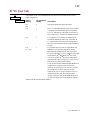
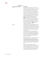
&D
Option Setting
326X V.32
326XFAST 326XFASTAT Command
bis Modem
Modem
SDC Modem Setting
Tail
Tail
Tail
4
(2)1
108.1
108.1
108.1
5
(3)
Description
This setting is similar to 108.1 except that the
modem auto-answers an incoming call even if DTR
is off. Use the Tail option if you plan to use the
modem in a tail circuit to a high-speed leased line
modem or to other devices using DTR and DSR.
When DTR transitions from off to on, the modem
connects to the telephone line and dials if the
Default Dial option is enabled. Use the Tail option
if you have an intelligent terminal which must dial
out and answer calls without continually
monitoring for a ringing signal.
The DTR signal emulates the function of the Talk/
Data ( at the Home position) key on the modem
front panel. An off-to-on DTR transition instructs
the modem to connect to the telephone line. If the
modem detects an incoming call, the call is
connected. If the modem does not detect an
incoming call and you have enabled the AT DA
(Default Dial) command, the modem dials the
number specified. If the AT DA (Default Dial)
command is disabled, the modem refers to the
AT MM (Modulation Mode option in the
MODULATION OPT'S menu.) If set to answer, the
modem goes off-hook and sends an answer-back
tone. An on-to-off DTR transition disconnects the
modem from the telephone line. If DTR is low, the
modem does not
auto-answer.
When the modem is disconnected from the
telephone line and the DTE turns DTR on, the
modem responds to all V.25 bis and all AT
commands. When the DTE turns DTR off, the
modem does not respond to dialing and answering
AT commands, but responds to all other AT
commands. Also with DTR off, the modem ignores
all V.25 bis commands. The DTR signal must
remain on throughout the course of a connection.
An on-to-off DTR transition disconnects the
modem from the telephone line. If DTR is low, the
modem does not auto-answer.
*
*
*
108.2
108.2
(2, 3)
(2, 3)
108.2
6
AT Commands 1-21
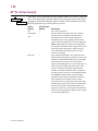
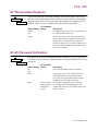
&F, &G
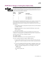
AT&F (Reinitialize Memory)
• • • The AT&F (Reinit Memory?) command is used to reset your modem to the factory-
DATA 9600 T/D?
default option settings. The four factory default option sets are restored, and all
stored telephone numbers are deleted.
Reinit Memory?
The AT&F Command
Enter:
AT&F<CR>
The modem front panel displays:
326x Initial
and the terminal displays:
OK
The factory-programmed option sets are now in place.
The Front Panel
When you press
the modem first asks you:
Reinit All Mem?
Be sure you want to reinitialize the modem's memory before you press
The modem displays:
again.
326x Initial
indicating that the original factory-programmed option sets are now in place.
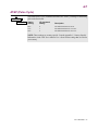
AT&G (Guard Tone)
The AT&G (Guard Tone) command determines what type of guard tone the modem
MODULATIONOPT’S
• • • uses in V.22 bis operation. The proper guard tone (AT&G) option setting is required
Guard Tone
by your PTT. Leave this option set to Off unless your PTT requires the use of guard
tone.
Option Setting
Off
550
1800
AT Command
Setting
0
1
2
Description
The modem does not use a guard tone.
The modem uses a guard tone of 550 Hz.
The modem uses a guard tone of 1800 Hz.
NOTE: These settings are country-specific. Consult Appendix C, Country-Specific
Information, in the 326X Series Modem User’s Guide for the settings that are valid in
your country.
1-22 AT Commands
&I
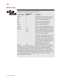
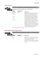
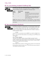
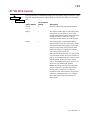
AT&I (Display Modem ID)
DATA 9600 T/D?
• • • The AT&I (Display Modem ID) command allows you to view on your control
DTE 19.2 RELIABL
terminal screen non-action information that identifies your modem. This information
is referred to as the short form status snapshot display.
The following command option list describes short form modem identification
information.
AT Command Setting
0
1
2
3
4
5
Description
Software part number
Factory product code
Country code
Product code
Network control address (optional)
Serial number
The Front Panel
You can also view modem status snapshot by using the front panel. Press
until
DTE 19.2 RELIABL appears, and press
until Display Modem Id appears.
AT Commands 1-23
&J
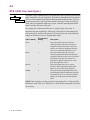
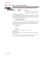
AT&J (Dial Line Jack Types)
TELCO OPT’S
Telco
The AT&J (Telco) command allows you to make the correct registered jack selection
• • • that is compatible with your equipment. The Federal Communications Commission
(FCC) is a telecommunications and standards organization that specifies a series of
registered jacks for use with a dial line network (sometimes referred to as PSTN).
These jacks are designated as RJxxx-type jacks, where RJ means Registered Jack
and xxx specifies the series of the jack.
For example, RJ11 indicates that the jack is a registered jack from series 11.
Sometimes the jack designation is followed by a letter (RJ11C) that indicates the
jack housing style. Jacks specified under FCC Part 68 fit into one of the following
categories: Permissive (voice) or Programmable (data).
Option Setting
RJ11C
AT Command
Setting
0
RJ45S
2
RJ16CS
3
RJ4MB
4
Description
This 6-pin modular jack type is the most
common permissive data mode (voice) jack
arrangement found in the home or office and
operates on a single-line bridged tip-and-ring
voice or low-speed data application service.
This 8-pin modular jack type is the most
common programmable data mode (data) jack
arrangement and permits the use of an exclusionkey telephone. This jack also operates on a
single-line bridged tip-and-ring voice or lowspeed data application service.
This 6-pin modular jack type is a special
permissive data mode jack arrangement that
allows use of an exclusion-key telephone.
This 8-pin modular programmable data mode
jack arrangement supports Make Busy operation.
Using this jack type, you can make the modem
appear to be off-hook to the central telephone
office.
NOTE: These settings are country-specific.Consult Appendix C, Country-Specific
Information, in the 326X Series Modem User’s Guide for the settings that are valid in
your country.
1-24 AT Commands
&L
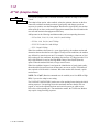
AT&L (Line Type)
MODULATIONOPT’S
Line
The AT&L (Line) command sets the type of telephone line used by the modem. If
• • • you change this option while the modem has a dial-line connection, the change does
not take effect until you disconnect the line. When the modem is configured for any
one of the AT RE option settings except 108.ACU or 116.ACU, if a call fails, the
originating modem disconnects from the dial line and returns to the leased line
unless the Auto Redial or Link Phone # options are enabled.
*
Option
Setting
Dial
AT Command
Setting
0
(1, 2, 3, 4D)
2W Lease
1
(4L)
4W Lease
2
Description
The modem communicates over dial lines in dial
applications only.
The modem communicates over a 2-wire leased line.
The ACUs (AT and V.25 bis) are not functional when
the modem is connected to a leased line.
The modem communicates over a 4-wire leased line.
The ACUs (AT and V.25 bis) are not functional when
the modem is connected to a leased line.
AT Commands 1-25
&M
AT&M (AT Data Format)
The AT&M (AT Form) command determines the format of data when the ACU
ACU OPT’S
• • • Select option is set to AT.
AT Form
NOTE: To enable 326XFAST-SDC (if not using one of the predefined option sets),
once you have selected the AT ACU, make sure you select one of the synchronous
data formats (Sync Data, DTR Dial, or Man Dial) described below. Also make sure
you select one of the reliable data transfer modes (Reliable, Auto Reliable, or Speed
Auto Reliable) using the Mode (AT SM) option.
*
Option
Setting
Async
AT Command
Setting
0
(all)
Sync Data
1
Description
The modem is compatible with asynchronous DTEs and
uses the AT command set and auto-call functions.
This setting is intended for terminals capable of
communicating either synchronously or asynchronously
over the same serial port. When disconnected from the
dial line, communication between the modem and DTE is
asynchronous. The AT command set and auto-call
functions are used to establish calls. Once in data mode,
the modem exchanges data synchronously with the
remote modem. An on-to-off DTR transition causes the
modem to disconnect from the dial line. This option is
designed for use with the AT DT (DTR Delay option in
the TERMINAL OPT'S menu) command. The AT DT
command controls the length of time that your modem
holds DTR high (the amount of time you have to switch
from an asynchronous to a synchronous terminal). If
DTR transitions from on to off while you are switching to
a synchronous terminal, your modem disconnects from
the dial line.
When an off-to-on DTR transition is detected, the
modem automatically dials the number stored in the
memory location designated by the Default Dial option
setting. Once connected, the modems transmit data
synchronously. If DTR transitions from on to off, the
modem hangs up and returns to the asynchronous
command mode. If DTR is low, the modem does not
auto-answer.
DTR signals toggle between talk and data modes. With
DTR off, numbers can be dialed from a telephone. Once
an answer tone is heard, the telephone is hung up, and
DTR is raised; the modems connect and send data
synchronously. If DTR is dropped, the modems
disconnect.
*
1-26 AT Commands
DTR Dial
2
Man Dial
3
*
&P
AT&P (Pulse Cycle)
DIALING OPT’S
Pulse Cycle
The AT&P (Pulse Cycle) command determines the “make” percentage of the dialing
• • • pulse make/break ratio.
Option
Setting
40%
33%
38%
AT Command
Setting
0
1
2
Description
The make/break ratio is 40:60.
The make/break ratio is 33.5:66.5.
The make/break ratio is 38.5:61.5.
NOTE: These settings are country-specific. Consult Appendix C, Country-Specific
Information, in the 326X Series Modem User’s Guide for the settings that are valid in
your country.
AT Commands 1-27
&R, *CT
AT&R, AT*CT (CTS Control)
*
The AT&R and AT CT (CTS) commands determine how the modem sets the CTS
TERMINAL OPT’S
• • • signal. The modem signals the DTE with the CTS on EIA/TIA 232-D Pin 5
CTS
(V.24 Circuit 106). The CTS signal discussed below is the state of the CTS signal
after the setting of the modem's RTS option has been followed. In order for CTS to
follow the RTS signal from the DTE, set the RTS option to Normal.
Option
Setting
High
AT Command
Setting
AT CT0
Normal
AT&R1
AT CT1
(2, 3, 4)
ACU On
AsynSync
(1)
RTS
*
*
*
AT CT3
*
AT CT2
AT&R0
*
AT CT4
Description
CTS remains on at all times. Use this setting if you plan
to use RTS/CTS or DTR/CTS flow control.
The modem controls CTS as required in normal
handshaking. For V.25 bis ACU operation, CTS follows
DTR in command state; CTS is off during training/
retraining and follows RTS in data mode. For AT ACU
operation, CTS follows RTS in command state; CTS is
off in training/retraining and follows RTS in data mode.
If an ACU is not selected, CTS is low.
CTS is on in ACU mode, goes off during training/
retraining, and follows RTS in data mode.
CTS is on in asynchronous mode.
CTS is off in synchronous, ACU mode. If the data
transfer mode is synchronous, CTS is off during training/
retraining and follows RTS in data mode. When CTS
follows RTS in data mode, the setting of the RTS/CTS
Delay option applies (if Mode=Direct).
CTS follows RTS. Use this selection if your application
requires CTS to immediately follow RTS.
When CTS=RTS, the RTS/CTS Delay (AT DL) option
is not available. If one of these flow control methods is
used: Flow=RTS/CTS or Flow=DTR/CTS, then CTS
does not follow RTS in a flow-off condition.
*
1-28 AT Commands
&S, *MR
AT&S, AT*MR (DSR Control)
*
TERMINAL OPT’S
DSR
The AT&S and AT MR (DSR) commands determine how the modem sets the DSR
• • • signal. The modem signals the DTE with the DSR on EIA/TIA 232-D Pin 6
(V.24 Circuit 107).
Option
Setting
High
AT Command
Setting
AT MR1
(1)
Normal
AT&S0
AT MR0
(3, 4)
AT&S1
*
*
(2)1
DTR
Drop on Disc
Description
DSR is always on.
DSR is controlled by the modem. DSR is on
when the modem recognizes that it is
communicating with a compatible modem.
*
*
AT MR2
AT MR3
DSR follows DTR.
The same as the Normal setting except that when
a disconnection is initiated from the local end,
(2)
DSR is dropped immediately.
The same as the DTR setting except DSR is
Sim LL
AT MR4
dropped when the remote modem requests a
disconnect.
1 Default with the 326XFAST-SDC Modem
*
AT Commands 1-29
&T
AT&T (Test)
TEST OPT’S
• • •
The AT&T (Test) command is used to initiate and terminate tests. See Chapter 4 of
this guide for a complete description of each test.
TEST
Option Setting
End Test
(all)
LAL
RDL
LDL
Pattern
LAL Pat
RDL Pat
Busy Out
AT Command
Setting
0
1
6
3
8
7
ATH1
ATH0
Retrain
ATO1
Description
Ends the test currently in progress for each
test listed below (except for the Retrain test).
Initiates a local analog loopback test.
Initiates a remote digital loopback test.
Initiates a local digital loopback test.
Initiates an end-to-end pattern test.
Initiates a local analog loopback pattern test.
Initiates a remote digital loopback pattern test.
Makes the modem appear busy to incoming
calls. To configure the modem to use the Busy
Out feature, refer to AT LT (DTE Pion 25)
option description in this chapter.
*
If Busy Out is enabled, ATH0 will disconnect
the busy out condition. If the modem is in
“escape mode” (the modem has transitioned
to command state from the data state—online
or test), the ATH0 command disconnects the
modem. Selecting End Test will also
disconnect the busy out condition.
Initiates a retrain with the remote modem.
NOTES: (1) For maximum reliability, run the RDL, LDL, and RDL Pat tests at a data rate
of 19.2 kbps or lower. (2) These settings are country-specific. Consult Appendix C,
Country-Specific Information, in the 326X Series Modem User’s Guide for the
settings that are valid in your country. (3) When operating in the 326XFAST-SDC mode,
the modem fallsback to Direct mode (Mode=Direct) to run “on-line” loopback tests. Refer
to “326XFAST Synchronous Data Compression Testing” in Chapter 4, Testing Your
Modem, for additional information.
1-30 AT Commands
&T4, &T5, &V, *ST
AT&T4, AT&T5 (Accept RDL)
The AT&T4 and AT&T5 (Accept RDL) commands control whether the local modem
TEST OPT’S
• • • can be placed in a remote digital loopback test by a remote modem.
Accept RDL
Option
Setting
On
(all)
Off
AT Command
Setting
4
5
Description
The local modem can be put into a remote digital
loopback test.
The modem cannot be put into a remote digital
loopback test.
AT&V, AT*ST (Modem Status Display)
*
The AT&V and AT ST (Modem Status) commands allow you to view, via your conDATA 9600 T/D?
• • • trol terminal, modem status information in either long or short form, using the
DTE 19.2 RELIABL
*
AT ST and AT&V commands.
AT Command
Option Setting Setting
DTE/DCE 19.2 0
EC
DC
Tx= kb 0%
Rx= kb 0%
DCD RTS CTS
DSR DTR
AOP DLP ALP
DR=0 TI=0 O D
Display Modem
Id
CQMS
1
Description
Long Form: The AT ST0 and AT&V commands select the long-form status
snapshot display. This display consists of several screens and provides a
summary of: Operating Status; DTE/DCE Rate/Status; Error correction, Data
Compression Status; EIA/TIA 232-D (CCITT V.24) Signal Status, Disconnect
Reasons; display the modem’s software revision (Display Modem ID); and
CQMS Parameter Status. Also, the long-form snapshot summarizes the settings
of all front panel options and their corresponding AT commands (only the suffix
of the AT command is given; the “AT” is omitted), nonconfiguration (action) AT
commands, and the setting of each S-Register. NOTE: Tx= kb 0% is displayed
only for the 326XFAST-SDC Modem.
*
*
Short Form: The AT ST1 and AT&V commands select the short-form status
snapshot display. The short-form display provides a summary of AT command
settings and S-Register values (for a detailed discussion of S-Registers,
see “S-Registers” section in Chapter 5 of the 326X Series Modem User’s Guide.
In short-form, only the suffixes and settings of each nonaction AT command are
shown, and S-Register values are displayed in the following format:
S010:024
This means that S-Register 10 is set to decimal value 24.
The Front Panel. Your front panel provides some or all of the following information:
Operating Status; DTE/DCE Rate/Status; Error Correction, Data Compression, and
Transmit and Receive Throughput and Link Utilization Status; EIA/TIA 232-D
(CCITT V.24) Signal Status; and CQMS Parameter Status.
AT Commands 1-31
&V, *ST
Operating Status Messages
Operating Status messages display the operating status of the modem. NOTE: The
modem automatically displays one of the operating status messages in Table 1-1 if a
front panel key is not pressed within five minutes. The R indicates a restoral
connection and H indicates a hold of the dial line. You can also view Operating
Status messages by pressing
until you reach the Home position.
Table 1-1.
Operating Status Messages
Message
Data <rate>
Data <rate>
R
Data <rate>
H
Dialing
Disconnect
LAL <rate>
LAL Training
Test <rate>
Bad LAL
Busyout
Dial Wait
Link Wait
Redial Wait
Callbk Wait
Ranging
Training
Retraining
Synchronizing
Tone Detect
Disc Wait
Disc/Rx Wait
Disc Tx Wait
Off Hook
WAIT <rate>
1-32 AT Commands
Description
T/D? The modem is transmitting at <rate> bps.
T/D? The modem is in dial restoral mode, and transmitting at
<rate> bps.
T/D? The modem is holding the dial line while it tests the leased
line, and transmitting at <rate> bps.
T/D? The modem is dialing a telephone number.
T/D? The modem is not connected to the telephone line.
T/D? The modem is in a local analog loopback test, at <rate> bps.
T/D? The modem is executing a training sequence for a local analog loopback test.
T/D? The modem is running a test at <rate> bps.
T/D? The modem failed a local analog loopback test.
T/D? The modem appears busy to incoming calls.
T/D? The modem is waiting before dialing a number.
T/D? A call attempt failed and the modem is waiting before dialing
the linked telephone number.
T/D? A call attempt failed and the modem is waiting the specified
interval before redialing.
T/D? The modem is waiting to call back another modem.
T/D? The modem is connected to the telephone line and attempting
first training sequence with the remote modem.
T/D? The modem is training.
T/D? The remote modem has requested a retraining sequence.
T/D? A handshake has failed. The modem is pausing before
attempting to resynchronize by retraining.
T/D? The modem is waiting for access security tones from the
remote modem.
T/D? The modem is disconnecting.
T/D? The modem is performing a receive buffer delay.
T/D? The modem is performing a transmit buffer delay.
T/D? The modem is off hook.
T/D? The modem is negotiating a reliable connection.
&V, *ST
The reference to <rate> in Table 1-1 refers to the range of DCE data rates that are
supported by the 326X Series Modem. The following data rates may be displayed:
24,0001
21,6001
19,2001
16,8001
14,4001
12,0001
9600U2
96001
72001
1200
3003
4800
2400
1The modem is transmitting at a specified data rate using trellis-coded modulation.
2The modem is transmitting at 9600 bps without using trellis-coded modulation.
3The modem is transmitting at 300 bps using a frequency-shift keyed (FSK) modulation
mode.
AT Commands 1-33
&V, *ST
DTE Rate/Status Summary
Pressing
from the Operating Status display brings you to the DTE Rate/Status
line. The DTE rate represents the speed at which the local modem and DTE are
communicating. The following definitions apply:
DTE Rate/
Display
Ext
128.0
115.2
96.0
76.8
72.0
64.0
57.6
56.0
48.0
38.4
28.8
26.4
24.0
21.6
19.2
16.8
14.4
12.0
9.6
7.2
4.8
2.4
1.2
.3
1-34 AT Commands
DTE-to-Modem Rate (bps)
When Clock=External, Ext is displayed indicating the modem is
accepting clock from the DTE. NOTE: Ext is displayed when the
modem is configured for synchronous operation (direct synchronous
mode or SDC mode).
128, 000
115, 200
96, 000
76, 800
72, 000
64, 000
57, 600
56, 000
48, 000
38, 400
28, 800
26, 400
24, 000
21, 600
19, 200
16, 800
14, 400
12, 000
9600
7200
4800
2400
1200
300
&V, *ST
The DTE Status IDs are explained below.
Error-Correction
Status
RELIABL
SYNREL
DIRECT
NORMAL
COMMAND
FAILREL
ATTEMPT
Description
The modem is online and operating in an asynchronous errorcorrecting data transfer mode.
The modem is online and operating in a synchronous errorcorrecting data transfer mode (SDC Mode)
The modem is online and operating in the direct data transfer mode.
The modem is online and operating in the normal data transfer
mode.
The modem is in command mode, and does not have a connection.
Reliable negotiation failed.
The modem is attempting to establish a reliable connection.
Error-Correction and Data-Compression Status
Pressing
from the DTE Status display brings you to the Error Correction and
Data Compression Status display. The following definitions apply.
EC Message
LM
M1 – M4
NONE
Description
The modems are connected and using LAPM error correction.
The modems are connected and using MNP error-correction level 1, 2, 3,
or 4.
No error correction is being used.
DC Message
V42bis
MNP5
NONE
Description
The modems are connected and using V.42 bis data compression.
The modems are connected and using MNP Level 5 error correction.
No data compression is being used.
AT Commands 1-35
&V, *ST
Transmit and Receive Throughput and Link Utilization
Status Display
Pressing
again brings you to the Transmit (Tx) and Receive (Rx) Throughput and
Link Utilization Status displays:
Tx=xxx.x kb yyy%
Rx=xxx.x kb yyy%
These displays provide the modem’s throughput rate (in kilobits) and the total
percent of the analog channel currently being used for transmitting and receiving
data.
The throughput rate is a running average of the data bit rate through the modem
based on the most recent data transmitted to and received from the DTE.
Link utilization is based on the amount of data traffic transmitted and received over
the analog channel. Link utilization is displayed in terms of the percentage of the
channel that is being used.
Upon disconnection, the Transmit and Receive Throughput and Link Utilization
Status display shows the throughput and link utilization at the time of disconnection.
These displays help to identify where delays in data transmission exist, whether
within the modem or whether an insufficient amount of data is available for
transmission. For example, if the display indicates a 40 kb throughput, with a 10%
link utilization, then there is not enough data available for transmission. Alternately,
if a 40 kb throughput is displayed, with 100% link utilization, then data throughput
has been optimized.
*
NOTE: If Mode=Direct (AT SM), these displays appear blank.
1-36 AT Commands
&V, *ST
EIA/TIA 232-D (CCITT V.24) Signal Status
Pressing
from the Throughput Status brings you to the EIA/TIA 232-D (CCITT
V.24) Signal Status lines (see Table 1-2 for definitions). NOTE: To the right of each
EIA/TIA signal, in the front panel display window, is a box symbol. If the box is
filled in, it indicates that the signal is on. If the box is empty, the signal is off.
Table 1-2.
EIA/TIA 232-D (CCITT V.24) Signal Status Messages
Abbreviation
DCD
RTS
Signal Name
Data Carrier
Detect
Request to Send
CTS
Clear to Send
DSR
DTR
Data Set Ready
Data Terminal
Ready
Answer/Originate
AOP
DLP
ALP
Remote Digital
Loopback Test
Local Analog
Loopback Test
Description
On. The modem is receiving carrier from the remote
modem.
On. The DTE is requesting to send data to the
modem.
On. The modem is ready to accept data from the
DTE.
On. The modem is ready to exchange data.
On. The DTE is ready to exchange data.
On. The DTE is requesting the modem to enter
answer mode.
On. The DTE is requesting a remote digital
loopback test (V.24 Circuit 140, Pin 21).
On. The DTE is requesting a local analog loopback
test (V.24 Circuit 141, Pin 18).
AT Commands 1-37
&V, *ST
Status Summary Line
Pressing
from the EIA/TIA 232-D Signal Status display brings you to the Status
Summary Line (see Table 1-3 for definitions). Table 1-3 displays disconnect reasons,
test indicator, answer or originate, and dial and leased line status.
Table 1-3.
Status Summary Line
Message
DR
Definition
Disconnect Reason. Indicates reason for last disconnect or failed call.
1 = DTR dropped
2 = ATH command issued
3 = Remote modem disconnected
4 = Manager request
5 = Configuration change caused disconnect
6 = Restoral – Manager
7 = End Restoral – Manager
8 = MI/MIC signal transition to off
9 = Talk/Data (at the Home position) pushed
10 = DTR end restoral
11 = End Restoral – 116
12 = Offline test initiated
13 = Training failure
14 = Security failure – Invalid Password
15 = Security callback
16 = End Restoral – Auto
17 = Error correction link
18 = Already connected
19 = Dial aborted
20 = Busy tone detected
21 = No dial tone detected
22 = Longspace detected
23 = Dial aborted due to an incoming call
24 = DTR not in proper state
25 = Number on Forbidden or Delayed list
26 = Retrain threshold exceeded
27 = Answer/Originate mode changed (Pin 11)
28 = No stored number to dial
29 = Test in progress
30 = Callback in progress
1-38 AT Commands
&V, *ST
Table 1-3.
Status Summary Line (Continued)
Message
Definition
31 = FSK and synchronous data modes incompatible
32 = Semicolon detected in dial string
33 = Answer-back tone detect timeout, no ringback tone
34 = Answer-back tone detect timeout, ringback tone detected
35 = Answer-back tone detect timeout, no call progress
36 = Answer-back tone detect timeout, no answer
37 = Answer-back tone detect timeout, busy after ringback
38 = Denied manager down
39 = Error-correction link retransmission limit
40 = Error-correction link remote requested
41 = Error-correction link no valid packet received
42 = Error-correction link establishment error
43 = Error-correction link accept or timeout
44 = Error-correction link negotiation failure
45 = Error-correction link protocol violation
46 = Error-correction link bad parameter
47 = Error-correction link data compression error
48 = FSK and reliable data modes not valid
49 = Restoral – DTR
50 = Restoral – Circuit 116
51 = Restoral – Auto
52 = Restoral – Answer
53 = Restoral – Talk/Data
54 = End Restoral – Talk/Data
55 = End Restoral – Dial to Lease Timeout
56 = Lease Line Test
57 = Lease Line Test – Manager
58 = Lease Line Test Failed
59 = External Option Set selected
60 = Option Set selected – ATZ
AT Commands 1-39
&V, *ST
Table 1-3.
Status Summary Line (Continued)
Message
Definition
61 = Lease Line Test Passed
62 = Security – No Callback Number provided
63 = Security Failure – Manager timeout
64 = Security Failure – Invalid Callback Number
65 = Security Failure – Interdigit timeout
66 = DTE Inactive
67 = Restoral – ACU
68 = End Restoral – ACU
69 = Restoral – DTR ACU
70 = End Restoral – DTR ACU
71 = Restoral – ACU.116
72 = End Restoral – ACU.116
73 = LPDA2 Disconnect
74 = Remote disconnected without sending PSTN
75 = Configuration change cause disconnect
76 = Retraining time exceeded
TI
77 = Remote Access Reset
Test Indicator. The number displayed after TI tells you which test is in
progress. The numbers correspond to the following messages:
0 = No Test/End Test
1 = Local Digital Loopback Test
2 = Remote Digital Loopback Test
3 = Local Analog Loopback Test
4 = Reserved
5 = Busy Out
6 = Local Analog Loopback Pattern Test
7 = Remote Digital Loopback Pattern Test
8 = Pattern Test
A or O
9 = Retrain
Answer/Originate
A = Modem is in Answer mode
D or L
O = Modem is in Originate mode
Dial/Leased
D = Modem is using a dial telephone line
L = Modem is using a leased telephone line
1-40 AT Commands
&V, *ST
Display Modem ID
This display enables you to determine your unit’s current revision of software.
To display the software revision level:
1) Step across the Status/Option Sets/Dialing Menu by pressing
until you
reach the Operating Status Display. A typical Operating Status display is:
DTE 19.2 RELIABL
2) Press
until you see
Display Modem ID
3) Press
. The modem displays
SWPart=xxxxxxxx
4) The rightmost two digits indicate the software revision level.
Alternately, you can enter
AT&I0
from the control terminal. The terminal displays the 8-digit software part number:
xxxxxxxx
the software revision number is indicated by the rightmost two digits.
CQMS Parameter Status
Pressing , then twice from the Status Summary Line displays CQMS Parameter
Status. Pressing
scrolls you through the CQMS Parameter Status displays (see
Table 1-4 for definitions that apply).
CQMS Status information is important in order to make proper operating decisions.
Dial modem data traffic typically travels across a mix of facilities provided by local
and long distance carriers. This fact has significant implications on how you can
troubleshoot apparent line problems.
The entry point into the carrier network is the (switched dial) line sent from the local
carrier. Standard lines are typically used for voice and telephone traffic. While voicegrade lines can be used for data traffic, it is better to contract for data-quality lines.
Data-quality lines offer improved line quality specifications guaranteed by the local
carrier.
When one dial modem connects to another modem, the connection spans different
telephone facilities. The connection between the dialing modem and the telephone
company central office (CO) is referred to as the local loop. COs are connected by
intra-office exchange connections or by inter-LATA long distance connections,
depending on the distance of the call. At the remote answering modem, there is a
central office-to-modem remote local loop connection.
AT Commands 1-41
&V, *ST
For a given dial modem dialing various remote modems, the only connection that
remains constant from call to call is the local loop. When one modem dials another
modem multiple times, the local and remote local loops remain the same. All other
connections are likely to vary from call to call.
Good quality on one call is no guarantee of equal quality on the next call, even if the
call is to the same location. Poor quality for one call does not mean the line of the
next call will be equally poor.
When monitoring line quality, it is important to spot trends and persistent conditions.
Examples are provided below.
• Consistent poor connections for all local calls can indicate poor quality on the
local loop. Signs of this are consistent V.32 bis calls which cannot maintain
14.4 kbps speeds. Persistent signal-to-noise ratios above a baseline established
at the time of installation are indications of poor line quality.
• A sudden shift from generally good local calls to generally poor local calls can
indicate that the local telco has moved the local loop, and the quality of the new
loop is inferior.
• Consistently poor connections to one destination can indicate poor quality at
the remote local loop. Signs of this are consistent V.32 bis calls which cannot
maintain 14.4 kbps speeds.
In all cases, it is important that you begin operation by obtaining a baseline of
“normal” good quality service of typical connections. With this, deviations from the
normal can be spotted. Also, to help you locate persistent trends, use CQMS value
information in conjunction with current and historic network information. Once the
baseline is determined for your network, the thresholds for each parameter can be
used to identify abnormal line performance. For example, if all local calls connect as
expected, yet the long distance calls show a higher rate of errors, the CO-to-CO or
remote local loop connections may be degraded.
The 326X Series CQMS parameters measure end-to-end performance, monitoring
the transmission signal for noise and other distortions (non-linear and transient
impairments are not measured by the 326X. This information is continuously
updated to reflect current line conditions for both local and remote devices.
NOTES:
1) The CQMS values are estimates of line parameters and expected performance,
to be used for planning only, and are not intended to be warranties of product
performance.
2) If your modem is not currently connected to another modem, the CQMS
values that are displayed are of the last call.
1-42 AT Commands
&V, *ST
Table 1-4.
CQMS Parameters
Front
Panel
Display
PhaseJitter
Frq Offset
Tx Level
Rx Level
Retrains
Echo Delay
Description
Measured in degrees, phase jitter is a continuous “fluttering” of the
incoming analog signal from either its timing signal or from the referenced
phase of the main data carrying signal. The phase jitter parameter measures
the change in phase of the analog signal from the referenced phase of the
main data-carrying signal. The shift in phase is often caused by alternating
current components. Modulation of the carrier with another signal during
transmission causes the change of phase or frequency. Range: 0 - 45 degrees,
with 0 meaning there is no phase jitter.
Measured in Hz, frequency offset is a measure of the incoming signal's
deviation from normal carrier frequency. This condition is caused by two
data carrier systems being out of tune with each other. Frequency offset is
also called frequency shift. All operating modes cancel out any frequency
offset on the line. For example, if 1 Hz of frequency offset is detected on the
line, all received signals are adjusted by 1 Hz.
Measured in dBm, transmit level is a measure of the power of the
transmitted signal. Transmit level displays the strength of the signal the
326X Series is transmitting (in decibels, relative to 1 mW). It measures the
power level of the signal leaving the device's transmitter.
Measured in dBm, receive level is a measure of the power of the received
signal. This parameter displays the strength of the signal the 326X Series is
receiving (in decibels, relative to 1 mW). Receive level measures the power
level of the signal entering the device's receiver. Acceptable receive level
varies with the carrier detect selection.
This parameter displays the number of training sequences that have occurred
between the local and remote device for each single line connection. The
326X Series may retrain due to a user-initiated retrain request using the Test
option, a user-initiated retrain request using the Max Rate and Min Rate
options, and a modem-initiated retrain request, due to poor signal quality, to
attempt to relearn the channel or fallback in data rate by enabling ARS if
necessary. A retrain is counted if it is initiated locally or remotely, i.e., both
the local and remote 326X Series retrain counters are incremented.
Note that the retrain counter for automatic restoral operation is a separate,
undisplayed counter. The restoral retrain counter is a moving window, based
on the settings of the Leased to Dial option.
Measured in milliseconds (from 1 to 9999 ms), this is the far-end echo
round-trip delay time. This value is displayed only when the C.Fast, V.32
bis, or V.32 modulation mode is being used. Otherwise, the displayed value
is zero. Echo delay displays how far away in time the far-end echo is, i.e.,
the round trip delay of the physical link layer.
AT Commands 1-43
&V, *ST
Table 1-4.
CQMS Parameters (Continued)
Front
Panel
Display
Description
Far Echo Lvl Measured in decibels (from -6 to -72 dBm), this is the strength of the echo
signal generated between the local modem and the remote modem CO
connection. This value is displayed only when the C.Fast, V.32 bis or V.32
modulation mode is being used. Otherwise, the displayed value is zero.
NOTE: If the far end echo level is 35 dB below its receive level, the Phase
Roll CQMS parameter has no meaning.
Nr Echo Lvl Measured in decibels (from -6 to -72 dBm), this is the strength of the echo
signal generated on the local loop (i.e., between the local modem and the
local CO). This value is displayed only when the C.Fast, V.32 bis, or V.32
modulation mode is being used. Otherwise, the displayed value is zero.
Phase Roll
Measured in Hz (from 0.0 to 9.4 Hz), this is a measure of the frequency
offset of the echo. This value is displayed only when the C.Fast, V.32 bis, or
V.32 modulation mode is being used. Otherwise, the displayed value is zero.
It is the difference in the transmit and receive path's frequency offset.
NOTE: If the value of the far end echo level parameter is 35 dB below its
receive level, Phase Roll has no meaning.
Eqlzr SNR
Equalizer Signal-to-Noise ratio displays the Signal-To-Noise Ratio (SNR)
measured in decibels (from 0 dBm to 38 dBm). The SNR measures the
signal strength compared to the signal dispersion caused by circuit noise.
Circuit noise is any random signal disturbances in a communications link,
such as electromagnetic interference, which tend to degrade line
performance.
This signal is measured after it has passed through the receiver's equalizer. It
is not the SNR of the telephone line, since the equalizer reduces the effects
of certain types of channel distortion.
Determination of a good or bad SNR varies depending on modulation mode
and data rate, in addition to one's definition of good and bad (specifically,
which BER is acceptable for a specific application).
SQ
Signal Quality displays the relative quality of the received signal (0-9),
where Good=9, and Poor=0. Signal quality is a single representation of a
variety of line impairments.
An approximate BER to SQ table follows, independent of the data rate.
SQ<3, the bit error rate is approximately greater than (worse than) 10-2
SQ=3, the bit error rate is approximately 10-2
SQ=4, the bit error rate is approximately 10-4
SQ>4, the bit error rate is approximately less than (better than) 10-5
EP
Error Probability displays the probability of an error in the data stream (in
percent). Error probability, which acts as a confirmation of line
deterioration, increases as the amount of distortion increases. The
percentage increases as the amount of noise and/or distortion increases. An
error probability value between 0% and 20% is considered good; a value
between 21% and 40% is considered fair; and a value between 41% and 70%
is representative of marginal line quality.
1-44 AT Commands
&W
AT&W (Save Changes: Creating New Option Sets)
DATA 9600 T/D?
• • •
Save Changes
The AT&W (Save Changes) command saves an option set that you have created in
the modem's nonvolatile memory. The first part of this section describes how to save
an option set using the AT&W command; the second part describes how to save an
option set from your modem's front panel.
Option
Setting
1
AT Command
Setting
0, 1
Description
Save as Option Set 1
(all)
2
3
4
2
3
4
Save as Option Set 2
Save as Option Set 3
Save as Option Set 4
When using the AT command or the front panel to select options, if you do not save
your modifications, the modem does not enter them into nonvolatile memory.
However, the modem operates according to these modifications until you do one of
the following:
• Choose another option set using the Select Options feature, the ATZ command,
or AT&D3 command.
• Reinitialize the modem's memory using the Reinit Memory? option or the
AT&F command.
• Power down the modem.
If you do want to save messages, do not turn off modem power until the “Save
Completed!” message appears. Any modifications that you make are not placed in
nonvolatile memory until “Save Completed!” appears.
The AT&W Command
The AT&W command allows you to create customized option sets.
To create a customized option set using the AT&W command:
1) Using the ATZn command, select the option set that most closely suits your
application. The option set number you want to modify is represented by the
“n.”
2) Use the AT commands described in this chapter to change the setting of each
option you want to modify. For example, to change RTS/CTS delay from its
delay time according to S-Register 26, to a new setting of 15 ms, enter:
*
AT DL1<CR>
The modem responds with:
OK
AT Commands 1-45
&W
3) Once you have made all the changes to create your option set, enter the
AT&Wn command. The “n” that you choose specifies the address (the option
set) where the new customized option set is stored.
The front panel displays:
Saving Options
4) After a few seconds, your modifications are stored in the modem's nonvolatile
memory, and the modem front panel displays:
Save Completed!
The new customized option set you have created replaces in nonvolatile memory the
option set previously stored in that option set address.
The Front Panel
To create a customized option set:
1) Using the Select Options function, select the option set that most closely suits
your application (see Chapter 4, Configuring Your Modem, of the 326X Series
Modem User’s Guide for an in-depth discussion of option sets).
2) Display the individual option(s) you want to modify using
and . For
example, if you want to change the Max Rate setting from 2400 to 7200,
display:
Max Rate:7200
3) Press . The display flashes three times and the colon changes to an equal
sign. The new option is now temporarily saved and the modem displays:
Max Rate=7200
4) Step across the Status/Option Sets/Dialing menu by pressing
until you see:
Save Changes=n
5) Use the
key to display the option set number where you want the changes
saved, and then press . The modem displays:
Saving Options
6) After a few seconds, the modifications are stored in the modem's nonvolatile
memory, and the modem displays:
Save Completed!
1-46 AT Commands
&X, &Y
AT&X (Clock)
• • •
MODULATIONOPT’S
Clock
The AT&X (Clock) command sets modem timing and applies to synchronous
applications only. For most dial applications, use internal timing. If you change this
option during a connection, the change takes effect immediately.
Option
Setting
Internal
AT Command
Setting
0
(all)
1
External
(2)1
Loopback
1Default
2
Description
Internal Transmitter Timing. The modem uses
Internal clocking: timing signals are passed on
EIA/TIA 232-D Pin 15 (V.24 Circuit 114).
Internal timing is used for most applications.
External Transmitter Timing. The modem uses
External timing: timing signals are passed on
EIA/TIA 232-D Pin 24 (V.24 Circuit 113).
Loopback Transmitter Timing. The modem uses
Loopback timing: timing signals are passed on
EIA/TIA 232-D Pin 17 (V.24 Circuit 115).
NOTE: This selection is not available if you are
operating in the 326XFAST Synchronous Data
Compression mode. If you select Loopback with
synchronous data compression enabled, the
modem uses Internal timing instead.
with 326XFAST-SDC Modem.
AT&Y (Power Up in Option Set)
• • • The AT&Y (Power Up In) command assigns the option set your modem uses when
DATA 9600 T/D?
Power Up In
you power up. It is also used when you are resetting the modem memory (AT&D3).
Option
Setting
Old
AT Command
Setting
0
(all)
1–4
1–4
Description
When you turn on the modem, it automatically
uses the last saved option set that was selected
when the modem was turned off.
When you turn on the modem, it automatically
uses the option set corresponding to the number
selected.
AT Commands 1-47
&Z, *CN
AT&Z, AT*CN (Enter Telephone Numbers)
DATA 9600 T/D?
*
• • • The AT&Z and AT CN (Enter Phone #) commands store a telephone number
Enter Phone #
(up to 50 characters) in one of the modem's nine “telephone book” addresses.
Option
Setting
1–9
AT Command
Setting
1–9
Description
Your modem stores the telephone number in the
designated telephone book memory location.
*
The AT&Z or AT CN Command
To store a telephone number in one of the modem's nine telephone book addresses,
enter the AT&Z or AT CN command, the telephone book address (1-9), a comma,
and the telephone number you want to store. For example, to store the number
1-222-555-4444 in memory location 3, enter:
*
*
AT CN3,12225554444<CR>
*
If you enter the AT&Z or AT CN command without specifying a memory location,
the modem stores the number in address 1. If no telephone number follows the
AT CN or AT&Z command, the specified memory location's telephone number is
deleted. Therefore, if you enter:
*
*
AT CN<CR>
or
AT&Z<CR>
the telephone number stored in memory location 1 is deleted.
The Front Panel
See the "Performing Numeric Entry" section in Chapter 2 for details on how to use
numeric entry.
See “Dial Modifiers for Special Dialing Requirements” in Appendix A of the 326X
Series modem User’s Guide for a description of allowable characters.
1-48 AT Commands
*AA
AT* Commands
The following sections describe Motorola-enhanced AT commands, which begin
with AT .
*
AT*AA (Answer)
*
The AT AA (Answer) command controls whether the modem answers calls
ACU OPT’S
• • • automatically or manually.
Answer
Option
Setting
Manual
Ring #1
AT Command
Setting
0
1
Ring #2
2
Ring #4
3
Ring #8
4
Using S0
5
Description
An incoming call must be answered manually.
The modem automatically answers an incoming
call after the first ring.
The modem automatically answers an incoming
call after the second ring.
The modem automatically answers an incoming
call after the fourth ring.
The modem automatically answers an incoming
call after the eighth ring.
The modem answers an incoming call according
to the setting of S-Register S0.
NOTE: These settings are country-specific. Consult Appendix C, Country-Specific
Information, in the 326X Series Modem User’s Guide for the settings that are valid in
your country.
AT Commands 1-49
*AP
AT*AP (Adaptive Rate)
*
The AT AP (Adaptive Rate) command determines whether the adaptive rate feature
MODULATIONOPT’S
• • • is used.
Adaptive Rate
The Adaptive Rate option, when enabled, selects the optimum data rate on the first
connection, and then constantly monitors signal quality and changes speeds as
necessary to optimize user data throughput. Based on the signal quality, the modem
shifts speeds up or down, to choose the appropriate transmission rate to minimize the
error rate and maximize throughput and efficiency.
ARS operates in the following modulation modes, and corresponding data rates:
• C.Fast: 24.0, 21.6, 19.2, 16.8, 14.4, 12.0, and 9.6 kbps
• V.32 bis: 14.4, 12.0, 9.6, and 7.2 kbps
• V.32/V.32 Uncoded: 9.6 and 4.8 kbps
• V.22: 2.4 and 1.2 kbps
When line conditions deteriorate (i.e., poor signal quality), the modem retrains and
determines the rate that the line can support. Under poor line conditions, the modem
may fall back by more than one rate. For example, if operating at a data rate of 24.0
kbps, under poor line conditions, the modem may retrain to 19.2 kbps instead of 21.6
kbps. ARS fallback is based on the High BER setting of the AT RT (Retrain)
option. When the modem falls back, a longer retrain occurs.
*
When line conditions improve, based upon the identification of good signal quality,
the modem falls forward (increases the data rate) one rate at a time. The minimum
time required to fall forward is 4 minutes. When the modem falls forward, a quick
retrain occurs.
*
NOTE: The AT RT (Retrain) command must be enabled (set to Low BER or High
BER) if you use the adaptive rate setting.
The 326XFAST/326XFAST-SDC product uses a line probing feature during the initial
training sequence. Line probing selects the maximum data rate that the line can
support, as well as the optimal baud rate and carrier frequency at which to run.
Due to this, while operating in C.Fast modulation modes, the 326X Series Modem
may require a longer training sequence.
1-50 AT Commands
*AP, *AS
If you choose to operate the 326X Series Modem in the C.Fast modulation mode
with the ARS option (AT AP) disabled, the modem may not (depending on line
conditions) retrain at the maximum data rate. If the line probe feature selects a baud
rate that cannot support the maximum data rate, the modem will retrain and establish
the connection at the maximum data rate allowable by the baud rate that the line
probe feature selected.
*
NOTE: When external timing is selected, configure the modem so that the minimum
rate is equal to the maximum rate. This will force the selection of the data rate to the
rate you selected.
Option
Setting
On
AT Command
Setting
1
(all)
Description
The modem continuously monitors the signal
quality of the telephone line and negotiates the
highest possible rate within one of the following
modulation modes: C.Fast, V.32 bis, V.32, or
V.22 bis. You must enable the AT RT (Retrain)
command if you plan to use the adaptive rate
setting. Close rear panel Switch 1 (down) so that
the modem can inform the terminal of rate
changes (see Table 2-2, Rear Panel Switches, in
Chapter 2, Installing Your Modem in the 326X
Series Modem User’s Guide).
The modem does not use the adaptive rate
feature.
*
Off
0
AT*AS (Answer in Restoral)
*
The AT AS (Ans Rest) command controls whether the modem answers a call on the
• • • dial line while connected to the leased line.
RESTORAL OPT’S
Ans Rest
Option
Setting
LL Fail
AT Command
Setting
0
(all)
Always
1
Description
When connected on the leased line, the modem
answers an incoming call only if the leased line
fails.
A dial call is always answered. As soon as the
dial call is answered, the leased line connection
is dropped (with auto-answering, the leased line
is dropped after the correct number of rings). If
training on the dial line fails, the modem returns
to the leased line.
AT Commands 1-51
*AY, *BD
AT*AY (Auto Type)
*
MODULATIONOPT’S
Auto Type
The AT AY (Auto Type) command determines how the modem negotiates
• • • modulation modes with the calling modem if it is answering calls, and one of the
“Auto” modulation modes (C.Fast Auto, V32bis Auto or Auto V32) is selected.
Option
Setting
Codex
AT Command
Setting
1
CCITT (all)
0
Description
During answer-back tone, the modem attempts to
negotiate a connection in the V.32 modulation
mode. After sending answer-back tone, the
modem continues to attempt to negotiate a
connection in the V.32 modulation mode. If
unsuccessful, the modem tries to negotiate a
connection in the V.22 bis modulation mode.
NOTE: Use this setting if the calling modem is a
Motorola 2264 or 2266 Modem with software
revision 3.0 or below.
The modem operates in accordance with Annex
A (Automode) to the V.32 bis specification.
During answer-back tone, the modem attempts to
negotiate a connection in the V.32 modulation
mode. As soon as answer-back tone ends, if a
V.32 tone has not been detected during ABT, the
modem attempts to negotiate a connection in the
V.22 bis modulation mode.
AT*BD (Blind Dial)
DIALING OPT’S
*
The AT BD (Blind Dial) command determines the time interval that the modem
• • • waits before dialing. Once the time interval has expired, the modem dials. It does not
wait for a dial tone.
Blind Dial
Option
Setting
2
4
S6
AT Command
Setting
0
1
2
Description
The modem waits 2 seconds before dialing.
The modem waits 4 seconds before dialing.
The modem waits the amount of time specified
by S-Register 6 before dialing.
NOTE: These settings are country-specific. Consult Appendix C, Country-Specific
Information, in the 326X Series Modem User’s Guide for the settings that are valid in
your country.
1-52 AT Commands
*BK, *CA
AT*BK (Break Handling)
*
EC/DC OPT’S
Break
The AT BK (Break) command controls how the modem handles the break signal in
• • • the reliable and auto-reliable data transfer modes. During a Normal mode
connection, the modem handles breaks as standard, regardless of this option setting.
During a Reliable, Auto-Reliable, or Speed Auto-Reliable connection, breaks are
handled according to the option setting of the modem where the break originated.
Break signals are sent to the DTE for a duration of one second.
Option
Setting
Destruct
AT Command
Setting
Description
0
The modem uses destructive and expedited break handling.
It
passes the break to the remote site immediately and deletes
(all)
all data from its buffers. NOTE: Destructive breaks
reinitialize data compression tables for MNP-5 and V.42 bis.
Expedited 1
The modem uses nondestructive and expedited break
handling. It passes the break to the remote site immediately
without deleting data from its buffers.
Standard 2
The modem uses standard break handling. It passes the break
to the remote site in sequence with any transmit data from its
buffers.
AT*CA (Answer/Originate Mode)
*
The AT CA (Mode) command determines whether the modem operates as an
• • • answer or originating modem. Use this option in manual answer, manual dial, leased
MODULATIONOPT’S
Mode
line restoral or leased line applications where one modem is set to originate and the
other to answer. If you change this option during a connection, it does not take effect
until the next call. All option settings are overridden when dialing or answering an
incoming call. NOTE: With a leased-line connection, the change takes effect
immediately.
Option
AT Command
Setting Setting
Originate 0
Description
Originate. The modem operates as an originating modem in a
manual answer/dial application.
(1, 3)
Answer
1
(2, 4)
External
Answer. The modem operates as an answer modem in a
manual answer/dial application.
2
External. The signal from the DTE on EIA/TIA 232-D Pin 11
determines whether the modem is in answer or originate
mode. If the signal is off, the modem is in originate mode; if
the signal is on, the modem is in answer mode.
Auto answer in originate. The modem configures itself as an
originating modem after auto-answering a call. In leased-line
operation, the modem functions as if it is set to originate
calls. NOTE: The functions provided by this setting only
apply when your modem auto-answers.
Auto A
in O
3
AT Commands 1-53
*CD, *CM, *CN, &Z, *CT, &R
AT*CD (DCD Loss Disconnect)
TERMINAL OPT’S
• • •
DCD Loss Dis
*
The AT CD (DCD Loss Dis) command determines how long the modem waits
before it disconnects due to loss of carrier (DCD). If the S10 setting is selected and
set to 255 or Off, the modem attempts to retrain indefinitely.
*
For C.Fast, V.32 bis, and V.32, the AT CD (DCD Loss Dis) command determines
how long the modem waits for a retrain to complete. For the 3 and 7 seconds
selections, the time is forced to 15 seconds. If the S10 setting is selected and set to
255 or Off, the modem never disconnects due to a carrier loss.
Option
Setting
Off
3s
7s
S10
AT Command
Setting
0
1
2
3
(all)
Description
The modem will not disconnect due to loss of carrier.
The modem hangs up if it loses carrier for 3 seconds.
The modem hangs up if it loses carrier for 7 seconds.
The modem checks the value stored in S-Register 10 to
determine when it disconnects due to loss of carrier. See
“S-Registers” in Chapter 5 of the 326X Series Modem
User’s Guide, for more information about S-Register 10.
NOTE: These settings are country-specific. Consult Appendix C, Country-Specific
Information, in the 326X Series Modem User’s Guide for the settings that are valid in
your country.
AT*CM (Connect Message)
*
The AT CM command allows you to select whether you want to display the current
• • • DTE or DCE rate after the connect message. Refer to “DTE Rate/Status Summary”
ACU OPT’S
Con Msg
section on page 1-34 for possible DTE/DCE rates.
Option
AT Command
Setting Setting
DTE Rate CM0
(default)
DCE Rate CM1
Description
Selecting DTE Rate results in the current DTE rate being
displayed on your terminal after the connect message.
Selecting DCE Rate results in the current DCE rate being
displayed on your terminal after the connect message.
AT*CN, AT&Z (Entering Telephone Numbers)
See the AT&Z command description.
AT*CT, AT&R (C, TS)
See the AT&R command description.
1-54 AT Commands
*DA
AT*DA (Default Dialing)
ACU OPT’S
*
The AT DA (Default Dialing) command controls the Default Dial feature. When
• • • the Default Dial option is enabled, the modem dials the telephone number in the
specified address if one of the following conditions occurs. This option also
Default Dial
determines the telephone number dialed during restoral.
Option
Setting
Off
AT Command
Setting
0
(1, 2, 3, 4 D)
1–9
1–9
(4L)
(2, 3)1
Description
The default dial feature is disabled.
The modem direct dials the telephone number
stored in the memory address selected (memory
addresses 1 – 9) when one of the following
conditions occurs:
• The DTR option in the modem is set to
108.1 or Tail, and the DTE turns the DTR
signal from off to on.
• The DTR option in the modem is set to
108.2, Esc, Discon, Reset, or High, the DTR
signal is on, and either the front panel Talk/
Data key ( at the Home position) is
pressed, or control of the dial is switched to
the modem with an exclusion key telephone.
• ACU Select=AT, AT Form=DTR Dial, and
the DTR signal transitions from off to on.
1
Default with the 326XFAST-SDC Modem
AT Commands 1-55
*DB
AT*DB (Buffer Delay)
*
EC/DC OPT’S
Delay
The AT DB (Delay) command allows you to configure the modem for a disconnect
• • • delay to provide time for clearing buffers. S-Register 38 determines how long the
modem processes buffered data when a disconnect is initiated. The range for
S-Register 38 is between 0 and 255.
The disconnect buffer delay feature applies when data is transmitted from DTE to
DCE or from DCE to DTE. When this feature is enabled, depending on which
disconnect type you have selected, the modem delays to clear its TX or RX buffer.
The TX buffer delay applies to the following disconnect types: DTR, ATH, LPDA2.
The following commands apply to the termination of connections restored on the
dial line: DTR, ATH, and 116.
The RX buffer delay applies to the following disconnect types: error correction link
disconnects, PSTN cleardowns, and Longspace. When a delay is in progress, talk/
data, as well as a disconnect in the opposite direction, causes an immediate
disconnect.
NOTES:
1) When the modem is configured for Mode=Direct, there is no buffering of data.
2) This option does not apply when the modem is in a test mode.
Option
Setting
Off
(all)
Buf Or S38
(3)1
AT Command
Setting
AT DB
*
AT*DB1
Description
The Off setting disables the Delay option.
This setting starts the buffer delay timer immediately
upon detection of the disconnect request. When the timer
is operating, the modem continues to process either the
transmit or receive buffers. The modem disconnects when
the buffers are empty or the timer expires, whichever
occurs first. NOTE: When the modem is set for Direct
mode, no buffering of data exists and the disconnect is
immediate.
Buf & S38
AT DB2
This setting prevents the timer from starting until either
the transmit or receive buffers have emptied. The modem
disconnects. Once the timer expires, when the modem is
set to Direct mode, data is not buffered and the timer
starts immediately.
S38
AT DB3
This setting allows the timer to start immediately upon
detection of the disconnect request. This disconnect
request continues to process either its transmit or receive
buffers. The modem disconnects when the timer expires,
regardless of the state of the buffers. NOTE: When the
modem is set for Direct mode, no buffering of data exists.
However, the modem delays a disconnect until the timer
expires.
1 Default with the 326XFAST-SDC Modem
*
*
1-56 AT Commands
*DC, *DD
AT*DC (Data Compression)
*
EC/DC OPT’S
DC
The AT DC (DC) command determines the data-compression technique used by
• • • your modem. NOTE: This option does not apply when the 326XFAST-SDC Modem
is configured for synchronous data compression operation.
Option
Setting
Disable
Enable
(all)
AT Command
Setting
0
1
Description
Data compression is not attempted.
Data compression is attempted.
If your modem is using LAPM error correction, it uses
V.42 bis data compression if DC=Enabled. NOTE: In an
application with 326XFAST Synchronous Data
Compression enabled, LAPM error correction and V.42
bis data compression only are used.
If your modem is using MNP error correction, it attempts
to negotiate V.42 bis and MNP-5 data compression with
the remote modem.
Depending on which data compression type can be
accommodated by the remote modem, V.42 bis or
MNP-5 is used. Otherwise, no data compression is used.
AT*DD (Dial Wait)
DIALING OPT’S
• • •
Dial Wait
*
The AT DD (Dial Wait) command instructs the modem to stop and wait for a dial
tone. The modifiers are as follows:
• W
• w
• :
Option
Setting
2
3
4
6
12
15
20
30
40
S7
AT Command
Setting
0
1
2
3
4
5
6
7
8
9
Dial Wait
2 seconds
3 seconds
4 seconds
6 seconds
12 seconds
15 seconds
20 seconds
30 seconds
40 seconds
Dial wait is determined by setting S-Register 7. (See “S-Registers” in Chapter 5 of the 326X Series Modem User’s Guide).
NOTE: These settings are country-specific. Consult Appendix C, Country-Specific
Information, in the 326X Series Modem User’s Guide for the settings that are valid in
your country.
AT Commands 1-57
*DE
AT*DE (DTE Rate)
This option governs the speed at which the modem communicates with the DTE
TERMINAL OPT’S
• • • during data, ACU, and escape modes.
DTE Rate
Option Setting
326X V.32
326XFAST 326XFASTbis Modem Modem
SDC Modem
Auto (1)
Auto (1)
Auto (1)
57.6
38.4
19.2 (4D)
16.8
14.4
(2, 3, 4L)
12.0
9600
7200
4800
2400
1200
300
AT Command
Setting
22
28
21
20
19
18
17
16
24
Description
Modem uses the autobaud feature to determine the
rate at which to operate. For a detailed description of
the autobaud feature, see “Autobaud Feature” in
Chapter 5 of the 326X Series Modem User’s Guide.
NOTE: The Autobaud feature is not supported in
synchronous operating modes. When configured for
synchronous operation, if you select Auto, the DTE
will be driven at the previous DTE rate selected
(the factory default is 9600 bps).
The DTE port is configured for 128, 000 bps
The DTE port is configured for 115, 200 bps
The DTE port is configured for 96, 000 bps
The DTE port is configured for 76, 800 bps
The DTE port is configured for 72, 000 bps
The DTE port is configured for 64, 000 bps
The DTE port is configured for 57, 600 bps
The DTE port is configured for 56, 000 bps
23
The DTE port is configured for 48, 000 bps
15
26
25
14
The DTE port is configured for 38, 400 bps
The DTE port is configured for 28, 800 bps
The DTE port is configured for 26, 400 bps
The DTE port is configured for 24, 000 bps
21.6
19.2
16.8
14.4
13
12
11
10
The DTE port is configured for 21, 600 bps
The DTE port is configured for 19, 200 bps
The DTE port is configured for 16, 800 bps
The DTE port is configured for 14, 400 bps
12.0
9600
7200
4800
2400
1200
12.0
9600
7200
4800
2400
1200
9
8
7
6
5
4
300
300
2
The DTE port is configured for 12, 000 bps
The DTE port is configured for 9600 bps
The DTE port is configured for 7200 bps
The DTE port is configured for 4800 bps
The DTE port is configured for 2400 bps
The DTE port is configured for 1200 bps (2400 bps is
the lowest speed available with the 326XFAST-SDC
Modem)
The DTE port is configured for 300 bps (2400 bps is
the lowest speed available with the 326XFAST-SDC
Modem)
128.0
115.2
96.0
76.8
72.0
64.0
57.6
38.4
28.8
26.4
24.0
(2, 3, 4L)
21.6
19.2 (4D)
16.8
14.4
1-58 AT Commands
128.0
115.2
96.0
76.8
72.0
64.0
57.6
56.0
(2, 3, 4L)
U.S./Can Only
48.0
(2, 3, 4L)
All Other
Countries
38.4
28.8
26.4
24.0
*DF, *DI
AT*DF (Data Format)
EC/DC OPT’S
This option allows you to specify the data encoding format to be used during SDC
• • • connections. NOTE: This option applies only to SDC data mode. It does not apply to
synchronous ACU’s (V.25 bis or LPDA2) while disconnected. In the online mode,
Data Form
LPDA2 commands must follow the format of this option.
Option
Setting
NRZ
AT Command
Setting
0
Description
The modem uses the NRZ data encoding format.
(all)
NRZI
1
The modem uses the NRZI data encoding format.
AT*DI (Leased to Dial Option)
In an automatic restoral application, the originating modem uses the setting of its
• • • AT DI (L to D, Leased to Dial) command setting as a trigger for automatic restoral.
The L to D option selects a threshold for the number of retrains that occurs over a
period of time. The originating modem initiates restoral if the number of retrains that
occur over the designated time exceeds the threshold set by the L to D option.
*
RESTORAL OPT’S
L to D
*
The default setting for the L to D option is Low/Fast (AT DI0). This is the most
sensitive setting for this option and allows the modem to initiate restoral when signal
quality deteriorates slightly. Leave this option set to Low/Fast to determine if it is
sensitive enough for your application.
*
If you find that the Low/Fast setting is not sufficiently sensitive, set the AT RT
(Retrain) command to Low BER to make the modem more sensitive to poor signal
quality. If you find that the modem is too sensitive to poor signal quality, set the
Retrain option to High BER and change the setting of the L to D option to a less
sensitive setting.
Table 1-5 lists the number of retrains that must occur over a specified time for each
setting of the AT DI command.
*
Table 1-5.
L to D Option Settings
Option
Setting
Low/Fast
(all)
Low/Slow
High/Fast
High/Slow
C.Fast/V.32 bis/V.32
Modulation Modes
All Other
Modulation Modes
AT
Command
Setting
0
Setting
High
# of
Retrains
3
Time in
Minutes
5
# of
Retrains
6
Time in
Minutes
5
1
2
3
Medium
Medium
Low
6
5
10
10
5
10
12
10
20
10
5
10
AT Commands 1-59
*DL, *DP
AT*DL (RTS/CTS Delay)
*
The AT DL (RTS/CTS Delay) command sets the interval for the delay time
TERMINAL OPT’S
• • • between RTS and CTS. These settings only apply when operating in the
asynchronous Direct or synchronous data modes.
RTS/CTS Delay
Option
Setting
0
AT Command
Setting
0
(all)
15
1
60
2
90
3
S26
4
Description
There is no RTS/CTS delay.
There is a 15-ms minimum delay before the
modem sends the CTS signal to the DTE after
receiving RTS from the DTE.
There is a 60-ms minimum delay before the
modem sends the CTS signal to the DTE after
receiving RTS from the DTE.
There is a 90-ms minimum delay before the
modem sends the CTS signal to the DTE after
receiving RTS from the DTE.
RTS/CTS delay is determined by the value of
S-Register 26.
AT*DP (Pause Delay)
*
The AT DP (Pause Delay) command forces the modem to pause when the modifiers
• • • are encountered in a dial string or on the command line. The modifiers are as
follows:
Pause Delay
DIALING OPT’S
• <
• k
• K
Option
Setting
3
6
9
12
S8
AT Command
Setting
0
1
2
3
4
Description
Pause delay is 3 seconds.
Pause delay is 6 seconds.
Pause delay is 9 seconds.
Pause delay is 12 seconds.
Pause delay is determined by S-Register 8.
(See “S-Registers” in Chapter 5 of the 326X
Series Modem User’s Guide).
NOTE: These settings are country-specific. Consult Appendix C, Country-Specific
Information, in the 326X Series Modem User’s Guide for the settings that are valid in
your country.
1-60 AT Commands
*DR, *DS, DS, *DT
AT*DR (Auto Redial)
Data 9600 T/D?
• • •
Auto Redial
*
The AT DR (Auto Redial) command determines how many times the modem
redials a failed call. The modem waits for a country-specific time between redials
and displays:
Redial Wait
*
If you enable the AT LN (Link Phone #) command, the modem dials all of the
linked numbers before redialing.
Option Setting
Off
AT Command
Setting
0
Description
The modem does not redial an unsuccessful call.
(all)
1 – 15
1 – 15
The modem redials an unsuccessful call “n” times.
NOTE: These settings are country-specific. Consult Appendix C, Country-Specific
Information, in the 326X Series Modem User’s Guide for the settings that are valid in
your country.
AT*DS, ATDS (Dial a Stored Telephone Number)
See the ATDS command description.
AT*DT (DTR Delay)
*
TERMINAL OPT’S
DTR
The AT DT (DTR Delay) command determines the amount of time that the modem
• • • waits after connecting to the dial line before examining the DTR signal from the
DTE. If the DTR signal is low, the modem disconnects. This feature is used when the
AT Form option is set to SyncData or the V25 Form option is set to AsynSync.
The delay time period allows you to switch an asynchronous terminal to a
synchronous terminal.
Option Setting
S25
AT Command
Setting
0
(all)
10 sec
1
15 sec
2
Description
The modem waits the amount of time specified by
S-Register 25 before examining DTR.
The modem waits 10 seconds before examining
DTR.
The modem waits 15 seconds before examining
DTR.
AT Commands 1-61
*EC
AT*EC (Error Correction)
*
EC/DC OPT’S
EC
The AT EC (EC) command determines which error-correction protocol is used.
• • • NOTE: This option does not apply when the 326XFAST-SDC Modem is configured
for synchronous data compression operation. If both the local and remote
326XFAST-SDC Modems are configured for SDC operation, LAPM error correction
with V.42 bis data compression only is used; no other setting is available.
Option
Setting
V.42
AT Command
Setting
0
(all)
LAPM
MNP
1
2
Description
The modems negotiate the use of LAPM or MNP
error correction. First, the two modems attempt
to negotiate using LAPM. If unsuccessful, they
attempt to negotiate using MNP.
If still unsuccessful, and the Mode option is set to
Auto Reliable or Speed-Dependent Auto
Reliable, the modems use normal mode. If the
Mode option is set to Reliable, the modems
disconnect.
The modems attempt to negotiate LAPM error
correction.
In asynchronous applications, if a connection is
unsuccessful and the Mode option is set to
Reliable, the local modem disconnects. If the
Mode option is set to Auto Reliable, the modems
use Normal mode. If the Mode option is set to
Speed-Dependent Auto Reliable, and a
connection is established at 1200 bps or less,
Normal mode is used.
The modems attempt to negotiate MNP error
correction.
If unsuccessful and the Mode option is set to
Auto Rel, the modems use normal mode. If the
Mode option is set to Rel, the modems
disconnect.
1-62 AT Commands
*FC
AT*FC (Fast Call)
*
The AT FC (Fast Call) command reduces the time for selected phases of the
• • • connect sequence.
MODULATIONOPT’S
Fast Call
Option
Setting
Off
AT Command
Setting
0
(all)
Lvl1
1
Lvl2
2
3
Lvl3
1
(2, 3, 4L)
Description
This option disables the Fast Call feature.
The 2.15 secured billing delay in the answer modem
is eliminated in all modulation modes except Bell
212, V.21, and Bell 103. The length of time ABT is
sent is reduced by 1 second in all modulation modes.
Lvl2 applies to V.32 (coded or uncoded)/V.32 bis/
326XFAST modulation modes only. It includes the
Lvl1 functionality and shortens the training time in
the answer and originate modems by approximately 2
seconds.
Lvl3 includes the Lvl1 and Lvl2 functionality and
eliminates error-correction negotiation, saving
approximately an additional one half of a second.
For proper operation, be sure to enable this option and
ensure that the AT SM (Mode), AT EC (Error
Correction), and the AT DC (Data Compression)
options (EC/DC OPT'S category) are set the same in
both the answer and originate modems.
*
*
*
If your local and remote 326XFAST-SDC Modems are
configured for synchronous data compression
operation, by selecting Fast Call Lvl3, the modems
use LAPM error correction with V.42 bis data
compression only. For proper operation, be sure to
enable this option in both the local and remote
modems, and ensure that the AT SM (Mode) is set
the same in both the answer and originate modems.
1Default with the 326XFAST-SDC Modem
*
AT Commands 1-63
*FL
AT*FL (Flow Control)
*
TERMINAL OPT’S
Flow
The AT FL (Flow) command allows the modems and DTEs in a link to control the
• • • flow of data when buffers near their capacity. Use some type of flow control when
operating in the Normal or Reliable mode. Check the DTE's manual to ensure that
the DTE supports the type of flow control you select.
Option
Setting
Off
XON/XOFF
AT Command
Setting
0
1
(all)
DTR/CTS
2
Description
Flow control is disabled.
The local modem and DTE operate flow control by
passing characters embedded in the data stream
between them. The XOFF character signals the
transmitting device to stop sending data. The XON
character allows the halted device to start sending data.
NOTE: XON/XOFF flow control is not supported in
the 326XFAST synchronous data compression mode. If
synchronous data compression is enabled, and you
select XON/XOFF, the modem behaves as if flow
control were disabled.
In asynchronous applications, the local modem and
DTE use DTR/CTS signals to operate flow control. The
terminal uses DTR and the modem uses CTS to signal
when the buffers are full. An on-to-off transition
signals the transmitting device to stop sending data; an
off-to-on transition signals that data can flow. This
setting overrides the CTS option setting when the
modem is in Normal or Reliable mode. If you plan to
use DTR/CTS flow control, set the AT&D (DTR under
the TERMINAL OPT'S menu) command to High.
In applications operating in 326XFAST synchronous
data compression mode, DTR/CTS flow control
functions the same as asynchronous applications with
the following exception: flow control is unidirectional
from the local modem to the DTE through the CTS
signal; the modem uses CTS to signal when the buffers
are full. The DTR signal has no impact on flow control
in synchronous applications.
1-64 AT Commands
*FL
RTS/CTS
3
In asynchronous applications, the local modem and
DTE use RTS/CTS signals to operate flow control. The
terminal uses RTS to signal when its buffers are full.
The modem uses CTS to signal when its buffers are
full. An on-to-off transition signals the transmitting
device to stop sending data; an off-to-on transition
signals that data can flow. This setting overrides the
AT&R or AT CT (CTS) command when the modem
is in data mode.
*
XON/XOFF
PT
4
In applications operating in 326XFAST Synchronous
Data Compression mode, RTS/CTS flow control
functions the same as asynchronous applications with
the following exception: flow control is uni-directional
from the local modem to the DTE through the CTS
signal; the modem uses CTS to signal when the buffers
are full. The RTS signal has no impact on flow control
in synchronous applications.
XON/XOFF Pass-Through Flow Control. The local
modem and DTE operate flow control by passing
characters embedded in the data stream between them.
The characters are then passed through (PT) to the
remote site to be acted upon. The XOFF character
signals the transmitting device to stop sending data; the
XON character allows the receiving device to start
sending data. Check your DTE's manual to verify if the
DTE recognizes XON/XOFF flow control.
NOTES: (1) Pass-through flow control must be used
with caution when Mode=Normal and Modem
Flow=On because XON/XOFF characters are acted on
by the remote modem at its DCE port. (2) Pass-through
flow control is not applicable in 326XFAST
Synchronous Data Compression mode. If synchronous
data compression is enabled, and you select XON/
XOFF PT, the modem behaves as if flow control were
disabled.
5
Transmit Clock. This selection applies only if the
TxClk
1
modem is operating in SDC mode. When the Tx Clk
(2, 3, 4L)
flow control option is selected, the modem uses a
transmit clock for flow control based on available
buffer space. The transmit clock is stopped when the
buffers are full, inhibiting the flow of data from the
DTE. It is started again when buffer space is available.
NOTE: This option is operational only when internal
timing has been selected (Clock=Internal, AT&X).
1 Default with the 326XFAST-SDC Modem
AT Commands 1-65
*HD
AT*HD (Hold Dial Line)
*
The AT HD (Hold Dialine) command forces the modem to hold a dial restoral
RESTORAL OPT’S
• • • connection while testing a leased line connection. This command applies to modems
configured for restoral.
Hold Dialine
While operating in dial restoral, the modem periodically returns to the leased line
(according to the time interval specified in the Dial to Leased option), to test the line
in an attempt to reestablish the leased line connection. If, during 21 seconds, the
modem fails to qualify the leased line, data transmission resumes on the held dial
line. If the modem successfully establishes a valid connection on the leased line
(within 21 seconds), it holds the dial restoral connection for the period of time set in
the Hold Dialine option. The modem passes data on the leased line while holding the
dial line.
If a retrain occurs while the modem is testing the leased line, the test is terminated
and the modem returns to the dial line.
After the timer expires, if the leased line is qualified, the dial line is dropped and data
transmission resumes on the leased line.
If the leased line qualification fails (the leased line cannot be qualified after 21
seconds, or if a retrain is initiated), another attempt to qualify the leased line is made
according to the time specified in the Dial to Leased option.
NOTE: When operating with peer-to-peer, or alternate destination restoral, the Hold
Dialine option should be set the same in both modems involved with restoral. In
peer-to-peer restoral, two leased line modems are involved in restoral. In alternate
destination restoral, the remote leased line modem and a local dial modem are
involved in restoral. Figures 1-2(A) and 1-2(B) illustrate examples of peer-to-peer
and alternate destination restoral, respectively.
DTE
3261
3261
Device A
Device B
PSTN
Figure 1-2(A). 326X, Peer-to-Peer Restoral
1-66 AT Commands
*HD
DTE
3261
3261
Device A
3260
Device B
PSTN
Device C
Figure 1-2(B). 326X, Alternate Destination Restoral
Option
Setting
Off (all)
AT Command
Setting
0
Description
The Hold Dialine option is disabled; a dial
modem configured for restoral disconnects from
the dial line normally. A leased line modem
configured for restoral disconnects from the dial
line as soon as it connects to the leased line.
1 min
1
A dial modem configured for restoral holds the
dial line for 1 minute. A leased line modem
configured for restoral holds the dial line for 1
minute while testing the leased line.
2 min
2
A dial modem configured for restoral holds the
dial line for 2 minutes. A leased line modem
configured for restoral holds the dial line for 2
minutes while testing the leased line.
3 min
3
A dial modem configured for restoral holds the
dial line for 3 minutes. A leased line modem
configured for restoral holds the dial line for 3
minutes while testing the leased line.
4 min
4
A dial modem configured for restoral holds the
dial line for 4 minutes. A leased line modem
configured for restoral holds the dial line for 4
minutes while testing the leased line.
5
A dial modem configured for restoral holds the
5 min
1
dial line for 5 minutes. A leased line modem
(4L)
configured for restoral holds the dial line for 5
minutes while testing the leased line.
1 Default with the 326XFAST-SDC Modem
AT Commands 1-67
*LA, *LC
AT*LA (DTE Circuit 141)
*
The AT LA (DTE Ct 141) command controls whether or not the local DTE can
TERMINAL OPT’S
• • • send the modem into a local analog loopback by sending a signal on V.24 Circuit 141
(Pin 18) to the modem. The DTE must support Circuit 141 in order to use this option.
DTE Ct 141
NOTE: A local analog loopback test initiated via DTE Circuit 141 is overridden by
front panel or AT test commands.
Option
Setting
Off
AT Command
Setting
0
(all)
On
1
Description
The modem does not respond to a signal on
Circuit 141 (Pin 18).
An off-to-on transition on Circuit 141 (Pin 18)
causes the modem to initiate a local analog
loopback test.
An on-to-off transition on V.24 Circuit 141
(Pin 18) takes the modem out of a local analog
loopback test.
AT*LC (Line Compensation)
TELCO OPT’S
*
The AT LC (Line Compensation) command enables the modem to compensate for
• • • the effects of low loss in the End Office-to-End Office connections. This may occur
when you are making a local call and using round trip delays less than 10 ms. Line
Line Compen
compensation corrects the effects of low loss in the inter-CO connections on the
received signal on short connections. NOTE: The AT LC command applies only
when the modem is set for V.32/V.32 bis operating mode.
*
1-68 AT Commands
Option
Setting
Off
AT Command
Setting
0
Description
Disables the Line Compensation option.
(all)
On
1
Enables the Line Compensation option.
*LD, *LE
AT*LD (DTE Circuit 140)
*
The AT LD (DTE Ct 140) command controls whether or not the local DTE can put
TERMINAL OPT’S
• • • the modem into a remote digital loopback by sending a signal on V.24 Circuit 140
(Pin 21) to the modem. The DTE must support V.24 Circuit 140 to use this option.
DTE Ct 140
NOTE: A remote digital loopback test initiated via DTE Circuit 140 will be
overridden by front panel or AT test commands.
Option
Setting
Off
AT Command
Setting
0
(all)
On
1
Description
The modem does not respond to a signal on V.24
Circuit 140 (Pin 21).
An off-to-on transition on V.24 Circuit 140
(Pin 21) sends the modem into a remote digital
loopback test. An on-to-off transition on V.24
Circuit 140 (Pin 21) takes the modem out of a
remote digital loopback test.
AT*LE (Dial to Leased Option, Automatic Disconnect)
*
The AT LE (D to L) command allows the modem to automatically disconnect from
the
dial line and return to the leased line after a specified period.
• • •
RESTORAL OPT’S
D to L
Option
Setting
Manual
AT Command
Setting
0
(1, 2, 3)
15 min
1
30 min
2
1 hour
3
(4)
2 hours
4
4 hours
5
Description
Pressing the Talk/Data key (at the Home
position) returns the modem to the leased line.
The modem returns to the leased line after 15
minutes.
The modem returns to the leased line after 30
minutes.
The modem returns to the leased line after 1
hour.
The modem returns to the leased line after 2
hours.
The modem returns to the leased line after 4
hours.
If you set this option to Manual, an alternate method of disconnection must be used.
For all other settings, the modem automatically disconnects and returns to the leased
line after the selected time expires. Set both modems to the same setting for the D to
L option. NOTE: If Hold Dialine is set to anything but Off, the modem holds the dial
line for the specified time period.
AT Commands 1-69
*LL, *LN
AT*LL (Local Analog Loopback Test Busy Out)
*
The AT LL (LAL Busy Out) command determines whether the modem appears
TEST OPT’S
• • • busy to incoming calls during a local analog loopback test. NOTE: Set the AT&J
(TELCO OPT'S Telco option) to RJ4MB before enabling this option.
LAL Busy Out
Option
Setting
Off
AT Command
Setting
0
(all)
On
1
Description
The modem does not busy out the line during a
local analog loopback test, allowing incoming
calls to ring.
The modem connects to the line during a local
analog loopback test, making the line appear
busy to incoming calls.
NOTE: These settings are country-specific. Consult Appendix C, Country-Specific
Information, in the 326X Series Modem User’s Guide for the settings that are valid in
your country.
AT*LN (Link Telephone Numbers)
Data 9600 T/D?
• • •
Link Phone #
*
The AT LN (Link Phone #) command allows you to link telephone numbers that
are stored in the modem's telephone book. Some remote applications provide more
than one telephone number to call; if one is busy, you can call another. If a call
attempt to a specified number fails and that number has been linked to another, the
modem momentarily displays:
Link Wait
*
*
and then calls the second (linked) number. NOTE: If you enable the AT LN (Link
Phone #), the modem dials linked numbers before redialing (see the AT DR section
in this chapter).
*
The AT LNn,m Command
You can also line telephone numbers using the AT LN command. Enter the
AT LN command, followed by the memory location of the number you want to link
from (n), a comma, and the number which you want to link (m). A typical AT LN
command entry would look like the following:
*
*
*
*LN2,4
AT
In this example, memory location 2 is linked to memory location 4. To clear the link
between memory locations 2 and 4, enter AT LN2. Effectively, memory location 2
is now linked to no memory location.
*
1-70 AT Commands
*LN, *LS
The Front Panel
See the "Performing Numeric Entry" section in Chapter 2 of this guide for details on
how to use numeric entry.
1) Step across the Status/Option Sets/Dialing menu by pressing
until you see:
Link Phone#=1
2) Press
until the display shows the address number you want to link.
3) Press . The display shows the address that the selected address is currently
linked to. For example:
Link #1 to None
In this example, the phone number in address 1 is not linked to another
number.
4) Press
until the desired address appears and press
address 1 is linked to address 2, the display shows:
. For example, when
Link #1 to #2
In this example, if you initiated a call for the number stored in address 1 and
the call fails, the modem then calls the number stored in address 2.
AT*LS (Low Speed)
*
The AT LS (Low Speed) command determines which low-speed modulation mode
• • • is used in the event that a higher (C.Fast, V.32 bis, V.32, or V.22 bis) modulation
mode connection cannot be made when the modem is set to Mod=C.Fast Auto,
Low Speed
V32bis Auto or Auto V32.
MODULATIONOPT’S
Option
Setting
Bell
CCITT
AT Command
Setting
0
1
Description
Bell 103 modulation mode is used.
V.21 modulation mode is used.
AT Commands 1-71
*LT, *MD
AT*LT (DTE Pin 25)
*
The AT LT (DTE Pin 25) command controls whether the modem uses EIA/TIA
TERMINAL OPT’S
• • • 232-D Pin 25 as an input or an output. Set rear panel Switch 2 to match the setting of
this option (see Table 2-2 in Chapter 2 of the 326X Series Modem User’s Guide for
Dte Pin 25
more information on rear panel switches).
Option
Setting
Busy
AT Command
Setting
0
Test
1
(all)
Description
The DTE signals the modem on Pin 25 to make the modem
appear busy to incoming calls. Set rear panel DIP switch 2
to the off (up) position. Also, for this feature to work, the
AT&J (Telco option) command must be set to RJ4MB.
The modem signals the DTE on V.24 Circuit 142
(Pin 25) when a test is in progress.
NOTE: These settings are country-specific. Consult Appendix C, Country-Specific
Information, in the 326X Series Modem User’s Guide for the settings that are valid in
your country.
AT*MD (PSTN Signaling)
*
MODULATIONOPT’S
PSTN
The AT MD (public switched telephone network [PSTN]) command determines
• • • how your modem handles disconnect signaling when operating in the C.Fast, V.32
bis or V.32 modulation mode.
Option
Setting
Off
AT Command
Setting
0
On
1
(all)
1-72 AT Commands
Description
Your modem disconnects without signaling the remote
modem.
Your modem signals the remote modem to disconnect by
sending PSTN cleardown.
*MD
*
The following two matrixes summarize how the settings for the AT MD (PSTN)
and the ATY (Longspace) commands interact to affect the behavior of your modem.
• For C.Fast, V.32, and V.32 and V.32 Uncoded Modulation Modes
On
*
AT MD (PSTN)
Off
ATY (Longspace)
On
The modem signals the remote
modem to disconnect (PSTN),
and disconnects when it receives
space that exceeds 1.6 seconds in
durations modem responds to the
AT MD (PSTN) signal from the
remote modem.
The modem disconnects when it
receives space that exceeds 1.6
seconds in duration. When
terminating a call, the modem
sends continuous space for 4
seconds. The modem does
respond to the AT MD (PSTN)
signal from the remote modem.
The modem disconnects without
The modem signals the remote
signaling the remote modem, and
modem to disconnect (PSTN).
The modem does not disconnect without sending continuous space
for 4 seconds. The modem does
when it receives space that
exceeds 1.6 seconds in duration. not disconnect when it receives
space that exceeds 1.6 seconds in
The modem does respond to the
AT MD (PSTN) signal from the duration. The modem does
remote modem.
respond to the AT MD (PSTN)
signal from the remote modem.
*
Off
*
*
*
• For V.22 bis, V.21, Bell 212 and Bell 103 Modulation Modes
On
*
AT MD (PSTN)
Off
ATY (Longspace)
On
The modem disconnects when it
receives space that exceeds 1.6
seconds in duration. When
terminating a call, the modem
sends continuous space for 4
seconds.
Off
The modem disconnects when it
receives space that exceeds 1.6
seconds in duration. When
terminating a call, the modem
sends continuous space for 4
seconds.
The modem disconnects without The modem disconnects without
signaling the remote modem, and signaling the remote modem, and
without sending continuous space without sending continuous space
for 4 seconds. The modem does
for 4 seconds. The modem does
not disconnect when it receives
not disconnect when it receives
space that exceeds 1.6 seconds in space that exceeds 1.6 seconds in
duration.
duration.
AT Commands 1-73
*MF, *MM
AT*MF (Modem Flow Control)
*
The AT MF (Modem Flow) command allows the modem to generate and respond
EC/DC OPT’S
• • • to XON/XOFF flow control signals received at the DIAL LINE or LEASED LINE
port. NOTE: This option only applies to the Normal data transfer mode.
Modem Flow
Option
Setting
Off
On
AT Command
Setting
0
1
(all)
Description
The modem flow control is not used.
The modem periodically sends XON signals to
the remote modem when it is able to receive data.
When the modem becomes unable to receive
data, it sends an XOFF signal to the remote
modem. Likewise, the modem acts according to
XON/XOFF signals received from the remote
modem by starting or stopping the transmission
of data.
AT*MM (Modulation Mode)
*
The AT MM (Mod) command determines the modulation mode used by the modem
*
• • • in data transmission. Changing modulation mode resets the AT MX (Max Rate) and
MODULATIONOPT’S
Mod
*
AT MN (Min Rate) commands to their defaults for the modulation mode selected.
Option
Setting
C.Fast Auto
(all)1
AT Command
Setting
10
Description
The modem negotiates the highest common
connection in one of the following modulation
modes:
C.Fast
V.32 bis
V.32
V.22 bis
Bell 212
C.Fast Only
1-74 AT Commands
11
V.21 or Bell 103 (depending on the setting of the
Low Speed option). NOTE: This selection does
not appear if you have the 326X V.32 bis Series
Modem.
The modem negotiates the highest common
connection in the Motorola proprietary
modulation mode C.Fast. NOTE: This selection
does not appear if you have the 326X V.32 bis
Series Modem.
*MM
Option
Setting
V32bis Auto
(all)2
AT Command
Setting
0
Description
The modem negotiates the highest common
connection in one of the following modulation
modes:
V.32 bis
V.32
V.22 bis
Bell 212
Auto V32
1
V.21 or Bell 103 (depending on the setting of the
Low Speed option).
The modem negotiates the highest common
connection in one of the following modulation
modes:
V.32
V.22 bis
Bell 212
V.21 or Bell 103 (depending on the setting of the
Low Speed option)
V32bis only
2
V.32 bis or V.32 modulation mode is used.
V32 only
3
V.32 modulation mode is used.
V32 Uncoded
12
The V.32 modulation scheme is used without the
Trellis-coded Modulation (TCM) scheme. This
selection reduces end-to-end data delay. With this
selection you do not have an embedded
secondary channel (i.e. network management
and remote configuration are not available).
V22bis only
4
V.22 bis modulation mode is used.
212 only
5
Bell 212 modulation mode is used.
103 only
6
Bell 103 modulation mode is used.
V21 only
7
V.21 modulation mode is used.
1 Default in 326XFAST/326XFAST-SDC Product
2 Default in V.32 bis Product
AT Commands 1-75
*MN, *MR, &S, *MS
AT*MN (Minimum Rate)
*
MODULATIONOPT’S
Min Rate
The AT MN (Min Rate) command sets the minimum rate at which the modems
• • • communicate. Settings vary depending on the modulation mode you choose, but
some of the following speeds are available.
Option Setting
326X V.32
bis Modem
300
326XFAST 326XFASTModem
SDC Modem
300
300
AT
Command Minimum Modem
Setting
Modulation Rate (bps)
0
300
(all)
1200
2400
4800
7200
9600
(all)
1200
2400
4800
7200
9600
1
2
3
4
5
1200
2400
4800
7200
9600
12.0
14.4
12.0
14.4
16.8
19.2
21.6
24.0
6
7
8
9
10
11
12,000
14,400
16,800
19,200
21,600
24,000
(1)
1200
2400
4800
7200
9600
(2, 3, 4L)
12.0
14.4
16.8
19.2
21.6
24.0
NOTE: When the C.Fast Auto modulation mode is selected, the 326X Series
Modem negotiates data rates from 300 to 24,000 bps. When the C.Fast Only
modulation mode is selected, the modem negotiates data rates from 9600 to
24,000 bps.
AT*MR, AT&S (DSR Control)
See the AT&S command description.
AT*MS (AT Messages)
*
The AT MS (AT Msg) command determines when the AT connect message is sent
• • • to the DTE.
ACU OPT’S
AT Msg
1-76 AT Commands
Option Setting
Before CD
AT Command
Setting
1
(all)
After CD
0
Description
The AT connect message is sent to the DTE before
DCD is raised.
The AT connect message is sent to the DTE after
DCD is raised.
*MX, *NB
AT*MX (Maximum Rate)
*
MODULATIONOPT’S
Max Rate
The AT MX (Max Rate) command sets the maximum rate at which the modems
• • • communicate over the analog network. Settings will vary depending on the
modulation mode you choose, but some of the following speeds will be available.
Option Setting
326X V.32
bis Modem
326XFAST
Modem
24.0
AT
326XFASTCommand
SDC Modem Setting
24.0
11
(all)
21.63
19.23
16.83
14.4
(all)
21.6
19.2
16.8
14.4
(all)
12.0
9600
7200
4800
2400
1200
300
12.0
9600
7200
4800
2400
1200
300
Maximum Modem
Modulation Rates (bps)
24,000
14.4
10
9
8
7
21,600
19,200
16,800
14,400
12.0
9600
7200
4800
2400
1200
300
6
5
4
3
2
1
0
12,000
9600
7200
4800
2400
1200
300
NOTE: When the C.Fast Auto modulation mode is selected, the 326X Series
Modem negotiates data rates from 300 to 24,000 bps. When the C.Fast Only
modulation mode is selected, the modem negotiates data rates from 9600 to 24,000
bps.
AT*NB (Buffer Option)
*
EC/DC OPT’S
Buffers
The AT NB (Buffer Option) allows you to specify whether normal or reduced sized
• • • buffers are used to store data received from a local DTE. Use this option if you have
DTE-to-DTE flow control enabled to reduce the amount of data sent to the remote
DTE when a flow-off condition is received at the local DTE.
*
NOTE: This option is available only when Mode= Normal (AT SM).
Option Setting
Regular
AT Command
Setting
0
(all)
Reduced
1
Description
Normal capacity buffers are used.
Reduced sized buffers are used allowing less data
to be accumulated in the modem.
AT Commands 1-77
*NC, *ND
AT*NC (Network Compensation)
The Network Compensation option allows you to enhance the performance
TELCO OPT’S
• • • reliability of the 326XFAST/326XFAST-SDC Modem when operating with certain
types of network equipment.
Network Comp
NOTES:
1) This option is available only when the C.Fast Auto or C.Fast Only modulation
modes are selected.
2) This option applies to Releases 5.2 and greater of the 326XFAST/326XFASTSDC Modems only.
Option Setting
Off
AT Command
Setting
0
(default)
Lvl1
1
Lvl2
2
Description
Off should be selected when making most normal
connections within a continent.
Select Lvl1 if the modem is experiencing
performance problems when connected to a line
terminating equipment via a short loop, having
low loop loss with below normal receive signal
levels (for example, when operating behind a low
grade PBX). NOTE: This selection limits the
maximum possible DCE data rate to 21,600 bps.
Lvl2 is recommended when performance
problems are encountered making
intercontinental calls. NOTE: This selection
limits the maximum possible DCE data rate to
19,200 bps.
When operating in an environment where the
conditions described for Lvl1 and Lvl2 exist,
Lvl2 is recommended to enhance performance.
AT*ND (View Stored Telephone Numbers)
DATA 9600 T/D?
• • •
View Phone #
*
The AT ND (View Phone #) command displays the telephone numbers stored in the
modem's nine telephone book addresses.
*
The AT ND Command
To view the telephone numbers stored in your modem's memory, enter:
*
AT ND<CR>
The Front Panel
Select the address you want displayed at View Phone #. See the "Performing
Numeric Entry" section in Chapter 2 for details on how to use numeric entry.
1-78 AT Commands
*OC, *OP
AT*OC (External Control)
*
*
The AT OC (Ext Cntrl) command chooses which pin the AT OP (Ext Select)
• • • command responds to. NOTE: If the AT OP is set to 0, this command has no effect.
TERMINAL OPT’S
Ext Cntrl
Option Setting
Pin 14
*
AT Command
Setting
0
(all)
Description
The Ext Select option loads an option set based upon
the transition of Pin 14. This setting overrides the
AT RE (Restore) command setting FP/116 or FP/
116.ACU.
The Ext Select option loads an option set based upon
the transition of Pin 20. When using this setting, set
the AT&D (DTR) command to High. This setting
overrides the AT RE (Restore) command settings
FP/108.1 and FP/108.ACU and all AT&D (DTR)
command settings except High.
*
Pin 20
1
*
AT*OP (External Option Set Select)
*
The AT OP (Ext Select, also known as 116 Select) command controls how the
TERMINAL OPT’S
• • • modem uses an external pin to select option sets. The pin used is defined by the
AT OC (Ext Cntrl) command. NOTE: Upon power up, if the modem is configured
Ext Select
for Power Up In=Old, it reads the AT OC (Ext Control) option and sets the option
set accordingly.
*
Option Setting
Off
(all)
nH-mL
*
AT Command
Setting
0
1-12, where:
1 = 1H/2L
2 = 1H/3L
3 = 1H/4L
4 = 2H/1L
5 = 2H/3L
6 = 2H/4L
7 = 3H/1L
8 = 3H/2L
9 = 3H/4L
10 = 4H/1L
11 = 4H/2L
12 = 4H/3L
Description
The AT OP (Ext Select) command is disabled.
*
There are 12 settings with the format nH-mL, where
n = 1, 2, 3, or 4, and m = 1, 2, 3, or 4. When the pin
specified by the Ext Cntrl option (Pin 14 or Pin 20)
transitions from low to high, the modem loads the
“H” option set. When the pin specified by the Ext
Cntrl option (Pin 14 or Pin 20) transitions from high
to low, the modem loads the “L” option set.
For example, if you set Ext Select=1H/2L and the
pin specified by the Ext Cntrl option (Pin 14 or Pin
20) transitions from low to high, the modem loads
Option Set 1. If the pin specified by the Ext Cntrl
option (Pin 14 or Pin 20) transitions from high to
low, the modem loads Option Set 2.
When an option set is loaded due to the pin specified
by the Ext Cntrl option (Pin 14 or Pin 20) transition,
the modem disconnects from the line.
AT Commands 1-79
*OS, *PE, *PF
AT*OS (Overspeed)
*
TERMINAL OPT’S
Overspeed
The AT OS (Overspeed) command allows the modem to compensate for DTE
• • • overspeed. Some asynchronous DTEs send data to the modem faster than specified, a
condition known as overspeed.
Option
Setting
1.0%
AT Command
Setting
0
Description
The modem compensates for DTE overspeed up to 1.0%.
(all)
2.5%
1
The modem compensates for DTE overspeed up to 2.5%.
AT*PE (Enable/Disable Password Protection)
FP SECURITY
Password
*
*
The AT PE (Password) command enables and disables the Password function. Once
you
have enabled the Password function, set protection in order to lock the modem
• • •
(see AT PF).
Option Setting
Enable
Disable
AT Command
Setting
1
0
Description
AT PE1 enables password.
AT PE0 disables password.
*
*
When you set protection, you must use a password before you can access the
protected functions. Otherwise, you do not need to enter a password to access any
modem function. Refer to the AT PW command for details on creating and
changing a password.
*
AT*PF (Set Protection)
*
The AT PF (Set Protection) command allows you to set protection in order to lock
• • • the modem. Refer to the AT PN command for details on entering a password.
FP SECURITY
Password
Set Protection?
*
AT Command
Option Setting Setting
Set Protection?
AT PF
*
Description
Use the AT PF command to lock your modem.
*
The Front Panel
After you have enabled the password function explained in the AT PE command
description, you must set protection.
*
To set protection:
1) Display:
Set Protection?
2) Press
. The modem responds with: Password Protected
The modem is now locked and it is necessary to enter your password to access
locked functions. If you try to access locked functions, the modem responds with:
Password Locked
1-80 AT Commands
*PN, *PT
AT*PN (Unlock Password Protection)
To unlock a password protected modem and gain access to all modem functions, use
FP SECURITY
• • • the AT PNxxxx command. xxxx represents the password, which must be entered
with the command.
Enter Password
*
You can also use the front panel option to gain access to all modem functions. Do the
following:
1) Display:
Enter Password?
2) Press
. The modem displays:
Enter PW:0000
3) The cursor on the leftmost zero is flashing, indicating it is selected. Using
to select digits 0 – 9, and
to move the cursor to the right, enter your new
password. If you should incorrectly enter the password, press
and the
modem displays:
Entry Cancelled!
4) Once you have entered the password correctly, press
. The modem displays:
Passwd Unlocked
5) If you should enter an incorrect password, the modem responds with:
Invalid Password
Your modem relocks the password protected features after five minutes of no
activity. To lock the modem before the default time expires, see the AT PF
command.
*
AT*PT (Dial Type)
See the ATP command description described earlier.
AT Commands 1-81
*PW, *RA
AT*PW (Change Password)
*
The AT PW (Change Password) command is used as follows:
FP SECURITY
• • •
Change Password
*
AT PWold password/new password<CR>
If the change is successful, the modem responds with:
OK
The Front Panel
1) Display:
Change Password
2) Press
. The modem responds with:
Old PW:0000
3) The cursor on the leftmost zero is flashing, indicating it is selected. Using
to select digits 0 – 9, and
to move the cursor to the right, enter your old
password. If you are entering a password for the first time, enter the factory
default password of four zeros (0000). Press
again. The modem responds
with:
New PW:0000
4) The cursor on the leftmost zero is flashing, indicating it is selected. Using
to select digits 0 – 9, and
to move the cursor to the right, enter your new
password. Your password must contain four characters; the characters are
limited to 0 – 9. Press . The modem responds with:
Verify PW:xxxx
where “xxxx” is the password you have just entered.
5) If the password displayed is correct, press
with:
again. The modem responds
Password Saved!
6) If the password is incorrect, press any front panel key other than
the Change Password function.
to abort
AT*RA (Remote Access)
*
The AT RA (RmtAcc) command determines whether your modem allows itself to
• • • be configured by the remote modem.
RMT CONFIG OPT’S
RmtAcc
1-82 AT Commands
Option Setting
Enable
AT Command
Setting
1
(all)
Disable
0
Description
The local modem can be configured by the remote
modem.
The local modem cannot be configured by the
remote modem.
*RC
AT*RC (Initiate, Terminate, or Abort Remote Configuration
Session)
*
The AT RC command allows you to initiate, terminate, or abort a remote
RMT CONFIG OPT’S
• • • configuration session with the connected modem.
Init Rmt Cnfg?
Option Setting
Initiate Rmt
Cnfg?
Terminate
Abort
AT Command
Setting
2
0
1
Description
The modem attempts to initiate a remote
configuration session with the connected modem.
The modem terminates a remote configuration
session with the connected modem. Changes to the
remote modem's configuration are saved. This
setting is not displayed unless you are already in a
remote configuration session.
The modem aborts a remote configuration session
with the connected modem. Changes made to the
remote modem's configuration are not saved. This
setting is not displayed unless you are already in a
remote configuration session.
Initiating a Remote Configuration Session with a Dial
Modem
*
The AT RC Command
To use the AT RC command to initiate a remote configuration session with a dial
modem:
*
1) Establish a dial-line connection with the remote modem at 7200 bps or greater.
2) Enter:
*
AT RC2<CR>
3) Your terminal displays:
INITIATING RC
When the remote configuration session has been established, your terminal
displays:
RC ESTABLISHED
If unsuccessful, the terminal displays:
RC FAILED!
or
RC DENIED!
AT Commands 1-83
*RC
The Front Panel
To initiate a remote configuration session with a dial modem, use your front panel to:
1) Establish a dial-line connection with the remote modem at 7200 bps or greater.
2) Press
to move to the “home” position on the front panel menu tree.
3) Press
until the RMT CONFIG OPT'S menu appears.
4) Press
to display:
Init Rmt Cnfg?
5) Press
. The modem displays:
Initiating RC...
If successful, the modem displays:
RC Established!
If unsuccessful, the modem displays:
RC Failed!
or
RC Denied!
Failure to establish a remote configuration session can be caused by the following:
*
• The remote modem's AT RA (Rmt Acc) command is set to Disabled.
• The remote modem is running a test.
• You have already established a remote configuration session with the remote
modem, but via a different means. (For example, you have already established a
remote configuration session using your AT ACU, and you are now trying to
use your front panel to do the same thing).
1-84 AT Commands
*RC
Initiating a Remote Configuration Session with a Leased
Line Modem
The leased line remote configuration function makes use of the SET RMT LL ADDR
and SRCH RMT LL ADDR menus. Before beginning a remote configuration session
with a leased line modem, you must know the remote modem's address. If you have
not yet assigned the remote modem an address, or cannot find its address, see the
“SET RMT LL ADDR” menu and “SRCH RMT LL ADDR” menu sections in
Chapter 2 of this guide first.
To initiate a remote configuration session with a leased-line modem:
1) Establish a leased-line connection with the remote modem at 7200 bps or
greater.
2) Press
to move to the “Home” position on the front panel menu tree.
3) Press
until the RMT CONFIG OPT'S menu appears.
4) Press
to display:
Init Rmt Cnfg?
5) Press
. The modem displays:
Rmt Address=000
The leftmost 0 is blinking. Enter the remote modem's address. Using , select the
first digit of the leased line modem's address. Press to move the cursor to the next
digit. Use
again to select the second digit. Once you have finished entering all
three digits of the remote modem's address, press . The modem displays:
Initiating RC...
If successful, the modem displays:
RC Established
If unsuccessful, the modem displays:
RC Failed!
or
RC Denied!
Failure to establish a remote configuration session can be caused by the following:
*
• The remote modem's Rmt Acc option is set to Disabled (AT RA0).
• The remote modem is running a test.
AT Commands 1-85
*RC
Terminating a Remote Configuration Session
When you terminate a remote configuration session, changes made to the remote
modem's configuration are automatically saved.
The AT RC Command
To use the AT RC command to terminate a session:
*
*
1) Enter:
*
AT RC0<CR>
2) Your terminal displays:
RC COMPLETE
OK
3) You are now in escape mode. To return online, enter:
ATO<CR>
The remote configuration session is terminated, and the remote modem saves
changes made to it during the session.
The Front Panel
To use your front panel to terminate a session:
1) Display:
Rmt Cnfg=Established
2) Press
until the modem displays:
Rmt Cnfg:Terminate
3) Press
. The modem displays:
RC Complete!
Aborting a Remote Configuration Session
When you abort a remote configuration session, changes made to the remote
modem's configuration are not saved.
*
The AT RC Command
To use the AT RC command to abort a session:
*
1) Enter:
*
AT RC1<CR>
2) Your terminal displays:
RC ABORTED
OK
The Front Panel
To use your front panel to abort a session:
1) Display:
Rmt Cnfg=Established
2) Press
until the modem displays:
Rmt Cnfg:Abort
3) Press
. The modem displays:
RC Aborted!
1-86 AT Commands
*RE
AT*RE (Initiate/Terminate Restoral)
*
RESTORAL OPT’S
Restore
The AT RE (Restoral) command determines how modems operating on a leased
• • • line handle initiation of dial restoral. The 326X Series provides four different
methods of initiating restoral:
• Automatic
• Manual
• DTE signal
• DTE ACU
Option Set 4 configures the modem for automatic restoral initiation (Restore=FP/
Auto). NOTE: The Restoral option and its option settings appear on your modem's
front panel only if you have the Restoral option installed. The 326X Series Modem
models that include the Restoral option are the 3261, 3263, 3266, and 3268.
AT Command
Option Setting Setting
Off
0
(1, 2, 3, 4D)
FP Only
1
FP/108.1
2
Description
This option disables the initiation of restoral.
Manual initiation allows you to initiate and terminate
restoral by pressing the Talk/Data key ( key in the
Home position) on the modem's front panel.
The 326X Series Modem allows the DTE to initiate
restoral using its DTR signal. In DTR restoral, an
off-to-on DTR transition from the DTE interface
initiates restoral. This option is provided for DTEs
that cannot manipulate Circuit 116 for restoral
purposes. In DTR restoral, either the answering or
originating modem can initiate restoral when the
connected DTE turns DTR from off to on by dialing
the number stored in its telephone directory, based on
the setting of the Default Dial option.
Once a call is successful, an on-to-off transition of
DTR from the DTE disconnects the modem from the
dial line and returns it to the leased line.
Once restoral is terminated by any means other than
the DTR signal, the DTR signal from the attached
DTE must be turned off before an off-to-on DTR
transition can initiate another restoral attempt.
NOTE: The Ext Select option overrides DTR restoral
if Ext Cntrl option is configured for Pin 20 and the
Ext Select option is configured for a setting other than
Off.
AT Commands 1-87
*RE
AT Command
Option Setting Setting
FP/116
3
FP/Auto
(4L)
4
Description
The 326X Series allows the DTE to initiate restoral
with Circuit 116. Circuit 116 allows you to use off-toon transitions of this signal from the DTE to initiate
restoral, according to CCITT V.24 specifications.
In Circuit 116 restoral, the answer or originating
modem can initiate restoral (when the connected DTE
turns Circuit 116 from off to on) by dialing the
number stored in its telephone directory, based on the
setting of the Default Dial option. You can initiate
restoral manually by pressing the Talk/Data key
( at the Home position) on the front panel.
Once a call is successful, an on-to-off transition of
Circuit 116 disconnects the affected modem from the
dial line and returns it to the leased line. You can
manually disconnect either modem from the dial line
by pressing the Talk/Data key ( at the Home
position) on the front panel.
In automatic restoral, the originating modem on the
leased line determines when restoral takes place. The
answer modem cannot automatically initiate restoral;
it can only answer an inbound call, thus ensuring that
both modems do not try to call each other at the same
time. Such an occurrence would result in a failed
restoral attempt.
During data transmission, the originating modem
monitors leased line signal quality by counting the
number of retrains, both inbound and outbound, that
occur over a specified time period. NOTE: Retrains
that cause a change (through the Adaptive Rate
feature) are not counted.
If the number of retrains over a period of time exceeds
the threshold set by the L to D (Leased to Dial)
option, or if the modem does not receive answers to
its training sequences, the originating modem initiates
restoral by dialing the number stored in its telephone
directory, based on the setting of the Default Dial
option.
Once the modems are using the dial line, the
originating modem continues to count retrains on the
dial line. If the number of retrains over a period of
time exceeds the threshold set by the L to D (Leased
to Dial) option, the originating modem disconnects
from the dial line and returns to the leased line.
1-88 AT Commands
*RE
AT Command
Option Setting Setting
FP/108.ACU
5
Description
The 108.ACU restoral setting allows you to use
off-to-on transitions of this signal from the DTE to
activate the ACU. This allows the modem to accept
dial commands. In the FP/108.ACU restoral setting,
the answer or originating modem can enable the ACU
when the connected DTE turns Circuit 116 from off to
on.
Once a call is successful, an on-to-off transition of
DTR disconnects the affected modem from the dial
line and returns it to the leased line.
If a call is terminated by any means other than DTR,
the modem remains in a disconnected state waiting
for ACU commands. An on-to-off transition is
required to return to the leased line.
FP/116.ACU
6
NOTE: The Ext Select option overrides FP/108.ACU
restoral if Ext Cntrl option is configured for Pin 20
and the Ext Select option is configured for a setting
other than Off.
The 116.ACU restoral setting allows you to use
off-to-on transitions of this signal from the DTE to
activate the ACU. This allows the modem to accept
dial commands to initiate restoral. In the 116.ACU
restoral setting, the answer or originating modem can
enable the ACU when the connected DTE turns
Circuit 116 from off to on.
Once a call is successful, an on-to-off transition of
Circuit 116 disconnects the affected modem from the
dial line and returns it to the leased line.
If a call is terminated by any means other than Circuit
116, the modem remains in a disconnected state
waiting for ACU commands. An on-to-off transition
is required to return to the leased line.
NOTE: The Ext Select option overrides FP/116.ACU
restoral if Ext Cntrl option is configured for Pin 14
and the Ext Select option is configured for a setting
other than Off.
AT Commands 1-89
*RP
AT*RP (Parity)
ACU OPT’S
Parity
When using the ASCII character set, you must select the parity used by the modem
• • • and DTE. The Parity option applies to only asynchronous and character-synchronous
data formats. The modem ignores parity bits if you are using a bit-synchronous
protocol, but adds parity bits to all data units in the message field in its responses to
the DTE.
NOTE: This command is allowed only when remotely configuring another modem
via the AT Remote Config command. If this command is issued at any other time, an
ERROR response is returned to the DTE and the setting of the parity strap remains
unchanged.
Option Setting
V.25
AT Command
Setting
0
(all)
1-90 AT Commands
Even
1
Odd
2
Mark
3
Space
4
Description
Sets parity according to V.25 bis specifications.
The following parity applies:
Parity is a Space for bit-synchronous protocol.
A zero is added to each 7-bit character in the
message field. Parity is odd for charactersynchronous protocol. A one or zero is added to
each 7-bit character making the total number of
one bits equal to an odd number. Parity is even for
asynchronous data format. A one or zero is added
to each 7-bit character making the total number of
one bits equal an even number.
Parity is even. A one or zero is added to each 7-bit
character making the total number of one bits
equal an even number.
Parity is odd. A one or zero is added to each 7-bit
character making the total number of one bits
equal an odd number.
Parity is a Mark. A one is added to each 7-bit
character.
Parity is a Space. A zero is added to each 7-bit
character (no parity).
*RS
AT*RS (RTS Control)
*
TERMINAL OPT’S
RTS
The AT RS (RTS) command determines how the modem interprets the RTS signal.
• • • The DTE signals the modem with the RTS on EIA/TIA 232-D Pin 4 (V.24 Circuit
105).
Option Setting
Normal
AT Command
Setting
0
(2, 3, 4)
High (1)
1
Remote
2
Description
The DTE controls data transmission with RTS.
The modem sets RTS high. Use this setting if the
DTE does not provide RTS. If you are using
Normal or Reliable data transfer mode and you are
using RTS/CTS flow control, this setting is
overridden and RTS behaves as if RTS=Normal
This setting applies to simulated half-duplex
applications and works only if the remote modem
also supports RTS/DCD signaling. For this application to work properly, the DCD option at the
remote site must be set to Remote. Coordinate
your setting with the remote site.
When the local DTE turns RTS on, it forces DCD
on at the remote modem. The remote modem can
only receive data during this period. Once the local
DTE drops RTS, DCD at the remote modem
follows. The RemRST/DCD option allows you to
choose the type of RTS/DCD signaling.
NOTE: This setting functions as described only
when the modem is in the Direct data transfer
modem, and not using the V.21 or Bell 103
modulation mode. If the modem is using the V.21
or Bell 103 modulation mode, or not using the
Direct data transfer mode, RTS behaves as if
RTS=Normal
AT Commands 1-91
*RT
AT*RT (Auto Retrain)
*
MODULATIONOPT’S
Retrain
The AT RT (Retrain) command enables the auto-retrain feature. When enabled, the
• • • modem retrains if the specified bit error rate is exceeded. Enable Retrain for most
applications because retrains allow the modem to compensate for changing line
conditions. NOTE: When you set this feature to Off, the modem is unable to detect
when the central office has initiated a loopback test on the data communications line.
Option Setting
Off
AT Command
Setting
0
Low BER
1
Description
The modem does not automatically initiate
retrains, but will respond to retrains from the
remote modem.
Using C.Fast, V.32 bis, V.32, or V.32 Uncoded
the modem retrains when the bit error rate (BER)
exceeds approximately 10-4 for eight seconds.
Using V.22 bis, the modem retrains when the bit
error rate (BER) exceeds approximately 10-4 for
one second.
High BER
(all)
2
The Low BER setting is more sensitive than the
High BER setting. When ARS is enabled, this
setting has no meaning.
Using C.Fast, V.32 bis, or V.32, the modem
retrains when the bit error rate (BER) exceeds
approximately 10-3 for eight seconds.
Using V.22 bis, the modem retrains when the
bit-error rate (BER) exceeds approximately 10-3
for one second. When ARS is enabled, bit error
rate is always used.
The High BER setting is less sensitive than the
Low BER setting. NOTE: Motorola
recommends this setting for most applications.
1-92 AT Commands
*SC, *SI
AT*SC (Speed Conversion)
*
The AT SC (Speed Conver) command determines whether the modem uses the
TERMINAL OPT’S
• • • speed conversion feature. NOTE: This option does not apply when the modem is in
the Direct or synchronous data transfer mode.
Speed Conver
Option Setting
Off
AT Command
Setting
0
On
1
(all)
Description
The modem adjusts its DTE port speed to match
the speed of the negotiated data link.
DTE-to-modem speed remains constant,
regardless of the negotiated data link speed. (The
exception is Direct data mode. In this case,
DTE-to-modem speed must always match the
modem-to-modem speed.)
AT*SI (DTE Inactivity)
TERMINAL OPT’S
*
The AT SI (Inactivity) command allows you to select the length of the time the
• • • modem waits before disconnecting when no data is being transferred. NOTE: This
option does not apply when the modem is set for the synchronous data transfer
Inactivity
mode.
Option Setting
Off
AT Command
Setting
AT SI
(all)
3min
AT SI1
10min
20min
30min
S30
*
*
AT*SI2
AT*SI3
AT*SI4
AT*SI5
Description
The Off option disables the inactivity timer.
The modem will disconnect if 3 minutes elapses
without data transfer to or from the DTE.
The modem will disconnect if 10 minutes elapses
without data transfer to or from the DTE.
The modem will disconnect if 20 minutes elapses
without data transfer to or from the DTE.
The modem will disconnect if 30 minutes elapses
without data transfer to or from the DTE.
The inactivity timeout is controlled by the value
set in S-Register 30.
AT Commands 1-93
*SL, *SM
AT*SL (Error Correction ID)
EC/DC OPT’S
• • •
*
The AT SL (EC ID) command allows you to set the identification number that
modems exchange when they attempt to establish an MNP link.
EC ID
Option Setting
Default
AT Command
Setting
0
(all)
Codex
1
Description
The modem identifies itself with a generic MNP
identification number. Use this setting unless you
are certain that the remote modem(s) is a
Motorola modem.
The modem identifies itself with a special MNP
identification number assigned to modems only.
This allows one modem to recognize another
modem during an MNP link negotiation.
AT*SM (Data Transfer Mode)
*
EC/DC OPT’S
Mode
The AT SM (Mode) command sets the data transfer mode for asynchronous
• • • applications, or for synchronous applications with the 326XFAST Synchronous Data
Compression (SDC) product. The setting you choose governs the modem's use of
error correction. NOTE: To enable 326XFAST-SDC, one of the reliable data transfer
modes (Mode=Reliable, Auto Reliable, or Speed Dependent Auto Reliable) must be
selected. These modes are described in this section.
Caution
A characteristic of error-correcting modems is that they
negotiate error-correction type and level after the physical
connection with a remote modem has been established.
Upon initial connection to a non error-correcting modem, the
originating error-correcting modem attempts to negotiate an
error-corrected link by sending a link request. This request is
seen by the non error-correcting answer modem and treated as
user data. The link request characters may appear as a short
burst of jumbled data at the answer site. Also, any data sent by
a non error-correcting modem during link negotiation will be
rejected (lost) by the error-correcting modem (in either answer
or originate mode).
1-94 AT Commands
*SM
Option Setting
326X V.32
326XFAST 326XFAST- AT Command
bis Modem Modem
SDC Modem Setting
Direct
Direct
Direct
0
(2, 3, 4L)
(2, 3, 4L)
Normal
Normal
Normal
1
Reliable
Reliable
Reliable
2
Description
Direct. In Direct mode (asynchronous or
synchronous), the modem does not use error
correction. When the modem operates in Direct
mode, all of the options in the EC/DC OPT's menu
are disabled. During data mode, the DTE speed
must match the modem's speed.
Normal. In normal mode (asynchronous), the
modem does not use error correction or data
compression. The break type is assumed to be
standard. During data mode, the modem uses
speed conversion (if enabled). This allows the
modem to automatically accommodate DTEs of
different speeds. Enable terminal flow control
when operating in Normal mode. The modem flow
control should also be enabled using the Modem
Flow option. NOTE: Selecting Mode=Normal
results in a Direct synchronous connection in the
326XFAST Synchronous Data Compression mode.
Reliable. In an asynchronous application, with this
selection, once the local modem connects with the
remote modem, it attempts to establish an errorcorrected link. During Reliable data mode, the
modem uses speed conversion (if enabled). The
local modem disconnects if it cannot establish an
error-corrected link. Enable the terminal flow
control when operating in reliable mode. If the
modem negotiates a connection in the V.21 or Bell
103 modulation mode, it terminates the call.
If operating with 326XFAST Synchronous Data
Compression enabled in both the local and remote
modems, once the local modem connects with the
remote modem, it attempts to establish an errorcorrected link. In SDC mode, the setting of Data
Compression (AT DC) and Error Correction
(AT EC) options are ignored; a connection is
attempted using V.42 bis data compression and
LAPM error correction. The local modem
establishes a synchronous Reliable connection or
disconnects if it cannot establish an error-corrected
link. During Reliable data mode, the modem uses
speed conversion (if enabled). Enable the terminal
flow control when operating in reliable mode. If
the modem negotiates a connection in the V.21 or
Bell 103 modulation mode, it terminates the call.
*
*
AT Commands 1-95
*SM, *SR
Auto Rel
Auto Rel
Auto Rel
(1, 4D)
(1, 4D)
(1, 2, 3, 4L)
Spd AutoRel
Spd AutoRel Spd AutoRel
3
4
Auto-Reliable. Once the local modem connects
with the remote modem, it attempts to establish an
error-corrected link. During Auto-Reliable data
mode, the modem uses speed conversion (if
enabled). This allows the modem to automatically
accommodate DTEs of different speeds. The
modem reverts to Normal mode if it cannot
establish an error-corrected link. In 326XFASTSDC mode, with the Auto Rel selection, the
modem reverts to Direct mode if it cannot
establish an error-corrected link.
Enable terminal flow control when operating in the
Auto-Reliable mode. If the local modem
negotiates a connection in the V.21 or Bell 103
modulation mode, Normal mode is used in
asynchronous applications; Direct mode is used in
synchronous applications.
Speed-Dependent Auto-Reliable. Once the local
modem connects with the remote modem, it
attempts to establish an error-corrected link. If a
connection is established at 1200 bps or less,
Normal mode is used in asynchronous
applications; Direct mode is used in synchronous
applications.
During data mode, the Speed-Dependent AutoReliable mode uses speed conversion (if enabled).
This allows the modem to automatically
accommodate DTEs of different speeds. Enable
terminal flow control when operating in the AutoReliable mode.
1
Default with the 326XFAST-SDC Modem
AT*SR (RTS/DCD Remote Signaling)
TERMINAL OPT’S
• • •
RemRST/DCD
1-96 AT Commands
*
The AT SR (RemRTS/DCD) command allows for two types of PN signaling. It is
valid only when the RTS or DCD option is set to Remote.
Option
Setting
Codex
AT Command
Setting
AT SR0
(all)
V.13
AT SR1
*
*
Description
The Codex option setting allows you to configure
the modem for proprietary signaling.
This setting allows signaling that is compliant
with CCITT V.13 for synchronous applications
only.
*ST, &V, *TD
AT*ST, AT&V (Modem Status Display)
See the AT&V command description.
AT*TD (Throughput Delay Minimization)
*
The AT TD (Throughput Delay Minimization) command allows you to improve the
TERMINAL OPT’S
• • • modem’s performance while operating in 326XFAST Synchronous Data
Compression mode by minimizing delays during data transmission. This feature,
TpDlyMin
when enabled, allows the remote modem to begin transmitting synchronous data to
its DTE, before an entire frame of data has been received from the local modem. This
option applies only when the modem is operating in 326XFAST-SDC mode.
Option
Setting
Rx Clock
AT Command
Setting
1
(2, 3, 4L)
RxD Dly
2
Off
0
Description
With this setting the remote modem uses its
internal Rx Clock to control the flow of data from
the modem to the DTE, preventing a loss of
synchronization during data transmission. This
setting allows the remote modem to begin
transmitting data before an end-of-frame has
been received from the local modem. If the rate
of data transmission slows, the clock stops,
temporarily ceasing the flow of data. Motorola
recommends that the Rx Clock setting be used in
most applications. NOTE: This setting is
operational only when Clock=Internal (AT&X).
With this setting, the remote modem
continuously monitors and adjusts line traffic to
estimate (based on time) when to transmit data to
the DTE. The modem calculates a delay time
based on variables such as frame size, DTE rate,
DCE rate, and data compression ratio. The
remote modem waits this time before
transmitting data to its DTE. NOTE: Due to
variable line conditions or varying types of data,
frame losses could result with this selection.
The Throughput Delay Minimization feature is
disabled. With this setting, the remote modem
waits until it has received an entire frame of data
before beginning to transmit this data to its DTE.
AT Commands 1-97
*TL, *TT
AT*TL (Tone Length)
*
The AT TL (Tone Length) command determines the time duration of the DTMF
DIALING OPT’S
• • • (Dual Tone Multifrequency) tone. This command is operational only when tone
dialing is selected using dial modifiers or the ATT command.
Tone Length
Option
Setting
72
S11
AT Command
Setting
0
1
Description
Tone length is 72 ms.
Tone length is determined by S-Register 11.
NOTE: These settings are country-specific. Consult Appendix C, Country-Specific
Information, in the 326X Series Modem User’s Guide for the settings that are valid in
your country.
AT*TT (Call Timeout)
DIALING OPT’S
*
The AT TT (Call Timeout) command determines how long the modem waits from
• • • the time it completes dialing to the time it detects answer back tone from the remote
modem. If the modem does not receive answer-back tone from the remote modem
Call Timeout
within the specified time, the modem disconnects. The setting of this option also
affects the “R” dial modifier. See “Dial Modifiers for Special Dialing Requirements”
in Appendix A of the 326X Series Modem User’s Guide.
Option Setting
30
45
60
90
180
S7
AT Command
Setting
0
1
2
3
4
5
Description
The modem waits 30 seconds for a call to succeed.
The modem waits 45 seconds for a call to succeed.
The modem waits 60 seconds for a call to succeed.
The modem waits 90 seconds for a call to succeed.
The modem waits 180 seconds for a call to succeed.
The modem waits the amount of time specified by
S-Register 7 for a call to succeed.
NOTE: These settings are country-specific. Consult Appendix C, Country-Specific
Information, in the 326X Series Modem User’s Guide for the settings that are valid in
your country.
1-98 AT Commands
*XC
AT*XC (Error Correction Reliable Messages)
ACU OPT’S
• • •
Rel Msg
*
The AT XC (Rel Msg) command applies to the Reliable and Auto-Reliable data
transfer modes only. The local modem can send a reliable message to the DTE along
with the normal connect message if both modems negotiated a reliable
(error-corrected) connection.
Option Setting
Off
AT Command
Setting
0
(all)
Description
If enabled, the modem sends a connect message to
the DTE, but it does not send the reliable portion of
the connect message. A typical connect message
appears as follows:
CONNECT 9600
Short
1
The modem sends a reliable connect message to the
DTE when a reliable connection is successful. The
message indicates the local DTE-to-modem data
rate, but no error correction or data compression is
included. A typical short reliable connect message
appears as follows:
Long
2
The modem sends a reliable connect message to the
DTE when a connection is successful. The message
indicates that the local DTE-to-modem data rate, as
well as the error-correction and data-compression
schemes, are being used. A typical long reliable
connect message appears as follows:
CONNECT 9600 RELIABLE
CONNECT 9600 RELIABLE EC=(LAPM)
DC=(V42bis)
AT Commands 1-99
*ZC
AT*ZC (Callback Feature)
ACCESSSECURITY
• • •
Callback
*
The AT ZC (Callback) command determines the source of the telephone number
that your modem calls when it receives a valid access security password from the
remote modem.
Option Setting
Off
AT Command
Setting
0
(all)
Intern 1 – 9
1–9
Remote
10
Manager
Only accessible
using a network
management
system
Rmt Ind
12
Description
Callback is disabled.
The answer modem performs the callback using the
phone number stored in the specified location. Even
if the calling modem provides a callback number,
the local modem uses the internally stored number.
The answer modem performs the callback using a
number provided by the remote user. If the calling
modem does not provide a callback number and the
password is valid, the modem attempts a
connection, without hanging up or calling back.
The network management system performs the
callback by using a phone number stored in its
database that is associated with the received
identification code. This selection is not accessible
from the front panel or AT ACU and is displayed
only when selected by the network management
system.
The answer modem performs the callback using the
phone number stored at the specified phone number
index provided by the remote user (1 – 9). If the
remote device does not provide a callback index, the
modem attempts to establish a connection without
hanging up or calling back if AT ZR0 (Rmt Num
Rqrd=Off) is set.
*
1-100 AT Commands
*ZD, *ZI
AT*ZD (Dial Restricted)
*
The AT ZD (DialRstrct) command defines dial command limitations.
ACCESSSECURITY
• • •
DialRstrct
Option Setting
Off
AT Command
Setting
0
(all)
Lvl1
1
Lvl2
2
Description
No dial restrictions exist.
The auto redial command is not allowed. The A/
command is not allowed if the previous command
was a dial command. In both cases, the modem
reports an ERROR message to the DTE.
Lvl2 has the same functionality as Lvl1. In addition,
only stored phone numbers may be dialed. The
ATD, V.25bis CRN, LPDA2 Hex 21, and the front
panel Enter Then Dial options are not allowed.
AT*ZI (Enter Access Security Group Password)
*
The AT ZI (Enter Group PW?) option allows you to enter the password that your
• • • modem uses for access security. The maximum length of a password is 10
characters, but you can use as few as one character.
Enter GroupPW?
ACCESSSECURITY
*
AT ZI
You can enter:
*
AT ZIx<CR>
The Front Panel
You can enter the following alphanumeric characters:
0123456789ABCD
AT Commands 1-101
*ZP, *ZR
AT*ZP (Select Tones with Access Security)
*
The AT ZP (Tone) command controls the type of tones used by your modem to
• • • alert the caller to expect a callback and to enter the access security password.
ACCESSSECURITY
Tone
Option Setting
None
AT Command
Setting
0
(all)
Prompt Only
1
Ack Only
2
Prompt/Ack
3
Description
No tones are generated by the answer modem.
Upon answering a call, the local modem sends the
caller a dial tone. This is a prompt for the caller to
enter the access security password. The dial tone
lasts for the amount of time specified by S-Register
45. The caller must enter the access security
password in the amount of time specified by
S-Register 46. This setting is intended for manual
dialing only.
After validating the password, the modem generates
an acknowledgment tone before hanging up. This
indicates to the caller that the access security
password is valid and that the modem should expect
to receive a callback. Upon hearing the tone, the
caller should hang up immediately. This setting is
intended for callback only.
Upon answering a call, the local modem generates
both the prompt and acknowledgment tone at the
appropriate times. This setting is intended for
manual dialing only.
AT*ZR (Remote Number Required)
*
The AT ZR (Rmt Num Rqrd) command specifies whether a remote callback
• • • number is required when using the AT ZC (Callback option). This option is
applicable if the Callback option is set to Remote or Rmt Ind only.
Rmt Num Rqrd
ACCESSSECURITY
1-102 AT Commands
*
Option Setting
Off (all)
AT Command
Setting
0
On
1
Description
A remote callback number is not required. If the
calling modem does not provide a callback number,
the modem attempts to establish a connection
without hanging up or calling back.
A remote callback number is required. The modem
does not attempt to make a connection or callback if
no callback number is provided.
*ZS, *ZV
AT*ZS (Simulated Ringback)
*
The AT ZS (Sim Ring) command determines if the answer modem sends a ringACCESSSECURITY
• • • back tone to the calling modem prior to sending an answer-back tone. Immediately
after entering the access security password, some modems (for example, the 2234
Sim Ring
Modem) expect to receive a ringback tone from the answering modem.
Option Setting
Disable
AT Command
Setting
0
(all)
Enable
1
Description
No ringback tone is sent to the remote modem prior
to sending an answer-back tone.
After receiving the access security password, the
answer modem sends a ringback tone to the remote
modem (prior to sending an answer-back tone).
The answer modem does not send a ringback tone to
the remote modem when the answer modem hangs
up prior to a callback.
AT*ZV (Password Verification)
ACCESSSECURITY
• • •
PW Verify
*
The AT ZV (PW Verify) command determines whether the access security feature
is enabled. If access security is enabled, this option selects the method used to verify
a password.
Option Setting
Dis
(all)
Intern
Mngr
AT Command
Setting
0
1
Only accessible
using a network
management
system.
Description
Password and callback features are disabled.
A single password, stored in modem memory, is
checked against the received password. This
password is stored in modem memory using the
AT ZI (Enter Group PW?) command.
The network management system verifies the
received password. Although displayed at the
modem, this selection is not accessible by the front
panel or AT ACU.
*
AT Commands 1-103
Chapter 2
Front Panel Operation
Contents
Introduction ..................................................................................................
Status/Option Sets/Dialing Menu .................................................................
Test Options ..................................................................................................
Modulation Options ......................................................................................
Restoral Options ...........................................................................................
Restoral Indications ..................................................................................
Configuring for Dial Restoral ...................................................................
Interpreting the DTR Option Setting.........................................................
Error Correction and Data Compression Options .........................................
ACU Options ................................................................................................
ACU Selection ..........................................................................................
V.25 bis Data Format ................................................................................
NoACU Data Format.................................................................................
Character Length .......................................................................................
V.25 bis Character Selection ....................................................................
Sync Idle ...................................................................................................
V.25 bis Responses ...................................................................................
LPDA2 Address ........................................................................................
LPDA2 Identification Number ..................................................................
LPDA2 Determination .............................................................................
Terminal Options ..........................................................................................
Telco Options.................................................................................................
Dial Line Transmit Level .........................................................................
Leased Line Transmit Level .....................................................................
Dialing Options .............................................................................................
Front Panel Security Options ........................................................................
Unlocking the Modem...............................................................................
Access Security Options ................................................................................
Group PW Enable/Disable ........................................................................
If the Answer Modem Is Not Using the Callback Feature ........................
If the Calling Modem Is Providing the Callback Number .......................
Using the Callback Feature with an Originate-Only Modem ..................
Manual Dialing and Callback DTMF Equivalencies ...............................
Network Control Options .............................................................................
Override Mode .........................................................................................
Network Control Address..........................................................................
Network Control Port Rate .......................................................................
Pass Thru ..................................................................................................
Remote Configuration Options .....................................................................
Setting a Remote Modem's Leased Line Address ....................................
Searching for a Remote Modem's Leased Line Address ..........................
Setting or Searching for a Remote Modem's Leased Line Address .........
Performing Numeric Entry ............................................................................
2-2
2-3
2-5
2-6
2-8
2-9
2-10
2-13
2-14
2-15
2-16
2-17
2-17
2-18
2-18
2-18
2-19
2-19
2-20
2-20
2-20
2-23
2-24
2-24
2-25
2-26
2-27
2-28
2-29
2-30
2-31
2-33
2-33
2-34
2-35
2-35
2-36
2-36
2-37
2-40
2-41
2-43
2-45
2-1
Introduction
This chapter describes the 326X Series Modem front panel options that do not have
an associated AT command. It is organized to follow the structure of the front panel
menu tree (see your 326X Series Modem Reference Card for a schematic description
of the front panel menu tree). Each main menu is designed to address a specific
modem function. For example, all options involved with error correction and data
compression are found in the EC/DC OPT'S (Error Correction/Data Compression)
menu. NOTE: For an in-depth discussion of how to use the front panel keys and how
to navigate the front panel menu tree, see Chapter 3, Getting Started, in the
326X Series Modem User’s Guide.
This chapter includes descriptions that consist of:
• A submenu of the front panel menu structure illustrating the location of the
options in the front panel menu tree. This submenu appears whenever a new
branch of the main menu is described.
• A list of the menu's front panel options, if any, that have AT-equivalent control
terminal commands
• Descriptions of the menu's front panel options that do not have AT-equivalent
commands
For an explanation of how to enter and use AT commands, see Chapter 5, Using the
AT ACU, in the 326X Series Modem User’s Guide. Appendix A of the user’s guide
contains a cross-referenced list of AT commands with front panel options.
2-2
Status/Option Sets/Dialing Menu
Status/Option Sets/Dialing Menu
The top menu shown in Figure 2-1 is used for displaying modem status information,
using option sets, and dialing.
AT&I
AT&V
AT ✳ST
Data (DCE Rate)
T/D?
Pressing at this
displa y toggles modem
betw een talk/data
states
AT&V
AT ✳ST
ATZ
Select Options=1
AT&W
AT&Y
Sa ve Changes=1
P ow er Up In=Old
AT&F
DTE (Rate) EC Mode
PhaseJitter=1dg
EC=(Mode) DC= (Mode)
Frq Offset=0Hz
:2
:2
:1
Tx
Kb
0%
Tx Le vel=-0dbm
:3
:3
:2
Rx
Kb
0%
Rx Le vel=odbm
:4
:4
:3
DCD R TS CTS
Retr ains 0
DSR DTR
Echo Dela y=0ms
A OP DLP ALP
Far Echo Lvl=0
DR=0
Nr Echo Lvl=0
TI=0 O D
Displa y Modem ID
(s/w re v lvl)
Reinit Memor
y?
:4
Phase Roll=0
Eqlzr SNR=0dB
SQ=0
AT ✳DS
ATDS
AT&Z
AT ✳CN
AT ✳ND
Dial F rom#=1
EP=0%
Vie w Phone#=1
Enter Phone#=1
AT ✳LN
ATD
AT ✳DR
Link Phone#=1
Enter Then Dial
A uto Redial=Off
ATS
S-Reg nnn=xxx
:n
:n
:n
:n
:1
:9
:9
:9
:9
:n
15
TEST OPT'S
KEY
=
Option Included
in Option Sets
=
Countr y Specifi c
Option
Figure 2-1. Status/Option Sets/Dialing Menu
Status/Option Sets/Dialing Menu 2-3
Status/Option Sets/Dialing Menu
All Status/Option Sets/Dialing options, listed below, have AT command equivalents,
which are described in Chapter 1, AT Commands, of this guide.
Options with AT-Command Equivalents
ATD (Dialing an Unstored Telephone Number)
ATDS (Dialing a Stored Telephone Number)
ATS (Assigning an S-Register)
ATZ (Selecting an Option Set)
AT&F (Reinitiate Memory)
AT&I (Viewing Modem Identification)
AT&V, AT ST (Viewing Modem Status)
AT&W (Save Changes)
AT&Y (Power Up in Option Set)
AT&Z, AT CN (Entering Phone Numbers)
AT DR (Auto Redial)
AT DS (Dialing a Stored Phone Number)
AT LN (Linking Phone Number)
AT ND (Viewing Stored Phone Numbers)
*
*
*
*
*
2-4 Status/Option Sets/Dialing Menu
*
Test Options
Test Options
Figure 2-2 illustrates the TEST OPT'S menu. TEST OPT'S menu options control
how the modem and DTE execute certain modem and line tests.
Data (DCE Rate)
T/D?
Pressing at this
displa y toggles modem
betw een talk/data
states
AT&T
ATH
TEST=End
TEST OPT'S
AT ✳LL
AT&T
Test
:LAL
LAL Busy Out=On
Accept RDL=On
:Off
:Off
:RDL
:LDL
:P atter n
:LAL P at
:RDL P at
:Busy Out
:Retr ain
KEY
=
MODULA TION OPT'S
Option Included
in Option Sets
=
Countr y Specifi c
Option
Figure 2-2. TEST OPT'S Menu
All TEST OPT'S menu options, listed below, have AT-command equivalents, which
are described in Chapter 1, AT Commands, of this guide. For specific information on
how to use the various tests, see Chapter 4, Testing Your Modem, for details.
Options with AT-Command Equivalents
AT&T, ATH (Test)
AT&T4, AT&T5 (Accept RDL)
AT LL (Local Analog Loopback Test Busy Out)
*
Test Options 2-5
Modulation Options
Modulation Options
Figure 2-3 illustrates the MODULATION OPT'S menu. MODULATION OPT'S
menu options control variations of the signals between the local and remote modems
over the PSTN or private lines.
TEST OPT'S
AT&L
MODULA TION OPT'S
AT
Line=Dial
*MM
Mod=C .Fast A uto
:2W Lease
AT
*AY
A uto Type=CCITT
AT
*LS
Lo w Speed=Bell
:Code x
:C .Fast Only
AT
*MX
:CCITT
:V32bis A uto
:4W Lease
:A uto V32
:V32bis Only
AT
*AP
:1200
:LvI1
:2400
:LvI2
:16.8
:4800
:14.4
:7200
:9600
:12.0
:V32 Uncoded
:7200
:14.4
:V22bis Only
:4800
:16.8
:212 Only
:2400
:19.2
:103 Only
:1200
:21.6
:300
:24.0
*CA
AT&X
Cloc k=Inter nal
AT
*R T
Retr ain=High BER
:Ans w er
:Exter nal
:Off
:Exter nal
:Loopbac k
:Lo w BER
*FC
:19.2
:9600
Mode=Or iginate
AT
Fast Call =Off
:21.6
:12.0
AT
:Off
*MN
Min Rate=300
:V32 Only
:V21 Only
Adaptiv eRate=On
AT
Max Rate=24.0
ATY
AT
Longspace=Off
*MD
PSTN=On
:On
:Off
:LvI3
AT&G
Guard Tone=Off
:550
:1800
:A uto A in O
REST ORAL OPT'S
KEY
=
Figure 2-3. MODULATION OPT'S Menu
2-6 Modulation Options
Option Included
in Option Sets
=
Countr y Specifi c
Option
Modulation Options
All MODULATION OPT'S menu options, listed below, have AT-command
equivalents, which are described in Chapter 1, AT Commands, of this guide.
Options with AT-Command Equivalents
ATY (Longspace)
AT&G (Guard Tone)
AT&L (Line Type)
AT&X (Clock)
AT AP (Adaptive Rate)
AT AY (Auto Type)
AT CA (Answer/Originate Mode)
AT FC (Fast Call)
AT LS (Low Speed)
AT MD (PSTN Signaling)
AT MM (Modulation Mode)
AT MN (Minimum Rate)
AT MX (Maximum Rate)
AT RT (Retrain)
*
*
*
*
*
*
*
*
*
*
Modulation Options 2-7
Restoral Options
Restoral Options
Figure 2-4 illustrates the RESTORAL OPT'S menu. RESTORAL OPT'S menu
options control initiation, timing, and connection parameters that your modem uses
to communicate over a dial line when leased line problems occur. The 326X Series
Modem can be used in V.22 bis (at 2400 or 1200 bps), V.32/.32 Uncoded (at 9600, or
4800 bps), V.32 bis (at 14,000, 12,000, 9600, 7200 bps) or C.Fast (at 24,000, 21,600,
19,200, 16,800, 14,400, 12,000, or 9600 bps) modulation modes as both a leased line
modem with dial restoral capability, or a dial modem configured for restoral.
All RESTORAL OPT'S menu options, listed below, have AT-command equivalents,
which are described in Chapter 1, AT Commands, of this guide. For proper modem
operation, read the following sections explaining how the restoral options operate in
conjunction with each other.
Options with AT-Command Equivalents
AT AS (Answer in Restoral)
AT DI (Leased to Dial)
AT HD (Hold Dial Line)
AT LE (Dial to Leased, Automatic Disconnect)
AT RE (Restoral)
*
*
*
*
*
MODULA TION OPT'S
AT RE
AT DI
*
REST ORAL OPT'S
Restore=Off
*
L to D=Lo w/F ast
AT LE
*
D to L=Man ual
:15 min
:1 min
:FP/108.1
:High/F ast
:30 min
:2 min
:FP/116
:High/Slo w
:1 hour
:3 min
:2 hour
:4 min
:4 hour
:5 min
:FP/116.A CU
EC/DC OPT'S
Ans Rest=LL F
Hold Dialine=Off
:Lo w/Slo w
:FP/108.A CU
*
*
:FP Only
:FP/A uto
AT AS
AT HD
:Alw ays
KEY
=
Figure 2-4. RESTORAL OPT'S Menu
2-8 Restoral Options
ail
Option Included
in Option Sets
Restoral Options
A leased line failure is one of the most disruptive occurrences in any data
communications network. When installed as a leased line modem, the 326X Series
Modem (Models 3261, 3263, 3266 and 3268), can use its dial line capability to
restore service when leased line problems occur. If the leased line fails, or if signal
quality deteriorates, the 326X Series can redirect data traffic through the Public
Switched Telephone Network (PSTN) over a single dial line.
Restoral Indications
When a 326X Series Modem is installed for restoral operation, the following
indications are used to determine whether it is operating over the dial or leased line:
• RI/OH LED. If the modem is connected to the dial line (off-hook), the RI/OH
LED on the modem front panel is on.
• Status Message. If the modem is passing data on the dial line, the data rate on
the status message line of the Status Menu in the front panel display is followed
by R. For example, if the modem is operating on the dial line at 9600 bps, the
status message line reads:
Data 9600 R T/D?
• Circuit 117 (Pin 16). During restoral, the modem turns Circuit 117 (Pin 16) on
the DTE interface from off to on when it connects to the dial line to initiate a
call. When the modem disconnects from the leased line to answer an incoming
restoral, it turns Circuit 117 (Pin 16) from off to on.
Restoral Options 2-9
Restoral Options
Configuring for Dial Restoral
Option Set 4, the default option set for restoral operation, configures the modem as
an answer modem in an automatic restoral application for synchronous DTEs. If this
configuration suits your application, use Option Set 4 as a starting point when
configuring the 326X Series Modem. See Chapter 4, Configuring Your Modem, of
the 326X Series Modem User’s Guide for details on option sets.
All option settings that apply to normal operation also apply to restoral. The
procedure outlined in the following sections highlights the options critical to dial line
restoral operation. Be sure you coordinate local installation with the person who is
installing the remote 326X Series Modem. NOTE: The Restoral Option and its
option settings appear on your modem's front panel only if you have the Restoral
option installed. (Models 3261, 3263, 3266, and 3268 include the Restoral option.)
1) Set the Restore option (AT RE), under the RESTORAL OPT'S menu, to
select the restoral initiation method. For automatic restoral, be sure to set this
option the same in both the local and remote modems. Although one modem in
the link originates a call and the other answers, both modems can initiate or
answer a restoral call.
*
2) Configure one modem as the answer modem and one as the originating
modem through the Mode option (AT CA), under the MODULATION
OPT'S menu. Confirm this setting with the person at the remote site.
*
If you plan to use restoral, make sure that the answer modem is set for autoanswering.
NOTE: Unless Ans Rest=Always (AT AS) under the RESTORAL OPT'S
menu, the modem does not answer an incoming call if it is in data mode; this
prevents the modem from answering a wrong number.
*
3) To use automatic restoral, set the L to D option (AT DI), under the
RESTORAL OPT'S menu, of the originating modem.
*
4) Set the DTR option (AT&D), under the TERMINAL OPT'S menu, to satisfy
your application. The DTR signal controls the connection to the dial line in
restoral operation. The DTR signal from the DTE must be on or set properly in
the modem for dialing and answering to take place.
The various settings for the DTR option in the modem are described in
Chapter 1, AT Commands, in the AT&D section. Also, see the “Interpreting the
DTR Option Setting” section following these procedures. It summarizes the
relationship of DTR signal behavior to Restore and DTR option settings.
5) Make sure that the Line option (AT&L), under the MODULATION OPT'S
menu, is set in both the local and remote modems for connection to either a
two- or four-wire leased line.
6) To dial during restoral, set the Default Dial option (AT DA), under the ACU
OPT'S menu, to dial from the address in which you plan to store the remote
modem's telephone number.
*
2-10 Restoral Options
Restoral Options
7) Enter a phone number in the address selected by the Default Dial option
(AT DA), under the ACU OPT'S menu. To use the Link Phone # option
(AT LN), enter a phone number in each address to be used.
*
*
8) During a dial restoral, if you want the modem to disconnect from the dial line
automatically after a specified interval, set the D to L (Dial to Leased) option
under the RESTORAL OPT'S menu (in the originate modem only). If you
want to hold the dial line and test the leased line after this interval, set the Hold
Dialine option under the RESTORAL OPT'S menu the same in both modems.
While operating in dial restoral, the modem periodically returns to the leased
line (according to the time interval specified in the Dial to Leased option), to
test the line in an attempt to reestablish the leased line connection. If, during
21 seconds, the modem fails to qualify the leased line, data transmission
resumes on the held dial line. If the modem successfully establishes a valid
connection on the leased line (within 21 seconds), it holds the dial restoral
connection for the period of time set in the Hold Dialine option. The modem
passes data on the leased line while holding the dial line.
If a retrain occurs while the modem is testing the leased line, the test is
terminated and the modem returns to the dial line.
After the timer expires, if the leased line is qualified, the dial line is dropped
and data transmission resumes on the leased line.
If the leased line qualification fails (the leased line cannot be qualified after 21
seconds, or if a retrain is initiated), another attempt to qualify the leased line is
made according to the time specified in the Dial to Leased option.
NOTE: When operating with peer-to-peer, or alternate destination restoral,
the Hold Dialine option should be set the same in both modems involved with
restoral. In peer-to-peer restoral, two leased line modems are involved in
restoral. In alternate destination restoral, the remote leased line modem and a
local dial modem are involved in restoral. Refer to Figures 1-2(A) and 1-2(B)
in the “AT HD (Hold Dial Line)” section of Chapter 1, AT Commands, for
examples of peer-to-peer and alternate destination restoral.
*
9) Make sure that the PSTN option (AT MD), under the MODULATION
OPT'S menu, is set to On.
*
10) To use error correction, set the Mode option (AT CA), under the
MODULATION OPT'S menu, to Reliable, Auto Rel, or Spd AutoRel.
*
While operating on the leased line, if the Mode option is set to any of the
Reliable settings (Reliable, Auto Reliable, or Speed-Dependent Auto
Reliable), it is treated as if Mode=Reliable. If the Mode option is set to a
Reliable setting, while restoral is operating, that setting is treated normally.
Restoral Options 2-11
Restoral Options
11) To redial failed call attempts, enable the Auto Redial option (AT DR) in the
Data 9600 T/D? menu. When restoral is initiated and redialing is enabled, and
a call attempt fails, the modem does not return to the leased line until the
specified number of redials occurs or the call succeeds. When the modem is
configured for any one of the AT RE option settings, if the remote modem is
a 326X Series Modem and is not in data mode, it answers the call. Otherwise,
it answers the call based upon the setting of the Ans Rest option under the
RESTORAL OPT'S menu.
*
*
When the modem is configured for any one of the AT RE option settings
except 108.ACU or 116.ACU, if a call fails, the originating modem
disconnects from the dial line and returns to the leased line unless the Auto
Redial or Link Phone # options are enabled. If the Link Phone # option is
enabled, the modem calls the number specified; if the Auto Redial option is
enabled, the modem redials until the call is successful or the redials are
exhausted. If both the Link Phone # and Auto Redial options are enabled, the
modem links first and then redials.
*
If the modem is configured for 108.ACU or 116.ACU, it disconnects from the
dial line and remains in the disconnected state until another ACU command is
received.
12) The Retrain option (AT RT), under the MODULATION OPT'S menu),
which controls the modem's auto-retrain function, is set to High BER in
Option Set 4. You must enable the Retrain option in the local and remote
modems to implement automatic restoral (Restore=FP/Auto).
*
NOTE: Motorola recommends that you enable the Retrain option in most
applications.
Setting the Retrain option in both modems to Low BER instructs the modem
to retrain when it detects a low bit error rate (approximately 1 in 10,000).
When Retrain=Low BER, the originating modem initiates restoral more
quickly because the criteria for retraining is more sensitive.
13) For restoral applications, set the Longspace option (ATY), under the
MODULATION OPT'S menu, to Off.
14) When changing any of the default settings, save the changes in nonvolatile
memory. Refer to “AT&W (Save Changes: Creating New Option Sets)” in
Chapter 1, AT Commands, for information on storing customized options in
nonvolatile memory.
2-12 Restoral Options
Restoral Options
Interpreting the DTR Option Setting
The following section describes how the DTR signal behaves when the Restore
option is set to FP/Only, FP/116, or FP/Auto.
When DTR=108.1, 108.2, Tail, Reset, or Discon, the following DTR signal behavior
applies.
• On the leased line, on-to-off DTR signal transitions have no effect.
Off-to-on DTR transitions have no effect on connection or disconnection, but
they do control whether the modem answers or initiates a call (see Table 2-1).
• On the dial line (in restoral), on-to-off DTR signal transitions cause the modem
to drop the dial line and return to the leased line.
Off-to-on DTR transitions have no effect on connection or disconnection, but
they do control whether the modem answers or initiates a call (see Table 2-1).
When DTR=High or Esc, the DTR signal has no effect on modem behavior, except
for answering and initiating calls (see Table 2-1).
When Restore=FP/108.1 or FP/108.ACU, the setting of the DTR option has no effect
on modem behavior, except for answering and initiating calls (see Table 2-1).
Table 2-1.
DTR Cross-Reference
DTE Signal
ON
OFF
ON
OFF
ON
OFF
ON
OFF
ON
OFF
ON
OFF
ON
OFF
DTR Option Setting
High
High
108.1
108.1
108.2
108.2
Tail
Tail
Reset
Reset
Disc
Disc
Esc
Esc
Initiate
Yes
Yes
Yes
No
Yes
No
Yes
No
Yes
Yes
Yes
Yes
Yes
Yes
Answer
Yes
Yes
Yes
No
Yes
No
Yes
Yes
Yes
Yes
Yes
No
Yes
Yes
Restoral Options 2-13
Error Correction and Data Compression Options
Error Correction and Data Compression Options
Figure 2-5 illustrates the EC/DC OPT'S menu. EC/DC OPT'S menu options control
the parameters and protocol your modem uses to set the error correction or data
compression scheme.
REST ORAL OPT'S
EC/DC OPT'S
*
AT
AT SM
Mode=Direct
*NB
Buff ers=Regular
:Nor mal
:Reduced
:Reliab le
AT
*EC
AT
*DC
AT
*DF
EC=V .42
DC= Enab led
Data F or m=NRZ
: LAPM
:Disab led
:NRZI
AT
*BK
Break=Destr uct
AT
*MF
Modem Flo w=On
:Expedited
:MNP
:Off
:Standard
: A uto Rel
:Spd A utoRel
AT
*DB
Dela y=Off
:Buf or S38
A CU OPT'S
AT
*SL
EC ID=Def ault
:Code x
:Buf & S38
:S38
KEY
=
Option Included
in Option Sets
Figure 2-5. EC/DC OPT'S Menu
All EC/DC OPT'S menu options, listed below, have AT-command equivalents, which
are described in Chapter 1, AT Commands.
Options with AT-Command Equivalents
AT BK (Break Handling)
AT DB (Delay Buffer)
AT DC (Data Compression)
AT DF (Data Format)
AT EC (Error Correction)
AT MF (Modem Flow Control)
AT NB (Buffers)
AT SL (Error Correction ID)
AT SM (Mode)
*
*
*
*
*
*
*
*
*
2-14 Error Correction and Data Compression Options
ACU Options
ACU Options
Figure 2-6 illustrates the ACU OPT'S menu. ACU OPT'S menu options control how
you configure, operate, and test your modem using the AT, LPDA2, or V.25 bis
options.
REST ORAL OPT'S
AT&M
A CU OPT'S
A CU Select=A T
AT F or m=Async
AT
V25F or m=Async
NoA CU F or m=Async
*D A
AT
Def ault Dial=Off
*AA
Ans w er=Man ual
:V25b
:SyncData
:AsynSync
:1
:Ring #1
:LPD A2
:DTR Dial
:Bitsync
:n
:Ring #2
:None
:Man Dial
:Charsync
:9
:Ring #4
:Sync
ATE
Async Echo=On
:Off
:Ring #8
:Using S0
AT
Char Length=8
V25 Char=ASCII
:9
Sync Idle=Mar k
:Char
:EBCDIC
V25 Resp=V25his
:V25r ate
*RP
AT
*MS
P ar ity=V .25
AT Msg=Bef ore CD
:Ev en
:After CD
:10
:VALOnly
:Odd
:11
:None
:Mar k
ATQ
RsltCode=Enab
le
:Disab le
:Or ig
:Space
ATV
RsltF or m=Numer ic
:Verbose
AT
*XC
Rel Msg=Off
ATX
LPD A2 Addr=FF
LPD A2 ID=326X
:7855
LPD A2 Det=Enab
:Disab
Call Prog ress = 0
:Shor t
:1
: Long
:2
:3
TERMINAL OPT'S
:4
KEY
=
Option Included
in Option Sets
=
Countr y Specifi c
Option
Figure 2-6. ACU OPT'S Menu
ACU Options 2-15
ACU Options
Some ACU OPT'S menu options, listed below, have AT-command equivalents, which
are described in Chapter 1, AT Commands, of this guide. The remaining ACU OPT'S
options, which you can select only from the front panel, are described immediately
following this list.
Options with AT-Command Equivalents
ATE (Asynchronous Echo)
ATQ (Result Code Display)
ATV (Result Code Format)
ATX (Call Progress)
AT&M (AT Form)
AT AA (Manual Auto-Answering)
AT DA (Default Dial Address)
AT MS (AT Messages)
AT RP (Parity)
AT XC (Error Correction Reliable Messages)
*
*
*
*
*
ACU Selection
The ACU Select option determines which Auto-Call Unit (ACU) the modem uses.
NOTE: To enable 326XFAST-SDC, choose one of the ACU settings described below,
select a bit-synchronous data format, and select one of the reliable data transfer
modes (Reliable, Auto Reliable, or Speed Auto Reliable) using the Mode (AT SM)
option.
*
Option Setting
AT
Description
The AT auto call unit is used.
(1)
To enable 326XFAST-SDC, after selecting AT ACU, make sure you
select a proper data format using the AT Form (AT&M) command. The
valid selections for synchronous data formats are: Sync Data, DTR
Dial, or Man Dial. Refer to Chapter 1, AT Commands, of this guide for
additional detail on the (AT&M) option.
The V.25 bis auto call unit is used.
V25b
(3)
LPDA
To enable 326XFAST-SDC, after selecting V25b, make sure you select
a proper data format using the V.25 Form command (discussed in the
next section). The valid selections for V.25 bis data formats are
AsynSync or Bitsync.
The LPDA-2 auto-call unit is used.
None
After selecting LPDA (LPDA transmits data synchronously), to enable
326XFAST-SDC, you need only to select one of the reliable data
transfer modes (Reliable, Auto Reliable, or Speed Auto Reliable) using
the Mode (AT SM) option.
No auto call unit is used.
(2, 4)
2-16 ACU Options
*
To enable 326XFAST-SDC, after selecting None, make sure you choose
the synchronous data format using the NoACU Form option (discussed
later in this section).
ACU Options
V.25 bis Data Format
The V25 Form option determines the format of data when the ACU Select option is
set to V25b.
NOTE: To enable 326XFAST-SDC, after selecting V.25bis ACU, make sure you
choose one of the synchronous data formats (AsynSync or Bitsync) described below.
Also make sure to select one of the reliable data transfer modes (Reliable, Auto
Reliable, or Speed Auto Reliable) using the Mode (AT SM) option.
*
Option Setting
Async
AsynSync
Bitsync
(all)
Charsync
Description
Modem is compatible with asynchronous DTEs.
Modem dials calls asynchronously, but data is passed synchronously.
The DTE uses the bit-synchronous, HDLC-like protocol outlined in the
CCITT V.25 bis specification.
The DTE uses the character-synchronous protocol outlined in the
CCITT V.25 bis specification. NOTE: Charsync is not available for
SDC operation. If Charsync is selected, a direct synchronous
connection will be made, regardless of the setting of the Mode
(AT SM) option.
NOTE: For all V25 Form options settings, the modem uses the V.25 bis ACU if you also set
the DTR option to 108.2, Discon, Reset, Esc or High.
*
NoACU Data Format
The NoACU Form option determines the format of data when the ACU Select option
is set to Off.
NOTE: To enable 326XFAST-SDC, after selecting ACU Select=None, make sure
you choose the synchronous data format (Sync) described below. Also make sure to
select one of the reliable data transfer modes (Reliable, Auto Reliable, or Speed Auto
Reliable) using the Mode (AT SM) option.
*
Option Setting
Async
(1, 4D)
Sync
(2, 3, 4L)
Description
Asynchronous data is passed in data mode.
Synchronous data is passed in data mode.
ACU Options 2-17
ACU Options
Character Length
The Char Length option applies to asynchronous data applications that use the direct
data transfer mode (no error correction). The modem ignores this option if you use
the normal, reliable, or auto-reliable data transfer modes. The AT and V.25 bis autocall units (ACUs) use 10-bit characters only. The 10-bit character format does not
affect the character length selection. Do not change this option unless your
application requires it. If you must change this option, select the setting that
corresponds to the number of bits that your DTE uses to code each character (start
bit, data bits, parity bit, and stop bit). NOTE: The autobauding feature works only
with 10-bit characters.
Option Setting
8
9
10
Description
Modem is compatible with 8-bit characters.
Modem is compatible with 9-bit characters.
Modem is compatible with 10-bit characters.
(all)
11
Modem is compatible with 11-bit characters.
V.25 bis Character Selection
The V25 Char option determines the type of character that the V.25 bis ACU uses.
Option Setting
ASCII
Description
The V.25 bis ACU uses ASCII character format.
(all)
EBCDIC
The V.25 bis ACU uses EBCDIC character format.
Sync Idle
The Sync Idle option applies to synchronous applications only (direct synchronous
or SDC operating modes). Your modem sends Marks or Characters on EIA/TIA
232-D Pin 3 (V.24 Circuit 104) to the DTE when it has no messages to send.
Option Setting
Mark
Char
(all)
Description
Modem sends continuous Marks (or one bits) on EIA/TIA 232-D Pin 3
(V.24 Circuit 104) to the DTE when it has no messages to send.
This option setting applies to V.25 bis, LPDA2, and ACUs. If the
modem is configured for V.25 bis and the V25Form option is set to
Charsync, it sends a continuous stream of SYN (synchronizing)
Characters on EIA/TIA 232-D Pin 3 (V.24 Circuit 104) when it has no
messages to send. If the V25Form option is set to Bitsync, the modem
sends continuous flags (7E hexadecimal) when it has no messages to
send.
If the modem is configured for LPDA2, the modem sends continuous
flags (7E hexadecimal) when it does not have a message to send.
2-18 ACU Options
ACU Options
V.25 bis Responses
When using the V.25 bis ACU, the modem always indicates a valid connection after
the local modem and remote modem switch to data mode. This is accomplished by
turning DSR, EIA/TIA 232-D Pin 6 (V.24 Circuit 107), and DCD, EIA/TIA 232-D
Pin 8 (V.24 Circuit 109), from off to on. In addition to this hardware response, you
can receive an indication of call progress at your DTE. The V25 Resp option chooses
the response you receive.
Option Setting
V25 bis
(all)
V25 rate
VAL Only
None
Description
Modem sends a VAL message upon receipt of the dial command and a
CNX message once an answer-back tone is received from the remote
modem.
Modem sends a VAL message upon receipt of the dial command and a
CNX message followed by the data rate once the modem switches to
data mode. In the direct data transfer mode, the data rate reflects the
modem-to-modem data rate. In the normal, reliable, and auto-reliable
data transfer modes, the data rate reflects the modem-to-DTE rate. If
the Rel Msg option is set to Short or Long, the connect message
appears in the following form:
CNX rate RELIABLE
Modem sends a VAL message when the modems switch to data mode.
Modem does not send a message to the DTE.
LPDA2 Address
This option allows you to select the modem address. The default is 0xFF, allowing
the modem to accept as valid any address received in the information field. If the
modem LPDA2 address is set to a value other than the default (valid addresses range
from 00x01 to 0xFF), the address in the information field must match the configured
address. If the address does not match, the command is ignored. If the command
address is valid, the address is saved by the modem and used in the command
response.
ACU Options 2-19
Terminal Options
LPDA2 Identification Number
This option allows the modem type to be returned in the data response field. The
modem option settings are as follows:
Option Setting
3260
7855
Description
Sends 3260 in data response.
Sends 7855 in data response.
LPDA2 Determination
This selection allows for the modem to recognize the LPDA2 commands in the data
stream.
Option Setting
Disab
Enab
Description
LPDA2 command frames are not recognized as commands.
LPDA2 commands are recognized in the data stream and the
commands are processed.
Terminal Options
Figure 2-7 illustrates the TERMINAL OPT'S menu. TERMINAL OPT'S menu
options control signals between a co-located modem and DTE.
2-20 Terminal Options
Terminal Options
A CU OPT'S
AT
TERMINAL OPT'S
*DE
AT
DTE Rate=A uto
:128.0
*FL
AT
Flo w=Off
*TD
AT
:RxD Dly
:DTR/CTS
:Off
AT&D
Speed Con ver=On
TpDlyMin=Rx Clk
:XON/XOFF
*SC
AT
DTR=High
:Off
*
AT CT
AT&R
*RS
R TS=High
CTS=High
:Escape
:Nor mal
:Nor mal
:Discon
:Remote
:A CU On
:115.2
:96.0
:76.0
:Reset
:R TS/CTS
:AsynSync
:72.0
:64.0
:XON/XOFF PT
:Tail
:57.6
:Tx Clk
:108.1
:56.0
:108.2
:48.0
:38.4
:28.8
:26.4
:24.0
:21.6
:19.2
:16.8
:14.4
:12.0
:9600
:7200
:4800
:2400
:1200
:300
AT
*DL
AT&C
RtsCts Dela y=0
AT
AT
*SR
RemR TS/DCD=Code
:V .13
DCD=High
AT
x
AT&S
AT MR
*
*CD
DCD Loss Dis=Off
:15
:Nor mal
:3s
:Nor mal
:60
:A CU On
:7s
:S10
:DTR
:90
:Remote
:S26
:Wink
*LD
DTE Ct 140=Off
:On
AT
AT
*OS
Ov erspeed=1%
DSR=High
AT
*DT
DTR Dela y=S25
:2.5%
: 10 sec
:15 sec
:Drop On Disc
:Sim ulate LL
*LA
AT
DTE Ct 141=Off
:On
*LT
AT
DTE Pin 25=Busy
:Test
*OP
AT
*OC
Ext Select=Off
Ext Cntr l=Pin 20
:1H/2L
:Pin 14
AT
*SI
Inactivity=Off
:3min
:1H/3L
:10min
TELCO OPT'S
:1H/4L
:20min
:2H/1L
:30min
:2H/3L
:S30min
:2H/4L
:3H/1L
:3H/2L
:3H/4L
:4H/1L
KEY
=
Option Included
in Option Sets
=
Countr y Specifi c
Option
:4H/2L
:4H/3L
Figure 2-7. TERMINAL OPT'S Menu
Terminal Options 2-21
Terminal Options
Some TERMINAL OPT'S menu options, listed below, have AT-command
equivalents, which are described in Chapter 1, AT Commands. The remaining
TERMINAL OPT'S options, which you can select from the front panel, a network
management system, or using remote configuration, are described following this list.
Options with AT-Command Equivalents
AT&C (DCD Control)
AT&D (DTR Control)
AT&R, AT CT (CTS Control)
AT&S, AT MR (DSR Control)
AT CD (DCD Loss Disconnect)
AT DE (DTE Rate)
AT DL (RTS/CTS Delay)
AT DT (DTR Delay)
AT FL (Flow Control)
AT LA (DTE Circuit 141) Circuit 141 Local Analog Loopback
AT LD (DTE Circuit 140) Circuit 140 Remote Digital Loopback
AT LT (Pin 25 Control)
AT OP (Select Option Sets) External Option Set Select
AT OC (External Control)
AT OS (Overspeed)
AT RS (RTS Control)
AT SC (Speed Conversion)
AT SI (DTE Inactivity)
AT SR (Remote RST/DCD)
AT TD (Throughput Minimization Delay)
*
*
*
*
*
*
*
*
*
*
*
*
*
*
*
*
2-22 Terminal Options
*
*
Telco Options
Telco Options
Figure 2-8 illustrates the TELCO OPT'S menu. TELCO OPT'S menu options control
the modem's interface transmit level with the PSTN and private lines, the speaker,
and telco jack.
TERMINAL OPT'S
AT&J
TELCO OPT'S
AT
Telco=RJ11C
DL TX Le vel=0
LL TX Le vel=0
:RJ45S
:-1
:-1
:RJ16C
: -n
:RJ4MB
: -15
ATM
ATL
Speak er=Dialing
Volume=Medium
*LC
Line Compen=Off
:On
:On
:Loud
: -n
:Secur ity
:Soft
: -15
:Off
KEY
DIALING OPT'S
=
Option Included
in Option Sets
=
Countr y Specifi c
Option
Figure 2-8. TELCO OPT'S Menu
Some TELCO OPT'S menu options, listed below, have AT-command equivalents,
which are described in Chapter 1, AT Commands. The remaining TELCO OPT'S
options, which you can select only from the front panel, are described immediately
following this list.
Options with AT-Command Equivalents
ATM (Speaker)
ATL (Volume)
AT&J (Telco)
AT LC (Line Compensation)
AT NC (Network Compensation)
*
*
Telco Options 2-23
Telco Options
Dial Line Transmit Level
The DL TX option displays the modem's dial line transmit level, which is set for
your country's requirements.
Option Setting
0 to –15
Description
Modem is set to transmit at a level in the 0 to –15 dBm range.
NOTE: This setting is country-specific. In some countries, dial line transmit levels
are adjustable. Consult Appendix C, Country-Specific Information, in the 326X
Series Modem User’s Guide for the settings that are valid in your country.
Leased Line Transmit Level
The LL TX option displays the modem's leased line transmit level, which is set for
your country's requirements.
Option Setting
0 to –15
Description
Modem is set to transmit at a level in the 0 to –15 dBm range.
NOTE: This setting is country-specific. In some countries, leased line transmit
levels are adjustable. Consult Appendix C, Country-Specific Information, in the
326X Series Modem User’s Guide for the settings that are valid in your country.
2-24 Telco Options
Dialing Options
Dialing Options
Figure 2-9 illustrates the DIALING OPT'S menu. DIALING OPT'S menu options
control parameters used to dial phone numbers.
TELCO OPT'S
AT
DIALING OPT'S
*DP
AT
P ause Dela y=3
ATP
ATT
AT PT
*
*DD
Dial=T one
Dial W ait=2
AT
*TT
AT
Call Timeout=30
*BD
AT&P
Blind Dial=2
AT
Pulse Cycle=40%
:6
:4
:Pulse
:45
:4
:33%
:9
:6
:A uto
:60
:S6
:38%
:12
:S7
:S8
*TL
Tone Length=72
:S11
:90
:S7
KEY
FP SECURITY
=
Option Included
in Option Sets
=
Countr y Specifi c
Option
Figure 2-9. DIALING OPT'S Menu
All DIALING OPT'S menu options, listed below, have AT-command equivalents,
which are described in Chapter 1, AT Commands.
Options with AT-Command Equivalents
ATP, ATT, AT PT (Dial Type)
AT&P (Pulse Cycle)
AT BD (Blind Dial)
AT DD (Dial Wait Interval)
AT DP (Pause Delay)
AT TL (Tone Length)
AT TT (Call Timeout)
*
*
*
*
*
*
When entering telephone numbers into modem memory or dialing directly from the
modem's front panel, you may need to add dial modifiers to your telephone numbers.
Some applications, like V.25 bis ACU and LPDA2 applications, require dial
modifiers to satisfy special dialing requirements. See Chapter 3, Automatic Calling
Interfaces, for details.
Dialing Options 2-25
Front Panel Security Options
Front Panel Security Options
Figure 2-10 illustrates the FP SECURITY menu. FP SECURITY menu options
allow you to protect some aspects of modem operation by using a password. When
you enable the front panel password function in the modem, you must enter the
password before you can perform the following operations:
• List phone numbers through the front panel, AT commands, or V.25 bis
commands.
• Store phone numbers through the front panel, AT commands, or V.25 bis
commands.
• Change options through the front panel or AT commands.
• Have phone numbers echoed during redialing.
DIALING OPT'S
AT *PN
FP SECURITY
Enter Password?
AT *PE
Password=Disable
AT *PF
Set Protection?
AT *PW
Change Password?
:Enable
ACCESS SECURITY
Figure 2-10. FP SECURITY Menu
Some FP Security menu options, listed below, have AT-command equivalents, which
are described in Chapter 1, AT Commands. The remaining FP Security options,
which you can select only from the front panel, are described immediately following
this list.
Options with AT-Command Equivalents
AT PE (Enable/Disable Password)
AT PF (Setting Protection)
AT PN (Unlocking Password Protection)
AT PW (Entering and Changing a Password)
*
*
*
*
2-26 Front Panel Security Options
Front Panel Security Options
If a 326X Series Modem is password-protected, you do not need to enter the
password to:
• Dial a stored number
• Answer an incoming call
• View the option settings on the front panel
IMPORTANT: Know your password before enabling the password function. If you
cannot remember your password, the only way to regain access to all modem actions
is to clear the modem's memory. This procedure is described in “AT PW (Entering
and Changing a Password)” in Chapter 1, AT Commands. Once you reinitialize
modem memory, all settings are lost and you must reconfigure all option settings in
the modem and reenter all stored phone numbers.
*
When you receive your modem from Motorola, the password is set to four zeros
(0000) and the password protection feature is disabled.
Unlocking the Modem
If you know your password, see Chapter 1, AT Commands, for details on the
AT PN command. If you should forget your password and need to unlock the
modem, you can regain access to all modem functions by following the procedure in
this section.
*
Caution
When you unlock the modem using this procedure, all option
settings and stored telephone numbers are deleted from the
modem's memory. Before using the modem, you will need to
reconfigure all option settings in the modem and reenter all
stored phone numbers.
1) Close Switch 4 on the modem's rear panel (set it to the down position).
See Table 2-2 in Chapter 2 of the 326X Series Modem User’s Guide for more
details.
2) In the Status/Option Sets/Dialing menu, press
until the modem displays:
Reinit Memory?
When you press
, the modem responds with:
Reinit All Mem?
3) Press
again. The modem displays:
326x Initial
4) You have now reset the modem to its factory default option settings and
deleted all entries from the electronic telephone book. Password protection is
disabled and the password is set to 0000.
5) If you plan to use the password protection feature again, open Switch 4 on the
modem's rear panel (set it to the up position).
Front Panel Security Options 2-27
Access Security Options
Access Security Options
Figure 2-11 illustrates the ACCESS SECURITY menu. Access Security is used with
answer 326X Series Modems. Any calling station with DTMF (Dual Tone Multi
Frequency) dialing can use the modem's Access Security feature. ACCESS
SECURITY menu options allow your modem to screen incoming calls using a
password function.
FP SECURITY
AT
A CCESS SECURITY
*ZV
AT
*ZC
Callbac k=Off (D)
PW Ver ify = Dis
AT
:Inter n 1
:Inter n
:Mng r
*ZR
AT
Rmt Num Rqrd=Off
*ZI
Enter Group PW?
:On
AT
Group PW=Disab
:Enab le
le
*ZP
Tone=None
:Prompt Only
:Inter n n
:Ac k Only
:Inter n 9
:Prompt/Ac k
AT
*ZS
Sim Ring=Disab
le
:Enab le
:Remote
:Manager
:Rmt Ind
AT
RMT CONFIG OPT'S
*ZD
Dial Rstrct=Off
:LVI1
:LVI2
Figure 2-11. ACCESS SECURITY Menu
The ACCESS SECURITY OPT'S menu options, listed below, have AT-command
equivalents, which are described in Chapter 1, AT Commands.
Options with AT-Command Equivalents
AT ZC (Callback Feature)
AT ZD (Dial Restriction)
AT ZI (Entering Group Password)
AT ZP (Tone)
AT ZR (Remote Number Required)
AT ZS (Simulated Ringback)
AT ZV (Password Verification)
*
*
*
*
*
*
*
2-28 Access Security Options
Access Security Options
The access security feature works as follows:
1) Your 326X Series Modem receives a call.
2) The calling modem must provide a DTMF password before the modems
attempt a connection.
3) The password is validated by the answer modem, or is passed to the network
manager for validation. NOTE: If the PW Verify command is set to Mngr
(AT ZV), the network management system verifies the received password.
Although displayed at the modem, this selection is not accessible by the front
panel or AT ACU.
*
4) If the password is valid, the modem attempts a connection. If the password is
invalid, your modem disconnects immediately.
A callback function is provided to act as a toll-saving feature. Upon verification of
the calling modem's access security password, your modem can call a number that is:
• Provided by the calling modem
• Stored in one of nine memory locations in your modem, or
• Provided by the network manager.
If the calling modem's password is valid, your modem disconnects and calls the
callback number. By using the answer modem's callback function, you need only
stay on a long-distance call long enough for the answer modem to verify your
password and read the callback number. The answer modem then disconnects and
calls you back.
Group PW Enable/Disable
The Group PW option determines if the modem is able to verify a received password
when you have selected the PW Verify=Mngr (AT ZV) and the network
management system is unable to perform the verification. This option setting is not
accessible from the front panel or AT ACU. It is displayed for status purposes only.
The network management operator configures the option as needed.
*
Option Setting
Disable
(default)
Enable
Description
The modem is not able to verify the password.
The modem is able to verify the password using its Group PW stored
internally.
Access Security Options 2-29
Access Security Options
If the Answer Modem Is Not Using the Callback Feature
If the answer modem is not using the Callback Feature, it is not necessary to provide
the answer modem with a number to call back. You must however, still specify the
correct password.
In the answer modem:
1) Set PW Verify=Intern (AT ZV1, ACCESS SECURITY category).
*
2) Enter the access group security password using the Enter Group PW? option
(AT ZI, ACCESS SECURITY category). Refer to the AT ZI description in
Chapter 1, AT Commands, of this manual for details on how to enter an access
group security password.
*
*
3) Set the modem to answer incoming calls. The modem will answer the call
based on how the Answer option (AT AA) is set (ACU OPT’s category).
*
After setting the answer modem as indicated in steps 1-3 above, next you will dial
the answer modem and provide the access security password. When dialing the
answer modem, you enter a dial string telling the modem how to complete the call.
A typical non-callback dial string appears as follows:
5552345@1111 0
*
555-2345 is the answer modem’s telephone number. The “@” dial modifier ensures
that the answer modem has picked up before the password is transmitted.
The password 1111 is transmitted, followed by the 0 code, which tells the answer
modem that the entry is complete.
*
To dial the answer modem, proceed as follows:
1) Enter the answer modem’s telephone number in the calling modem.
2) Once your modem has dialed the answer modem’s number, you must instruct
it to wait for the answer modem to answer the call. To do this, use the “@” dial
modifier (or, if your modem does not support the “@” dial modifier, use the
pause “K” dial modifier).
The “@” dial modifier instructs your modem to wait for five seconds of
silence after hearing the ringback tone. This ensures that the answer modem
has picked up the call.
3) Enter the access security password.
4) Include the code ( 0) in the string telling the answer modem that password
entry is complete. NOTE: The password will not be accepted and the call will
be disconnected if the 0 code is not at the end of the dial string.
*
*
NOTE: If the answer modem’s Callback option (AT ZC) is set to Intern n, it
will disconnect after validating the access security password, and dial the
number stored in memory location “n.” Before setting this strap in option in
the answer modem, however, the calling modem’s dial string must have a
semicolon followed immediately by a capital H (;H) at the end of the calling
string (for example, 5552345@1111 0;H).
*
*
2-30 Access Security Options
Access Security Options
If the Calling Modem Is Providing the Callback Number
You must specify the callback number along with the password.
In the answer modem:
1) Verify that PW Verify=Intern (AT ZV1, ACCESS SECURITY category).
*
2) Set the Callback option (AT ZC, ACCESS SECURITY category) to either
Remote (AT ZC10) or RMT Ind (AT ZC12). (Refer to the AT ZC
description in Chapter 1, AT Commands.)
*
*
*
*
3) Enter the access group security password using the Enter Group PW? option
(AT ZI, ACCESS SECURITY category). Refer to the AT ZI description in
Chapter 1, AT Commands, of this manual for details on how to enter an access
group security password.
*
*
4) Set the modem to answer incoming calls. The modem will answer the call
based on how the Answer option (AT AA) is set (ACU OPT’s category).
*
After setting the answer modem as indicated in steps 1-4 above, next you will dial
the answer modem and provide the access security password. When dialing the
answer modem, you enter a dial string telling the modem how to complete the call.
A typical callback dial string appears as follows:
5552345@1111##5556789 0;H
*
555-2345 is the answer modem’s telephone number. The “@” dial modifier ensures
that the answer modem has picked up before the password is transmitted. The
password 1111 is transmitted, followed by the ## code. This alerts the answer
modem that the password is complete but the dial string is not yet finished. 555-6789
is the number that the answer modem calls once the password is verified. The 0
code tells the answer modem that the entry is complete. The 0 followed
immediately by a semicolon and a capital H (;H) instructs the originating modem to
hang up upon completion of the call. NOTE: If the originating modem is not placed
on hook, the answer modem will not be able to call back. (Refer to Note 1 below for
more information.)
*
*
Access Security Options 2-31
Access Security Options
To dial the answer modem, proceed as follows:
1) Enter the answer modem’s telephone number in the calling modem.
2) Once your modem has dialed the answer modem’s number, you must instruct
it to wait for the answer modem to answer the call. To do this, use the “@” dial
modifier (or, if your modem does not support the “@” dial modifier, use the
pause “K” dial modifier).
The “@” dial modifier instructs your modem to wait for five seconds of silence
after hearing the ringback tone. This ensures that the answer modem has
picked up the call.
3) Enter the access security password.
4) To delineate the password from the callback number, enter the code ##.
This alerts the answer modem that the password is complete but the dial string
is not yet finished.
5) Enter the callback number.
6) Include the code ( 0) in the string telling the answer modem that password
entry is complete. NOTE: The password will not be accepted and the call will
be disconnected if the 0 code is not at the end of the dial string.
*
*
NOTES:
1) If your modem is using its AT ACU, and you follow the 0 with ;H
(a semicolon followed immediately by a capital H), the semicolon causes the
originating modem to enter the command state, and the capital H causes the
modem to hang up upon completion of the call.
*
2) If you are using the V.25 bis ACU, an NMS, or the front panel, you must enter
the both the semicolon and capital H together (;H) to disconnect the call.
In both instances, note that the originating modem must be placed on hook in
order to be called back.
For any dial modifiers used in the callback number, you must use the DTMF
equivalencies provided in Table 2-2.
2-32 Access Security Options
Access Security Options
Using the Callback Feature with an Originate-Only Modem
If your modem can only originate calls and you want to call a 326X Series Modem
that is using the callback feature, your callback number must contain the “S5” dial
modifier (the DTMF equivalent of the “R” modifier) at the end. When the answer
modem dials the callback number, it encounters the “S5” dial modifier. The “S5” dial
modifier instructs the answer modem to train as an answer modem when it calls you
back, rather than as an originating modem. Therefore, your modem is called back by
the answer modem, and can train with it because the callback appears to be coming
from an answer modem. A typical callback dial string sent from an originating
modem appears as follows:
*5*0;H
555-2345@1111##555-6789
With the exception of the “S5” dial modifier, this string is identical to the one in the
previous section.
NOTES:
1) If your modem is using its AT ACU, and you follow the 0 with ;H
(a semicolon followed immediately by an H), the originating modem hangs up
upon completion of the call, and is ready to be called back.
*
2) For any dial modifiers used in the callback number, you must use the DTMF
equivalencies provided in Table 2-2.
Manual Dialing and Callback DTMF Equivalencies
If you are dialing the answer modem manually via a DTMF (Dual Tone Multi
frequency) keypad, or you are providing the callback number in a dial string, you do
not have the ability to enter all of the dial characters that are available through the
ACU or your modem front panel. In order to accommodate these conditions, the
326X Series Modem recognizes the following DTMF codes as equivalencies
(see Table 2-2).
Table 2-2.
DTMF Tone Equivalencies
DTMF Tone
0
1
2
3
4
5
6
*
*
*
*
*
*
*
**
##
Equivalent AT or Front Panel Dial Character
0 (End)
W w (Dial Wait)
K k < , (Pause Delay)
@ (Wait for five seconds of silence)
T t (Tone)
R (Reverse: calling modem trains as an answer modem)
P p (Pulse)
(Provides a as part of the callback number)
Delineates password from callback number.
*
*
*
Access Security Options 2-33
Network Control Options
Network Control Options
Figure 2-12 illustrates the NETWK CNTL OPT'S menu. NETWK CNTL OPT'S
menu options control how your modem interacts with the network manager.
ACCESS SECURITY
NETWK CNTL OPT'S
Ov err ideMode=Off(D)
:On
NC Address=000
NC P or tRate=75(D)
:110
Pass Thr u=opt 1
:opt 2
:150
:1200
:2400
:4800
:9600
RNT CONFIG OPT'S
Figure 2-12. NETWK CNTL OPT'S Menu
The options in the NETWK CNTL OPT'S menu, described below, can be selected
only from the front panel. The following sections provide a detailed description of
the option settings.
2-34 Network Control Options
Network Control Options
Override Mode
The Override Mode option determines whether your modem can be controlled by the
network manager.
Option Setting
Off
Description
The network manager can attach your modem. Once the network
manager has attached, front panel control is locked out. You can still
use front panel keys to read your option settings and status through the
front panel menu tree, but you cannot change any option settings. If you
attempt to change an option setting, the modem responds with:
Net Man Attached
AT commands can still be issued to the modem from an attached
control terminal, but testing and access security AT commands have no
effect. If you issue a testing or access security AT command, the
modem responds with:
On
Network Management Inhibited
The only front panel option whose setting can be changed while the
network manager is attached is the Override Mode option. If you
change the setting from Off to On, you regain control of your modem
front panel. NOTE: If the network manager has set your modem's front
panel password protection, you cannot change the setting of the
Override Mode option. You can, however, unlock password protection
using the Enter Password? function in the FP SECURITY menu and
then override network management control.
The network manager cannot attach your modem.
Network Control Address
The NC Address option allows you to set your modem's network control address.
This is the same address that 326X Series Modems use with the SET RMT LL
ADDR and SRCH RMT LL ADDR functions. The range of valid addresses is
0 to 254.
To set your network control address, see “Performing Numeric Entry” at the end of
this chapter for details.
Note that if you enter an invalid address, the modem displays:
Invalid NC Addr!
Network Control Options 2-35
Network Control Options
Network Control Port Rate
Set the NC Port Rate option to match the speed of your network manager. This
setting controls the speed of the NC ports on your modem's rear panel.
Option Setting
75
(default)
110
150
1200
2400
4800
9600
Network Control Port Configured for:
75 bps
110 bps
150 bps
1200 bps
2400 bps
4800 bps
9600 bps
Pass Thru
The 326X Series Modem uses an in-band secondary channel to pass network
management data to the remote modem. This channel is not disruptive to main
channel user data. The Pass Thru option controls the manner in which the network
control data is passed to the remote modem when the 326X Series Modem is
configured as a DIAL modem. It also determines if the DIAL remote modem passes
the network management in-band secondary channel data through to its network
control (NC) port out jack. The out jack is located on the rear panel of the modem.
Use the Pass Thru option when you have configured the modem for network
management data to be passed to second tier devices.
Option Setting
opt 1
(default)
opt 2
2-36 Network Control Options
Description
The local modem (connected to a network manager through the NC
port) will not forward all network management data received from the
NC port to the remote modem over the in-band secondary channel.
Only commands from the network manager designated for the remote
modem are passed through to the in-band secondary channel. Only
responses from the remote modem are passed through to the NC port
for the network manager. The remote modem does not pass network
management data to its NC port out jack.
No filtering is performed by the local or remote modems. The modems
pass all network management data received from the NC port to the
in-band secondary channel and from the in-band secondary channel to
the NC port.
Remote Configuration Options
Remote Configuration Options
Figure 2-13 illustrates the RMT CONFIG OPT'S menu. The options in the RMT
CONFIG OPT'S menu, along with the SET RMT LL ADDR and SRCH RMT LL
ADDR menus, provide all the options needed to read status information and
configure a connected 326X Series Modem. All guidelines described in this section
apply to all three of these menus.
ACCESS SECURITY
AT *RC
RMT CONFIG OPT'S
Init Rmt Cnfg?
AT
*RA
RmtAcc=Enable
:Disable
SET RMT LL ADDR
Figure 2-13. RMT CONFIG OPT'S Menu
The RMT CONFIG OPT'S menu options, listed below, have AT-command
equivalents, which are described in Chapter 1, AT Commands.
Options with AT-Command Equivalents
AT RA (Remote Access)
AT RC (Terminate, Initiate, or Abort Remote Configuration Session)
*
*
The remote configuration function can be used in two-wire dial or four-wire leased
line applications. Since it uses an in-band secondary channel that is not disruptive to
user data, a remote configuration session can be established while modems are
passing user data.
Two remote configuration methods are available:
• Via your AT ACU
• Via your front panel
Whether you choose to use your front panel or your AT ACU, the remote
configuration feature gives you control over both your modem and the connected
modem.
Remote Configuration Options 2-37
Remote Configuration Options
AT ACU: If you use your AT ACU to establish a remote configuration session with
the connected modem, any status information you display and any configuration
changes you perform via your AT ACU affect the remote modem only. Your control
terminal displays the AT ACU information of the remote modem, not your own.
However, you can still use your front panel to read your status information and
configure your modem. Also, your modem can use its AT ACU to establish a remote
configuration session even if the remote modem's ACU Select option is set to V25b
(V.25 bis ACU), LPDA2, or Off (NoACU).
Front Panel: If you use your front panel to establish a remote configuration session
with the connected modem, any status information you display and any configuration
changes you perform via your front panel affect the remote modem only. Your front
panel displays the front panel information of the remote modem, not your own.
However, you can still use your AT ACU to read your status information and
configure your modem.
When a 326X Series Modem is under remote configuration control by another
modem, its front panel RC/NC LED blinks, and its front panel displays:
UNDER RC--T/D?
NOTE: Each modem's front panel LEDs reflect only its own operational status.
In other words, you cannot view the LED status of a remotely connected modem.
The following features and functions are restricted for a 326X Series Modem under
remote configuration control:
•
•
•
•
Dialing
Testing
Initiating a remote configuration session
Searching for and setting a remote modem's leased line address
Changes made to the remote modem's configuration using the remote configuration
function do not take effect until you terminate the session. If you abort the session,
or if the modems disconnect during the session, changes made to the remote
modem's configuration are not saved.
2-38 Remote Configuration Options
Remote Configuration Options
If your modem is under remote configuration control by another 326X Series
Modem, and you have disabled your front panel using Switch 3 on your modem's
rear panel, the controlling modem still has full front-panel control of your modem.
(See Table 2-2, Rear Panel Switches, in Chapter 2, Installing Your Modem, in the
326X Series Modem User’s Guide.)
If your modem is under remote configuration control by another 326X Series
Modem, and you have disabled your modem's AT auto call unit using Switch 5 on
your modem's rear panel (see Table 2-2, Rear Panel Switches, for more details), the
controlling modem will still have full AT ACU control of your modem.
Your modem-to-modem speed must be 7200 bps or greater for a remote
configuration session to be possible. Make certain that your MODULATION OPT'S
menu Mod, Max Rate, and Min Rate options are set to accommodate at least 7200
bps. For fastest remote configuration channel speed, modem-to-modem speed should
be 7200 bps. Higher modem-to-modem speeds do not improve your remote
configuration channel speed.
Caution
When your 326X Series Modem is being controlled by another
326X Series Modem, if you enter the AT escape sequence
(+ + +) at your control terminal, your terminal displays:
UNDER RMT CONFIG
and you enter the AT command node. Once in AT command
mode, you will not be able to issue AT commands or return
from the AT command mode to other terminal displays until
the remote configuration session is over. NOTE: It is advised
that you not enter the AT escape sequence while your modem
is under remote configuration control.
Remote Configuration Options 2-39
Remote Configuration Options
Setting a Remote Modem's Leased Line Address
The SET RMT LL ADDR menu (Figure 2-14) is intended for use with remote
configuration on leased lines. Using the SET RMT LL ADDR option, you can set the
remote modem's address.
NOTE: If you attempt to search for and set a remote modem’s leased line address,
and the remote 326X Series Modem has Release 4.0 (or earlier) software, you cannot
set the remote modem’s serial number from the local unit. You must know the serial
number to configure it from the local unit or have someone at the remote site
manually enter the address.
RMT CONFIG OPT'S
SET RMT LL ADDR
New Address=nnn
Rmt Ser#=nnnnnnn
Rmt Nest Modem=No
'Enter' to Set
:A
:B
SRCH RMT LL ADDR
Figure 2-14. SET RMT LL ADDR Menu
Once you have determined the remote modem's serial number (using the procedure
described in “Before Setting or Searching for a Remote Modem's Leased Line
Address” in Chapter 1, AT Commands), do the following to set its address:
1) Establish a leased-line connection with the remote modem at 7200 bps or
greater.
2) Display:
SET RMT LL ADDR
3) Press
until the modem displays:
New Address=xxx
2-40 Remote Configuration Options
Remote Configuration Options
4) See “Performing Numeric Entry” at the end of this chapter for details on how
to enter the modem's new address.
5) Press
until the modem displays:
Rmt Ser#=xxxxxxx
6) See “Performing Numeric Entry” at the end of this chapter for details on how
to enter the modem's remote serial number.
7) Press
until the modem displays:
Rmt Nest Modem=xx
8) If the remote modem is in a nest and it is on a dual modem nest card, select A
if it is Modem A on the modem dual nest card or B if it is Modem B on the
card. Select No if the remote modem is a standalone modem or a single
modem nest card.
9) Press
until the modem displays:
Enter to Set
10) Press
. If successful, the modem displays:
New Address=xxx
where xxx is the address you just set. If unsuccessful, the modem displays:
Rmt Set Failed!
or
Rmt Set Denied!
Failure to set a remote modem's address can be caused by the following:
• The remote modem's Rmt Acc option is set to Disabled.
• The remote modem is running a test.
Searching for a Remote Modem's Leased Line Address
The SRCH RMT LL ADDR menu (Figure 2-15) is intended for use with remote
configuration on leased lines. Using the SRCH RMT LL ADDR option, you can
search for the remote modem's address.
SET RMT LL ADDR
SRCH RMT LL ADDR
Rmt Ser#=nnnnnnn
Rmt Nest Modem=No
'Enter' to Search
:A
:B
Figure 2-15. SRCH RMT LL ADDR Menu
Remote Configuration Options 2-41
Remote Configuration Options
Once you have determined the remote modem's serial number, do the following to
search for its address:
1) Establish a leased-line connection with the remote modem at 7200 bps or
greater.
2) Display:
SRCH RMT LL ADDR
3) Press
until the modem displays:
Rmt Ser#=xxxxxxx
4) See “Performing Numeric Entry” at the end of this chapter for details on how
to enter the modem's remote serial number.
5) Press
until the modem displays:
Enter to Set
6) Press
. The modem displays:
...Wait...
If successful, the modem displays:
Address=xxx
If unsuccessful, the modem displays:
Rmt Srch Failed!
or
Rmt Srch Denied!
7) Press
until the modem displays:
Rmt Nest Modem=xx
8) If the remote modem is in a nest and it is on a dual modem nest card, select
A if it is Modem A on the dual modem nest card or B if it is Modem B on the
dual modem nest card. Select No if the remote modem is a standalone modem
or a single modem nest card.
A failed search for a remote modem's address can be caused by the following:
• The remote modem's Rmt Acc option is set to Disabled.
• The remote modem is running a test.
2-42 Remote Configuration Options
Remote Configuration Options
Setting or Searching for a Remote Modem's Leased Line
Address
Before you can use the SET RMT LL ADDR and SRCH RMT LL ADDR functions,
you must know the remote modem's serial number. A 326X Series Modem serial
number can be located three ways:
• Use the front panel Status display.
• Read the serial number label on the underside of the modem.
• Use the AT ST0 command.
*
AT ST0 Command
At the remote modem, enter:
*
AT ST0<CR>
*
The Front Panel
At the remote modem, display the Status/Option Sets/Dialing menu. Scroll through
the status information until you see.
Display Modem ID
Press
. Use
to scroll through the ID numbers until you see:
Serial #=xxxxxxx
On dual modem nest cards, the serial number will have an A or B. For example, the
modem will display:
Serial #=xxxxxxxA
or
Serial #=xxxxxxxB
Remote Configuration Options 2-43
Remote Configuration Options
Modem's Serial Number
As Figure 2-16 illustrates, the 326X Series Modem serial number is located on the
label attached to the modem's underside. Locate this label on the remote modem and
record the number.
Serial Number
Figure 2-16. Locating Modem Serial Number
2-44 Remote Configuration Options
Performing Numeric Entry
Performing Numeric Entry
Listed below are front panel option settings that require you to enter information
using the front panel or ACUs. The following procedure describes how to use the
front panel keys to make a numeric entry.
Front Panel Option
Enter Phone #=n
Enter Then Dial
S-Reg xxx=nnn
LPDA-2 Addr=nnn
Enter PW:nnnn
Old PW:nnnn
New PW:nnnn
Verify PW:nnnn
Enter Group PW:
NC Address:nnn
New Address:nnn
Rmt Ser:nnnnnnn
Description
Stores phone number to phone book memory in location n.
Allows you to dial from the front panel.
Allows you to set S-Register xxx to nnn.
Allows you to set the LPDA2 address.
Allows you to unlock a modem's password protection.
Allows you to enter old password.
Allows you to configure new password.
Allows you to verify new password.
Allows you to verify group password.
Allows you to set network control address.
Allows you to set remote modem's leased line address.
Allows you to enter remote modem's serial number.
The key strokes required to set the numeric entry for the options listed above are as
follows:
1) Step across the desired front panel menu by pressing
want to change is displayed.
2) Press
until the option you
. You are now ready to key in the numeric entry.
3) Press
until the desired digit or character appears in the leftmost position of
the display.
Example: 1xxxxx
4) Press . The display shifts one position to the left, and the second character
position is displayed.
5) Repeat Steps 3 and 4 until you have completed keying in the numeric entry.
If you make a mistake and you wish to reenter a number or character, press .
This will place the cursor at the beginning of the line. You may now re-enter
the number or character.
6) After you have input the correct numbers or characters, press
selection.
to save your
Performing Numeric Entry 2-45
Chapter 3
Automatic Calling Interfaces
Contents
Introduction ..................................................................................................
V.25 bis ACU ................................................................................................
Call Establishment Methods .....................................................................
Modem Configuration ..............................................................................
Addressed Mode........................................................................................
V.25 bis Commands .............................................................................
V.25 bis Responses ...............................................................................
Call Failure Responses .........................................................................
Call Progress Responses ......................................................................
Result Code Responses .........................................................................
Reliable Connection Response .............................................................
Programming Guide for the V.25 bis Auto-Call Unit (ACU) ...................
Asynchronous Frame Format ...............................................................
Synchronous Bit-Oriented Frame Format ............................................
Synchronous Character-Oriented Frame Format .................................
V.25 bis Control Signaling in Addressed Mode .......................................
Idle Condition ......................................................................................
Dialog State...........................................................................................
Connecting State ..................................................................................
Data State .............................................................................................
Disconnecting ......................................................................................
Direct Mode...............................................................................................
Direct Answering .................................................................................
Direct Dialing........................................................................................
Manual Answering and Dialing.................................................................
Manual Answering ................................................................................
Manual Dialing .....................................................................................
LPDA2 Command Set ...................................................................................
How to Configure for LPDA2 ACU ..........................................................
LPDA2 ACU Control Commands ............................................................
LPDA2 Message Format ...........................................................................
Information Field Format and Command .................................................
Header (H) ...........................................................................................
Identifier (I)...........................................................................................
Modem Address (A)..............................................................................
Command Code (C) ..............................................................................
Data Field (D) ......................................................................................
3-3
3-3
3-6
3-6
3-7
3-7
3-10
3-11
3-12
3-12
3-13
3-13
3-14
3-15
3-16
3-17
3-17
3-18
3-18
3-19
3-19
3-20
3-20
3-20
3-20
3-21
3-21
3-22
3-22
3-22
3-23
3-23
3-24
3-24
3-24
3-24
3-24
Automatic Calling Interfaces 3-1
Contents (continued)
Information Field Format and Response ...................................................
Header (H) Response Field ..................................................................
Identifier Field (I)..................................................................................
Modem Address (A) .............................................................................
Command Code (C) .............................................................................
Sense Byte (SB) ...................................................................................
Data Field (D) ......................................................................................
Framing Rules ...........................................................................................
LPDA2 Dial Command ............................................................................
Dial Command Sense Bytes .................................................................
Dial Response Data Field .....................................................................
LPDA2 Disconnect Command ..................................................................
Disconnect Command Sense Byte ........................................................
Disconnect Response Data Field ..........................................................
Using an External Auto-Call Unit (Bell 801C or Codex 2207).....................
To Initiate a Call... ................................................................................
To Terminate a Call...............................................................................
3-2 Automatic Calling Interfaces
3-25
3-25
3-25
3-26
3-26
3-26
3-26
3-27
3-27
3-30
3-31
3-31
3-31
3-32
3-33
3-33
3-33
Introduction
Your 326X Series Modem supports three Automatic-Calling Interfaces, (also
commonly known as Automatic Calling Unit’s [ACU’s]):
• AT ACU for asynchronous applications
• V.25 bis ACU for synchronous applications
• LPDA2 ACU for synchronous applications
This chapter discusses operation of the V.25 bis and LPDA2 ACU’s. The AT ACU is
discussed in detail in Chapter 5, Using the AT Automatic Calling Interface, in the
326X Series Modem User’s Guide.
This chapter also discusses using an External Auto-Call Unit (Bell 801C or Codex
2207) with the 326X Series Modem.
V.25 bis ACU
The 326X Series Modem supports a CCITT V.25 bis Auto-Call Unit (ACU) for
initiating calls from a DTE. The V.25 bis ACU can be used with intelligent DTEs that
communicate in either synchronous or asynchronous data formats.
When entering telephone numbers into modem memory or dialing directly from the
modem's front panel, you may need to add dial modifiers to your telephone numbers.
Some applications require dial modifiers to satisfy special dialing requirements.
Table 3-3 lists the dial modifiers used by the 326X Series Modem when operating in
V.25 bis ACU applications.
Table 3-3.
Dial Modifiers
Modifier
W
w
:
K
k
<
,
Function
Dial Wait
Description
Instructs the modem to stop and wait for a dial tone. If the
modem does not detect a dial tone after a specified period, it
aborts the call. The factory default for dial wait is countryspecific (consult Appendix C of the 326X Series Modem
User’s Guide for additional information). In the United
States, the default is two seconds. You can change this interval using the Dial Wait option.
Pause Delay When any of these modifiers are encountered in a dial string
or on the command line, the modem pauses. The factory
default for the pause delay modifier is three seconds. This
default can be extended with the Pause Delay command.
The comma modifier can be used as a command outside of
the dial string.
Automatic Calling Interfaces 3-3
Table 3-3.
Dial Modifiers (Continued)
Modifier
P
Function
Pulse
*
p
T
Tone
Flash
!
;
3-4 Automatic Calling Interfaces
If no pulse dial modifier is inserted in the number stream,
the modem dials according to the pulse/tone setting of the
Dial option in the front panel DIALING OPT'S menu.
These modifiers can also be used as a command outside of
the dial string.
When either of these modifiers (T, t) are encountered in a
dial string, if Dial=Auto (AT P2—DIALING OPTS
menu), the Dial option setting is not changed from Auto. If
set to other than Auto, the pulse/tone setting is modified to
force tone dialing.
*
t
&
Description
When either of these modifiers (P, p) are encountered in a
dial string, if Dial=Auto (AT P2—DIALING OPTS
menu), the Dial option setting is not changed from Auto. If
set to other than Auto, the pulse/tone setting is modified to
force pulse dialing.
Return to
command
state after
dialing
If no tone dial modifier is inserted in the number stream, the
modem dials according to the pulse/tone setting or the Dial
option in the front panel DIALING OPT'S menu. These
modifiers can also be used as a command outside of the dial
string.
Instructs the modem to flash hook (a control signal used by
many PBXs to enable special dialing features, such as
transferring a call, call forwarding, etc.).
Instructs the modem to return to the command state after
dialing, without breaking the connection. The modem can
dial but cannot train, and no call progress messages are
received. This modifier is used when calling an electronic
service that permits the user to transmit numbers using
tones once a connection has been established.
Table 3-3.
Dial Modifiers (Continued)
Modifier
@
R
H
h
(space)
. (period)
- (dash)
( ) parentheses
Function
Quiet
Answer
Description
Causes the modem to look for one or more ringbacks
(followed by five seconds of silence) within the delay time
specified by the front panel Call Timeout option. If five
seconds of delay silence is detected, the modem continues
to dial the remainder of the dial string. If the line is busy,
the modem hangs up and sends a BUSY message to the
DTE. If the modem does not detect delay silence or a busy
signal, the modem hangs up and the screen displays NO
ANSWER.
Reverse
Must be the last character in the dial string before a carriage
return. The R modifier causes your modem to originate the
call in answer mode and is used to dial an originate-only
modem. Immediately after the dial command is processed,
an answer-back tone is generated and the modem attempts
to complete the connection for the length of time specified
by the Call Timeout option.
Disconnect Causes the modem to disconnect from the dial line. This
must be the last modifier in the dial string, and must also be
preceded by a semicolon. If the “H” or “h” modifier is not
preceded by a semicolon, it is ignored by the modem. The
“H” or “h” modifier can be entered through the front panel,
the AT ACU, or network manager.
Presentation These characters do not act as modifiers. Instead, they are
characters presentation characters that are ignored.
Automatic Calling Interfaces 3-5
Call Establishment Methods
The V.25 bis ACU in your 326X Series Modem supports an addressed mode that uses
the commands described in this chapter. You can store phone numbers in memory,
dial calls from memory, and perform other ACU functions through the addressed
mode.
In addition to addressed mode, the modem supports manual and direct call
establishment methods. The direct mode allows you to use DTR transitions from the
DTE to establish calls. The manual mode allows you to manually initiate and answer
calls with a telephone and then transfer the call to the modem. The direct and manual
methods of call establishment are described later in this chapter.
Modem Configuration
Ensure that all option settings under the TERMINAL OPT'S menu are appropriate
for your application. See Chapter 2, Front Panel Operation, of this guide for
information on the TERMINAL OPT'S menu.
You must set the V25Form option in the ACU OPT'S menu to either Bitsync or
Charsync for synchronous DTEs, or Async for asynchronous DTEs. The setting of
the DTR option depends on the call establishment method you plan to use.Table 3-4
describes these settings.
Table 3-4.
DTR Option Settings
Call Establishment
Method
Addressed
Direct
Manual
DTR Option Setting
DTR=108.2 or DTR=High
DTR=108.1, Tail
DTR=108.2 or DTR=High
If you plan to use the addressed mode, make sure that the options in the ACU OPT'S
menu are set appropriately. These options make the V.25 bis ACU in the modem
compatible with your DTE.
3-6 Automatic Calling Interfaces
Addressed Mode
To use the addressed mode, you must set the DTR option of the front panel display to
Esc, Disc, High, or 108.2. With the DTR option set to High, the modem is always
ready to execute V.25 bis commands. On-to-off DTR transitions from the DTE do
not disconnect the modem from the line.
If the DTR option is set to 108.2, the DTE must turn DTR from off to on before the
modem can execute V.25 bis commands. On-to-off DTR transitions disconnect the
modem from the telephone line.
Throughout the following sections, all sample commands are shown in uppercase
letters. However, you may enter commands in either uppercase or lowercase letters.
V.25 bis Commands
The V.25 bis command set allows you to dial calls, answer incoming calls, and
perform other important ACU functions from your DTE. Table 3-5 describes each
command.
Table 3-5.
V.25 bis Commands
Command Description
CIC
Connect Incoming Call. This command instructs the modem to connect to an
incoming call. When you enter this command, the modem answers an
incoming call immediately. If you do not answer an incoming call with this
command, the modem acts according to the Answer option in the ACU
OPT'S menu of the modem front panel display. If you enter the CIC
command and there is no incoming call, the modem responds with the INV
(INValid) response.
CRNn
Call Requested Number. This command instructs the modem to dial the
number that follows it. Use this command to dial directly from the keyboard
of the DTE. A typical CRNn command might look like this:
CRN1-555-123
The telephone number can contain hyphens or spaces; the modem ignores
them. You may enter the dial modifiers described in the previous section to
accommodate special dialing requirements. If the number entered exceeds 50
digits, the modem responds with:
CRSa
INV
Call Request with Address. This command instructs the modem to dial a
number from a specific address in modem memory. To dial the number stored
in address 5, enter:
CRS5
You can dial a phone number from any of the modem's memory addresses
(1-9) with the CRS command.
Automatic Calling Interfaces 3-7
Table 3-5.
V.25 bis Commands (Continued)
Command Description
DIC
Disregard Incoming Call. This command instructs the modem to disregard an
incoming call. If you have set the modem for auto-answer through the
Answer option in the ACU OPT'S menu, the DIC command overrides this
setting for one incoming call. If you enter the DIC command and there is no
incoming call, the modem responds with the INV (INValid) response.
PRNa;n
PRogram Number. This command instructs the modem to store a phone
number in a specific address in the modem's nonvolatile memory. The
modem has nine (1-9) phone number addresses in nonvolatile memory.
To store a phone number in address 2, issue the following command:
PRN2; 1-555-1234
The telephone number can contain up to 50 characters including hyphens or
spaces. Use the dial modifiers described in the previous section to
accommodate special dialing requirements. To delete a number from a
specific memory address, enter the PRN command followed by the address of
the number you want to delete. For example, to delete the number in memory
address 1, enter:
RLF
PRN1
Request List of Forbidden numbers. This command instructs the modem to
send a list of forbidden numbers to the DTE. The PTT may require the
modem to place a number on a forbidden list if a call to that number fails.
The modem cannot dial a number that is on the forbidden list until the power
to the modem is turned off and then on again. A typical list of forbidden
numbers might look like this:
LSF;8005551212
In this case, a call or calls to the number described failed. Consequently, the
modem placed the number on the forbidden list. If the modem currently has
no numbers on the forbidden list, it responds with:
LSF
If the RLF command is issued when password protection is enabled and the
modem is locked, the modem responds with the “invalid” message:
INV
Also, if your PTT does not require forbidden numbers and you issue the RLF
command, the modem responds with the “invalid” message:
INV
3-8 Automatic Calling Interfaces
Table 3-5.
V.25 bis Commands (Continued)
Command Description
RLD
Request List of Delayed numbers. This command instructs the modem to
send a list of delayed numbers to the DTE. The PTT may require the modem
to place a number on a delayed call list if a call to that number fails.
The modem cannot dial a number that is on the delayed call list until the
prescribed time (the xxx designation) expires or until power to the modem is
turned off and then on again. A typical list of delayed numbers might look
like this:
RLD
LSD;8005551212;45
In this case, a call or calls to the number described failed. Consequently, the
modem placed the number on the delayed list. The modem cannot call this
number for 45 minutes or until the modem power is turned off and then on
again. If the modem currently has no numbers on the delayed list, it responds
with:
RLD
LSD
If the RLD command is issued when password protection is enabled and the
modem is locked, the modem responds with the “invalid” message:
INV
Also, if your PTT does not require delayed numbers and you issue the RLD
command, the modem responds with the “invalid” message:
RLN
INV
Request Listed Numbers. This command instructs the modem to list the
numbers stored in the modem's nonvolatile memory. Motorola recommends
that you proofread stored phone numbers after you have entered them into
modem memory. The modem lists the addresses along with corresponding
phone numbers. If an address is empty, it is not listed. A typical list might
look like this. Enter RLN:
LSN1; 1-234-555-8910
LSN2; 1-222-555-4444
LSN3; 1-333-555-5555
LSN5; 1-555-555-7777
LSN6; 1-666-555-8888
LSN7; 1-777-555-9999
In this example, addresses 1, 2, 3, 5, 6, and 7 have numbers stored in them;
address 4 is empty. If all the addresses are empty, the modem responds with
the LSN message. If the RLN command is entered, password protection is
enabled and the modem is locked; the modem responds with the INV
message.
Automatic Calling Interfaces 3-9
V.25 bis Responses
When using the V.25 bis ACU, the modem responds to the DTE with messages.
Table 3-6 describes the responses and conditions under which they appear.
Table 3-6.
V.25 bis Responses
Response Definition
CNX
Connection. The local modem has negotiated a link with the remote modem.
INC
INcoming Call. The modem sends the INC response to the DTE whenever it
detects an incoming call.
INV
INValid. The modem sends the INV response whenever you enter a
command incorrectly or a command that the modem cannot execute.
For example, if you issue the CIC (Connect Incoming Call) command and the
modem does not detect an incoming call, the modem responds with:
LSF
INV
List of Stored Forbidden numbers. When you issue the RLF command, the
modem precedes each forbidden number currently on the forbidden list with
LSF.
LSF;8005551212
LSD
In this example, the number 8005551212 is on the forbidden call list.
List of Stored Delayed numbers. When you issue the RLD command, the
modem precedes each number currently on the delayed list with LSD and
follows each number with the number of minutes that number will remain on
the list.
LSD;8005554901;45
LSN
In this example, the number 8005554091 is on the delayed call list and
cannot be called for 45 minutes.
List of Stored Numbers. When you issue the RLN command and the modem
has numbers stored in memory, the modem precedes each number stored in
modem memory with LSN as shown:
LSN1; 1-234-555-8910
LSN2; 1-222-555-4444
LSN3; 1-333-555-5555
VAL
3-10 Automatic Calling Interfaces
In the example above, the modem had phone numbers stored in addresses 1
through 3.
VALid. The modem responds to CIC, DIC, and PRNa;n commands with the
VAL response whenever the modem can carry out the command. The modem
also uses the VAL response during call progress reporting, which is described
in “Call Progress Responses,” following the next section.
Call Failure Responses
When you attempt a connection with the CRNn and CRSa commands, the modem
sends a call failure response to the DTE if the call is unsuccessful. Table 3-7
describes each response and the conditions under which each appears. The Call
Failure response that is displayed depends on which Call Progress option setting you
have selected.
Table 3-7.
Call Failure Responses
Response
CFIAB
Description
Call Failure Indication ABort Call. The modem aborted a call attempt for
one of the following reasons:
•
was pressed during dialing.
• The modem did not detect a dial tone.
CFICB
CFIET
CFIFC
CFINS
CFINT
CFIRT
DLCxxx
• A character was received from the DTE during dialing (asynchronous
only)
Call Failure Indication DCE Busy. The local modem detected an incoming
ring after a dialing command was entered, or a command was entered at the
DTE during manual answering or dialing.
Call Failure Indication Engaged Tone. The local modem detected a busy
tone after dialing. If you set the Call Progress option in the ACU OPT'S
menu of the front panel display to 0, 1, or 2, the modem does not use the
CFIET failure response.
Call Failure Indication Forbidden Call. The number is on the forbidden
number list. The modem cannot dial the number as instructed. The PTT may
require the modem to place a number on a forbidden call list if a call to that
number fails. The modem cannot dial a number that is on the forbidden list
until the power to the modem is turned off and then on again.
Call Failure Indication Number Not Stored. You used the CRSa command to
dial from a modem memory address that did not have a number stored in it.
Call Failure Indication, No Tone. No answer-back tone or ring-back tone
was detected in the remote modem. When a call was sent to the remote
modem, after a pause, the remote modem failed to respond with an answerback tone. The local modem will wait the amount of time specified by the
Call Timeout option and then hang up.
Call Failure Indication, Ring Tone. Ringback is detected, but the call is not
completed due to a timeout.
Delayed Call. The telephone number is on the delayed call list. The modem
cannot dial the number as instructed. The PTT may require the modem to
place a number on a delayed call list if a call to that number fails. The
modem cannot dial a number on the delayed call list until the prescribed
time (the xxx designation) expires or until the power to the modem is turned
off and then on again.
Automatic Calling Interfaces 3-11
Call Progress Responses
When using V.25 bis, the 326X indicates a valid connection when it switches to data
mode by turning DSR, EIA/TIA 232-D Pin 6 (V.24 Circuit 107) and DCD, EIA/TIA
232-D Pin 8 (V.24 Circuit 109), from off to on. In addition to this hardware response,
you may want to receive call progress responses at the DTE.
The modem uses the VAL (valid) and CNX (connect) messages to indicate call
progress. You enable the call progress messages through the V25 Resp option in the
ACU OPT'S menu in the front panel display. The following settings for the V25 Resp
option apply:
None
The modem does not send any CONNECT messages to the DTE.
VAL
only
The modem sends a VAL message when the modems switch to data mode.
V.25 bis
The modem sends a VAL message upon receipt of the dial command and a
CNX message once an answer-back tone is received from the remote modem.
V.25 rate
The modem sends a VAL message upon receipt of the dial command, and a
CNX message followed by the DTE to modem data rate once the modems
switch to data mode.
Result Code Responses
When using V.25 bis, the 326X Series indicates a valid connection when it switches
to data mode by turning DSR, EIA/TIA 232-D Pin 6 (V.24 Circuit 107) and DCD,
EIA/TIA 232-D Pin 8 (V.24 Circuit 109), from off to on. In addition to this hardware
response, you may want to receive call progress responses at the DTE.
The modem uses the VAL (valid) and CNX (connect) messages to indicate a
successful connection. You enable the result code responses through the V25 Resp
option in the ACU OPT'S menu in the front panel display. The following settings for
the V25 Resp option apply:
None
The modem does not send any CONNECT messages to the DTE.
VAL
only
The modem sends a VAL message when the modems switch to data mode.
V.25 bis
The modem sends a VAL message upon receipt of the dial command and a
CNX message once an answer-back tone is received from the remote modem.
V.25 rate
The modem sends a VAL message upon receipt of the dial command, and a
CNX message followed by the DTE to modem data rate once the modems
switch to data mode.
3-12 Automatic Calling Interfaces
Reliable Connection Response
If you are using MNP or LAPM, you may want a response sent to your DTE which
indicates when a reliable link was negotiated with the remote modem. To receive the
reliable message, you have to set the V25 Resp option in the ACU OPT'S menu to
V25 rate. In addition, you must set the Reliable Msg option to Long or Short.
A reliable CONNECT message would look like this:
CNX 9600 RELIABLE
If you do not want the CONNECT message to display the data rate, set the Call
Progress option in the ACU OPT'S menu of the front panel display to 0. In such a
case, the CONNECT message looks like this:
CNX RELIABLE
Programming Guide for the V.25 bis Auto-Call Unit (ACU)
This section will help programmers to develop software commands. The V.25 bis
command set supports both bit- and character-oriented synchronous protocols, using
either ASCII or EBCDIC character sets.
The V.25 bis ACU also supports asynchronous data formats that use the ASCII
character set. Appendix A, ASCII/EBCDIC Hexadecimal Equivalents, provides the
hexadecimal equivalents for both ASCII and EBCDIC of the characters and symbols
defined by the V.25 bis specification.
Frame formats for both bit- and character-oriented synchronous and asynchronous
transmission are defined in the following sections. The 326X Series Modem supports
most individual protocol elements necessary for the modem and terminal to
communicate accurately. In all cases, if the modem receives a frame with a link-level
error (framing error, bad parity, corrupted frame check sequence), the frame is
ignored.
Automatic Calling Interfaces 3-13
Asynchronous Frame Format
You can use the V.25 bis commands described in the previous sections from an
asynchronous DTE. When using an asynchronous DTE, you must set the Parity
option in the ACU OPT'S menu to the appropriate setting. Framing characters and
data are all assigned parity bits. The modem uses a start bit and at least one stop bit
for each character. Figure 3-1 illustrates a typical asynchronous exchange between
the modem and DTE.
Terminal
CRN 555-4231
CR
LF*
Modem
VAL
CR
LF*
Legend:
CR = Carriage Return
LF = Line Feed*
*LF is optional from DTE and may precede CR.
Figure 3-1. Asynchronous Exchange
The V.25 bis ACU allows you to perform line editing if you make a mistake when
entering commands. Backspace and delete characters can be used to change
commands. The modem does not execute a command until it receives the carriage
return (CR).
If the modem receives a framing error, such as a missing stop bit, or a parity error, it
ignores the command and sends no indication to the DTE. If a command is entered
incorrectly, or the modem cannot execute the command entered, the modem
responds with the Invalid response described in “V.25 bis Responses” under
“Addressed Mode” in this chapter.
3-14 Automatic Calling Interfaces
Synchronous Bit-Oriented Frame Format
The bit-oriented frame is compatible with HDLC and SDLC synchronous protocol
frame formats (see Figure 3-2). All commands and indications are preceded with at
least one flag (F) in an HDLC unnumbered information frame with the address (A)
set to global. The modem uses the control field poll/final (C) bit to signal the final
response to a given command. The frame check sequence (FCS) indicates if there are
errors in the frame.
F
A
C
Command/Indication
FCS
F
Legend:
F = Flag = 7E
A = Address = FF
C = Control = 03 or 13
FCS = Frame Check Sequence
Figure 3-2. Synchronous Bit-Oriented Frame Format
The RLN (Request Listed Numbers) command is used in Figure 3-3 to illustrate a
typical exchange between the modem and DTE. The 326X Series Modem uses the
poll/final bit in the control field to indicate multiple responses, which it transmits.
The modem ignores the poll/final bit in commands it receives. The control field in
intermediate responses contains a hexadecimal 03; the control field in the final
response of a multiple response indication contains a hexadecimal 13.
Terminal
FF
13
RLN
FCS
7E
7E
FF
03
LSN1;555-4231
FCS
7E
7E
FF
03
LSN2;555-3030
FCS
7E
7E
FF
03
LSN3;555-3131
FCS
7E
7E
FF
13
LSN4;555-7066
FCS
7E
7E
Modem
Legend:
7E = Flag
FF = Address
03 = Control for Intermediate Response
13 = Control for Final Response
FCS = Frame Check Sequence
Figure 3-3. Using the RLN Command in a Bit-Oriented Frame Format
Automatic Calling Interfaces 3-15
If the modem receives either a framing or FCS error, it ignores the command and
sends no indication to the DTE. If a command is entered incorrectly, or the modem
cannot execute the command entered, the modem responds with the Invalid response
described in “V.25 bis Responses” under “Addressed Mode” in this chapter.
The data characters may be either 8-bit EBCDIC or 7-bit ASCII with a parity bit.
The character set used is selected through the V25 Char (character set) option.
The modem ignores all parity bits it receives; however, all message field characters
in modem responses have parity bits. Parity is selected through the Parity option. The
Parity and V25 Char options are in the ACU OPT'S menu of the front panel display.
Terminal
SYN
STX
RLN
ETX
SYN
SYN
STX
LSN1;555-4231
ETB
SYN
SYN
STX
LSN2;555-3030
ETB
SYN
SYN
STX
LSN3;555-4011
ETX
SYN
Modem
Legend:
SYN = Synchronization Character
STX = Start of Text
ETB = End of Block, Intermediate Response
ETX = End of Text, Last Response
Figure 3-4. Using the RLN Command in a Character-Oriented Frame
Format
Synchronous Character-Oriented Frame Format
The synchronous character-oriented frame is illustrated in Figure 3-4. All commands
and indications are preceded with at least two synchronizing (SYN) characters,
followed by one start of text (STX) character. All commands from the DTE must be
followed by an end of text (ETX) character. The modem uses an end of block (ETB)
character for intermediate responses to a command and ETX character for the final
response to a command. If the modem receives a block check character (BCC), it is
ignored. The modem does not use BCC characters in its responses.
If the modem receives either a framing or parity error, it ignores the command and
sends no indication to the DTE. If a command is entered incorrectly, or the modem
cannot execute the command entered, the modem responds with the Invalid response
described in “V.25 bis Responses” under “Addressed Mode” in this chapter.
The data characters may be either 8-bit EBCDIC or 7-bit ASCII with a parity bit. You
select the character set used through the V25 Char (character set) option; parity is
selected through the Parity option. The Parity and V25 Char options are in the ACU
OPT'S menu of the front panel display.
3-16 Automatic Calling Interfaces
V.25 bis Control Signaling in Addressed Mode
The V.25 bis ACU uses V.24 Circuits 108.2 (DTR, Pin 20), 106 (CTS, Pin 5), 107
(DSR, Pin 6), 109 (DCD, Pin 8), and 125 (RI, Pin 22) to signal the various states of
call establishment. The following sections describe this signaling in detail. This
description assumes that the RTS, CTS, DSR, and DCD options in the TERMINAL
OPT'S menu of the front panel display are set to Normal.
Idle Condition
Idle condition applies only if the DTR option in the modem is set to 108.2. When the
modem is disconnected from the telephone line and the DTE has 108.2 (DTR) off,
the devices are idle. If the modem detects an incoming call, it signals the DTE on
Circuit 125 (RI, Pin 22). To answer an incoming call, the DTE must raise 108.2
(DTR) and enter dialog state. Figure 3-5 illustrates the status of the pertinent signals
for the idle state when no incoming calls are detected.
DTR, 108.2 = Off
DSR, 107 = Off
CTS, 106 = Off
DCD, 109 = Off
DTE
3260
No
Incoming
Calls
Figure 3-5. Idle State
Automatic Calling Interfaces 3-17
Dialog State
If the DTR option in the modem is set to High and the phone line is disconnected, the
modem is in dialog state. If the DTR option in the modem is set to 108.2, the DTR
signal from the DTE must be turned on to enter dialog state. The modem responds by
turning Circuit 106 (CTS) on and entering dialog state. Once in dialog state, the
modem accepts V.25 bis commands from the DTE. Figure 3-6 illustrates this signaling.
DTR, 108.2 = On
DTE
Step 1
108.2 = On
Step 2
106 = On
DSR, 107 = Off
CTS, 106 = On
DCD, 109 = Off
3260
Step 3
CRS a
Figure 3-6. Dialog State
When the modem receives the CIC, CRSa, or CRNn commands, the modem enters
connecting state and performs as instructed. If you enter the DIC command, the
modem disregards an incoming call and stays in dialog state.
When the modem is in dialog state and the Answer option in the ACU OPT'S menu is
set to answer automatically, the modem answers incoming calls after the number of
rings specified. Once the modem answers a call, it enters connecting state.
Connecting State
Once the modem enters connecting state, it turns 106 (CTS) off and does not accept
any commands unless the call fails or you disconnect the call. If the call fails, the
modem raises Circuit 106 (CTS) and enters dialog state. Figure 3-7 illustrates the
signaling for the connecting state.
DTR, 108.2 = On
DTE
DSR, 107 = Off
CTS, 106 = Off
DCD, 109 = Off
3260
CRSa, CRNn
or CIC
Figure 3-7. Connecting State
3-18 Automatic Calling Interfaces
Executing
the
Command
Data State
When a connection is successful, the modem enters data state. At this time, the
modem turns on Circuits 107 (DSR) and 109 (DCD); inbound data is accepted from
the remote site. When the local DTE turns Circuit 105 (RTS) on, the modem turns
Circuit 106 (CTS) on, and outbound data transmission takes place as shown in
Figure 3-8 below.
107, 109 On
DTR, 108.2 = On
RTS, 105 = On
Data Inbound
When Received
DTE
105 = On
DSR, 107 = On
DCD, 109 = On
CTS, 106 = On
3260
To
Remote
106 = On
Data Outbound
Figure 3-8. Data State
Disconnecting
If the remote modem disconnects, the local modem drops the connection and enters
dialog state. If the DTR option in the local modem is set to 108.2, dropping DTR at
the local DTE disconnects the call.
Automatic Calling Interfaces 3-19
Direct Mode
To use the direct mode, set the DTR option of the front panel display to 108.1.
Setting the DTR option in the modem to 108.1 allows DTR signal transitions from
the DTE to control connection to the dial line. In direct mode, the modem does not
accept V.25 bis commands, issue responses, or CONNECT messages.
Direct Answering
The modem signals an incoming call to the DTE on Circuit 125 (Pin 22). When the
DTR signal from the DTE is turned from off to on, the modem connects to the line. If
there is an incoming call, the modem answers the call. When the DTR signal from
the DTE is switched from on to off, the modem disconnects from the line.
Direct Dialing
When the DTE turns its DTR signal from off to on and there is no incoming call, the
modem connects to the line. If the Default Dial option is enabled, the modem dials
the number that is stored in the selected address. If the Default Dial option is
disabled, or there is no phone number stored in the selected address, the modem
connects to the line and negotiates a modulation mode based on the setting of the
Mod option. If the DTR signal from the DTE is switched from on to off, the modem
disconnects from the line. If you set the DTR option to Tail, the modem operates the
same as if you have selected 108.1. The only difference is that the modem
automatically answers incoming calls, regardless of the DTR signal status.
Manual Answering and Dialing
You may choose to dial and answer calls manually. The procedures for this are
described next.
3-20 Automatic Calling Interfaces
Manual Answering
To configure your modem for manual answering, use the following procedure:
1) In the MODULATION OPT'S menu, set the Mode option to Answer.
2) In the TERMINAL OPT'S menu, set the DTR option to 108.2 or High.
3) In the ACU OPT'S menu, set the Answer option to Manual.
4) In the ACU OPT'S menu, set the Default Dial option to Off.
To answer a call manually, use the following procedure:
1) If the DTR option is set to 108.2, raise the DTR signal at the DTE.
2) Answer the call using the telephone connected to the same dial line as the
modem.
3) Press
twice to get to the Home display. Press
the line.
to connect the modem to
4) The modem goes off-hook and sends answer-back tone.
5) To disconnect from the line, press . If the DTR option is set to 108.2, you
can disconnect by turning the DTR signal from the DTE from on to off.
Manual Dialing
To configure your modem for manual dialing, use the following procedure:
1) In the MODULATION OPT'S menu, set the Mode option to Originate.
2) In the TERMINAL OPT'S menu, set the DTR option to 108.2 or High.
3) In the ACU OPT'S menu, set the Default Dial option to Off.
To dial a call manually, follow this procedure:
1) If the DTR option is set to 108.2, raise the DTR signal at the DTE.
2) Dial the call using the telephone connected to the same dial line as the modem.
3) Press
twice to get to the Home display. Press
the line.
to connect the modem to
4) The modem goes off-hook and waits for answer-back tone.
5) To disconnect from the line, press . If the DTR option is set to 108.2, you
can also disconnect by turning the DTR signal from the DTE from on to off.
Automatic Calling Interfaces 3-21
LPDA2 Command Set
LPDA2 (Link Problem Determination Aid) is the communications protocol between
IBM host software and transmission devices for exchanging diagnostic and control
information. LPDA2 commands provide a means for an attached DTE to command
the modem to dial a telephone number and report back if the call is successful or not
successful.
The LPDA2 ACU supports dial and leased line operation. In dial applications, the
LPDA2 ACU eliminates the need for the additional ports and equipment that were
previously required to support external 801 auto-dialing equipment in IBM
environments. In leased line operation and while connected on the dial line, the
326X Series (if configured for this operation) monitors for LPDA2 commands in the
data stream. If the local modem detects an LPDA2 command, the frame that is being
processed is aborted. This prevents the remote modem from processing the
command frame as valid data.
How to Configure for LPDA2 ACU
To configure for LPDA2 ACU, do the following:
1) Set the ACU Select option under the ACU OPT'S menu to LPDA2.
2) Set the Sync Idle option to Mark.
*
3) Set the DSR (AT&S or AT MR) option under the TERMINAL OPT'S menu
to High.
LPDA2 ACU Control Commands
The LPDA2 ACU operates with the following two control commands:
1) A Dial command allowing an attached DTE to dial a telephone number and
report back the status of the call.
2) A Disconnect command instructing the modem to drop the switched network
data connection.
3-22 Automatic Calling Interfaces
LPDA2 Message Format
The commands and responses between the modem and the DTE use synchronous
data link control (SDLC) nonsequenced information frames. The format of these
frames is as follows:
Information Field
F A
C
H
I A
C
D
F
C F
S
The following explains the LPDA2 responses:
Responses
Definition
Flag
0x7E. Binary number 01111110.
Address and Control
0xFD1B. Binary number 1111110100011011 (neglecting zero bit
insertion). These two bytes signify that the command is an LPDA2
command. You should check the message for validity and execute
accordingly.
16-bit cyclic redundancy check based on the polynomial X16 +
X12 + X5 + X1.
FCS, Frame Check
Sequence
Information Field Format and Command
The command information field contains the following:
Command
Definition
H
Header (8 bytes)
I
Identifier(2 bytes)
A
Modem Address (2 bytes)
C
Command Code (1 byte)
D
Data Field (Optional. The length of this field is command-dependent.)
NOTE: Fields specified as not used are not checked by the modem and may contain any
data pattern.
Automatic Calling Interfaces 3-23
Header (H)
The following is an example of the byte field.
0x0510420821841042
This byte field is required to identify the SDLC frame as an LPDA2 command.
Identifier (I)
The identifier is two bytes long and structured as follows:
• Byte
bit 0: Must be coded as 1.
bit 1: Not used by the modem.
bit 2: Command flag. Must be coded as 0.
bits 3-7: Not used by the modem.
• Byte 1: Not Used.
Modem Address (A)
The default for the Modem Address option is 0xFF. This allows the modem to accept
as valid any address received in the information field. If the Modem Address option
is set to a value other than 0xFF (valid range is 0x01 to 0xFB), the address in the
information field must match the configured address. If the address does not match,
the command is ignored.
If the address is valid, the modem address is saved by the modem and used in the
response.
Command Code (C)
This field is one byte long and contains the command code to be executed by the
modem.
Data Field (D)
The length and contents of the data field are command-dependent.
3-24 Automatic Calling Interfaces
Information Field Format and Response
The information field format differs from a command response as shown below.
Information Field
F A
C
H
I
A C
S
B
D
F
C F
S
The Response Information field contains the following:
Command
Definition
H
Header (2 bytes)
I
Identifier (2 bytes)
A
Modem address (2 bytes)
C
Command code (1 byte)
SB
Sense Byte (1 byte)
D
Data field (Optional. The length of this field is command-dependent.)
Header (H) Response Field
The header field contains two subfields:
• Length field: This field is 1 byte long (hexadecimal), containing the number of
bytes in the response including itself and up to but not including the FCS field.
• Key field: This field is 1 byte long and must contain 0x50.
Identifier Field (I)
The identifier field is two bytes long, with the following format:
• Byte 0:
bit 0: Always 1
bit 1: Always 0
bit 2: Always 1. Shows a response.
bit 3
0: The command has been correctly executed.
1: The command has not been correctly executed.
The error code is reported in the sense byte.
bits 4-7: Always 0
• Byte 1: Always 0
Automatic Calling Interfaces 3-25
Modem Address (A)
This field contains two bytes. The same value received in the command frame is used
in the response frame.
Command Code (C)
This field contains one byte. The same value received in the command frame is used
in the response frame.
Sense Byte (SB)
The sense byte contains a return code that describes the results of the command
operation. The following values are applicable for all commands. Other return codes
are specific to individual commands and are defined under the Dial and Disconnect
command descriptions in the next sections.
Sense Byte Return
Codes
Definition
0x00
Command was executed successfully.
0x01 through 0x03
Reserved.
0x04
An unsupported command code was received.
0x05, 0x07
Reserved.
0x08
The contents of the command data field were not valid.
0x09 through 0x0F
Reserved.
Data Field (D)
The length and contents of the data field are command-dependent.
3-26 Automatic Calling Interfaces
Framing Rules
A frame with a control, or FCS field error, is invalid and is ignored.
Each command and response is conveyed by a single frame. The modem does not
accept a new command from the DTE until a response to the previous command has
been returned to the DTE.
If a command is valid and the modem executes it, a positive response is returned to
the DTE. If the command is invalid or the modem cannot execute it, a negative
response containing an error code is returned to the DTE.
LPDA2 Dial Command
The command code format is as follows:
Command Code Format: 0x21
This command causes the modem to go off-hook, the modem to dial the number
included in the data field of the command, and all dial modifiers to be implemented.
Call progress is then dictated by the option mode selected. The command can contain
up to 58 bytes but the modem can only dial 50 characters. Some of the dial modifiers
which may be included in the command string would not be counted as part of the 50
dial characters.
LPDA2-specific dial modifiers may be inserted into the number dialed to implement
special functions as described in Table 3-8.
In leased line operation, a dial command while on the leased line will cause the
modem to initiate restoral. If a dial command is received while the modem is in
restoral, an error response is returned to the DTE.
NOTE: Any invalid characters not specified below force the command to be aborted
and an error code is returned to the DTE.
Automatic Calling Interfaces 3-27
Table 3-8.
LPDA2 Dial Modifiers
LPDA2 Dial
Modifiers
0-9
S
Hex Value
0x0 - 0x9
0xE2
V
0xE5
W
0xE6
u
0xA4
Definition
Dial digits packed two per byte.
This modifier causes a delay of up to the number of seconds specified in S-Register 6.
Dialing continues only when dial tone is received by the modem. If dial tone is not
detected during the delay time, the modem terminates the command and goes on-hook.
This parameter causes the modem to go on-hook for.7 seconds and then off-hook again.
This is called a flash hook and is usually used to signal the phone system to return a dial
tone. When the modem is back off-hook again, it waits for dial tone for up to three
seconds before proceeding with the next modifier. If dial tone is detected before the
three seconds are up, the modem continues executing the dial command.
This modifier instructs the modem to pause for the length of time defined in S-Register
8 before continuing to dial.
The 326X Series Modem attempts to connect at the rate (and associated modulation
mode) specified by the Min Rate (AT MN) option. It affects the speed of only the call
attempt associated with the command that contains the modifier. The modem returns to
its original speed setting when the call attempt or the connection ends, whichever
occurs last.
This modifier allows the modem to operate when nonstandard call progress signals or
noise signals are found during the connection process. For example, if the modem
interprets a ringback tone as a busy signal, the call attempt will terminate incorrectly.
This modifier instructs the modem to monitor the telephone line for only the dial tone
and the ringback tone during the remainder of the call.
*
/
0xE0
X
T
0xE7
0xE3
Y
Z
U
0xE8
0xE9
0xE4
This modifier overrides the setting of the Call Progress (ATX) option.
The dial digits following the X up to the next T are to be dialed using pulse dialing.
The dial digits following the T up to the next X are to be dialed using tone dialing.
This represents the dial digit # because this digit cannot be packed into four bits.
This represents the dial digit because this digit cannot be packed into four bits.
The two bytes immediately following the U contain the call timeout value in seconds.
The timeout period is specified by the digits 0 through 9 packed two digits per byte.
Only the three rightmost digits of the two bytes contain the timeout value. The first
digit of the first byte is ignored. If a call timeout is not specified in the command or if
the value specified is 0, the modem uses the default call timeout value. The maximum
value of the U modifier is the value configured in the Call Timeout (AT TT) option. If
the Call Timeout option is set for S-Register 7, the maximum value of the U modifier is
255. For example, the string 0xE40060 sets the call timeout to 60 seconds (each
character in the string is a 4-bit value). If a value is not specified or if the value is 0, use
the Call Timeout option as described in Chapter 1, AT Commands.
This modifier is used to show the end of the dial string and is not required for proper
operation. Any data following this modifier is ignored. Use the C at the end of the dial
string to place the command message field on a byte boundary as required by the
modem.
*
*
0xC
0xC
3-28 Automatic Calling Interfaces
Table 3-8.
LPDA2 Dial Modifiers (Continued)
LPDA2 Dial
Modifiers
0xD
Hex Value
0xD
0xF
0xF
0xB
0xB
@
0xAA
;
0xAB
h
0xAC
A
0xEA
B
0xEB
C
0xEC
D
s
t
v
w
x
0xED
0xA2
0xA3
0xA5
0xA6
0xA7
Definition
This modifier instructs the modem to wait for a dial tone before continuing to dial
digits. It is inserted between dial digits when an intermediate dial tone is expected.
This modifier performs the same function as the S modifier described previously;
however, this modifier may be placed in any position in the dial string while the S must
be on a byte boundary.
This modifier is an alignment modifier. It may be placed anywhere in the dial string to
place the command message field on a byte boundary.
This modifier is an alignment modifier. It may be placed anywhere in the dial string to
place the command message field on a byte boundary.
This modifier causes the modem to look for one or more ringbacks (followed by five
seconds of silence) within the delay time specified by the front panel Call Timeout
option. If five seconds of delay silence is detected, the modem continues to dial the
remainder of the dial string. If the line is busy, the modem hangs up and sends a BUSY
message to the DTE. If the modem does not detect delay silence or a busy signal, the
modem hangs up and the screen displays NO ANSWER.
This modifier instructs the modem to return to the command state after dialing, without
breaking the connection. The modem can dial but cannot train, and no call progress
messages are received. This modifier is used when calling an electronic service that
permits the user to transmit numbers using tones once a connection has been
established.
For LPDA2 protocol, the semicolon (;) is applicable only when it is immediately
followed by the h modifier.
This modifier causes the modem to disconnect from the dial line. This must be the last
modifier in the dial string, and must also be preceded by a semicolon. If the H or h
modifier is not preceded by a semicolon, it is ignored by the modem. The H or h
modifier can be entered through the front panel, AT ACU, V.25 bis ACU, LPDA2, or
network manager.
These modifiers are special tones used for some DTMF (Dual Tone Multifrequency)
telephone systems.
Reserved.
Reserved.
Reserved.
Reserved.
Reserved.
Automatic Calling Interfaces 3-29
Dial Command Sense Bytes
If the dial command is successful and the modems connect, a response with a sense
byte of 0x00 (command successful) is displayed to the DTE. The sense byte message
is displayed when the modems are ready to pass data. This response follows the
DCD (AT&C) option selection which specifies if Connect messages are sent to the
DTE before DCD is raised or after DCD is raised.
If the dial command is unsuccessful, a response is sent to the DTE with the sense
byte specifying the reason. The sense byte can contain the following error codes in
addition to the error codes:
Sense Byte
Error Codes
Definition
0x0C
The modem is busy and cannot execute a valid dial command. Usually,
use of this response means that something local to the modem is
preventing execution of the command. This response indicates that
dialing is not allowed due to the DTR conditions.
0x08
This sense byte is normally sent when the modem has received an
invalid command.
0x10 - 0x12
Reserved.
0x13
This sense byte is used if the call timeout timer, specified in the Call
Timeout (AT TT) option, expires.
0x14 - 0x18
Reserved.
0x1A
This sense byte shows a busy signal was detected. When the modem
detects a busy signal, it immediately returns this response and hangs up.
If the “/” (defeat busy) modifier was included in the dial command
string, the modem does not detect a busy signal.
0x1B
Reserved.
0x1C
This sense byte is sent if the modem at the other end of the connection
has not answered before the call timeout timer expires. When the call
timeout timer expires, the modem continues to detect the ringback
signal.
0x1D
This sense byte is sent if the LPDA2 dial attempt is aborted while the
modem is dialing. The dial may be aborted in various ways, including
pressing the T/D button or dropping the DTR signal.
0x1E
This sense byte is sent only when the dial modifier @ (0xAA) is used in
a dial string. If the five seconds of silence is not detected by the modem,
this sense byte is returned to the DTE.
*
3-30 Automatic Calling Interfaces
Dial Response Data Field
When a sense byte other than 0x00 or 0x04 is sent in the response, there is no
response data field. When a call attempt is successful or an invalid command code
has been received, the sense byte is sent in the response and a data field is included.
The format of this data field is as follows:
Bytes 0-1
Modem type
0xYYYY
Byte 2
Modem model code
0xZZ
Byte 3
Always 0
The 326X Series Modem allows you to select the modem type to be returned in the
data field. You can configure the modem type YYYY for 326x (the default setting) or
7855. The modem model code ZZ reflects the model for the appropriate modem type
selected. Use the LPDA2 ID option to make the modem type selection. For modem
type 7855, the model code is always 10. For modem type 326x, the model code
reflects the number of ports; this is always 01.
LPDA2 Disconnect Command
The command code format is as follows:
Command Code Format: 0x22
The Disconnect command instructs the modem to drop the switched network data
connection and go on-hook. There are no modifiers for this command. This
command may be issued while the modem is offline or online. In either case, a valid
response is returned to the DTE.
In leased line operation, a Disconnect command while in restoral will disconnect the
switched network connection and send the modem back to the leased line. If a
Disconnect command is received by the modem while on the leased line, the
command is ignored.
Disconnect Command Sense Byte
In the response to the Disconnect command, the sense byte can contain only the
following error code:
0x08: This sense byte is sent when the modem has received an invalid command.
Automatic Calling Interfaces 3-31
Disconnect Response Data Field
When a sense byte other than 0x00 is sent in the response, there is no response data
field. When the disconnect is successful, a sense byte of 0x00 is sent in the response
and a data field is included. The format of this data field is as follows:
• Bytes 0-1
Modem type: 0xYYYY
• Byte 2
Modem model code: 0xZZ
• Byte 3
0x20: Indicates if Disconnect command is received from modem while in a
disconnect state.
0x80: Indicates if Disconnect command is received from modem while not
in a disconnect state.
The 326X Series Modem allows you to select the modem type to be returned in the
data field. You can configure the modem type YYYY for 326x (the default setting) or
7855. The modem model code ZZ reflects the model for the appropriate modem type
selected. Use the LPDA2 ID option to make the modem type selection. For modem
type 7855, the model code is always 10. For modem type 326x, the model code
reflects the number of ports; this is always 01.
3-32 Automatic Calling Interfaces
Using an External Auto-Call Unit (Bell 801C or Codex 2207)
Some applications use external dialers, such as the Bell 801C or Codex 2207, to
establish calls. Once an external dialer completes a call, it passes control of the dial
line to the modem via the MI/MIC control leads on the DIAL LINE connector.
This application is supported in Canada and the United States only.
To configure your modem for 801C external dialing using the front panel keys, do
the following:
1) Configure the modem for the desired option set, as previously discussed.
2) Set the DTR option in the TERMINAL OPT'S category of the front panel
display to 108.2 or High. NOTE: If DTR=108.2, the DTR signal from the
DTE must be on before the modem can connect to the line. On-to-Off
transitions of the DTR signal from the DTE disconnect the modem from the
line.
3) Check with your system administrator on the AT Form, Char Length, Parity,
DTE Rate, and Mod option settings to make certain they are correct for your
application.
4) Set the Default Dial option in the ACU OPT'S category of the front panel
display to Off.
5) Modify any other options as required for your application.
6) Display Save Changes=n on the front panel.
7) Press
to enter your changes into nonvolatile memory. You can store your
modifications into any of the four option set addresses. Doing so overwrites
the settings for the selected option set. Remember to wait for the “Saved
Completed” message.
8) Set the Telco option, under the TELCO OPT's category, for the appropriate
jack: RJ4MB, RJ45S, or RJ16C.
Your modem is now configured for MI/MIC control by an external dialer. Make sure
that the cable between the dialer and the modem DIAL LINE jack supports the
MI/MIC leads on Pins 3 and 6.
To Initiate a Call...
Refer to the user's manual supplied with the external dialer.
To Terminate a Call...
A call may be terminated by any of the following conditions:
• If the DTR option is set to 108.2 and the DTE drops the DTR signal.
• If the Talk/Data softkey (
at the Home position) is pressed.
• If a disconnect is initiated at the remote modem, and disconnect signaling is
sent to your 326X Series Modem.
Automatic Calling Interfaces 3-33
Chapter 4
Testing Your Modem
Contents
Introduction ..................................................................................................
Quick Checks ................................................................................................
Automatic Self-Test ......................................................................................
Starting the Automatic Self-Test ..............................................................
Handling Error Messages .........................................................................
System Testing...............................................................................................
326XFAST Synchronous Data Compression Testing ..............................
Local Analog Loopback Test (AT&T1).....................................................
Local Analog Loopback Pattern Test (AT&T8) .......................................
Remote Digital Loopback Test (AT&T6) .................................................
Remote Digital Loopback Pattern Test (AT&T7) ....................................
Data Mode Pattern Test ............................................................................
Local Digital Loopback (AT&T3) ............................................................
Busy Out (ATH1) .....................................................................................
Retrain (AT01) ..........................................................................................
326XFAST DTE Cable Diagnostics ........................................................
4-2
4-2
4-2
4-3
4-3
4-4
4-5
4-5
4-8
4-10
4-12
4-14
4-16
4-18
4-19
4-20
Testing Your Modem 4-1
Introduction
This chapter describes tests supported by your 326X Series Modem. These tests
include a modem automatic self-test, loopback tests, and pattern tests that help you
diagnose problems (faults) in your modem's circuitry and in your data
communications system.
Quick Checks
Before starting any of the diagnostic tests described in the following sections, check
to ensure that:
• The EIA/TIA 232-D cable is firmly connected to the 326X Series Modem and
to your DTE; tighten the retaining screws on the connectors at both ends of the
cable.
• All phone line connections at the wall jack and at the modem are secure.
• The AC power outlet for the modem is operating properly.
• The modem is configured properly for your application.
Refer to Chapter 2, Installing Your Modem, in the 326X Series Modem User’s Guide
for information about making connections to your modem, DTE, and phone line.
Refer also to Chapter 3, Getting Started, and Chapter 4, Configuring Your Modem, in
the 326X Series Modem User’s Guide, for information about proper modem
configuration.
Automatic Self-Test
Whenever you apply power to the 326X Series Modem, it automatically runs a
self-test that checks for and identifies any faults in the modem's circuitry.
4-2 Testing Your Modem
Starting the Automatic Self-Test
To start a modem self-test, do the following:
1) At the modem's rear panel, turn on the power switch. If the power switch is
already on, turn the power off and then on again.
2) Observe the front panel LCD display to see which of the messages shown in
Table 4-1 appears after this message:
SELF-TEST
Table 4-1.
Self-Test Messages
Self-Test
Message
3260/3265
Initial
Description
If this is the first time you are powering up your 326X Series Modem, this
message appears in the display immediately after the message:
3260/3265
Ready
The “3260/3265 Initial” message indicates that the modem is set to operate
using factory default values.
If this is not the first time you are powering up your 326X Series Modem,
this message appears in the display immediately after the message:
Error
Message
The “3260/3265 Ready” message indicates that no faults were encountered
during the self-test and that the modem is ready for operation.
If a system fault is detected during the modem self-test, an error message
appears in the display, immediately after the self-test.
SELF-TEST
SELF-TEST
Handling Error Messages
If the modem fails the automatic self-test and displays an error message, do the
following:
1) Record any error message displayed to assist in troubleshooting the modem.
2) Power cycle the modem and again observe the front panel display.
NOTE: If, after power cycling the modem, the modem displays:
3260/3265 Ready
it means that the earlier error message was probably caused by a temporary
power line problem. Some line problems do not affect modem operation. If the
modem continues to display an error message, call the Motorola Customer
Support Center, or contact your nearest authorized Motorola distributor for
assistance.
When the modem displays either:
3260/3265 Initial
or
3260/3265 Ready
you can begin system testing. If it becomes necessary to return your 326X Series
Modem, include a copy of the recorded error message along with other relevant
information before sending the modem back to Motorola.
Testing Your Modem 4-3
System Testing
In addition to the automatic self-test capability, the 326X Series Modem features a
built-in test generator, error detector, and loopback circuitry to help you isolate
problems. System tests can be initiated in the following ways:
• From the modem front panel
• By using AT commands from an attached terminal
• From a DTE, Personal Computer (PC), or from a network management system
The following sections explain how to initiate tests using the modem's front panel
and AT Auto Call Unit (ACU).
IMPORTANT: The tests described in this section cannot be run simultaneously.
Because each test interrupts data flow in your network, notify equipment users at
both the local and remote sites before starting tests.
The following types of tests can be run on your 326X Series Modem:
• Loopback
• Busy Out
• Retrain
Loopback tests allow your 326X Series Modem to send data through a part of the
communications system and then loop (return) it back to the modem. If there are
errors in the returning data, there may be a problem in the part of the system you are
testing. You can start a remote digital loopback (RDL) or a local analog loopback
(LAL) test from your terminal if it supports Circuits 140 and 141, respectively.
For instructions, refer to your terminal’s user manual. The procedure for performing
each of the following loopback tests is described in this section:
• Local Analog Loopback
• Local Analog Loopback Pattern
• Remote Digital Loopback
• Remote Digital Loopback Pattern
• Data Mode Pattern
• Local Digital Loopback
• Busy Out
• Retrain
4-4 Testing Your Modem
326XFAST Synchronous Data Compression Testing
When performing diagnostic tests while operating in the 326XFAST Synchronous
Data Compression (SDC) mode, note the following:
• All tests mentioned in the “System Testing” section above are supported while
in the 326XFAST-SDC mode.
• When initiating the following “on-line” tests:
—
—
—
—
remote digital loopback
remote digital loopback pattern
data mode pattern
local digital loopback
during a 326XFAST-SDC connection, the modem falls back to Direct
mode (Mode= Direct, AT SM) in order to run the test. If the modem is set for
internal timing (Clock=Internal, AT&X) the DTE clock will be changed to
match the DCE rate. If the modem is set for external timing (Clock=External,
AT&X) the clock rate provided may not match the DCE rate and the test will
not function. (Set Clock=Internal temporarily to complete testing, and then
reset to External.)
• To accurately test the integrity of the synchronous data path while running
loopback tests, set the modem for one of the asynchronous buffered modes
(Mode=Normal, Reliable, Auto Reliable, or Speed Auto Reliable).
*
Local Analog Loopback Test (AT&T1)
The local analog loopback (LAL) test is an offline test that conforms to the CCITT
V.54 specification. The test examines the local modem's transmit and receive
circuitry by looping local DTE data from the modem's transmitter to its receiver
(see Figure 4-1). If the local modem is connected to a remote modem during an LAL
test, initiating the LAL test causes the local modem to disconnect.
During an LAL test, you can make your modem appear busy or not busy to calling
modems through the LAL Busy Out option. If LAL Busy Out is set to Off, and you
initiate an LAL test, other modems calling your modem receive ringback without an
answer. If LAL Busy Out is set to On, and you initiate an LAL test, your modem
appears to be busy to other calling modems.
NOTE: The LAL Busy Out option should not be confused with the Busy Out Setting
of the TEST option (in the TEST OPT'S menu). The modem does not allow you to
first enable the Busy Out option and then perform an LAL test.
Tx
Tx
Rx
Rx
Local Modem
Remote Modem
Figure 4-1. Local Analog Loopback Test
Testing Your Modem 4-5
If your terminal supports Circuit 141, you can use Circuit 141 signaling to initiate
this test. To do this, enable the DTE Ct 141 option (AT LA) in your modem's
TERMINAL OPT'S menu. The DTE can then initiate an LAL test by turning Circuit
141 from off to on.
*
From the front panel, to start a local analog loopback test, do the following:
1) Use the front panel key to move through the TEST OPT'S menu until the
modem displays:
TEST=End Test
2) Press
until the modem displays:
TEST:LAL
3) Press
. The modem displays:
TEST=LAL
You will hear the modem training if the speaker is enabled.
4) Press
twice to reach the home display. The modem briefly displays:
LAL Training T/D?
and then displays:
LAL (data rate) T/D?
For example, you may see LAL 9600 T/D?. NOTE: If the analog circuitry is
faulty, the modem displays:
Bad LAL T/D?
5) At the local terminal, you are now ready to send data.
NOTE: If the data loops back to the local terminal without errors, the modem
passes the test. If the data does not loop back to the local terminal, run the test
again. If it fails again, make sure the DTE and modem speeds match.
6) To end the test, use the front panel keys to move through the TEST OPT'S
menu until the modem displays:
TEST:End Test
Press
. The modem displays:
Test Completed
4-6 Testing Your Modem
To start this test using an AT command, enter the following command at an attached
terminal:
AT&T1 <CR>
To stop this test, enter the following command:
+++
When the screen displays:
OK
enter:
AT&T0 <CR>
to end the test. The screen displays the OK message, indicating that the test has been
terminated.
NOTE: This test also can be terminated automatically by entering a nonzero value in
the Test Timer S-Register 18. The function of S-Register 18 is valid only when
loopback tests are issued using the AT&T command. S-Register 18 cannot be used to
automatically terminate loopback tests if the test is initiated from the front panel.
When the test terminates, the screen displays:
No Carrier
This test will run indefinitely if not programmed to terminate itself through this
S-Register 18.
Testing Your Modem 4-7
Local Analog Loopback Pattern Test (AT&T8)
Using an internal pattern generator to provide data, the local analog loopback pattern
LAL Pat) test examines the transmit and receive circuitry of the local modem.
As shown in Figure 4-2, a pattern is internally generated and looped from the
modem's transmitter to its receiver. Data bit and block errors are recorded and
displayed on the front panel at the completion of the test. LAL Pat test maybe used
with or without a DTE connected to test the modem's internal circuitry. If connected
the DTE data that is sent during the test will be ignored. Like the local analog
loopback test, the local analog loopback pattern test causes the modem to disconnect.
Pat
Tx
Rx
Rx
Tx
Local
Remote
Pattern
Checker
Figure 4-2. Local Analog Loopback Pattern Test
To run an LAL Pat test:
1) Use the front panel keys to move through the TEST OPT'S menu until the
modem displays:
TEST=End Test
2) Press
until the modem displays:
TEST:LAL Pat
3) Press
. The modem displays:
TEST=LAL Pat
You will hear the modem training if the speaker is enabled.
4) Press
twice to reach the home display. The modem displays:
LAL Training T/D?
briefly, and then displays:
LAL (data rate) T/D?
For example, you may see LAL 9600 T/D? in the status display.
4-8 Testing Your Modem
5) To end the test, use the front panel keys to move through the TEST OPT'S
menu until the modem displays:
TEST:End Test
Press
. The modem displays:
Bit=# Blk=#
where the number of bit errors and block errors is displayed.
If the modem's transmitter and receiver were unable to synchronize the
pattern, the modem displays:
No Sync Achieved
To start this test using an AT command, enter the following command at an attached
terminal:
AT&T8 <CR>
To stop this test, enter the following command:
AT&T0 <CR>
The screen displays the bit errors followed by the OK message, indicating that the
test has been terminated.
If the modem's transmitter and receiver were unable to synchronize the pattern, the
screen displays:
No Sync Achieved
NOTE: This test also can be terminated automatically by entering a nonzero value in
the Test Timer S-Register 18. The function of S-Register 18 is valid only when
loopback tests are issued using the AT&T command. S-Register 18 cannot be used to
automatically terminate loopback tests if the test is initiated from the front panel.
When the test terminates, the screen displays:
<# of errors>
OK
This test will run indefinitely if not programmed to terminate itself through this
S-Register 18.
Testing Your Modem 4-9
Remote Digital Loopback Test (AT&T6)
Using local DTE data for testing, the remote digital loopback (RDL) test examines
the transmit and receive circuitry of the local and remote modems and the telephone
line. Remote DTE data is ignored during the RDL test.
IMPORTANT: If operating in 326XFAST-SDC mode, refer to the “326XFAST
Synchronous Data Compression Testing” section earlier in this chapter for
important testing considerations.
NOTES:
1) For maximum reliability, run the RDL, LDL, and RDL Pat tests at a data rate
of 19.2 kbps or lower.
2) This test is not valid in the Bell 103 or V.21 modulation modes. If you attempt
to run this test in either of these modulation modes, the modem responds with:
Test Denied
As shown in Figure 4-3, this test loops data from the local terminal through the
system.
Tx
Rx
Rx
Tx
Local Modem
Remote Modem
Figure 4-3. Remote Digital Loopback Test
If your terminal supports Circuit 140, you can use Circuit 140 signaling to initiate
this test. To use Circuit 140 to initiate an RDL test, enable the DTE Ct 140 option in
the TERMINAL OPT'S menu. Once this option is enabled, the DTE can initiate an
RDL test by turning Circuit 140 from off to on.
Before starting an RDL test, make sure your modem has established a connection
with the remote modem; otherwise, your modem will display:
Test Denied
when you attempt the test.
To run an RDL test:
1) Establish a connection with the remote modem.
2) Use the front panel keys to move through the TEST OPT'S menu until the
modem displays:
TEST=End Test
4-10 Testing Your Modem
3) Press
until the modem displays:
TEST:RDL
4) Press
. The modem displays:
TEST=RDL
5) Press
twice to reach the home display. The modem displays:
TEST (data rate) T/D?
For example, you may see TEST 9600 T/D? in the status display.
NOTE: If the data loops back to the remote terminal without errors, the
modem passes the test. If the data does not loop back to the remote terminal,
run the test again. If it fails again, check to make certain that the DTE and
modem speeds match.
6) To end the test, use the front panel keys to move through the TEST OPT'S
menu until the modem displays:
TEST:End Test
7) Press
. The modem displays:
Test Completed
NOTE: If the modem begins the test operating in the MNP or LAPM Reliable mode,
it attempts to restore the Reliable mode after the test.
To start this test using an AT command, enter the following command from an
attached terminal:
AT&T6 <CR>
To stop this test, enter the following command:
+++
When the screen displays:
OK
enter:
AT&T0 <CR>
to end the test. The screen displays the OK message, indicating that the test has been
terminated.
NOTE: This test also can be terminated automatically by entering a nonzero value in
the Test Timer S-Register 18. The function of S-Register 18 is valid only when loopback tests are issued using the AT&T command. S-Register 18 cannot be used to
automatically terminate loopback tests if the test is initiated from the front panel.
When the test terminates, the screen displays:
No Carrier
This test will run indefinitely if not programmed to terminate itself through this
S-Register 18.
Testing Your Modem 4-11
Remote Digital Loopback Pattern Test (AT&T7)
Using an internally generated test pattern to provide data, the remote digital
loopback pattern (RDL Pat) test examines the transmit and receive circuitry of the
local and remote modem and the telephone line.
IMPORTANT: If operating in 326XFAST-SDC mode, refer to the “326XFAST
Synchronous Data Compression Testing” section earlier in this chapter for
important testing considerations.
NOTES:
1) For maximum reliability, run the RDL, LDL, and RDL Pat tests at a data rate
of 19.2 kbps or lower.
2) This test is not valid in the Bell 103 or V.21 modulation modes. If you attempt
to run this test in either of these modulation modes, the modem responds with:
Test Denied
The pattern is transmitted by the local modem to the remote modem and then looped
back to the local modem, as shown in Figure 4-4. Data bit and block errors are
recorded during the test and are displayed on the front panel when the test is
completed.
Pat
Tx
Rx
Rx
Tx
Local
Remote
Pattern
Checker
Figure 4-4. Remote Digital Loopback Pattern Test
Before starting an RDL Pattern test, make sure your modem has established a
connection with the remote modem; otherwise, your modem will display:
Test Denied
when you start the test.
To run an RDL Pattern test:
1) Establish a connection with the remote modem.
2) Use the front panel keys to move through the TEST OPT'S menu until the
modem displays:
TEST=End Test
3) Press
until the modem displays:
TEST:RDL Pat
4-12 Testing Your Modem
4) Press
. The modem displays:
TEST=RDL Pat
5) Press
twice to reach the home display. The modem displays:
TEST (data rate) T/D?
For example, you may see TEST 9600 T/D? in the status display.
6) To end the test, use the front panel keys to move through the TEST OPT'S
menu until the modem displays:
TEST:End Test
7) Press
. The modem displays:
Bit=# Blk=#
where the number of bit errors and block errors is displayed.
If the modem's transmitter and receiver were unable to synchronize the
pattern, the modem displays:
No Sync Achieved
NOTE: If your modem begins the test operating in the MNP or LAPM Reliable
mode, it attempts to restore the Reliable mode after the test.
To start this test using an AT command, enter the following command at an attached
terminal:
AT&T7 <CR>
To stop this test, enter the following command:
AT&T0 <CR>
The screen displays the bit errors followed by the OK message, indicating that the
test has been terminated.
If the modem's transmitter and receiver were unable to synchronize the pattern, the
screen displays:
No Sync Achieved
NOTE: This test also can be terminated automatically by entering a nonzero value in
the Test Timer S-Register 18. The function of S-Register 18 is valid only when loopback tests are issued using the AT&T command. S-Register 18 cannot be used to
automatically terminate loopback tests if the test is initiated from the front panel.
When the test terminates, the screen displays:
No Carrier
This test will run indefinitely if not programmed to terminate itself through this
S-Register 18.
Testing Your Modem 4-13
Data Mode Pattern Test
Using internally generated test patterns to provide data, the Data Mode Pattern test
separately examines the inbound and outbound halves of the transmission path. Data
bit and block errors are recorded during the test and are displayed on the front panel
when the test is completed. Test may begin with or without a DTE. DTE data is
ignored during a Data Mode Pattern test.
IMPORTANT: If operating in 326XFAST-SDC mode, refer to the “326XFAST
Synchronous Data Compression Testing” section earlier in this chapter for
important testing considerations.
NOTE: This test is not valid in the Bell 103 or V.21 modulation modes. If you
attempt to run this test in either of these modulation modes, the modem responds
with:
Test Denied
As shown in Figure 4-5, each modem transmits a pattern to the other modem.
The Data Mode Pattern test can be started at the local and remote modems
simultaneously.
Pattern
Checker
Pat
Rx
Tx
Tx
Rx
Pat
Pattern
Checker
Figure 4-5. Data Mode Pattern Test
4-14 Testing Your Modem
Before starting a Data Mode Pattern test, make sure your modem has established a
connection with the remote modem; otherwise, your modem will display:
Test Denied
when you start the test.
To run a Data Mode Pattern test:
1) Use the front panel keys to move through the TEST OPT'S menu until the
modem displays:
TEST=End Test
2) Press
until the modem displays:
TEST:Pattern
3) Press
. The modem displays:
TEST=Pattern
4) Press
twice to reach the home display. The modem displays:
TEST (data rate) T/D?
For example, the modem may display TEST 9600 T/D?.
5) To end the test, use the front panel keys to move through the TEST OPT'S
menu until the modem displays:
TEST:End Test
6) Press
. The modem displays:
Bit=# Blk=#
where the number of bit errors and block errors is displayed.
If the test was initiated on only one of the modems, or the modem's transmitter
and receiver were unable to synchronize the pattern, the modem displays:
No Sync Achieved
NOTE: If the modem begins the test operating in the MNP or LAPM Reliable mode,
the modem attempts to restore the Reliable mode after the test.
Testing Your Modem 4-15
Local Digital Loopback (AT&T3)
Using remote DTE data for the test, the local digital loopback test checks the
telephone lines and the circuitry of the remote modem. This test loops the data
received from the remote modem back to the remote modem. Local DTE data is
ignored during the local digital loopback test.
IMPORTANT: If operating in 326XFAST-SDC mode, refer to the “326XFAST
Synchronous Data Compression Testing” section earlier in this chapter for
important testing considerations.
NOTES:
1) For maximum reliability, run the RDL, LDL, and RDL Pat tests at a data rate
of 19.2 kbps or lower.
2) This test is not valid in the Bell 103 or V.21 modulation modes. If you attempt
to run this test in either of these modulation modes, the modem responds with:
Test Denied
Occasionally, a 326X Series Modem is used with a remote modem that does not have
the digital loopback feature. In this case, to run a local digital loopback test from the
remote modem, you must put the local modem into a local digital loopback test
(see Figure 4-6). During this test, the local modem loops incoming data back to the
remote modem, as if the remote modem had initiated a remote digital loopback test
(see Figure 4-3). NOTE: This test applies only when the Line option is set to Dial.
Tx
Rx
Rx
Tx
Local Modem
Remote Modem
Figure 4-6. Local Digital Loopback Test
4-16 Testing Your Modem
Before starting an LDL test, make sure your modem is connected to another modem;
otherwise the modem displays:
Test Denied
when you start the test.
To run an LDL test:
1) Establish a connection with the remote modem.
2) Use the front panel keys to move through the TEST OPT'S menu until the
modem displays:
TEST=End Test
3) Press
until the modem displays:
TEST:LDL
4) Press
. The modem displays:
TEST=LDL
5) Press
twice to reach the home display. The modem displays:
TEST (data rate) T/D?
6) To end the test, use the front panel keys to move through the TEST OPT'S
menu until the modem displays:
TEST:End Test
7) Press
. The modem displays:
Test Completed
NOTE: The modem performs this test in the normal mode. If the modem begins the
test operating in either the MNP Reliable or LAPM Reliable mode, the modem
attempts to restore the Reliable mode after the test.
To start this test using an AT command, enter the following command at an attached
terminal:
AT&T3 <CR>
To stop this test, enter the following command:
AT&T0 <CR>
The screen displays the OK message, indicating that the test has been terminated.
NOTE: This test also can be terminated automatically by entering a nonzero value in
the Test Timer S-Register 18. The function of S-Register 18 is valid only when
loopback tests are issued using the AT&T command. S-Register 18 cannot be used to
automatically terminate loopback tests if the test is initiated from the front panel.
When the test terminates, the screen displays:
OK
This test runs indefinitely if not programmed to terminate itself through this
S-Register 18.
Testing Your Modem 4-17
Busy Out (ATH1)
The TEST option Busy Out setting allows your modem to appear busy to incoming
calls. This option is useful when performing maintenance and repairs on the modem.
NOTE: This setting should used only for the Telco=RJ4MB setting (under the
TELCO OPT'S menu) for use with a make busy data jack. Do not use the Busy Out
setting without having the RJ4MB service installed.
IMPORTANT: Before enabling the Busy Out feature set the following:
*
*
• AT LT (DTE Pin 25) option to Busy (AT LT0)
• AT&J (TELCO OPT'S Telco option) command to RJ4MB, and
• The 6-position DIP switch 2 on the modem’s rear panel to the Off (up) position.
To busy out your modem, do the following:
1) Use the front panel keys to move through the TEST OPT'S menu until the
modem displays:
TEST=End Test
2) Press
until the modem displays:
TEST:Busy Out
3) Press
. The modem displays:
TEST=Busy Out
4) Press
twice to get to the home display.
Busyout T/D?
is shown in the status display. The modem now appears busy to all incoming
calls.
5) Terminate the Busy Out condition by using the front panel keys to move
through the TEST OPT'S menu until the modem displays:
TEST:End Test
6) Press
. The modem displays:
Test Completed
To busy out your modem using an AT command, enter the following command from
an attached terminal:
ATH1 <CR>
To terminate the Busy Out condition enter:
ATH<CR>
After you end the Busy Out condition, the screen displays:
OK
4-18 Testing Your Modem
Retrain (AT01)
When two modems establish a connection, they train with each other. Training
allows the modems at both ends of a connection to adjust their receivers for current
telephone line conditions and agree on what data rate to use.
Occasionally, modems need to retrain when signal quality degrades. You may need to
manually retrain the modems for the following reasons:
• The automatic retrain function is disabled and you want to improve signal
quality by retraining.
• Signal quality is poor, and you do not want to wait for the modem to retrain
automatically.
To initiate a retrain, do the following:
1) Use the front panel keys to move through the TEST OPT'S menu until the
modem displays:
TEST=End Test
2) Press
until the modem displays:
TEST:Retrain
3) Press
to initiate a retrain. The test terminates automatically.
To initiate a retrain using an AT command, enter the following command at an
attached terminal:
+++
When the screen displays:
OK
enter:
AT01<CR>
A connect message appears on the screen. For example, you may see:
Connect 9600 Reliable
indicating that the two modems have returned online and initiated a return.
Testing Your Modem 4-19
326XFAST DTE Cable Diagnostics
This section contains a procedure to help you determine if there is a problem with the
DTE cables you selected to operate with the 326XFAST Modem. Appendix B,
Cabling and Interface Pinouts, in the 326X Series Modem User’s Guide, specifies
how to select the appropriate cables to use in data rates higher than 38.4 kbps. After
selecting and installing the correct cables, perform the following steps before
proceeding with installation.
If you continue to experience problems with data transmission after choosing a cable
and running the diagnostics within this section, the problem may be with your DTE
or modem.
NOTE: If your 326X Series Modem is installed at a host site, refer to the second section below for diagnostic information.
1) Either enable the AT ACU (if not already enabled) with async echo set to on
(reinitializing the modem will also enable the AT ACU with async echo set to
on). Ensure that speed and parity of the modem and the DTE are identical.
2) Send data to the modem from the DTE. NOTE: Do not substitute test
equipment for the DTE, as the DTE's receivers/drivers are an integral element
in this test.
3) If echoed data from the modem, as received by the DTE, matches the
transmitted message, send the status screen (AT ST<CR>) command.
*
4) If there are no errors in either of the previous tests, the cable you selected is
appropriate for your application.
5) If the transmitted and received messages are different (i.e., character or
framing errors), verify the cable length to the limit specified in Appendix B of
the 326X Series Modem User’s Guide). Reduce the cable length or capacitance
of the cable to the theoretical limit and retry the steps listed in this section.
(If the same cable length is required, it is recommended that a low capacitance
type cable be used.)
4-20 Testing Your Modem
If the 326X Series Modem is installed at a host site, perform the following steps:
*
1) Set the Mode option AT SM (EC/DC OPT'S category) to Reliable. Reliable
mode ensures data is transmitted during this test. NOTE: Do not initiate loop
tests while performing the diagnostic procedures in this section.
2) Follow Steps 1 to 3 in the section above to verify the cable at a remote site.
3) Once the cable at the remote site has been verified, initiate a dial connection
with the host site.
4) If there are no errors in data transmission, the cable at the host site is most
likely appropriate for the application.
5) If the transmitted and received messages are different, the cable at the host site
is most likely incorrect for the application. Verify the cable length to the limit
specified in Appendix B of the 326X Series Modem User’s Guide). Reduce the
cable length or capacitance of the cable to the theoretical limit and retry Steps
1 to 3. (If the same cable length is required, it is recommended that a low
capacitance type cable be used.)
NOTE: These tests should be done prior to a Local Analog Loopback (LAL)
or Remote Digital Loopback (RDL) test when troubleshooting.
Testing Your Modem 4-21
Chapter 5
Specifications
Contents
Introduction ..................................................................................................
Physical Characteristics ................................................................................
Operating Mode Characteristics ...................................................................
Telephone Line Type ................................................................................
FAST Modulation Mode ..........................................................................
V.32 bis Modulation Mode .......................................................................
V.32 Modulation Mode ............................................................................
V.22 bis Modulation Mode .......................................................................
V.22 Modulation Mode .............................................................................
Bell 212 Modulation Mode ......................................................................
V.21 Modulation Mode .............................................................................
Bell 103 Modulation Mode ......................................................................
Environmental Limits ...................................................................................
Primary Power Requirements .......................................................................
Transmitter ....................................................................................................
Output Level..............................................................................................
Transmitter Timing....................................................................................
5-2
5-2
5-2
5-2
5-2
5-2
5-3
5-3
5-3
5-3
5-4
5-4
5-4
5-4
5-5
5-5
5-5
Specifications 5-1
Introduction
This chapter contains the physical and operating specifications for standalone 326X
Series Modems (Models 3260, 3261, 3265, and 3266). Specifications for 326X
Series Modems Nest Cards (Models 3262, 3263, 3267, and 3268) are provided in
Appendix D, 326X Series Modem Cards, in the 326X Series Modem User’s Guide.
NOTE: Throughout this guide, all references to the 326X Series Modem apply to the
326X V.32 bis, 326XFAST, and 326XFAST-SDC Modems, unless specifically stated
otherwise.
Physical Characteristics
Height: 2.55 in. (6.98 cm)
Width: 6.75 in. (17.14 cm)
Depth: 9.6 in. (24.38 cm)
Weight: 2.75 lb (1.24 kg)
Operating Mode Characteristics
Telephone Line Type
• 2-Wire Dial
• 2-Wire Leased
• 4-Wire Leased (3261/3263/3266/3268 models only)
FAST Modulation Mode
FAST is a Motorola proprietary modulation mode. Modulation mode specifications
are not available for publication.
V.32 bis Modulation Mode
Data Rate: 14.4, 12.0, 9.6, 7.2, 4.8 kbps
Baud Rate: 2400 baud
Carrier: 1800 Hz
Modulation: Quadrature Amplitude Modulation with trellis coding at 14.4 kbps,
12.0 kbps, 9600 bps, and 7200 bps; Quadrature Amplitude Modulation without
trellis coding at 9600 bps; Phase Shift Key modulation at 4800 bps. CCITT V.32 bis
compliant, full-duplex
5-2 Specifications
V.32 Modulation Mode
Data Rate: 9.6, 4.8 kbps
Baud Rate: 2400 baud
Carrier: 1800 Hz
Modulation: Quadrature Amplitude Modulation with trellis coding at 9600 bps;
Quadrature Amplitude Modulation without trellis coding at 9600 bps; Phase Shift
Key modulation at 4800 bps; CCITT V.32 compliant, full-duplex
NOTE: In V.32 Uncoded Mode, the modem functions as described above for V.32
modulation Mode. The only exception is that the modem does not use trellis coding.
V.22 bis Modulation Mode
Data Rate: 2.4, 1.2 kbps
Baud Rate: 600 baud
Carrier Frequency:
Answer Modem: 2400 Hz
Originate Modem: 1200 Hz
Modulation: Quadrature Amplitude Modulation at 2400 bps; Phase Shift Key
modulation at 1200 bps; CCITT V.22 bis compatible, full-duplex
V.22 Modulation Mode
Data Rate: 1200 bps
Baud Rate: 600 baud
Carrier Frequency:
Answer Modem: 2400 Hz
Originate Modem: 1200 Hz
Modulation: Phase Shift Key modulation at 1200 bps; CCITT V.22 compliant,
full-duplex
Bell 212 Modulation Mode
Data Rate: 1200 bps
Baud Rate: 600 baud
Carrier Frequency:
Answer Modem: 2400 Hz
Originate Modem: 1200 Hz
Modulation: Phase Shift Key modulation at 1200 bps; Bell 212-compatible,
full-duplex
Specifications 5-3
V.21 Modulation Mode
Data Rate: 300 bps
Baud Rate: 300 baud
Carrier Frequency:
Answer Modem: 1750 Hz
Originate Modem: 1080 Hz
Modulation: Frequency Shift Keying; CCITT V.21 compliant; full-duplex
Bell 103 Modulation Mode
Data Rate: 300 bps
Baud Rate: 300 baud
Carrier Frequency:
Answer Modem: 2125 Hz
Originate Modem: 1170 Hz
Modulation: Frequency Shift Keying; Bell 103 compatible, full-duplex
Environmental Limits
Operating Temperature Range: +32° to +122° F (+0° to +50° C)
Storage Temperature: –40° to +158° F (–40° to +70° C)
Humidity:5% to 95% (noncondensing)
Radiated/Conducted Emissions: FCC Part 15A compliant, CISPR 22A compliant
Shock and Vibrations: In approved shipping container, conforms to the requirements
of the National Safe Transit Association Percipient Test Specification
Primary Power Requirements
• 100 to 240 VAC nominal, (90 to 264 VAC), automatic adapting
• 47 to 63 Hz, automatic adapting
• Single-phase AC, 13.4W input power
• Apparent power 0.014 kvA
5-4 Specifications
Transmitter
Output Level
• FCC Programmable: 0 dBm maximum, –12 dBm minimum (± 1 dB)
• FCC Permissible: –9 dBm maximum (+0, –1 dB)
• 2-Wire Leased Line: 0 dBm maximum, –15 dBm minimum (± 1 dB)
• 4-Wire Leased Line: 0 dBm maximum, –15 dBm minimum (± 1 dB)
Dial mode is country-specific. It is set using the Telco option in the TELCO OPT'S
menu. (Values shown above are for the U.S. only. Consult Appendix D, CountrySpecific Information, in the 326X Series Modem User’s Guide for the settings that
are valid in your country.)
Leased-line mode is country-specific. It is set using the LL TX option in the TELCO
OPT'S menu. There is a 0 dBm maximum. (Values shown above are for the U.S.
only. Refer to Appendix C, Country-Specific Information, in the 326X Series Modem
User’s Guide for the settings that are valid in your country.)
Transmitter Timing
Internal, external, or loopback (326X V.32 bis/326XFAST)
Internal or external (326XFAST-SDC)
Specifications 5-5
5-6 Specifications
Appendix A
ASCII/EBCDIC Hexadecimal Equivalents
Table A-1 lists the 7-bit ASCII and 8-bit EBCDIC hexadecimal equivalents of the
characters and symbols in the V.25 bis specification.
Table A-1.
ASCII to EBCDIC Translation
ASCII Decimal
0
1
2
3
4
5
6
7
8
9
10
11
12
13
14
15
16
17
18
19
20
21
22
23
24
25
26
27
28
29
30
31
Symbol
NUL
SOH
STX
ETX
EOT
ENQ
ACK
BEL
BS
HT
LF
VT
FF
CR
SO
SI
DLE
XON
DC2
XOFF
DC4
NAK
SYN
ETB
CAN
EM
SUB
ESC
FS
GS
RS
US
ASCII Hex
00
01
02
03
04
05
06
07
08
09
0A
0B
0C
0D
0E
0F
10
11
12
13
14
15
16
17
18
19
1A
1B
1C
1D
1E
1F
EBCDIC Hex
00
01
02
03
37
2D
2E
2F
16
05
25
0B
0C
15
0E
0F
10
12
3C
3D
32
26
18
19
3F
27
1C
1D
1E
1F
ASCII/EBCDIC Hexadecimal Equivalents A-1
Table A-1.
ASCII to EBCDIC Translation (Continued)
ASCII Decimal
32
33
34
35
36
37
38
39
40
41
42
43
44
45
46
47
48
49
50
51
52
53
54
55
56
57
58
59
60
61
62
63
64
65
66
67
68
69
70
A-2 ASCII/EBCDIC Hexadecimal Equivalents
Symbol
SP
!
``
#
$
%
&
' (apostrophe)
(
)
*
+
, (comma)
- (minus)
. (period)
/
0
1
2
3
4
5
6
7
8
9
:
;
<
=
>
?
@
A
B
C
D
E
F
ASCII Hex
20
21
22
23
24
25
26
27
28
29
2A
2B
2C
2D
2E
2F
30
31
32
33
34
35
36
37
38
39
3A
3B
3C
3D
3E
3F
40
41
42
43
44
45
46
EBCDIC Hex
40
5A
7F
7B
5B
6C
50
7D
4D
5D
5C
4E
6B
60
4B
61
F0
F1
F2
F3
F4
F5
F6
F7
F8
F9
7A
5E
4C
7E
6E
6F
7C
C1
C2
C3
C4
C5
C6
Table A-1.
ASCII to EBCDIC Translation (Continued)
ASCII Decimal
71
72
73
74
75
76
77
78
79
80
81
82
83
84
85
86
87
88
89
90
91
92
93
94
95
96
97
98
99
100
101
102
103
104
105
106
107
108
109
Symbol
G
H
I
J
K
L
M
N
O
P
Q
R
S
T
U
V
W
X
Y
Z
[
\
]
¬
_ (underscore)
` (accent)
a
b
c
d
e
f
g
h
i
j
k
l
m
ASCII Hex
47
48
49
4A
4B
4C
4D
4E
4F
50
51
52
53
54
55
56
57
58
59
5A
5B
5C
5D
5E
5F
60
61
62
63
64
65
66
67
68
69
6A
6B
6C
6D
EBCDIC Hex
C7
C8
C9
D1
D2
D3
D4
D5
D6
D7
D8
D9
E2
E3
E4
E5
E6
E7
E8
E9
AD
E0
5F
6D
79
81
82
83
84
85
86
87
88
89
91
92
93
94
ASCII/EBCDIC Hexadecimal Equivalents A-3
Table A-1.
ASCII to EBCDIC Translation (Continued)
ASCII Decimal
110
111
112
113
114
115
116
117
118
119
120
121
122
123
124
125
126
127
A-4 ASCII/EBCDIC Hexadecimal Equivalents
Symbol
n
o
p
q
r
s
t
u
v
w
x
y
z
{
|
}
~
DEL
ASCII Hex
6E
6F
70
71
72
73
74
75
76
77
78
79
7A
7B
7C
7D
7E
7F
EBCDIC Hex
95
96
97
98
99
A2
A3
A4
A5
A6
A7
A8
A9
C0
4F
D0
A1
FF
Appendix B
Options and Displays Worksheet
Introduction
Use this configuration worksheet to record the front panel option settings and
displays of your 326X Series Modem. This worksheet is organized to follow the
structure of your modem front panel tree. This worksheet does not list front panel
options that do not have configurable settings, such as Reinit Memory? or Enter
Then Dial. For defaults, see the 326X Series Modem Reference Card.
Make copies of this worksheet as necessary to record option settings and displays of
other 326X Series Modems in your network.
326X Series Modem Options and Displays Worksheet
Location ___________________________________________________________
Date ______________________________________________________________
Select Options
Save Changes
Power Up In
Dial From #
View Phone #
Enter Phone #
Link Phone #
= _______________________________________________
= _______________________________________________
= _______________________________________________
= _______________________________________________
= _______________________________________________
1= _______________________________________________
2= _______________________________________________
3= _______________________________________________
4= _______________________________________________
5= _______________________________________________
6= _______________________________________________
7= _______________________________________________
8= _______________________________________________
9= _______________________________________________
Options and Displays Worksheet B-1
Auto Redial
S-Register 0
S-Register 1
S-Register 2
S-Register 3
S-Register 4
S-Register 5
S-Register 6
S-Register 7
S-Register 8
S-Register 10
S-Register 11
S-Register 12
S-Register 18
S-Register 25
S-Register 26
S-Register 30
S-Register 38
S-Register 45
S-Register 46
TEST OPT'S
Accept RDL
LAL Busy Out
MODULATION OPT'S
Line
Modulation
Auto Type
Low Speed
Max Rate
Min Rate
Fast Call
Adaptive Rate
Mode
Clock
Retrain
Longspace
PSTN
Guard Tone
B-2 Options and Displays Worksheet
= _______________________________________________
= _______________________________________________
= _______________________________________________
= _______________________________________________
= _______________________________________________
= _______________________________________________
= _______________________________________________
= _______________________________________________
= _______________________________________________
= _______________________________________________
= _______________________________________________
= _______________________________________________
= _______________________________________________
= _______________________________________________
= _______________________________________________
= _______________________________________________
= _______________________________________________
= _______________________________________________
= _______________________________________________
= _______________________________________________
= _______________________________________________
= _______________________________________________
= _______________________________________________
= _______________________________________________
= _______________________________________________
= _______________________________________________
= _______________________________________________
= _______________________________________________
= _______________________________________________
= _______________________________________________
= _______________________________________________
= _______________________________________________
= _______________________________________________
= _______________________________________________
= _______________________________________________
= _______________________________________________
RESTORAL OPT'S
Restore
L to D
D to L
Hold Dialine
Ans Rest
EC/DC OPT'S
Mode
Buffers
EC
DC
Data Form
Break
Modem Flow
Delay
EC ID
ACU OPT'S
ACU Select
AT Form
V.25 Form
NoACU Form
Default Dial
Answer
Async Echo
Char Length
V25 Char
Sync Idle
V25 Resp
Parity
AT Msg
RsltCode
RsltForm
Con Msg
Rel Msg
LPDA2 Addr
LPDA2 ID
LPDA2 Det
Call Progress
= _______________________________________________
= _______________________________________________
= _______________________________________________
= _______________________________________________
= _______________________________________________
= _______________________________________________
= _______________________________________________
= _______________________________________________
= _______________________________________________
= _______________________________________________
= _______________________________________________
= _______________________________________________
= _______________________________________________
= _______________________________________________
= _______________________________________________
= _______________________________________________
= _______________________________________________
= _______________________________________________
= _______________________________________________
= _______________________________________________
= _______________________________________________
= _______________________________________________
= _______________________________________________
= _______________________________________________
= _______________________________________________
= _______________________________________________
= _______________________________________________
= _______________________________________________
= _______________________________________________
= _______________________________________________
= _______________________________________________
= _______________________________________________
= _______________________________________________
= _______________________________________________
= _______________________________________________
Options and Displays Worksheet B-3
TERMINAL OPT'S
DTE Rate
Flow
TpDlyMin
Speed Conver
DTR
RTS
CTS
Rts/Cts Delay
DCD
RemRTS/DCD
DCD Loss Dis
DSR
Overspeed
DTR Delay
DTE Ct 140
DTE Ct 141
DTE Pin 25
Ext Select
Ext Cntrl
Inactivity
TELCO OPT'S
Telco
DL TX Level
LL TX Level
Line Compen
Speaker
Volume
Netwrk Comp
DIALING OPT'S
Pause Delay
Dial Wait
Dial Type
Call Timeout
Blind Dial
Pulse Cycle
Tone Length
FP SECURITY
Password Enable/Disable
B-4 Options and Displays Worksheet
= _______________________________________________
= _______________________________________________
= _______________________________________________
= _______________________________________________
= _______________________________________________
= _______________________________________________
= _______________________________________________
= _______________________________________________
= _______________________________________________
= _______________________________________________
= _______________________________________________
= _______________________________________________
= _______________________________________________
= _______________________________________________
= _______________________________________________
= _______________________________________________
= _______________________________________________
= _______________________________________________
= _______________________________________________
= _______________________________________________
= _______________________________________________
= _______________________________________________
= _______________________________________________
= _______________________________________________
= _______________________________________________
= _______________________________________________
= _______________________________________________
= _______________________________________________
= _______________________________________________
= _______________________________________________
= _______________________________________________
= _______________________________________________
= _______________________________________________
= _______________________________________________
ACCESS SECURITY
PW Verify
Callback
Rem Num Rqrd
Group PW
Tone
Sim Ring
Dial Rstrct
NETWK CNTL OPT'S
Override Mode
NC Address
NC Port Rate
Pass Thru
RMT CONFIG OPT'S
RmtAcc Enable/Disable
= _______________________________________________
= _______________________________________________
= _______________________________________________
= _______________________________________________
= _______________________________________________
= _______________________________________________
= _______________________________________________
= _______________________________________________
= _______________________________________________
= _______________________________________________
= _______________________________________________
= _______________________________________________
Options and Displays Worksheet B-5
Index
Numerics
A (Continued)
108.1 (circuit) 1-20
108.2 (circuit) 1-20
116 (circuit) and restoral 2-13
140 (circuit) 1-69
141(circuit) 1-68
25 (pin) 1-72
801C
Bell auto call unit 3-33
answering manually
using V.25 bis ACU 3-21
AOP
EIA/TIA signal status description 1-37
Async Echo option 1-11
asynchronous echo 1-11
asynchronous frame formats
V.25 bis 3-14
AT commands
&C, DCD 1-19
&C, DCD Control 1-19
&D
and configuring for dial restoral 2-10
&D, DTR 1-20
&D, DTR Control 1-20
&F, Reinitialize Memory 1-22
&F, Reinitializing Memory 1-22
&G, Guard Tone 1-22
&I, Display Modem ID 1-23
&J, Dial Line Jack Types 1-24
&L
and configuring for dial restoral 2-10
&L, Line Type 1-25
&M, AT Data Format 1-26
&M, AT Form 1-26
&P, Pulse Cycle 1-27
&R, CTS 1-54
&S, DSR control 1-29
&T, Accept RDL 1-31
&T, Test 1-30
&T4, Accept RDL 1-31
&T5, Accept RDL 1-31
&V, Modem Status Display 1-31
&W
and configuring for dial restoral 2-12
&W, Save Changes 1-45
&X, Clock 1-47
&Y, Power Up 1-47
&Y, Power Up in Option Set 1-47
&Z, Enter Telephone Numbers 1-48
&Z, Entering Telephone Numbers 1-54
*AA, Answer 1-49
*AD
and configuring for dial restoral 2-11
*AP, Adaptive Rate 1-50
*AS
and configuring for dial restoral 2-10
*AS, Answer Rest 1-51
*AY, Auto Type 1-52
A
aborting
remote configuration session 1-83, 1-86
Accept RDL option 1-31
access security
entering group password 1-101
password verification 1-103
procedure for 2-29
select tones for 1-102
ACCESS SECURITY menu 2-28
figure 2-28
ACCESS SECURITY OPT'S menu
options with AT command equivalents 2-28
ACU
LPDA2 3-22
ACU (Auto Call Unit)
Bell 801C 3-33
Codex 2207 3-33
ACU OPT'S menu 2-15
AT command equivalents 2-16
ACU Select option 2-16
Adaptive Rate option 1-50
address
setting 2-40
addressed mode
and V.25 bis control signaling 3-17
with V.25 bis ACU 3-7
ALP, EIA/TIA signal status description 1-37
Answer command 1-49
Answer in Restoral option 1-51
answer modem
configuring for callback 2-30, 2-31
without callback 2-30
Answer option 1-49
Answer/Originate mode 1-53
selecting using the Mode option 1-53
answering directly
using V.25 bis ACU 3-20
answering during restoral 2-12
Index-1
A (Continued)
A (Continued)
AT commands (Continued)
*BD, Blind Dial 1-52
*BK, Break 1-53
*CA
and configuring for dial restoral 2-10, 2-11
*CA, Answer/Originate Mode 1-53
*CM, Connect Message 1-54
*CT, CTC control 1-28
*DA
and configuring for dial restoral 2-10, 2-11
*DA, Default Dialing 1-55
*DB, Buffer Delay 1-56
*DD, Dial Wait 1-57
*DI, Leased to Dial 1-59
*DL, RTS/CTS Delay 1-60
*DP, Pause Delay 1-60
*DR
and configuring for dial restoral 2-12
*DR, Auto Redial 1-61
*DS, Dial From # 1-61
*DS, Dialing a Stored Telephone Number 1-10
*DT, DTR 1-61
*EC, Error Correction 1-62
*FC, Fast Call 1-63
*FL, Flow 1-64
*LA, DTE Ct 141 1-68
*LC, Line Compensation 1-68
*LD, DTE Ct 140 1-69
*LE, Dial to Leased 1-69
*LN
and configuring for dial restoral 2-11
*LS, Low Speed 1-71
*LT, DTE Pin 25 1-72
*MD
and configuring for dial restoral 2-11
*MD, PSTN 1-72
*MF, Modem Flow 1-74
*MM, Modulation Mode 1-74
*MN, Minimum Rate 1-76
*MR, DSR Control 1-29, 1-76
*MR, DSR control 1-29
*MS, AT Msg 1-76
*MX, Maximum Rate 1-77
*NC, Network Compensation 1-78
*OP, Ext Select 1-79
*OP, External Option Set Select 1-79
*OS, Overspeed 1-80
*PE, Enable/Disable Password Protection 1-80
*PF, Set Protection 1-80
*PN, Unlocking Password Protection 1-81
*PT, Dial 1-13
*PT, Dial Type 1-13, 1-81
AT commands (Continued)
*PW, Password 1-82
*RA, Remote Access 1-82
*RC, Initiate, Terminate, or Abort Remote
Configuration Session 1-83
*RE
and configuring for dial restoral 2-10
*RE, Restoral 1-87, 1-88
*RP, Parity 1-90
*RS, RTS 1-91
*RT
and configuring for dial restoral 2-12
*RT, Retrain 1-92
*SC, Speed Conversion 1-93
*SI, DTE Inactivity 1-93
*SL, Error Correction ID 1-94
*SM 2-17
*SR, RTS/DCD Remote Signaling 1-96
*ST, Modem Status Display 1-31, 1-97
*ST0 2-43
*TD, Throughput Delay Minimization 1-97
*TL, Tone Length 1-98
*TT, Call Timeout 1-98
*XC, Error Correction Reliable Messages 1-99
*XC, Rel Msg 1-99
*ZC, Callback Feature 1-100
*ZD, Dial Restricted 1-101
*ZI, Enter Access Security Group
Password 1-101
*ZI, Enter Group Password 1-101
*ZP, Select Tones with Access Security 1-102
*ZP, Tone 1-102
*ZR, Remote Number Required 1-102
*ZS, Simulated Ringback 1-103
*ZV, Password Verification 1-103
AT ACU
and remote configuration 2-38
ATY
and configuring for dial restoral 2-12
configuring your modem with 2-2
D, Dialing an Unstored Telephone
Number 1-10
D, Enter Then Dial 1-10
dial modifiers 3-3
DS, Dialing a Stored Telephone Number 1-10
E, Async Echo 1-11
E, Asynchronous Echo 1-11
H, Busy Out Test 1-11
L, Speaker Volume 1-11
L, Volume 1-11
M, Speaker 1-12
M, Speaker Control 1-12
Index-2
A (Continued)
C
AT commands (Continued)
O1 1-12
P, Dial 1-13
Q, Result Codes 1-13
Q, Rslt Code 1-13
S, S-Register 1-14
T, Dial 1-13, 1-14
V, Result Code Format 1-14
V, Result Form 1-14
X, Call Progress 1-15
Y, Longspace Disconnect 1-18
Z 1-18
Z, Selecting an Option Set 1-18
AT Form option 1-26
AT Msg option 1-76
ATTEMPT message 1-35
Auto Redial option 1-61, 2-12
and the Link Phone # option 1-61
auto retrain 1-92
Auto Type option 1-52
auto-call unit. See ACU
automatic answer 1-49
automatic disconnect 1-69
automatic restoral 2-10
auto-reliable data transfer mode 1-94
cable diagnostics 4-20
call failure
during dial restoral 2-12
call failure responses
CFIAB 3-11
CFICB 3-11
CFIET 3-11
CFIFC 3-11
CFINS 3-11, 3-12
CFINT 3-11, 3-12
CFIRT 3-11, 3-12
DLCxxx 3-11
call progress
responses
None 3-12
V.25 bis 3-12
V.25 rate 3-12
VAL only 3-12
Call Progress messages
and the ATX command 1-15
call progress messages
and the Call Progress option 1-15
Call Timeout option 1-98
callback 2-29
DTMF equivalencies 2-33
for answer modem without 2-30
number
remote 1-102
with manual dialing 2-33
with originate-only modem 2-33
with originate-only modem 2-33
Callback option 1-100
Callback Wait message 1-32
calling modem
configuring for callback 2-31
CCITT V.22 bis. See V.22 bis
CCITT V.24 Signal Status 1-37
CCITT V.32 bis. See V.32 bis
CCITT V.32. See V.32
CFIAB 3-12
CFICB 3-12
CFIET 3-12
CFIFC 3-12
CFINS 3-12
CFINT 3-12
CFIRT 3-12
changing
password 1-82
Char Length option 2-18
circuit 117 (pin 16) 2-9
circuit 140 1-69
circuit 141 1-68
B
Bad LAL message 1-32
Bell 103 modulation mode
selecting 1-74
specification for 5-4
Bell 212 modulation mode
selecting 1-74
specification for 5-3
Bell 801C auto call unit
use with 326x modems 3-33
Blind Dial option 1-52
break handling 1-53
Break option 1-53
Buffer Delay option 1-56
Buffer option 1-77
Busy Out
message 1-32
with Local Analog Loopback test 1-70
Busy Out test 1-11
starting from the front panel 4-18
starting with AT commands 4-18
Index-3
C (Continued)
D (Continued)
Clock option 1-47
clocking 1-47
CNX response (V.25 bis) 3-11
COMMAND 1-35
command code format
LPDA2 dial command 3-27
configuring
for dial restoral 2-10
LPDA2 ACU 3-22
CONNECT message 1-54
connecting state
with V.25 bis 3-18
CQMS Parameter Status 1-41
CQMS parameters
1-43
EP 1-44
Eqlzr SNR 1-44
equalizer signal-to-noise ratio 1-41
error probability 1-41
Far Echo Lvl 1-44
far end echo 1-41
frequency offset 1-41
Frq Offset 1-43
near end echo 1-41
Nr Echo Lvl 1-44
phase jitter 1-41, 1-43
phase roll 1-41, 1-44
receive level 1-41
retrains 1-41, 1-43
Rx Level 1-43
signal quality 1-41
SQ 1-44
transmit level 1-41
Tx Level 1-43
CTS Control option 1-54
DCD option 1-19
and the AT&C command 1-19
EIA/TIA signal status description 1-37
Default Dial option 1-55
Default Dialing 1-55
default settings
and dial restoral 2-12
defaults
front panel options 1-8
option sets 1-8
delayed numbers
stored 3-10
dial command
for LPDA2 3-27
limitations 1-101
LPDA2 3-27
dial command sense bytes
for LPDA2 3-30
dial line
jack types 1-24
selecting 1-25
transmit level 2-24
dial modifiers 2-33, 3-3
and callback with originate-only modems 2-33
Dial Wait 3-3
Disconnect 3-5
Flash 3-4
for LPDA2 3-28
Pause Delay 3-3
presentation characters 3-5
Pulse 3-4
Quiet Answer 3-5
Return to command state after dialing 3-4
Reverse 3-5
Tone 3-4
Dial option 1-13, 1-14
dial response data field
for LPDA2 3-31
dial restoral
and Option Set 4 2-10
configuring 2-10
Dial Restricted option 1-101
Dial Stored Number option 1-61
Dial to Leased option 1-69
dial type 1-13
Dial Wait option 1-57
dialing
answer modem 2-30, 2-32
direct 3-20
using V.25 bis ACU 3-20
during restoral 2-10
manual 2-33
D
D to L (Dial to Leased) option
and dial restoral 2-11
data compression 1-57
and EC/DC OPT'S menu 2-14
Data Compression Status display 1-35
data formats 1-25
NoACU 2-17
V.25bis 2-17
data mode pattern test. See Pat
data state
with V.25 bis 3-19
data transfer mode 1-94
DCD control 1-19
DCD Loss Disconnect 1-54
Index-4
D (Continued)
D (Continued)
dialing (Continued)
stored telephone numbers 1-10, 1-61
unstored phone numbers
using ATD command 1-10
using Enter Then Dial option 1-10
unstored telephone numbers 1-10
dialing manually
using V.25 bis ACU 3-21
DIALING OPT'S menu 2-25
figure 2-25
options with AT command equivalents 2-25
dialog state
with V.25 bis 3-18
direct answering 3-20
Direct data transfer mode 1-94
direct dialing 3-20
direct mode 3-20
disabling password protection 1-80
disconnect
automatic 1-69
summary of reasons for 1-38
disconnect command
for LPDA2 3-31
Display Modem ID 1-23
displaying
modem ID 1-23
modem status 1-31
DL TX option 2-24
DLC 3-12
DLP
EIA/TIA signal status description 1-37
DSR
and AT&S 1-29
EIA/TIA signal status description 1-37
DSR control 1-29
DTE Circuit 140 option 1-69
DTE Circuit 141 option 1-68
DTE Inactivity 1-93
DTE Pin 25 option 1-72
DTE rate 1-58
status summary 1-34
DTMF
equivalencies 2-33
tones
and access security 2-33
DTR
and configuring for dial restoral 2-10
and restoral 2-10
and the AT&D command 1-20
control 1-20
cross-references for restoral 2-13
delay 1-61
DTR
EIA/TIA signal status description 1-37
front panel option 1-20
option setting 2-13
DTR Delay option 1-61
E
EC (error-correction) option 1-62
EC ID option 1-94
EC/DC OPT'S menu 2-14
AT command equivalents 2-14
EC/DC options menu 2-14
EIA/TIA 232-D (CCITT V.24) Signal Status 1-37
messages 1-37
EIA/TIA signal status
ALP 1-37
AOP 1-37
CTS 1-37
DCD 1-37
DLP 1-37
DSR 1-37
DTR 1-37
RTS 1-37
enabling password protection 1-80
Enter Group PW? option 1-101
Enter Then Dial option 1-10
entering
telephone numbers 1-48
environmental limits
specifications for 5-4
Error codes
Sense bytes 3-30
error correction 1-62, 2-14
and dial restoral 2-11
and EC/DC OPT'S menu 2-14
ID 1-94
identification for MNP 1-94
LAPM 1-62
MNP 1-62
reliable messages 1-99
V.42 1-62
Error Correction Status display 1-35
error messages
during self-test 4-3
error probability 1-41
EST OPT'S menu
figure 2-5
Ext Select option 1-79
External Control option 1-79
External Option Set Select 1-79
external transmitter timing 1-47
Index-5
F
F (Continued)
FAILREL message 1-35
far end echo 1-41
Fast Call option 1-63
flow control
DTE-to-modem 1-64
for modem 1-74
modem-to-modem 1-74
forbidden numbers 3-8
stored 3-10
FP SECURITY menu 2-26
figure 2-26
FP Security menu
options with AT command equivalents 2-26
frame formats
asynchronous 3-14
synchronous bit-oriented 3-15
synchronous character-oriented 3-16
V.25 bis 3-13
framing rules
for LPDA2 3-27
frequency offset 1-41
frequency shift key modulation.
See FSK modulation
front panel
LEDs
RI/OH 2-9
security options 2-26
front panel options
Accept RDL 1-31
ACU 2-15
ACU Select 2-16
Adaptive Rate 1-50
Answer 1-49
Answer in Restoral 1-51
Async Echo 1-11
AT Form 1-26
AT Msg 1-76
Auto Redial 1-61
Auto Type 1-52
Blind Dial 1-52
Break 1-53
Buffer Delay 1-56
Call Progress 1-15
Call Timeout 1-98
Callback 1-100
Change Password? 1-82
Char Length 2-18
Clock 1-47
CTS control 1-54
Data Compression 2-14
DCD 1-19
Default Dial 1-55
front panel options (Continued)
defaults 1-8
Dial 1-13, 1-14
Dial Restricted 1-101
Dial Stored Number 1-61
Dial to Leased 1-69
Dial Wait 1-57
Display Modem ID 1-23
DL TX 2-24
DTE Ct 140 1-69
DTE Ct 141 1-68
DTE Inactivity 1-93
DTE Pin 25 1-72
DTR 1-20
DTR Delay 1-61
EC 1-62
EC ID 1-94
EC/DC OPT'S 2-14
Enter Group PW? 1-101
Enter Password? 1-82
Enter Then Dial 1-10
Error Correction 2-14
Ext Select 1-79
Fast Call 1-63
Flow Control 1-64
Group PW 2-29
Init Rmt Cnfg? 1-83
LAL Busy Out 1-70
Leased to Dial 1-59
Line 1-25
LL TX 2-24
Longspace 1-18
Low Speed 1-71
Max Rate 1-77
Minimum Rate 1-76
Mod 1-74
Mode 1-94, 2-11
Modem Flow 1-74
Modem Status Display 1-31
NC Address 2-35
NC Port Rate 2-36
NoACU 2-17
Override Mode 2-35
Overspeed 1-80
Parity 1-90
Pass Thru 2-36
Password Verify 1-103
Pause Delay 1-60
Power Up In 1-47
PSTN 1-72
Pulse Cycle 1-27
Reinit Memory? 1-22
Index-6
F (Continued)
I (Continued)
front panel options (Continued)
Rel Msg 1-99
Remote Number Required 1-102
Restore 1-87
Retrain 1-92, 2-12
RmtAcc 1-82
Rslt Code 1-13
RsltForm 1-14
RTS/CTS Delay 1-60
RTS/CTS Remote Signaling 1-96
Save Changes 1-45
Select Options 1-18
Set Protection? 1-81
SET RMT LL ADDR 2-40
settings 2-45
Sim Ring 1-103
Speaker 1-12
Speed Conversion 1-93
S-Register 1-14
Sync Idle 2-18
Telco 1-24
Tone 1-102
Tone Length 1-98
V25 Char 2-18
V25 Form 2-17
V25 Resp 2-19
View Phone # 1-78
Volume 1-11
FSK modulation
with Bell 103 modulation mode 5-4
with V.21 modulation mode 5-4
information field format and response
LDP2A 3-25
Init Rmt Cnfg? option 1-83
initiating
remote configuration session 1-83
with a dial modem 1-83
with a leased line modem 1-85
restoral 1-87
internal transmitter timing 1-47
INV response (V.25 bis) 3-11
G
Group PW option 2-29
guard tone 1-22
H
HDLC
with synchronous frame formats 3-15
Hold Dialine option 1-66
and dial restoral 2-11
I
ID
displaying 1-23
idle condition
with V.25 bis 3-17
INC response (V.25 bis) 3-11
information field format and command
LPDA2 3-23
J
jack types
for dial line 1-24
L
LAL 4-5
starting from the front panel 4-6
starting with AT command 4-7
LAL Busy Out option 1-70
LAL Pat 4-8
starting from the front panel 4-8
starting with AT command 4-9
LAPM 1-62
Reliable mode and 4-15, 4-17
LDL 4-16
starting from the front panel 4-17
starting with AT command 4-17
leased line
address
setting for remote modem 2-40
setting for remote modem's 2-43
selecting 1-25
transmit level 2-24
Leased to Dial option 1-59
line compensation 1-68
Line option
and dial restoral 2-10
line type 1-25
selecting with AT&L 1-25
selecting with the Line option 1-25
Link Utilization Status display 1-36
linking telephone numbers 1-70
LL TX option 2-24
Local Access Protocol for Modems. See LAPM
local analog loopback pattern test. See LAL Pat
local analog loopback test. See LAL
local digital loopback test. See LDL
locating modem serial number 2-44
locking the modem (AT*PF) 1-80
Index-7
L (Continued)
M (Continued)
longspace disconnect 1-18
Longspace option 1-18
and dial restoral 2-12
interaction with PSTN option 1-73
loopback transmitter timing 1-47
Low Speed option 1-71
low-speed modulation mode 1-71
LPDA2
address 2-19
determination 2-20
identification number 2-20
LPDA2 ACU
commands 3-22
configuring 3-22
control commands 3-22
dial command 3-27
format 3-27
sense bytes 3-30
error codes 3-30
dial modifiers 3-28
dial response data field 3-31
disconnect command 3-31
sense byte 3-31
disconnect response data field 3-32
framing rules 3-27
information field format and command 3-23
information field format and response 3-25
link problem determination 3-22
message format 3-23
responses 3-23
LPDA2 command
command code 3-24
data field 3-24
header 3-24
identifier 3-24
modem address 3-24
LPDA2 response
data field 3-26
header 3-25
identifier field 3-25
LSN response (V.25 bis) 3-11
memory
reinitializing 1-22
message format
for LPDA2 3-23
messages
Bad LAL 1-32
Busy Out 1-32
call progress 1-14
Callbk Wait 1-32
Data 1-32
Dial Wait 1-32
Dialing 1-32
Disc Tx Wait 1-32
Disc Wait 1-32
Disc/Rx Wait 1-32
Disconnect 1-32
during self-test 4-3
LAL 1-32
LAL Training 1-32
Link Wait 1-32
NO CARRIER 1-16
NO DIALTONE 1-17
Off Hook 1-32
Ranging 1-32
Redial Wait 1-32
Retraining 1-32
status 2-9
Synchronizing 1-32
Test 1-32
Tone Detect 1-32
Training 1-32
WAIT 1-32
MI/MIC
and Bell 801C auto call unit 3-33
and Codex 2207 auto call unit 3-33
Microcom Networking Protocol. See MNP
Minimum Rate option 1-76
MNP
and Reliable mode 4-15
error correction 1-62
Mode (answer/originate) option 1-53
Mode (data transfer) option 1-94
Mode option 1-74
modem
automatic answer 1-49
configuring for callback 2-31
locating serial number 2-44
locking 1-80
manual answer 1-49
network management using
Override mode 2-35
M
manual answering 1-49
procedure 3-21
using the V.25 bis ACU 3-21
manual dialing 2-33
using the V.25 bis ACU 3-21
Max Rate option 1-77
maximum rate 1-77
memory
Index-8
M (Continued)
N (Continued)
modem (Continued)
originate-only
callback 2-33
power-up 1-47
remote
searching for leased line address 2-41
unlocking 2-27
modem ID
displaying 1-23
modem status
displaying 1-31
Modem Status Display
long form 1-31
Modem Status Display option 1-31
modifiers for dialing 3-3
modulation
choosing line type (dial or leased) 1-25
selecting modulation mode
Auto V32 1-74
Bell 103 1-74
Bell 212 1-74
V.21 1-74
V.22 bis 1-74
V.32 1-74
V32 bis 1-74
V32 bis Auto 1-74
modulation mode
V.32 bis 5-2
modulation modes 1-74
Bell 103 5-4
Bell 212 5-3
V.21 5-4
V.22 5-3
V.22 bis 5-3
V.32 5-3
MODULATION OPT'S menu 2-6
AT command equivalents 2-7
figure 2-6
Motorola Codex 2207 auto call unit
use with 326x modems 3-33
network control port rate 2-36
network management
using Override mode 2-35
NO CARRIER message 1-16
NO DIALTONE message 1-17
NoACU data format 2-17
NoACU Form option 2-17
NoACU option 2-17
NORMAL 1-35
Normal data transfer mode 1-94
numeric entry 2-45
procedure 2-45
N
n, Program Number 3-8
NC Address option 2-35
NC Port Rate option 2-36
near end echo 1-41
NETWK CNTL OPT'S menu 2-34
figure 2-34
options 2-34
network compensation 1-78
network control address 2-35
O
operating status messages. See messages
option sets
and power-up 1-47
customizing
using AT&W 1-45
using Save Changes 1-45
powering up in
using AT&Y 1-47
using Power Up In 1-47
resetting to factory defaults
using AT&F 1-22
using Reinit Memory? 1-22
selecting 1-18
options. See front panel options
originate-only modem
callback 2-33
Override Mode option 2-35
Overspeed option 1-80
P
Parity option 1-90
Pass Thru option 2-36
password protection
disabling 1-80
enabling 1-80
unlocking 1-81
passwords
access security 2-29
and FP SECURITY menu 2-26
changing 1-82
entering access security group 1-101
forgot your password? 2-27
front panel security
changing 1-82
entering 1-82
unlocking password protection 1-81
Index-9
P (Continued)
R (Continued)
passwords
remote access
entering 1-101
verification 1-103
Pat 4-14
starting from the front panel 4-15
Pause Delay option 1-60
peer-to-peer restoral 2-11
phase jitter 1-41
phase roll 1-41
phase shift key modulation. See PSK modulation
physical characteristics
specifications for 5-2
power requirements
specifications for 5-4
Power Up In option 1-47
programming guide
for V.25 bis ACU 3-13
PSK modulation
with Bell 212 modulation mode 5-3
with V.22 bis modulation mode 5-3
with V.22 modulation mode 5-3
PSTN option 1-72
interaction with Longspace option 1-73
PSTN signaling 1-72
Pulse Cycle option 1-27
RELIABL 1-35
Reliable connection
response 3-13
V.25 bis messages 3-13
Reliable data transfer mode 1-94
Reliable messages
and AT*XC 1-99
and the Rel Msg option 1-99
remote access 1-82
remote configuration
aborting
using the AT*RC command 1-86
using the front panel 1-86
before you begin 2-43
failure to establish 1-84
initiating with a dial modem 1-84
initiating with a leased line modem 1-85
introduction 2-37
Restore 1-87
session
aborting 1-83
from the front panel 2-38
initiating 1-83
terminating 1-83
using AT ACU 2-38
terminating 1-86
using AT ACU 2-38
using front panel 2-38
Remote Configuration menu 2-37
remote digital loopback pattern test. See RDL Pat
remote digital loopback test. See RDL
remote modem
searching for leased line address 2-41
setting leased line address 2-40
remote number 1-102
Remote Number Required option 1-102
restoral
and Option Set 4 2-10
automatic 2-10
dialing during 2-10
indications 2-9
initiating 1-87
peer-to-peer 2-11
terminating 1-87
restoral failure 2-12
RESTORAL OPT'S menu 2-8
AT command equivalents 2-8
figure 2-8
restricted features
under remote configuration control 2-38
Q
QAM
with V.32 bis modulation mode 5-2
with V.32 modulation mode 5-3
Quadrature Amplitude Modulation. See QAM
quick checks
guidelines for 4-2
R
Ranging message 1-32
RDL 1-69, 4-10
initiating via remote modem 1-31
starting from the front panel 4-10
starting with AT commands 4-11
RDL Pat 4-12
starting from the front panel 4-12
starting with AT command 4-13
receive level 1-41
Receive Throughput Status display 1-36
redialing
using the Auto Redial option 1-61
reinitializing memory
using AT&F 1-22
using Reinit Memory? option 1-22
Index-10
R (Continued)
S (Continued)
result code responses
None 3-12
V.25 bis 3-12
V.25 rate 3-12
VAL only 3-12
Result codes
V.25 bis 3-11
result codes
and the ATQ command 1-13
and the Rslt Code option 1-13
setting format
with the ATV command 1-14
with the RsltForm option 1-14
V.25 bis 3-12
retrain
starting from the front panel 4-19
starting with AT command 4-19
Retrain option 1-92
and dial restoral 2-12
retraining 1-12, 1-41
ringback
simulated 1-103
RMT CONFIG OPT'S menu 2-37
figure 2-37
options with AT command equivalents 2-37
RmtAcc option 1-82
RTS
and AT*RS 1-91
EIA/TIA signal status description 1-37
front panel option 1-91
RTS control 1-91
RTS/CTS delay 1-60
RTS/CTS Remote Signaling 1-96
Select Options option 1-18
self-test
handling errors 4-3
messages 4-3
starting 4-3
sense bytes
error codes 3-30
serial number
locating 2-44
Set Protection 1-80
SET RMT LL ADDR menu 2-40
figure 2-40
signal quality 1-41
signal-to-noise ratio 1-41
Sim Ring option 1-103
simulated ringback 1-103
speaker
control 1-12
volume 1-11
Speaker option 1-12
specifications
environmental limits 5-4
modulation modes
Bell 103 5-4
Bell 212 5-3
V.21 5-4
V.22 5-3
V.22 bis 5-3
V.32 5-3
V.32 bis 5-2
physical characteristics 5-2
power requirements 5-4
telephone line type 5-2
transmitter output level 5-5
transmitter timing 5-5
speed conversion 1-93
and AT*SC 1-93
speed-dependent auto-reliable data transfer
mode 1-94
SRCH RMT LL ADDR menu 2-41
figure 2-41
S-Registers
front panel options 1-14
status message 2-9
Status Summary Line 1-38
Status/Option Sets/Dialing menu
figure 2-3
Status/option sets/dialing menu 2-3
stored numbers 3-10
Sync Idle option 2-18
synchronous bit-oriented frame format 3-15
synchronous character-oriented frame format 3-16
S
Save Changes option 1-45
saving changes 1-45
SDLC
synchronous frame formats and 3-15
security
front panel 2-26
changing passwords 1-82
entering passwords 1-82
forget your password? 2-27
unlocking password protection 1-81
remote access
description of 2-29
using callback 2-33
using DTMF tones with manual
dialing 2-33
with manual dialing 2-33
Index-11
S (Continued)
T (Continued)
synchronous data compression testing 4-5
Synchronizing message 1-32
SYNREL 1-35
system testing 4-4
throughput delay minimization 1-97
timing
External 1-47
Internal 1-47
Loopback 1-47
Tone Length option 1-98
Tone option 1-102
transmit level 1-41
Transmit Throughput Status display 1-36
transmitter
output level 5-5
timing 1-47, 5-5
troubleshooting
quick checks for 4-2
T
TELCO OPT'S menu 2-23
figure 2-23
options with AT command equivalents 2-23
Telco option 1-24
telephone line type
specifications for 5-2
telephone numbers
deleting all from memory
using AT&F 1-22
using Reinit Memory? option 1-22
dialing
using the ATD command 1-10
using the Enter Then Dial option 1-10
entering 1-48
forbidden list 3-8
list of delayed 3-9
requesting listed numbers 3-9
stored
and V.25 bis responses 3-10
viewing stored 1-78
TERMINAL OPT'S menu 2-20
options with AT command equivalents 2-22
terminating
remote configuration session 1-83, 1-86
test indicator
summary of 1-38
TEST OPT'S menu 2-5
AT command equivalents 2-5
test option menu 2-5
testing
automatic self-test 4-2, 4-3
Busy Out 4-18
data flow interruption during 4-4
general 4-4
LAL (local analog loopback) 4-5
LAL Pat (local analog loopback pattern) 4-8
LDL (local digital loopback) 4-16
local analog loopback. See LAL
loopback 4-4
quick checks before testing 4-2
RDL (remote digital loopback) 4-10
RDL Pat (remote digital loopback pattern) 4-12
retrain 4-19
synchronous data compression 4-5
Throughput (status display) 1-36
Index-12
U
unlocking
password protection 1-81
procedure for 2-27
V
V.21
specification for 5-4
V.21 modulation mode 1-74
V.22
specification for 5-3
V.22 bis
specification for 5-3
V.22 bis modulation mode
selecting 1-74
V.25
bis data format 2-17
V.25 bis ACU
addressed mode 3-7
asynchronous frame formats 3-13, 3-14
call establishment 3-6
call failure responses
CFIAB 3-12
CFICB 3-12
CFIET 3-12
CFIFC 3-12
CFINS 3-12
CFINT 3-12
CFIRT 3-12
DLC 3-12
call progress responses 3-13
call progress responses
(using the V25 Resp option) 3-12
V (Continued)
V (Continued)
V.25 bis ACU (Continued)
commands
general 3-7
connecting state 3-18
control signaling in addressed mode 3-17
data state 3-19
dialog state 3-18
direct answering 3-20
direct dialing 3-20
direct mode 3-20
disconnecting 3-19
idle condition 3-17
manual mode
answering 3-21
dialing 3-21
modem configuration 3-6
programming guide 3-13
responses
CNX 3-11
INC 3-11
INV 3-11
LSN 3-11
VAL 3-11
synchronous bit-oriented frame formats 3-15
synchronous character-oriented frame
formats 3-16
synchronous frame formats 3-13
V.25 bis commands 3-7
CIC, Connect Incoming Call 3-7
CRNn, Call Requested Number 3-7
CRSa, Call Request with Address 3-7
DIC, Disregard Incoming Call 3-8
PRNa 3-8
RLD, Request List of Delayed numbers 3-9
RLF, Request List of Forbidden Numbers 3-8
RLN, Request Listed Numbers 3-9
V.25 bis control signaling
in addressed mode 3-17
V.25 bis responses 3-10
CNX, Connection 3-10
INC, INcoming Call 3-10
INV, INValid 3-10
LSD, List of Stored Delayed numbers 3-10
LSF, List of Stored Forbidden numbers 3-10
LSN, List of Stored Numbers 3-10
VAL, VALid 3-10
V.25bis
character selection 2-18
responses 2-19
V.32 bis modulation mode
selecting 1-74
specification for 5-2
V.32 modulation mode
selecting 1-74
specification for 5-3
V.42 1-62
V25
Char option 2-18
Form option 2-17
Resp option 2-19
VAL response (V.25 bis) 3-11
viewing
stored telephone numbers 1-78
Volume option 1-11
X
XON/XOFF flow control signals 1-74
Index-13