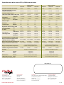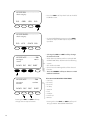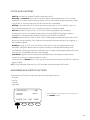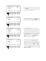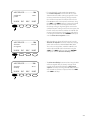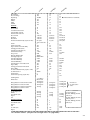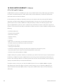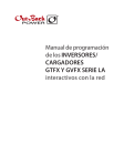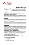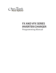
1
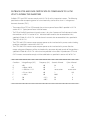
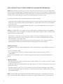
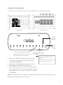
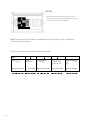
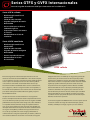
Series GTFX y GVFX Internacionales
Inversor/cargador de onda sinusoidal pura interactivo con la red eléctrica
••
Serie GTFX sellado
•Brinda energía cuando la red
eléctrica falla
• Salida de onda sinusoidal
• Cargador inteligente de baterías
• Hasta 23 kVA
•Carcasa sellada para condiciones
ambientales rigurosas
•
Componentes internos resistentes a
la corrosión
•Mantenimiento en el sitio de
instalación
Serie GVFX ventilada
•Brinda energía cuando la red
eléctrica falla
• Salida de onda sinusoidal
• Cargador de baterías inteligente
• Hasta 30 kVA
• Carcasa “a prueba de insectos”
•Mantenimiento en el sitio
de instalación
GVFX ventilado
GTFX sellado
El inversor/cargador de onda sinusoidal pura interactivo con la red
eléctrica de la serie Internacional de OutPower es una solución completa
a sus necesidades de energía. La serie Internacional ha sido diseñada para
su uso en países con 50 Hz que cuentan con redes eléctricas públicas
con tensiones de CA nominal de 230 VCA/50 Hz. Para las áreas que
frecuentemente sufren inestabilidad eléctrica tal como sobretensiones,
picos o apagones, o donde no se logra sincronizar con la red pública, se
han acortado los temporizadores de reconexión de la serie Internacional
para reducir el tiempo de inactividad del sistema global y mejorar la
funcionalidad del sistema.
Incorpora un inversor de onda sinusoidal de CC a CA, cargador de
baterías e interruptor de transferencia de CA incorporado dentro de una
carcasa de aluminio inyectado a presión; el inversor/cargador serie GTFX
y GVFX Internacional le permite vender energía solar, eólica o hidráulica
a la red pública mientras suministra energía de respaldo instantánea
en el caso de que se produzca un corte de energía de la red pública. El
interruptor de transferencia incorporado desconecta automáticamente
sus cargas de la red pública y suministra la energía desde el inversor
en caso de que se produzca un corte de energía, permitiéndole así
continuar usando su energía de respaldo solar y de baterías, a diferencia
de los sistemas tradicionales de conexión a la red eléctrica. El cargador
inteligente de baterías con multietapas de carga prolonga la vida útil
de sus baterías y las comunicaciones de red incorporadas permiten
comunicaciones simultáneas de hasta diez componentes de OutBack
Power dentro del sistema. La arquitectura exclusiva de sistema modular
significa que podrá incrementar la potencia de salida con tan sólo
incorporar un inversores/cargadores adicional. Nuestra serie GTFX
Internacional utiliza una carcasa sellada que puede trabajar bajo las
condiciones ambientales más rigurosas, tales como áreas con alto
nivel de humedad y aire marino corrosivo, mientras que la serie GVFX
Internacional utiliza una carcasa ventilada con orificios con pantalla
"a prueba de insectos" que permite alta potencia de salida de CA para
diferentes condiciones de operación.
Los inversores/cargadores de OutBack Power son la única opción cuando
necesita una solución de energía de onda sinusoidal pura, potente,
modular y confiable para su hogar, negocio o para usos extremos.
www.outbackpower.com
Especificaciones de las series GTFX y GVFX Internacionales
Modelos sellados
Modelos ventilados
GTFX2012E
GTFX2024E
GTFX2348E
GVFX2612E
GVFX3024E
GVFX3048E
Tensión de entrada de CC nominal
12 VCC
24 VCC
48 VCC
12 VCC
24 VCC
48 VCC
Capacidad nominal de potencia
continua a 25°C (77°F)
2000 VA
2000 VA
2300 VA
2600 VA
3000 VA
3000 VA
Tensión de CA/Frecuencia
230 VCA 50 Hz
230 VCA 50 Hz
230 VCA 50 Hz
230 VCA 50 Hz
230 VCA 50 Hz
230 VCA 50 Hz
Salida eficaz de CA continua a 25°C (77°F)
8.7 ACA
8.7 ACA
10.0 ACA
11.3 ACA
13.0 ACA
13.0 ACA
Completo
~ 20 vatios
~ 20 vatios
~ 20 vatios
~ 20 vatios
~ 20 vatios
~ 20 vatios
Modo
búsqueda
~ 6 vatios
~ 6 vatios
~ 6 vatios
~ 6 vatios
~ 6 vatios
~ 6 vatios
90%
92%
93%
90%
92%
93%
Típica
2%
2%
2%
2%
2%
2%
Máximo
5%
5%
5%
5%
5%
5%
±2%
±2%
±2%
±2%
±2%
±2%
Pico
28 ACA
35 ACA
35 ACA
28 ACA
35 ACA
35 ACA
RMS
20 ACA
25 ACA
25 ACA
20 ACA
25 ACA
25 ACA
Sobretensión
4600 VA
5750 VA
5750 VA
4600 VA
5750 VA
5750 VA
5 segundos
4000 VA
4800 VA
4800 VA
4000 VA
4800 VA
4800 VA
30 minutos
2500 VA
3100 VA
3100 VA
3100 VA
3300 VA
3300 VA
Corriente máxima de entrada de CA
30 ACA
30 ACA
30 ACA
30 ACA
30 ACA
30 ACA
Rango de tensión de entrada de CA
(ajustable através del MATE)
160 a 300 VCA
160 a 300 VCA
160 a 300 VCA
160 a 300 VCA
160 a 300 VCA
160 a 300 VCA
Rango de frecuencia de entrada de CA
44 a 56 Hz
44 a 56 Hz
44 a 56 Hz
44 a 56 Hz
44 a 56 Hz
44 a 56 Hz
Rango de tensión de entrada de CC
10.5 a 17 VCC
21 a 34 VCC
42 a 68 VCC
10.5 a 17 VCC
21 a 34 VCC
42 a 68 VCC
Consumo de
energía en reposo
Eficiencia típica
Distorsión
armónica total
Regulación de la tensión de salida
Corriente máxima
de salida
Capacidad de
sobrecarga de CA
0 a 50°C (capacidad de potencia
reducida con temp. superior a 25°C)
Rango de temperatura de operación
Salida de carga de batería continua
Garantía
Peso
Dimensiones
(Alto x Ancho x Largo)
100 ACC
55 ACC
35 ACC
0 a 50°C (capacidad de potencia
reducida con temp. superior a 25°C)
120 ACC
85 ACC
45 ACC
Estándar 2 años/Opcional 5 años
Estándar 2 años/Opcional 5 años
Unidad
29 kg (62 lbs)
28 kg (61 lbs)
Envío
31 kg (67 lbs)
28 kg (64 lbs)
33 x 21 x 41 cm (13 x 8.25 x 16.25”)
30 x 21 x 41 cm (12 x 8.25 x 16.25”)
55 x 33 x 56 cm (21.75 x 13 x 22”)
55 x 33 x 56 cm (21.75 x 13 x 22”)
Unidad
Envío
* Especificaciones sujetas a cambios sin previo aviso
Disponible en:
Corporate Office:
5917 195th St. NE
Arlington, WA 98223 USA
Phone: +1 360 435 6030
Fax: +1 360 435 6019
www.outbackpower.com
European Office:
Hansastrasse 8
D-91126
Schwabach, Germany
Phone: +49 9122 79889 0
Fax: +49 9122 79889 21
Asia Office:
Suite 1903, Tower 1, China Hong Kong City
33 Canton Road, Kowloon
Hong Kong
Phone: +852 2736 8663
Fax: +852 2199 7988
Latin American Office:
15105 Cedar Bluff Pl.
Wellington, FL 33414 USA
Phone: +1 561 792 9651
Fax: +1 561 792 7157
12/12
Grid-Interactive
GTFX AND GVFX
INVERTER/CHARGER
Programing Manual
Warranty Summary
Dear OutBack Customer,
Thank you for your purchase of OutBack products. We make every effort to assure our power
conversion products will give you long and reliable service for your renewable energy system.
As with any manufactured device, repairs might be needed due to damage, inappropriate use, or
unintentional defect. Please note the following guidelines regarding warranty service of OutBack
products:
• Any and all warranty repairs must conform to the terms of the warranty.
• All OutBack equipment must be installed according to their accompanying instructions and manuals
with specified over-current protection in order to maintain their warranties.
• The customer must return the component(s) to OutBack, securely packaged, properly addressed,
and shipping paid. We recommend insuring your package when shipping. Packages that are not
securely packaged can sustain additional damage not covered by the warranty or can void warranty
repairs.
• There is no allowance or reimbursement for an installer’s or user’s labor or travel time required to
disconnect, service, or reinstall the damaged component(s).
• OutBack will ship the repaired or replacement component(s) prepaid to addresses in the continental
United States, where applicable. Shipments outside the U.S. will be sent freight collect.
• In the event of a product malfunction, OutBack cannot bear any responsibility for consequential
losses, expenses, or damage to other components.
• Please read the full warranty at the end of this manual for more information.
About Outback Power Systems
OutBack Power Systems is a leader in advanced energy conversion technology. Our products include
true sine wave inverter/chargers, maximum power point charge controllers, system communication
components, as well as breaker panels, breakers, accessories, and assembled systems.
Notice of Copyright
FX Series Inverter/Charger Programming Manual © 2007 All rights reserved.
Disclaimer
UNLESS SPECIFICALLY AGREED TO IN WRITING, OUTBACK POWER SYSTEMS:
(a) MAKES NO WARRANTY AS TO THE ACCURACY, SUFFICIENCY OR SUITABILITY OF ANY TECHNICAL OR OTHER
INFORMATION PROVIDED IN ITS MANUALS OR OTHER DOCUMENTATION.
(b) ASSUMES NO RESPONSIBILITY OR LIABILITY FOR LOSS OR DAMAGE, WHETHER DIRECT, INDIRECT,
CONSEQUENTIAL OR INCIDENTAL, WHICH MIGHT ARISE OUT OF THE USE OF SUCH INFORMATION. THE USE OF
ANY SUCH INFORMATION WILL BE ENTIRELY AT THE USER’S RISK.
Contact Information:
OutBack Power Systems
19009 62nd Ave. NE
Arlington, WA 98223 Phone (360)435-6030 • Fax (360)435-6019
Date and Revision • September 2007 REV A
1
www.outbackpower.com
TABLE OF CONTENTS
Warranty Summary.................................................................................................................................................................................. 1
Certificate of Compliance.................................................................................................................................................................... 3
Welcome to the OutBack Power Systems FX Series Inverter/Charger System................................................... 4
Safety....................................................................................................................................................................................................... 4
FX Series Inverter/Charger Programming.................................................................................................................................. 5
Concerns............................................................................................................................................................................................... 5
Options................................................................................................................................................................................................... 5
Components and Connections........................................................................................................................................................ 6
Powering Up................................................................................................................................................................................................. 7
Stacking Options....................................................................................................................................................................................... 9
Classic Series....................................................................................................................................................................................... 9
Stacking And Assigning FX Status.................................................................................................................................................. 9
Master.................................................................................................................................................................................................... 9
Classic Slave......................................................................................................................................................................................... 9
Programming the FXs................................................................................................................................................................... 10-12
Master....................................................................................................................................................................................................13
Classic Slave.......................................................................................................................................................................................13
Power Save Levels...................................................................................................................................................................................14
AC ON ................................................................................................................................................................................................. 15-16
Auxiliary (AUX) Functions...................................................................................................................................................................17
List of AUX Functions...................................................................................................................................................................20
Adjustable AUX Output Functions......................................................................................................................................20
Battery Charging Instructions..........................................................................................................................................................23
Maintenance..............................................................................................................................................................................................23
FX Default Values.....................................................................................................................................................................................24
Warranty........................................................................................................................................................................................................25
Product Registration..............................................................................................................................................................................26
10-Year Limited Warranty (California).................................................................................................................................. 27-29
2
OutBack GTFX and GVFX Certificate of Compliance to UL1741
Utility-Interactive Inverters
OutBack GTFX and GVFX inverters comply with UL1741 for utility-interactive inverters. The following
specifications refer to exporting power to a simulated utility source of less than 1% voltage total
harmonic distortion (THD).
• The output of the GTFX or GVFX exceeds the minimum power factor of 0.85 specified in UL1741
section 45.2.2. Typical power factor is 0.96 or better.
• The THD of the RMS (root/means/square) current is less than 5 percent of the fundamental under
the conditions of UL1741 section 45.4.2. Individual odd harmonics do not exceed the limits
specified in Table 45.1 of UL1741. Individual even harmonics do not exceed the limits specified in
Table 45.2 of UL1741.
• The GTFX and GVFX inverters cease to export power to the simulated utility source under islanding
conditions specified in section 46.3 of UL1741.
• The GTFX and GVFX inverters cease to export power to the simulated utility source after the
output voltage and frequency of the simulated utility source are adjusted to each of the conditions
specified in Table 46.1 of UL1741 within the time specified in that table. All production GTFX and
GVFX inverters are tested to comply with the table below as specified in section 46.2 of UL1741.
Frequency (Hz)
Condition Voltage Range (VAC)
A <60
60
B <=60 to <105.6
60
C >=105.6 to <=132
60
D >132 to <164.4
60
E >=164.4
60
F 120
<59.3
G 120
>60.5
3
Seconds Allowed
Cycles Allowed
0.1
6
2
120
no cessation
no cessation
2
120
0.033
2
0.1
6
0.1
6
Welcome to the OutBack Power Systems FX Series
Inverter/Charger System
The FX Series Inverter/Charger offers a complete power conversion system—DC to AC, battery charging,
and an AC Transfer Switch—and can be used for stand-alone or back-up applications.
OutBack Power Systems does everything possible to assure the components you purchase will function
properly and safely when installed as instructed according to local and national electrical codes. Please
read all of the following instructions and the instructions that come with any OutBack components included in your power system. Further instructions on individual FX set-ups as well as systems assemblies are
included with the FX and VFX Series Inverter/Charger Installation Manual.
The OutBack Power Systems FX Series Inverter/Charger is ETL listed to UL1741 (Inverters, Converters, Controllers, and Interconnection System Equipment for Use with Distributed Energy Resources). All Mobile FX
Series Inverter/Chargers are ETL listed to UL 458
Grounding Instructions – Each FX should be connected to a grounded, permanent wiring system. For most
installations, the negative battery conductor should be bonded to the grounding system at one (and only
one) point in the DC system. All installations must comply with all national and local codes and ordinances.
System grounding as required by the National Electric Code, ANSI /NFPA 70-1996, is the responsibility of the
system installer.
The equipment ground is marked with this symbol:
The Grid-interactive FX and VFX Inverter/Charger Programming Manual covers safety and the programming or
“stacking” multiple FXs using the OutBack Power Systems MATE.
IMPORTANT SAFETY INSTRUCTIONS
General Precautions
1. Use caution whenever working around electricity, electrical components, and batteries. There is always a potential
for shocks, burns, injury, and even death if an installer or user comes in contact with electricity.
2. Read all instructions and cautionary markings on the FX, the batteries and all appropriate sections of this manual as
well as other component manuals before using the system.
3. Be sure each system FX is securely installed according to the FX and VFX Series Inverter/Charger Installation Manual.
4. Follow all local and national electrical codes when installing OutBack equipment and components.
Note:
• Neither the GTFX nor the GVFX is designed to be used with a generator. They are strictly for grid-interactive usage.
• An OutBack MATE is required to program the FXs beyond their default values.
• If an OutBack Charge Controller is in use, be sure to read its manual for optimum operation with a grid-interactive FX.
• When powered up, the GTFX/GVFX will automatically sense if a utility grid is present and then connect to it after a 30second delay. There is a five-minute delay before battery charging starts, which is done as a default action to assure
the batteries are charged should the grid fail. The inverter can sell power to the grid after the batteries are charged.
• Ul 1741 requires approved surge protection for a grid-interactive system. The optional OutBack FLEXware Surge
Protector meets this requirement.
4
Grid-INTERACTIVE FX Series Inverter/Charger Programming
Note: Please see the FX and VFX Series Inverter/Charger Installation Manual to install, wire, and connect
each FX Series Inverter/Charger. This programming manual assumes all FXs have been installed and are
ready to program according to the way they were wired. To familiarize yourself with the programming
concepts, please read through the entire manual before programming your system.
Up to two grid-interactive FXs can be combined and wired or “stacked.”
• Stacking FXs does not refer to physically placing one FX on top of another, but to how they are wired
within the system and then programmed for operation. Stacking allows all the FXs to work together
as a single system.
• Stacking assigns the FXs to power individual legs of the system and to operate at certain times; this
order is assigned using the MATE.
NOTE: An OutBack MATE with a code revision of 3.30 or higher is required to recognize and program
Grid-Interactive FXs. When multiple FXs are used, each needs to be assigned a status—Master or Slave
(at least one FX must be a Master).
• The Master FX is the primary and most heavily used unit. The loads and demands of the system
determine when and which Slaves are used. A Slave FX assists when the load demands are more
than the Master FX can handle alone.
• This is an orderly process as long as the user assigns each FX correctly. This is mainly a matter of
paying attention to the Port number for each FX when programming with the MATE.
Stacking Concerns
FXs should be wired and stacked appropriately to their individual power system. Problems can occur
when:
• An FX is incorrectly wired.
• An FX plugged into a HUB Port is mistakenly programmed (assigned the wrong status) or
misidentified.
An easy rule to remember is any FX wired to a specific phase or leg must be programmed to that
phase.
Stacking Options
• The Grid-Interactive FX Series Inverter/Chargers can be stacked in Classic Series only, which is limited
to two grid-interactive FXs.
• A HUB-4 or HUB-10 must be included to stack grid-interactive FXs. The Grid-Interactive FX cannot do
time-of-day selling.
• If the utility grid fails, the GTFX or GVFX seamlessly transfers the loads to the battery bank. When
the utility grid reappears, the Grid-Interactive FX automatically recharges the battery bank in case of
future power outages.
Note: The FW-X240 Auto Transformer cannot be used for stacking with a Grid-Interactive FX system.
The FW-X240 can be used to step-up the AC output of a single Grid-Interactive FX system, however.
5
Components and Connections:
1. With all AC and DC breakers OFF, connect all FXs to the HUB with individual lengths of CAT5 cable.
BYPASS
OUTPUT INPUT
AC Breakers Off
DC Breakers Off
POWER
HUB
2nd MATE
port is not
operable
10
9
8
7
6
5
4
Slave FXs plug into Ports 02 and higher
OutBack Charge Controllers plug into any
ports after the last FX is connected.
3
2
1
2ND
Mate
1st
Mate
MATE
connects
at 1st MATE
port
The FX connected to Port
01 is always programmed
as the Master.
a) Connect the OutBack MATE after all other components,
including any OutBack Charge Controllers, have been
connected and powered up.
b) Components installed after powering up the system will
require repolling the MATE (please see page 8).
c) With the MATE, a user assigns a status and stacking value to
the FX on each Port. These status and value assignments can
be changed at any time as long as the Master FX is plugged
into HUB Port 01.
•“Master” for one and two-phase
systems
• The Master FX is always considered to
be the leg one or L-1 phase.
Note: Pay attention to the Port number on the screen! Be sure the FX whose status and stacking value
you’re changing is the one you mean to change.
6
2. With the FXs connected to the HUB, turn only the DC breakers ON and power up the components. All AC
breakers should be OFF.
BYPASS
OUTPUT INPUT
AC Breakers Off
DC Breakers On
LED Color
LED Action
Green
LED Indicates
Solid GREEN
Flashing GREEN
Off
Inverter ON
Search Mode or Slave Power Yellow
Off
AC Source is Connecteced
AC Input Live-Waiting to Connect to the FX
No AC Input Present
Red
Solid RED
Flashing RED
Error-Error Message, dis-
plays on the MATE
Warning: Non-critical FX fault, the MATE can access this information
Solid YELLOW
Flashing YELLOW
Inverter OFF
Note: Powering up the FXs can cause the red ERROR
STATUS light to blink. After 5-10 seconds, the green
INVERTER light should be bright and the ERROR and
AC IN lights dark. The FX is now producing AC output
voltage.
7
3. After powering up the components, connect the MATE to the HUB.
a) Plug the MATE into the 1st MATE Port on the HUB.
b) The MATE will power up and should recognize any component connected to the HUB.
c) The MATE can then program the FXs.
d) The fifth MATE screen (“Port Assignment”) should display all the FXs and any Outback Charge Controllers in
the system.
MATE Screens
PATH
G’day Mate (C) 2004
OutBack Version
Searching
Port Assignment
Code a.aa
for Devices
1> FX 2> FX 3> CC 4> CC
Power Systems
Serial #xxxxxxxx
Screen EE b.bb
HUB Found
5>
6>
7>
9>
10>
2M>
8>
4. To verify the MATE recognizes each HUB connected FX and OutBack Charge Controller, disconnect and then
either (a) reconnect the MATE to view its boot-up and repoll sequence or (b) follow this path to manually repoll:
PATH
MAIN-------------------
SETUP-----------------
12.15:30p
SUM STATUS SETUP ADV
SETUP/MATE/PAGE1
SETUP/MATE/PAGE2
SETUP/MATE/COMM
mate code rev: 402
choose category:
choose produce:
choose device:
choose category:
FX
CLOCK CNT GLOW PG2
MATE
PG1 SUMRY COMM MAIN BACK REPOLL PC DEBUG
The FXs are now ready to be programmed according to the stacking options described in the next
section.
8
STACKING OPTIONS
OutBack Grid-Interactive FXs can be stacked in Classic Series only.
Classic Stacking
• Two FXs are wired to two 120 VAC output legs producing 240 VAC between them.
• Each FX powers one leg and acts independently of the other, but both combine when 240 VAC is
required for a load.
• The AC input must be 240 split phase VAC.
LOAD
3 kW
120 VAC
Leg 2
3 kW 120 VAC
or
3 kW
120 VAC
Leg 2
6 kW
240 VAC
Leg 1
and
Leg 2
3 kW 120 VAC
Stacking and Assigning FX Status
Stacking Phases/Assigning FX Status (in order as they appear on the MATE):
1. Master
2. Classic Slave
Use the MATE to establish the order or hierarchy of all the system FXs by designating one as the Master
and one as the Classic Slave.
1. Master
• This is the default ranking of every FX. It applies to one-phase and two-phase systems.
• One Master FX is established for every multiple FX system.
• Each Grid-Interactive FX can be a Master as long as each is connected to a separate AC output leg
(both HOT and NEUTRAL)
• If one Grid-Interactive FX is designated as the system’s only Master, it is always considered to be the
Leg 1 phase.
2. Classic Slave
• Classic Slave is the designation of the second FX in a two-inverter, split-phase system that produces
240 VAC without using an FW-X240 Auto Transformer.
• This FX is plugged into Port 02 of the HUB and is considered to be the L2 phase.
9
PROGRAMMING THE FXs
Once the MATE recognizes each FX (and OutBack Charge Controller), push and hold the first two soft
keys simultaneously to return to the MAIN menu. To program the FXs, go to the ADV/FX/STACK menu
on the MATE navigating with the following steps:
MAIN--------------------------
• Press the <ADV> soft key.
12:12:16A
SUM STATUS SETUP ADV
Note: Pressing and holding the first two soft keys
at the same time will always bring up the Main
Menu screen.
ADV/SETTINGS/WARNING
changes made could adversely affect
system performance
• Push any soft key on the ADV/SETTINGS/WARNING
screen and go to the ADV/PASSWORD screen.
ADV/PASSWORD
enter the password
• The screen displays <132>. Press the <INC> button
until it scrolls to the password 141.
132
ENTER INC
DEC
EXIT
ADV/PASSWORD
enter the password
• Push the <ENTER> soft key.
141
ENTER INC
DEC
EXIT
10
ADV
choose device:
FX
CC
• In the ADV menu, press the <FX> soft key.
DC
MATE
ADV/FX/PAGE 1---------------choose category:
ADV
INV
• On the ADV/FX/PAGE 1 screen, press the <PG2>
soft key and go to the ADV/FX/PAGE2 screen.
CHGR
PG2
ADV/FX/PG2------------------choose category:
PG1
GRID
• Press the <PG3> soft key which leads to the
ADV/FX/PAGE3 screen.
GEN
PG3
ADV/FX/PAGE3---------------choose category:
PG2
11
AUX
• On the ADV/FX/PAGE3 screen, press the
<STACK> soft key.
STACK PG4
ADV/FX/STACK--------P01
stack
phase
DOWN INC
Master
DEC PORT
• Stacking the FX Inverter/Chargers begins on this
screen. See specific stacking procedures in the next
section.
ADV/FX/STACK----------P01
• Port 01 always takes the Master FX.
DOWN INC
• Pressing the <PORT> soft key changes the HUB
Port whose value you wish to adjust.
stack
phase
Master
DEC
PORT
Pressing the <INC> or <DEC> soft keys
changes the stacking phase.
12
Master
With the Port 01 FX as the Master, press the <PORT> soft key to change the remaining Ports and
designate the remaining FXs as Slaves. The MATE screen for Port 02 will look like this:
ADV/FX/STACK--------P02
stack
phase
DOWN
Master
INC DEC PORT
ADV/FX/STACK---------P02
stack
phase
DOWN
Master
INC DEC PORT
• The MATE is now ready to program the FX plugged
into Port 02 of the HUB.
• Master is the factory default value for each grid-interactive FX.
• Pressing the <INC> soft key will keep the MATE’s
attention on Port 02, but will change the stack phase
to Classic Slave screen. Port 02 will then be assigned
as a Classic slave. You can change the stacking phase
by pressing the <INC> or <DEC> soft keys and
change to a different port by continuously pushing
the <PORT> soft key.
Note: There are no <OK> or <DONE> commands in the stacking menu. Whichever value—Master or
Slave—shows up on the MATE screen will be assigned to the chosen Port (and FX) upon leaving that
screen. It’s important to watch the Port number in the top right corner of each screen to be sure you’ve
assigned it the desired status.
CLASSIC Slave
ADV/FX/STACK---------P02
stack
phase
Classic
DOWN INC DEC
13
Slave
• PO2 is now assigned as a Classic Slave.
PORT
Power Save Levels
Depending on the model, each FX consumes 20-25 watts of power when it remains on, even if it isn’t
actively inverting or charging. OutBack offers a power save feature for its non-grid-interactive systems,
but is not available for grid-interactive systems. The power save level screens can be viewed from any
stacking screen, but the default values should remain unchanged in a grid-interactive system.
ADV/FX/STACK------------P01
(ANY SCREEN IN STACK PHASE)
DOWN INC DEC
• Press the <DOWN> soft key once to view the power
save level master adjust only screen
PORT
ADV/FX/STACK-----------P01
power save level
master adjust only
DOWN INC DEC
• Press the <DOWN> soft key to view the power save
level slave adjust only screen.
PORT
ADV/FX/STACK---------P02
power save level
slave adjust only
1
DOWN INC DEC
PORT
• Do not adust these values when using a gridinteractive FX.
14
AC ON
• With the programming completed, turn the AC
output breakers ON with the AC BYPASS on the AC
breaker panel switched to NORMAL.
BYPASS
OUTPUT INPUT
Note: If you are using the FW-X240 Auto Transformer for step-up functioning, turn on its breaker now.
Otherwise, go to the next step.
Verify the AC voltage output through the MATE following path:
PATH
15
MAIN-------
SETUP------------ STATUS/FX/PAGE1---------- Float
P00
12.15:30p
choose device:
choose category:
inv 0.0Kw zer 0.0kw
chg 0.0kw buy 0.0kw
STATUS/FX/METER--P00
output
117 vac
voltage
SUM STATUS SETUP ADV FX CC DC MAIN MODES METER BATT PG2 DOWN STATUS PORT
DOWN UP TOP PORT
• Turn the AC input breakers ON.
BYPASS
OUTPUT INPUT
If the FX’s AC source is available, the yellow AC IN
STATUS light will blink. The FX will connect to the
utility grid when the voltage is within 108-140 VAC and
the frequency between 59.3-60.5 Hz. After about 30
seconds, the AC IN light should stop blinking and stay
lit. A five-minute waiting period begins before selling
or charging can occur. The FX can then perform a
battery charge using the available AC.
16
Auxiliary (AUX) Functions
The AUX output provides a 12 VDC, 0.7 ADC max output at the AUX terminals to control either DC or
AC external loads. Typical loads include sending a fault alarm signal or running a small fan to cool the
FX.
MAIN-------------------------12:12:16A
SUM
STATUS SETUP
ADV
• Press the <ADV> soft key.
Note: Pressing and holding the first two soft keys at the
same time will always bring up the Main Menu screen.
ADV/SETTINGS/WARNING
changes made could
adversely affect
system performance
17
• Push any soft key on the ADV/SETTINGS/WARNING
screen and go to the ADV/PASSWORD screen.
ADV/PASSWORD-------------enter the password
132
ENTER INC
• The screen displays <132>. Press the <INC> button
until it scrolls to the password 141.
DEC
EXIT
ADV/PASSWORD---------------enter the password
• Push the <ENTER> soft key.
141
ENTER INC
DEC
EXIT
ADV-----------------------------choose device:
FX
CC
• In the ADV menu, press the <FX> soft key.
DC MATE
ADV/FX/PAGE 1---------------choose category:
ADV
INV
• On the ADV/FX/PAGE 1 screen, press the <PG2>
soft key and go to the ADV/FX/PAGE2 screen.
CHGR
PG2
18
ADV/FX/PG2--------------------choose category:
PG1
GRID
• Press the <PG3> soft key which leads to the ADV/
FX/PAGE3 screen.
GEN
PG3
ADV/FX/PAGE3----------------choose category:
PG2
AUX
STACK PG4
ADV/FX/AUX---------------P00
aux output
control
DOWN INC
AUTO
DEC PORT
ADV/FX/AUX--------------P00
aux output
function
DOWN INC
Cool Fan
DEC
PORT
Pressing the <INC> or <DEC> soft keys
changes the aux output function.
19
• On the ADV/FX/PAGE3 screen, press the <AUX>
soft key to adjust the AUX output set points and
operation.
• Selecting the <INC> or <DEC> soft keys changes
the mode of the AUX.
• AUTO allows the AUX to perform a selected AUX
OUTPUT FUNCTION, determined in the following
screens.
• OFF disables the AUX.
• ON activates the AUX regardless of the selected
function.
• Press the <DOWN> soft key to select on an AUX
OUTPUT FUNCTION
There are nine AUX OUTPUT FUNCTIONS:
• Cool Fan
• Divert DC
• Divert AC
• AC Drop
• Vent Fan
• Fault
• GenAlert
• Load Shed
• Remote
Pressing either the <INC> or <DEC> soft key will
bring up another AUX OUTPUT FUNCTION
LIST OF AUX FUNCTIONS
• Cool Fan activates the standard TurboFan which cools the FX.
• Divert DC and Divert AC allows the AUX to divert excess renewable energy to a DC or AC load,
respectively. This allows control of energy sources such as wind turbines or hydro-generators. When
using Divert AC, the AUX output will shut off if the inverter is overloaded.
• AC Drop is activated when an AC power source disconnects from an FX. An indicator, such as an
alarm, connected to the AUX warns a user that AC power is no longer available.
• Vent Fan provides 0.7 amps to run a 12 VDC fan for removing hydrogen from the battery
compartment. Vent Fan can operate automatically when the VENTFAN ON voltage set point is
exceeded or it can operate intermittently by adjusting the VENTFAN OFF PERIOD.
• In Fault mode, the AUX can send an alarm signal via radio, pager, or telephone device when the FX
enters into an error condition. Fault mode can also be used to log error conditions by triggering an
event recording device.
• GenAlert, through a 12VDC relay, will tell the system to start a two-wire type generator when
the battery voltage falls below a certain set point. GenAlert can be adjusted according to the
shortfallbattery voltage, the amount of time spent at this voltage, the recharged voltage and amount
of time at this voltage before GenAlert is de-energized.
• Load Shed energizes the AUX the reduce the load demand on the batteries and the inverter
function, thus acting as a load management system.
• Setting the AUX to Remote allows a message sent through the serial port on the MATE to switch the
AUX on and off.
Note: Using Advanced Generator Start (AGS) overrides any programmed AUX function.
Adjustable AUX OUTPUT FUNCTIONS
There are four AUX functions whose settings can be adjusted by the user:
• Diversion
• Vent Fan
• GenAlert
• Load Shed
ADV/FX/AUX-------------P00
aux output
function
DOWN INC
Remote
• From the Remote aux output function screen, press
the <DOWN> soft key
DEC
PORT
20
ADV/FX/AUX-------------P00
aux output
function
DOWN INC
Remote
DEC
PORT
ADV/FX/AUX---------------P00
genalert
on setpoint
DOWN INC
11.5vdc
DEC
DOWN INC
11.0 vdc
DEC
PORT
ADV/FX/AUX---------------P00
ventfan
on setpoint
DOWN INC
21
13.0 vdc
DEC
• The genalert on setpoint functions are not available
for grid-interactive FXs. Press the <DOWN> soft key
three times to view the loadshed off setpoint screen.
PORT
ADV/FX/AUX---------------P00
loadshed
off setpoint
• From the Remote aux output function screen, press
the <DOWN> soft key. This will bring up the first of
several screen used to adjust which ever mode you
have chosen for the AUX function.
PORT
• The loadshed off setpoint is the battery voltage
which triggers the AUX to reduce the inverter and
battery loads. When the battery voltage drops below
this value for three seconds, the AUX powers a DC
coil relay to disconnect an AC load. Once triggered,
loadshed remains on for at least three minutes. The
loadshed off setpoint is adjustable from10 VDC-14
VDC in 0.1 VDC increments using the <INC> and
<DEC> soft keys. Press the <DOWN> soft key to
bring up the ventfan on setpoint.
• When the AUX is set to ventfan, a fan ventilates
a battery enclosure. The ventfan on setpoint
establishes the battery voltage which energizes the
AUX and thus the fan for a one minute period. The
voltage setting has a range of 10.0 VDC-16.0 VDC in
0.1 VDC increments using the <INC> and <DEC>
soft keys. Recharging causes batteries to emit mostly
hydrogen gas; higher recharging voltages emit more
gas. Press the <DOWN> soft key to view the ventfan
off period screen.
ADV/FX/AUX---------------P00
ventfan off
period
DOWN INC
5 min
DEC
PORT
ADV/FX/AUX---------------P00
diversion
on setpoint
DOWN INC
14.6 vdc
DEC
PORT
ADV/FX/AUX--------------P00
diversion
off delay
DOWN INC
30 sec
DEC
PORT
• If a ventilation fan is only needed intermittently,
the ventfan off period shuts the fan off for a userdetermined time before starting up again for a oneminute period when the battery voltage exceeds
the ventfan on setpoint. This off period can be set
from 0-30 minutes in one-minute increments using
the <INC> and <DEC> soft keys. Setting this period
to zero will keep the fan running the entire time
the battery voltage is high enough to activate the
ventfan function. Setting it to five minutes means the
fan will run for one minute and then shut off for five
minutes until the battery voltage drops and the fan
is no longer needed. Press the <DOWN> soft key to
view the diversion on setpoint screen.
• After deciding on Divert DC or Divert AC, use the
diversion on setpoint screen to choose the voltage
which will activate this AUX OUTPUT FUNCTION.
This value can range from 12.0 VDC-16.0 VDC and
can be adjusted in 0.1 VDC increments using the
<INC> and <DEC> soft keys. Press the <DOWN>
soft key to view the diversion off delay screen.
• The diversion off relay determines how long the AUX
will be energized after the battery voltage which
caused the diversion falls below the diversion on
setpoint. This delay can range from 0-240 seconds in
one-second increments as adjusted with the <INC>
and <DEC> soft keys.
22
BATTERY CHARGING INSTRUCTIONS
Keeping your battery bank energized is very important. Although a battery bank can last for many
years if properly cared for, it can also be ruined in a short period of time if neglected.
Battery Charging Setpoints
To preserve your batteries always follow your battery manufacturer’s recommendations using the
following information:
•
•
•
•
Absorb Voltage
Float Voltage
Equalize Voltage
Recommended Depth of Discharge (DOD) of the batteries
These Absorb, Float, and Equalize voltage set points should be programmed into the FX through the
MATE (see MATE User Manual).
Maintenance
Please contact OutBack Power Systems Technical Services for any FX repairs due to malfunctions or
damage. For routine, user-approved maintenance:
• Disconnect all circuit breakers and related electrical connections before doing any cleaning or
adjustments.
• Solar modules may produce hazardous voltages when exposed to light; cover them with opaque
material before servicing any connected equipment.
• If a remote start system is used, disable the automatic starting circuit while servicing it to prevent
starting while servicing.
23
m
te
ys
Cs
VD
12
Float Voltage
Absorb Voltage
EQ Voltage
ReFloat
LBCO
LBCI
Sell RE
GenAlert
Off Set Point
On Set Point
Load Shed off Set Point
Vent Fan ON set Point
Diversion On Set Point
Absorb Time
EQ Time
Float Time
AC2/Gen Transfer Delay (Cycles for AC)
Search
Grid Lower Limit
Export Grid Lower Limit Only
Grid Upper Limit (USA)
Grid Upper Limit (Export)
Grid Connect Delay
Drop or Use
Charger Off/Auto/On
Aux Output Option
Gen Alert On Delay
Gen Alert Off Delay
Vent Fan Off Delay
Gen Window Lower Limit 60 Hz
Export Only
Gen Upper Window Limit 60 Hz
Export Only
Ac 1/Grid Transfer Delay (Cycles of AC)
Set AUX Control
Search Pulses
Search Pulse Spacing (Cycles AC)
Stacking Phase
InPut Select
Charge Rates for Vented 24 & 48 VDC
Charge Rates for Vented 12 VDC
Charge Rates for Sealed 24 & 48 VDC
Charge Rates for Sealed 12 VDC
Grid Input Settings
Set AC Input Size
Mobile
Non-Mobile (US)
Export
GT
Gen Input Settings
Mobile
Non-Mobile (US)
Export
GT
Set VAC (US)
Export
LT
AU
F
E
D
M
UM
M
MU
I
IN
XIM
MA
13.6
14.4
14.4 u
12.5
10.5
12.5
13.0
12
13
14
11
9
10
10
15
16
17 u(24VDC Grid-Tie is 29.2 default)
13
12
14
15
14
11
11
13
14.6
1.0 hours
1.0 hours
1.0 hours
60 cycles*
*20 for Grid-Tie
6
108
208
140
270
.5 min
USE
AUTO
COOL FAN
4 min
9 min
5 min
108
208
140
270
6
AUTO
8
60
12
10
10
10
12
0.0 hours
0.0 hours
0.0 hours
0 cycles
18V
14V
14V
16V
16V
24.0 hours
24.0 hours
24.0 hours
240 cycles
0
40
80
130
250
.2 MIN
N/A
50
115
220
150
300
15.0 min
N/A
0 min
0 min
0 min
40
80
130
250
0
240 min
240 min
30 min
115
220
150v
300
240
2
4
20
120
1 or 2 Phase
Master Gen
18 Amp AC
12 Amp AC
10 Amp AC
10 Amp
28 Amp
48 Amp
28 Amp
50 Amp
28
48
28
50
120
230
0 Amp AC
0 Amp AC
0 Amp AC
0 AMp AC
5 Amp
5 AMp
5 Amp
2
2
2
110
210
20 Amp AC
14 Amp AC
14 Amp AC
12 Amp AC
30 Amp
60 Amp
30 Amp
30
60
30
E models are
one-half of these
values
Correction Factor
24 VDC: Multiply 12VDC
values by 2
32 VDC: Multiply 12 VDC
values by 2.64
48 VDC: Multiply 12VDC
values by 4
125V
240V
FX Default Values (subject to change with FX upgrades)
24
WARRANTY
OutBack Power Systems Two Year Limited Warranty
OutBack Power Systems Inc. warrants that the products it manufactures will be free from defects in
materials and workmanship for a period of two (2) years subject to the conditions set forth below.
The limited warranty is extended to the original user and is transferable. The limited warranty term begins
on the date of invoice to the original user of the product. The limited warranty does not apply to any
product or part thereof damaged by a) alteration or disassembly, b) accident or abuse, c) corrosion, d)
lightning, e) reverse polarity, f ) repair or service provided by an unauthorized repair facility, g) operation
or installation contrary to instructions pertaining to the product.
OutBack Power Systems’ liability for any defective product or any part thereof shall be limited to the repair
or replacement of the product, at OutBack Power Systems’ discretion. OutBack Power Systems does not
warrant or guarantee the workmanship performed by any person or firm installing its products.
THIS LIMITED WARRANTY GIVES YOU SPECIFIC LEGAL RIGHTS, AND YOU MAY ALSO HAVE OTHER
RIGHTS THAT VARY FROM STATE TO STATE (OR JURISDICTION TO JURISDICTION). OUTBACK POWER
SYSTEMS’ RESPONSIBILITY FOR MALFUNCTIONS AND DEFECTS IN HARDWARE IS LIMITED TO REPAIR
AND REPLACEMENT AS SET FORTH IN THIS LIMITED WARRANTY STATEMENT. ALL EXPRESS AND IMPLIED
WARRANTIES FOR THE PRODUCT, INCLUDING BUT NOT LIMITED TO ANY IMPLIED WARRANTIES OF
AND CONDITIONS OF MERCHANTABILITY AND FITNESS FOR A PARTICULAR PURPOSE, ARE LIMITED IN
DURATION TO THE LIMITED WARRANTY PERIOD SET FORTH ABOVE AND NO WARRANTIES, WHETHER
EXPRESS OR IMPLIED, WILL APPLY AFTER SUCH PERIOD. SOME STATES (OR JURISDICTIONS) DO NOT
ALLOW LIMITATIONS ON HOW LONG AN IMPLIED WARRANTY LASTS, SO THE ABOVE LIMITATION MAY
NOT APPLY TO YOU.
OUTBACK POWER SYSTEMS DOES NOT ACCEPT LIABILITY BEYOND THE REMEDIES SET FORTH IN THIS
LIMITED WARRANTY STATEMENT OR LIABILITY FOR INCIDENTAL OR CONSEQUENTIAL DAMAGES,
INCLUDING WITHOUT LIMITATION ANY LIABILITY FOR PRODUCTS NOT BEING AVAILABLE FOR USE.
SOME STATES (OR JURISDICTIONS) DO NOT ALLOW THE EXCLUSION OR LIMITATION OF INCIDENTAL OR
CONSEQUENTIAL DAMAGES, SO THE ABOVE EXCLUSION OR LIMITATION MAY NOT APPLY TO YOU.
During the two year period beginning on the invoice date, OutBack Power Systems will repair or replace
products covered under this limited warranty that are returned to OutBack Power Systems’ facility or to
an OutBack Power Systems authorized repair facility, or that are repaired on site by an OutBack Power
Systems authorized repair technician. To request limited warranty service, you must contact OutBack
Power Systems at 360-435-6030 within the limited warranty period. If limited warranty service is required,
OutBack Power Systems will issue a Return Material Authorization (RMA) Number. Mark the outside of
the package with the RMA number and include a copy of the purchase invoice in the package. You
must ship the products back to OutBack Power Systems in their original or equivalent packaging,
prepay shipping charges, and insure the shipment or accept the risk of loss or damage during shipment.
OutBack Power Systems will ship the repaired or replacement products to you freight prepaid if you
use an address in the continental United States, where applicable. Shipments to other locations will be
made freight collect.
25
PRODUCT REGISTRATION
Your purchase of an OutBack Power Systems product is an important investment. Registering your
products will help us maintain the standard of excellence you expect from us in terms of performance,
quality and reliability.
Please take a moment to register and provide us with some important information.
NAME: __________________________________
E-MAIL: _ _______________________________
ADDRESS: _______________________________
SOLD BY: _______________________________
CITY:____________________________________
INSTALLER: _ ____________________________
STATE:________________ZIP CODE: __________
PURCHASE DATE: _ _______________________
COUNTRY: _______________________________
MODEL NUMBER:_________________________
TELEPHONE NUMBER: ______________________
__
SERIAL NUMBER: _________________________
Circle all that apply:
Off-Grid Installation Residential Installation
North America Location
Utility Connected Installation
Commercial Installation
Other ________________
Extended Warranty Application (U.S. and Canada only)
OutBack Power Systems offers an optional three year extension to the standard two year limited
warranty. Purchase of extended warranty coverage is available on products listed below provided
conditions shown are met. Extended warranty coverage must be purchased within 90 days of the
original sale of the product covered.
PRODUCT COST
Any FX Series Inverter/Charger
OutBack Charge Controller
MATE
HUB 4
HUB 10
Product Covered
REQUIRED SURGE PROTECTION
AC Input; AC Output, DC Input
DC Input; DC Output
NA
NA
NA
Serial Number
Quantity
EXTENDED WARRANTY
$300.00
$100.00
$50.00
$35.00
$50.00
Extended Warranty Cost
________________________ _________________________________ _______________
_____________________
________________________ _________________________________ _______________
_____________________
________________________ _________________________________ _______________
_____________________
________________________ _________________________________ _______________
____________________
Total _______________
Send check or money order payable to OutBack Power Systems. Washington residents please include
8.5% sales tax. Include a completed copy of this application and send to:
OutBack Power Systems
Extended Warranty Program
19009 62nd Ave NE • Arlington, WA 98223 USA
26
10-Year Limited Warranty (California)
GTFX, GVFX and PS1 Products
OutBack Power Systems, Inc. (“OutBack”) provides a ten-year (10) limited warranty (“Warranty”) against defects
in materials and workmanship for its GTFX, GVFX and PS1 products (“Products”) if installed in fixed location
applications within the State of California.
For this Warranty to be effective, the Product purchaser must complete and submit the applicable Product
registration card within ninety (90) days of the eligible Product’s first retail sale. The term of this Warranty is
governed by the date issued by OutBack on the 10-year Warranty Certificate. This Warranty applies to the
original OutBack Product purchaser, and is transferable only if the Product remains installed in the original use
location. The warranty does not apply to any Product or Product part that has been modified or damaged by the
following:
• Installation or Removal;
• Alteration or Disassembly;
• Normal Wear and Tear;
• Accident or Abuse;
• Corrosion;
• Lightning;
• Repair or service provided by an unauthorized repair facility;
• Operation contrary to manufacturer product instructions;
• Fire, Floods or Acts of God;
• Shipping or Transportation;
• Incidental or consequential damage caused by other components of the power system;
• Any product whose serial number has been altered, defaced or removed; or
• Any other event not foreseeable by OutBack.
OutBack’s liability for any defective Product, or any Product part, shall be limited to the repair or replacement of
the Product, at OutBack’s discretion. OutBack does not warrant or guarantee workmanship performed by any
person or firm installing its Products. This Warranty does not cover the costs of installation, removal, shipping
(except as described below), or reinstallation of Products.
To request warranty service, you must contact OutBack Technical Services at (360) 435-6030 or support@
outbackpower.com within the effective warranty period. If warranty service is required, OutBack will issue
a Return Material Authorization (RMA) number. A request for an RMA number requires all of the following
information:
27
Revision.2007-06-01
1. Proof-of-purchase in the form of a copy of the original Product purchase invoice or receipt confirming the
Product model number and serial number;
2. OutBack issued 10-year warranty certificate;
3. Description of the problem; and
4. Shipping address for the repaired or replacement equipment.
After receiving the RMA number, pack the Product(s) authorized for return, along with a copy of the original
purchase invoice and warranty certificate, in the original Product shipping container(s) or packaging providing
equivalent protection and mark the outside clearly with the RMA number. The sender must prepay all shipping
charges, and insure the shipment, or accept the risk of loss or damage during shipment. OutBack is not
responsible for shipping damage caused by improperly packaged Products, the repairs this damage might
require, or the costs of these repairs. If, upon receipt of the Product, OutBack determines the Product is defective
and that the defect is covered under the terms of this Warranty, OutBack will then and only then ship a repaired
or replacement Product to the purchaser freight prepaid, non-expedited, using a carrier of OutBack’s choice
within the continental United States, where applicable.
Shipments to other locations will be made freight collect. The warranty period of any repaired or
replacement Product is twelve (12) months from the date of shipment from OutBack, or the remainder
of the initial warranty term, which ever is greater.
THIS LIMITED WARRANTY IS THE EXCLUSIVE WARRANTY APPLICABLE TO OUTBACK PRODUCTS.
OUTBACK EXPRESSLY DISCLAIMS ANY OTHER EXPRESS OR IMPLIED WARRANTIES OF ITS PRODUCTS,
INCLUDING BUT NOT LIMITED TO ANY IMPLIED WARRANTIES OF MERCHANTABILITY OR FITNESS FOR A
PARTICULAR PURPOSE. OUTBACK ALSO EXPRESSLY LIMITS ITS LIABILITY IN THE EVENT OF A PRODUCT
DEFECT TO REPAIR OR REPLACEMENT IN ACCORDANCE WITH THE TERMS OF THIS LIMITED WARRANTY
AND EXCLUDES ALL LIABILITY FOR INCIDENTAL OR CONSEQUENTIAL DAMAGES, INCLUDING
WITHOUT LIMITATION ANY LIABILITY FOR PRODUCTS NOT BEING AVAILABLE FOR USE OR LOST
REVENUES OR PROFITS, EVEN IF IT IS MADE AWARE OF SUCH POTENTIAL DAMAGES. SOME STATES (OR
JURISDICTIONS) MAY NOT ALLOW THE EXCLUSION OR LIMITATION OF WARRANTIES OR DAMAGES, SO
THE ABOVE EXCLUSIONS OR LIMITATIONS MAY NOT APPLY TO YOU.
Revision.2007-06-01
28
10-Year Warranty Registration - California
To request a 10-year Limited Warranty; complete this form along
with a check or money order in the amount of $599 USD payable
to OutBack Power Systems, Inc., and return it to:
Outback Power Systems Inc.
19009 62nd Ave. NE • Arlington, WA 98223
NOTE: A 10-Year Limited Warranty Certificate will only be issued if this registration card is received by
Outback within 90 days of the date of the first retail sale of the eligible product. Please submit a copy
(not the original) of the product purchase invoice, which confirms the date and location of purchase, the
price paid, and the product model and serial number. The warranty certificate is available only for and
will only be issued for GTFX, GVFX and PS1 products installed in fixed location (non-mobile) applications
within the state of California.
10-Year Warranty Registration for GVFX, GTFX and PS1-California
System Owner
Name: ______________________________________
E-mail: __________________________________
Address: ____________________________________
City, State, Zip Code: _______________________
Country: ____________________________________
Telephone number: ________________________
Product
Product model number:________________________
Product serial number:______________________
Sold by:______________________________________
Purchase date: _____________________________
Please circle the three most important factors affecting your purchase decision:
• Price
• Product Reputation
• Reputation of OutBack Power
• Product Features
• Value
System
System install/commission date: __________________
System array size: __________________________
System array nominal voltage: ___________________
Type of PV modules: _______________________
System battery bank bize (amp hours):_____________
Type of batteries:___________________________
Please list other sources of back-up power:_____________________________________________________________
_____________________________________________________________________________
______________________________________________________________________________________
Installer
Installer: ____________________________________
Installer e-mail:____________________________
Installer address: ______________________________
Installer City, State, Zip: _____________________
Contractor number:____________________________
29
Revision.2007-06-26
30
European Sales Office
Barcelona, ESPAÑA
(+34) 600.843.845
19009 62nd Avenue NE
Arlington, WA 98223 USA
(+1) 360.435.6030
www.outbackpower.com
900-0087-01-00 REV A