1
SRI-500
User’s Manual
Rev. 1.5
October 3, 2010
Acuity Technologies
3475 Edison Way Bldg P
Menlo Park CA 94025
www.acuitytx.com
Page 1 of 20
TABLE OF CONTENTS
1.
OVERVIEW .......................................................................................................................................................3
1.1
1.2
1.3
2.
HARDWARE POWER UP ...............................................................................................................................4
2.1
3.
SCANNING OPERATION ................................................................................................................................3
USE AND MAINTENANCE .............................................................................................................................3
AZIMUTH MOTOR PATH PLANNING .............................................................................................................3
POWER/SIGNAL CONNECTION .....................................................................................................................4
SOFTWARE INSTALLATION .......................................................................................................................4
3.1
CD DIRECTORY STRUCTURE .......................................................................................................................4
3.1.1
Ethernet Connectivity ............................................................................................................................4
3.2
SOFTWARE INSTALLATION UNDER XP.........................................................................................................5
3.3
SOFTWARE INSTALLATION UNDER LINUX ...................................................................................................5
4.
PROGRAMMING INTERFACE.....................................................................................................................5
4.1
OVERVIEW ..................................................................................................................................................5
4.2
STATUS RETURN VALUES............................................................................................................................5
4.3
COMMUNICATION LINK COMMANDS ...........................................................................................................6
4.3.1
OpenScanner ................................................................................................................................6
4.3.2
CloseScanner..............................................................................................................................6
4.4
SCANNING LOCATION AND SPEED COMMANDS ...........................................................................................7
4.4.1
azimuthSpeed..............................................................................................................................7
4.4.2
elevationSpeed .........................................................................................................................7
4.4.3
azimuthPosition.......................................................................................................................7
4.5
MODE COMMANDS ......................................................................................................................................8
4.5.1
scanOnCommand ...........................................................................................................................8
4.5.2
scanOnSoftwareTrigger ........................................................................................................8
4.5.3
scannerTrigger .........................................................................................................................8
4.5.4
scanOnHardwareTrigger ........................................................................................................8
4.5.5
scannerSleep..............................................................................................................................9
4.5.6
scannerWake ................................................................................................................................9
4.6
SCAN AND TURRET MOTION COMMANDS .................................................................................................10
4.6.1
singleScan, repeatingScan.............................................................................................10
4.6.2
haltScan .....................................................................................................................................11
4.7
SCAN DATA ACQUISITION AND PROCESSING .............................................................................................12
4.7.1
createSRIpacketBuffer ......................................................................................................12
4.7.2
deleteSRIpacketBuffer ......................................................................................................12
4.7.3
receiveImagePacket..............................................................................................................13
4.7.4
createSRIImageBuffer.........................................................................................................14
4.7.5
deleteSRIImageBuffer.........................................................................................................15
4.7.6
addPacketToImage ..................................................................................................................15
4.8
DEMONSTRATION CLIENT SOFTWARE .......................................................................................................16
4.9
SRI-500 DATA SHEET, FOLLOWING PAGES.................................................................................................16
Page 2 of 20
1. Overview
The SRI-500 Scanning Rangefinding Imager consists of a pulse laser rangefinder, a turret mounted
scanning mirror, and a processor with Ethernet for SRI to client communications. The SRI-500 operates
by measuring the time difference between a transmitted laser pulse and a received laser pulse and
deflecting a high-speed mirror in azimuth and elevation to scan a field up to 130 by 600 degrees.
1.1 Scanning Operation
The SRI-500 acts as a scan data server for a client machine which communicates through a set of
commands transmitted via Ethernet. A scan is 1 to 30001 vertical lines of rangefinding data. Each vertical
line in a scan consists of 1 to 3001 range measurement points. The SRI-500 acquires and transmits scan
data in response to scanning commands transmitted to it from the client. Vertical lines are actually
slightly sloped, depending on the horizontal and vertical scan speeds set by the client. The maximum
vertical scan rate is 500 lines per second.
Scan data comes from the SRI-500 in a UDP packet defined by ScanDataPacket. Each 3D Range data
sample is defined by a 16 bit range value, two 16 bit angular direction values, and 1 byte value for signal
strength. This can then be converted to Cartesian coordinates by client side software included with the
scanner.
1.2 Use and Maintenance
The SRI-500 is a rugged system designed for use on mobile platforms. However, it should be protected
from severe shock and vibration, such as that which might be experienced on a vehicle without
suspension or with high engine vibration. In these cases the scanner should be mounted with grommets.
The motors for the turret and scanning mirror are brushless DC motors which will not generally need
maintenance over the life of the scanner.
The scanner is filled with dry nitrogen and sealed to prevent condensation and corrosion. Do not open the
scanner or break any seals. Doing so will void the warranty and necessitate repair.
The front window is filter glass, and should be kept clean ad free of scratches and dirt.
1.3 Azimuth Motor Path Planning
The turret of the SRI-500 moves through scans at nearly constant speeds. To accomplish this, the
SRI-500 performs intelligent path planning which moves the azimuth motor into the correct
position and speed for the next scan. For this to operate efficiently, it is recommended that the
repeating scan command be used, or that commands be queued so that the next scan may be
anticipated by the path planning algorithm. A turret positioning command is also available to
preposition the turret for quick scan response.
Page 3 of 20
2. Hardware Power Up
2.1 Power/Signal Connection
The SRI-500 requires 11 to 18 Volts and is designed to draw from an automotive or similar power
system. The supply must be capable of up to 50 amps burst (0.1 sec) and 15 amps continuous. 24/28V
systems are also available. Wire the power supply to the connector cables and plug in the connector with
the power switch off, then turn on the system.
An input trigger signal, logic high, is available on the input connector. External triggering of a preloaded scanning instruction sequence allows precise synchronization with external events. If not used, this
input should be left unconnected.
On power up the turret will seek center and stop with the optical axis aligned with one edge of the scanner
◦
housing. The turret window is not aligned with the optical axis, so the window will be at a 10 angle to the
housing.
Connect the SRI-500 ethernet jack to a hub, router, or access point with a CAT-5 Ethernet cable or to a
client machine with a crossover cable.
Pin A: Power.
Pin B: Ground.
Pin C: Scan Trigger Input.
Pin D: Scan Trigger Return.
If the Scan Trigger Input is used, this line must be connected to logic ground
in the signaling device.
3. Software Installation
3.1 CD Directory Structure
The SRI-500 comes with a disk with the following contents:
\doc
\bin
\src
- API and users guide
- precompiled client for Windows XP
- client source code
3.1.1 Ethernet Connectivity
The SRI-500 is configured with a static IP address of 192.168.0.231. It is recommended that this be left
unchanged to avoid difficulty in communicating with the SRI-500. If it is necessary to change the IP
address or use DHCP, contact Acuity for assistance.
Page 4 of 20
It is recommended that the scanner be used on a 100 Mb ethernet link with only the SRI-500 and the
client machine, since the SRI-500 can use nearly the entire bandwidth of this link. Depending on the scan
speeds selected, other systems may also use the link, although it is possible that image data will be lost
occasionally. Commands are sent to the scanner via TCP, and image data is returned via UDP, so delivery
of the latter is not guaranteed in a network environment.
3.2 Software Installation under XP
The SRI-500 installation program starts automatically from the provided CD. Contents are installed by
default into Program Files/SRI500.
3.3 Software Installation under Linux
The sample client program may be compiled and executed under most versions of Linux. A makefile is
provided in /src.
4. Programming Interface
4.1 Overview
The Application Programming Interface to the SRI-500 consists of commands that set SRI-500 operation
modes and parameters and perform scanning sequences. When a command function is called, parameters
are validated and a command packet is sent to the scanner over Ethernet using TCP. Up to 3 commands
may be transmitted at once, and will be buffered in the SRI-500 until executed. Each call returns a status
value which indicates whether the command was valid and whether it was transmitted and acknowledged
successfully.
4.2 Status Return Values
enum StatusReturnValues {
eNoError=0,
eScannerStateInvalid,
eScannerNotAvailable,
eInvalidCountRate,
eScannerBusy,
eInvalidAzimuth,
eInvalidNumberOfLines,
eInvalidElevationStart,
eInvalidInvalidElevationResolution,
eInvalidAzimuthDirection,
eInvalidNumberOfScans,
eScanPacketIDDoesNotPackSRIImageID
};
Page 5 of 20
4.3 Communication Link Commands
4.3.1
OpenScanner
SRI500 *scanner = OpenScanner(int timeout, int scannerIndex=0)
Returns a handle to the scanner communication data, or an error code if connection with the scanner is
unsuccessful.
scannerIndex - For systems with only a single scanner, this parameter should be set to 0..
Additional scanners are referenced by scannerIndex 1,2,3 etc.
timeout - the time in seconds attempt open command before failing.
4.3.2
CloseScanner
int status = CloseScanner(SRI500 *scanner)
Frees scanner resources and closes the scanner connection.
scanner – Handle to the scanner instances; as returned by OpenScanner
Page 6 of 20
4.4 Scanning Location and Speed Commands
The speeds of the scans, and the scan start and stop vertical and horizontal locations are based on the
internal scanning motor encoder counts. The vertical scan resolution is 8000 counts per 360 degrees of
optical scan angle (16000 counts per elevation motor rotation). The horizontal resolution is 16000 counts
per 360 degrees of optical scan angle.
4.4.1
azimuthSpeed
int status = azimuthSpeed(SRI500 *scanner, int countsPerSec)
scanner – Handle to the scanner instances; as returned by OpenScanner
countsPerSec – Default: 8000 counts/sec Range: 1-50,000
Sets the rotation speed of the turret during scans. The turret speed will vary before and after scans as the
turret is positioned for the next scan. One revolution of the turret is 16000 counts. The turret will stop
after a scan if no further scans are queued.
4.4.2
elevationSpeed
int status = elevationSpeed(SRI500 *scanner, double linesPerSec)
scanner – Handle to the scanner instance; as returned by OpenScanner
countsPerSec – Default: 500.0 Range: 50.0 – 500.0
Sets the speed of the elevation motor. This can up to one second to settle, so the elevation motor may
generally left running at constant speed. The elevation motor does not stop after scans are completed.
The elevation speed in lines per second is converted to elevation motor encoder counts by multiplying by
16000/3, since there are 16000 encoder counts and 3 scans per revolution. This can be used to calculate
the range sampling rate from the elevation speed and elevation resolution in encoder counts per sample.
The latter is the elevationResolution parameter in singleScan and repeatingScan.
The scan speed parameters are not guaranteed to hold exactly during a scan, although they will generally
be close unless extreme platform motion occurs during a scan. Actual locations, speeds, and times of each
range sample in a scan are reflected in the coordinates and timestamp of each range point.
4.4.3
azimuthPosition
int status = azimuthPosition(SRI500 *scanner, int counts)
scanner – Handle to the scanner instances; as returned by OpenScanner
counts – Range: -15000 - 15,000
Sets the position of the azimuth motor. The turret will move to the commanded location. If no further
commands are queued after this one, the turret will stop at that position. This may be used to position the
turret ahead of time, so that the delay between triggering a scan and actual rangefinding is minimal.
Page 7 of 20
4.5 Mode Commands
4.5.1
scanOnCommand
int status = scanOnCommand(SRI500 *scanner)
scanner – Handle to the scanner instances; as returned by OpenScanner
Default setting. Configures the SRI-500 to execute scan commands when they are received or when the
previous command is completed and another is found in the queue.
4.5.2
scanOnSoftwareTrigger
int status = scanOnSoftwareTrigger (SRI500 *scanner)
scanner – Handle to the scanner instances; as returned by OpenScanner
Configures the SRI-500 to hold execution of each subsequent scan command until a Trigger command
reaches the head of the command queue. When a scan command reaches the head of the command queue
while in this mode the scanner stops the azimuth motor in a position appropriate for initiating the scan.
Trigger command must be the next command sent or the SRI-500 will cease executing commands other
than the Halt command. A Halt command will remove the pending scan from the queue.
4.5.3
scannerTrigger
int status = scannerTrigger(SRI500 *scanner)
scanner – Handle to the scanner instances; as returned by OpenScanner
Initiates execution of a scan command if one is ready to run and the system is in the
ScanOnSoftwareTrigger mode. If either of these conditions is not true, the command is disregarded. Some
latency will occur after transmission of the trigger command due to azimuth motor startup delay (if the
azimuth motor has slowed or reached a stop) and to the delay for the vertical axis motor to reach the scan
start position.
4.5.4
scanOnHardwareTrigger
int status = scanOnHardwareTrigger (SRI500 *scanner)
scanner – Handle to the scanner instances; as returned by OpenScanner
Configures the SRI-500 to hold execution of each subsequent scan command until the trigger pulse input
is high. If the trigger is low when a scan command reaches the head of the command queue while in this
mode, the scanner stops the azimuth motor in a position appropriate for initiating the scan and awaits a
high level on the trigger line. Some latency will occur after transmission of the trigger signal due to
azimuth motor startup delay (if the azimuth motor has slowed or reached a stop) and to the delay for the
vertical axis motor to reach the scan start position.
Page 8 of 20
4.5.5
scannerSleep
int status = scannerSleep(SRI500 *scanner)
scanner – Handle to the scanner instances; as returned by OpenScanner
Stops both motors. In normal (awake) operation the elevation motor runs at its current speed setting
during gaps between commands, while the azimuth motor stops. The elevation motor may be stopped to
conserve power and motor bearings during long idle periods. This command does not affect the state of
the processor or other electronics in the system. Since the vertical axis motor startup time may be several
seconds for higher speeds, the scannerWake command should be used prior to the need for scan data.
4.5.6
scannerWake
int status = scannerWake(SRI500 *scanner)
scanner – Handle to the scanner instances; as returned by OpenScanner
Starts the vertical axis motor and brings it to the last commanded speed.
Page 9 of 20
4.6 Scan and Turret Motion Commands
Scan commands direct the SRI-500 to take one or more scans each consisting of a sequence of vertical
line scans. The elevation motor speed controls the rate of scan line acquisition. The ratio of elevation and
azimuth motor speeds, previously specified, controls the slope of the scan lines. The start azimuth and
elevation angle, the number of vertical lines to be acquired, the elevation resolution (number of elevation
motor encoder counts per range sample), and the scan azimuth direction are specified in each command.
The timing of scan initiation depends on the mode previously set with the Mode command group.
4.6.1
singleScan, repeatingScan
int status = singleScan (SRI500 *scanner, int azimuthStart, int azimuthEnd,
int elevationStart, unsigned pointsPerLine,
unsigned elevationResolution)
int status = repeatingScan (SRI500 *scanner, int azimuthStart,
int azimuthEnd, int elevationStart, unsigned pointsPerLine,
unsigned elevationResolution, unsigned numberOfScans)
scanner – Handle to the scanner instances returned by OpenScanner
azimuthStart – Range: -15000 to 15000, or -330 to 330 degrees
azimuthEnd – Range: -15000 to 15000, or -330 to 330 degrees
elevationStart – Range: -1500 to 1500, or -67.5 to 67.5 degrees
pointsPerLine – Range: 1 to 3001, or -67.5 to 67.5 degrees
elevationResolution – Range: 1 to 2000 counts per point
numberOfScans – Range: >=0. A value of 0 will repeat until haltScan() or power down.
The number of vertical lines obtained in the scan is determined by the speeds most recently specified with
elevationSpeed and azimuthSpeed. The ending elevation angle of each scan line is
determined by pointsPerLine and elevationResolution. Any points below -67.5 degrees
elevation will not be sampled. Note that the optical angle change between successive points will be twice
the motor encoder angle change in elevation due to mirror geometry: specifying a sample every elevation
encoder count results in angular separation of the samples of 360/8000 = .045 degrees.
Example
◦
◦
◦
Scan through 135 degrees in azimuth from 90 left of straight ahead to 45 right, and 45 degrees of
◦
elevation above horizontal down to 45 below horizontal, acquiring 200 points per vertical scan. The line
rate and turret speeds are set up to acquire one vertical line for every 20 encoder counts ( 0.45 degrees) of
turret rotation, or 300 lines in total. Acquire one or four scans. The scan parameters are determined by:
int status = elevationSpeed(scanner, 500); //will acquire 500 vertical
//lines per second in next scan(s).
int status = azimuthSpeed(scanner, 10000); // move turret at 10000
//encoder counts/second (225 degrees/sec) in next scan(s).
Page 10 of 20
int azimuthStart = -4000; // corresponds to 90 degrees left of
//straight ahead (-16000 to 16000) = (-2pi, 2pi)
int azimuthEnd = 2000; // corresponds to 45 degrees right
unsigned elevationStart = 1000; // corresponds to 45 degrees above
//horizontal
unsigned pointsPerLine = 200;
unsigned elevationResolution = 10; // separation of measurement
//points in vertical scan axis counts: 10 will give 200 points
//in 2000 elevation encoder counts, or 90 degrees
status = singleScan (scanner, azimuthStart, azimuthEnd,
elevationStart, pointsPerLine, elevationResolution);
// or
status = repeatingScan (scanner, azimuthStart, numberOfLines,
elevationStart, pointsPerLine, elevationResolution, 4);
The singleScan command will position the turret to a position that will allow it to accelerate to constant
speed specified by the starting azimuth location and then accelerate to the current scan speed parameters
and initiate a scan.
The repeatingScan command starts in the same way and reverses direction as rapidly as possible between
scans. Successive scans in a repeating scan are taken in opposite directions. Time for the repeating scans
will include the scan times and turret reversal times.
4.6.2 haltScan
int status = haltScan(SRI500 *scanner)
scanner – Handle to the scanner instances; as returned by OpenScanner
Aborts the current scan and ceases data transmission. Stops the azimuth motor. This command is
processed asynchronously so that any scan in progress is aborted before completion. Scans queued prior
to the Halt Scan command are flushed without execution.
Page 11 of 20
4.7 Scan Data Acquisition and Processing
Data is received from the scanner once per vertical line of range points acquired. The nLines parameter
in createSRIPacketBuffer determines the number of vertical lines collected in each packet when
receiveImagePacket is invoked. The packet size is dependent on the number of lines in a packet
and the number of range points per line. The number of packets per scan depends on the number of lines
in a packet and the number of lines in a scan.. Each packet has a scanId, a packetNumber, and a
timestamp. The scanId is the value provided when singleScan is invoked, or the value provided when
repeatingScan is invoked. The timestamp is a measure of the time the first sample of the packet was
taken.
After the scanId is a packet number ID. This starts at 1 with each new scan. Following this is the total
number of packets that this image will arrive in, and first/next line of data in the scan. Direct operations
on the packets by client code will generally only need to be performed by the functions described below.
4.7.1
createSRIpacketBuffer
SRIImage *packet = createSRIpacketBuffer (int nLines, int samplesPerLine)
returns
packet - Pointer to initialized structure and allocated space. NULL if allocation
was not successful.
Struct SRIPacket
{
short scanId;
short packetNumber;
long packetTimeStamp;
short checksum;
unsigned char data[k_dataPacketSize];
};
Allocates image space and initializes structures for assembly of an image from packets received from the
SRI500. In typical usage, a client application might create one of these, execute
receiveImagePacket followed by addPacketToImage, and then re-use the packet buffer to
obtain the next packet.
4.7.2
deleteSRIpacketBuffer
int status = deleteSRIpacketBuffer(SRIpacket *packet)
returns
eNoError or eInvalidAlloc if not a valid packet pointer.
Frees packet space allocated by createSRIpacketBuffer
Page 12 of 20
4.7.3
receiveImagePacket
int status = receiveImagePacket(SRI500 *scanner, unsigned timeout,
SRIPacket *packet)
scanner – Handle to the scanner instance; as returned by OpenScanner
timeout – time to wait for a packet in milliseconds
newPacket – target structure for packet data
Acquires packets of data from the scanner. Performs reception of packets and packet integrity checking.
Packets may be lost if this is not invoked before operating system buffers fill. The sample code provided
illustrates how this client size buffer size can be increased to reduce the risk of packet loss in the event of
client data processing delays.
Transmission from the scanner to the client occurs once per vertical line acquired. For minimum latency
on the client, create packets with only one line. For lower overhead, create packets with more lines.
Packet reassembly into a full image may be performed in the client with assembleImage. Range and angle
are converted into Cartesian coordinates in meters. This should be invoked repeatedly with each packet
received until the entire image has been assembled.
Page 13 of 20
4.7.4
createSRIImageBuffer
SRIImage *image = createSRIImageBuffer(int nLines, int samplesPerLine)
nLines – number of lines that will be in the image assembled in this image buffer.
samplesPerLine – number of samples per scan line
returns
image - Pointer to initialized structure and allocated space. NULL if allocation
was not successful.
Allocates image space and initializes structures for assembly of an image from packets received from the
SRI500.
Assembled Image Format - SRIImage
Struct SRIImage
{
int nLines;
int samplesPerLine;
long scanTimeStamp; // time of the first packet added to image
float *x;
float *y;
float *z;
float *reflectance;
unsigned *time;
};
The SRIImage structure matches the data that was specified in the original scan command.
The scanTimeStamp is the elapsed time from the start of the scan in microseconds. This elapsed time
can be converted to time relative to other scans by adding scanTimeStamp to the value. The start of
the scan is the time at which the scan command or trigger is detected and execution of the scan begins.
The first range measurement is taken after the azimuth motor has reached the commanded starting
position and speed.
The structure contains five arrays. The first three of these contain the x,y,z point locations, in meters from
the rangefinder at the time the pixel was acquired. The fourth contains the surface reflectances.
Reflectance can vary slightly from unit to unit, with temperature and with the cleanliness of the scanner
window.
The time array is the elapsed time from the start of the scan in microseconds of each sample in the
scan. This elapsed time can be converted to time relative to other scans by adding scanTimeStamp to
the value. The start of the scan is the time at which the scan command or trigger is detected and execution
of the scan begins. The first range measurement is taken after the azimuth motor has reached the
commanded starting position and speed.
Page 14 of 20
4.7.5
deleteSRIImageBuffer
void deleteSRIImageBuffer(SRIImage *image)
returns
eNoError or eInvalidAlloc if not a valid image pointer.
image - Pointer returned by createSRIImageBuffer
Frees image space allocated by createSRIImageBuffer.
4.7.6
addPacketToImage
int status = addPacketToImage(SRI500 *scanner, SRIPacket* packet,
SRIImage * imageBuffer)
scanner – Handle to the scanner instances; as returned by OpenScanner
packet – Pointer to the packet received
imageBuffer – SRIImage structure allocated by the calling software
returns
ePacketSizeMismatch if samplesPerLine of the packet does not match that of the image.
Page 15 of 20
4.8 Demonstration Client Software
The demonstration program SRI500Client.exe which runs under Windows XP is supplied in /bin. This
program was compiled with Microsoft Visual C++ 6.0. It demonstrates the SRI500 API and
programmable modes. The client demonstration software include routines for converting range, azimuth
and elevation counts, and signal strength to corrected range, target reflectance, and Cartesian coordinates
with the scanner at the origin.
To check connectivity between the client and SRI-500, start the SRI-500 and wait _ seconds for the power
up and turret centering process to complete. Then start the client demonstration program.
SAFETY NOTE: The turret will move rapidly and laser light is emitted from the window during
demonstration program operation. Although the SRI-500 laser output is safe in normal operation, care
should be taken to avoid circumstances that might result in injury or damage. Ensure that the turret is free
to move and that the system is firmly seated on a level surface. Do not look into the window using
magnifying optics.
Under control of the demonstration software the SRI-500 will take a scan from -360 to 360 degrees, or 2
revolutions, convert the received data, and display the results. The range image is shown above the
reflectance image. Light areas in the range image are nearby, while darker areas are more distant. In the
reflectance image, return signal strength is compensated for distance to obtain the actual reflectance of
objects.
4.9 SRI-500 data sheet, following pages.
Page 16 of 20
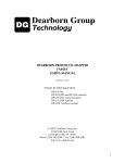
SRI-500
Scanning Laser Rangefinder with Inertial Image Stabilization
The SRI-500 Laser Rangefinder is an omnidirectional scanning
range image acquisition system for obtaining range images from
stationary or mobile platforms at distances up to 500 feet and
800,000 points per second. Scanning is a combination of fast
vertical scans at 500 lines/s combined with an azimuth sweep rate
o
of up to 1000 /s.
3D point datasets are acquired by setting vertical and horizontal
sweep rates, and commanding acquisition of a sequence of vertical
scan lines through a specified elevation and azimuth range. The
SRI-500 can be programmed to auto-cycle through an azimuth
region repeatedly, automatically reversing direction.
The SRI-500 communicates with a host via a TCP-IP connection. The host may issue Laser
Enable, Motor Speed, and Take Scan commands through software based on sample source code
provided with the scanner. Each scan consists of a sequence of nearly vertical scan lines taken
between start and stop platform azimuth and elevation angles. Elevation coverage may be
o
o
o
o
programmed from +65 to -65 and azimuth from +300 to -300 . The scan head is capable of two
complete rotations in azimuth, lock to lock, to maximize programming flexibility.
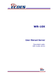
Optional Inertial Measurement Unit
In mobile applications, the optional internal
inertial measurement unit captures platform
vibration and rotation at 200 Hz and is used to
correct the 3D coordinates of each sample point
to
create a stabilized world referenced dataset.
Data for each scan is corrected to the initial
platform inertial orientation during acquisition.
Platform orientation and velocity changes
between and during scans are reported with each
scan, so multiple scans may be registered in a
world map and vehicle motion may be derived. In
static applications the internal IMU may be used to register earth vertical which provides absolute
orientation information for structures captured.
Page 17 of 20
Specifications
Scan Angles
Azimuth:
Elevation:
± 360
o
± 65
Scan Speed:
Vertical:
Horizontal:
500 lines/s max
o
1000 /s max
o
Measurement Acquisition Rate: Approx. 800,000 points/sec peak during vertical scan
Range Accuracy, 1σ
1.5 inches
Maximum Range, 85% Reflectance Lambertian Surface
500 feet
Minimum Range
3 feet
Laser Wavelength
905 nm
Eye Safety
Eye safe
Average Laser Power
< 1 mW
Laser Interlock
Vertical scan mirror encoder
Laser Spot Divergence
2 millirad H × 0.5 millirad V
Optical Aperture
2” × 8.5”
Scan Motors
Long life brushless DC
Azimuth Accuracy, Platform Relative
1.5 arc-min
Elevation Accuracy, Platform Relative
1 arc-min
Range Gating
Minimum and maximum range limits in increments of 12.5 feet from 3 to 500 feet.
Weight:
Power:
33 lb.
50 W, 12-28 VDC
Environmental
Enclosure
Operating Temperature
Storage Temperature
Shock and Vibration
Connectors
Optical Head
IP65 / NEMA-4 waterproof
-20 to 70 C shade, -20 to 50 C direct sun
-40 to 85 C
5G operating, 10G survival
Waterproof, UV resistant power and ethernet
Sealed, dry nitrogen filled
Inertial Measurement Unit Option
6-Axis quartz accelerometer/gyro AHRS system
Image Stabilization
o
Azimuth drift
0.05 /sec
o
Pitch/roll drift
0.02 /sec
Pitch/Roll Earth Vertical Attitude Accuracy
o
Stationary
0.1
o
Maneuvering Vehicle 0.5 typical
Page 18 of 20
Output Data
Physical Data Interface:
Application data rate:
Data Output:
Latency:
100 Base-T Ethernet
25.6 Mbit/s at max scan rate
Streaming scan packet data
100 milliseconds maximum
Scan Packet
Packet Header
Timestamp
Inertial Velocity Change from Previous Scan End
Inertial Azimuth Change From Previous Scan End
Point Sample Data
Range:
0.1 inch resolution, 0 to 6500 inches
o
Azimuth:
0.02 resolution
o
Elevation:
0.01 resolution
Relative Return Signal Strength
Time From Previous Sample
Packet Trailer
Timestamp
Inertial Velocity Change from Scan Start
Inertial Azimuth Change From Scan Start
Reference Coordinate Systems for Output Data
With Inertial Option
Elevation angle relative to Earth Vertical
Azimuth relative to platform orientation at start of scan
OR relative to instantaneous platform orientation
Without Inertial Option Elevation and azimuth relative to instantaneous platform orientation
Command Set
Set Azimuth Scan Speed
Set Elevation Scan Speed
Take Single Scan
Take Repeating Scans (Auto-reverse in azimuth)
Laser Enable
Halt Scan
o
Maximum Scan Duration: 10,000 vertical lines (20 seconds), up to 600 azimuth
Minimum Scan: 1 vertical line (2 milliseconds)
Page 19 of 20
Page 20 of 20