1
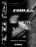
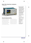
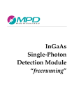
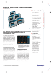
Abberior Instruments
Pulsed Diode Laser
PDL 561 / PDL 594
Operating Manual
Last change: 2015-04-08
Subject to change without notice.
Page 1/14
Contents
1 Introduction _________________________________________________________________________ 3
2 Laser Safety _________________________________________________________________________ 3
2.1 Safety Features __________________________________________________________________ 3
2.1.1 Interlock ____________________________________________________________________ 3
2.1.2 Manual Shutter (Optional) _____________________________________________________ 3
2.1.3 Key Switch __________________________________________________________________ 4
2.1.4 Status LEDs _________________________________________________________________ 4
2.1.5 Warning Labels ______________________________________________________________ 4
2.2 Safety Precautions ________________________________________________________________ 4
3 Operating Instructions _________________________________________________________________ 5
3.1 Laser Installation _________________________________________________________________ 5
3.1.1 Package Contents ____________________________________________________________ 5
3.1.2 Mounting the Laser Head ______________________________________________________ 5
3.1.3 Electrical Connections _________________________________________________________ 5
3.2 Startup Procedure ________________________________________________________________ 6
3.3 Power Modulation (Pulsed Mode) ____________________________________________________ 6
3.4 Fiber Coupling ___________________________________________________________________ 6
3.5 Continuous-Wave (CW) Operation ___________________________________________________ 7
3.6 Temperature Adjustments _________________________________________________________ 7
4 Trouble Shooting _____________________________________________________________________ 7
5 Specifications ________________________________________________________________________ 8
6 Dimensions _________________________________________________________________________ 10
7 Pin Assignments _____________________________________________________________________ 11
7.1 Laser Head Connector ____________________________________________________________ 11
7.2 Power Connector ________________________________________________________________ 11
7.3 Interlock Connector ______________________________________________________________ 11
8 EC Declaration of Conformity __________________________________________________________ 12
9 Warranty ___________________________________________________________________________ 13
9.1 Restriction of Warranty ___________________________________________________________ 13
9.2 Intellectual Property _____________________________________________________________ 13
10 “End of Life” Policy (WEEE) ___________________________________________________________ 13
10.1 Waste treatment on your own responsibility _________________________________________ 14
10.2 Ecological background __________________________________________________________ 14
11 Disclaimers ________________________________________________________________________ 14
Last change: 2015-04-08
Subject to change without notice.
Page 2/14
1 Introduction
With its PDL series of lasers, Abberior Instruments offers picosecond pulsed laser modules mainly
targeted for applications in fluorescence imaging and time-resolved spectroscopy including timecorrelated single-photon counting (TCSPC). The lasers are triggered from an external source, for example
from a second pulsed laser system or a pulse/delay generator. Alternatively, they offer continuous-wave
operation.
The lasers are offered as stand-alone units or as part of an Abberior Instruments microscope
system. In the first case, the laser is delivered with a small table-top control unit containing the controls
for its operation (power switch, key switch, status LED's) and an external power supply. If the laser is
ordered as part of a microscope system, the controls are integrated into the 19" electronics rack.
Fig. 1. Stand-alone control unit for the PDL laser head.
2 Laser Safety
LASER RADIATION
AVOID EXPOSURE TO BEAM
CLASS 3B LASER PRODUCT
The Abberior Instruments PDL lasers are Class 3B (IEC) laser products that emit
less than 500 mW of laser radiation in the visible spectral range.
2.1 Safety Features
2.1.1 Interlock
The laser is equipped with an interlock circuit that prevents current flowing through the diode
unintentionally.
2.1.2 Manual Shutter (Optional)
PDL laser heads purchased as stand-alone units are equipped with a manual safety shutter. For safety
Last change: 2015-04-08
Subject to change without notice.
Page 3/14
reasons but also to protect the optics from dust it is recommend to close the shutter whenever the laser
is not in use.
2.1.3 Key Switch
The stand-alone versions of the PDL come with a control unit which must be connected for the laser to
operate. When the key is in the '0' position, the diode is prevented from emitting. The key must be
actively turned to the '1' position each time the laser is powered on.
2.1.4 Status LEDs
The control box which is part of the stand-alone version includes information LEDs which displays
whether power is connected, the laser is on. The 'Laser Emission' LED indicates that the device is
emitting or could emit light.
2.1.5 Warning Labels
The laser head has yellow laser warning labels clearly indicating the beam aperture and specifying the
wavelength and optical power emitted from the laser head.
2.2 Safety Precautions
•
Eye and skin exposure to direct or reflected laser light is hazardous and may be extremely
harmful. Always wear eye protection appropriate to the beam wavelength and intensity. The
device must only be operated by properly trained personnel with experience in laser handling, in
a laboratory environment and with access to adequate laser safety equipment. The laser module
clearly displays a yellow warning label that shows the location of the laser beam aperture. This
label must be visible unless the laser beam is totally enclosed.
•
Always switch off the laser controller before moving or removing the laser head.
•
Always install the laser system to a properly grounded power outlet because the laser is sensitive
to electrostatic discharge (ESD).
•
Always mount the laser head in a way that the laser beam cannot cause any eye damage. Use
beam stops where appropriate. If the laser is fiber coupled make sure the fiber coupler is
attached securely to the laser head.
•
The laser head does not contain any user-servicable components and must not be opened by the
user at any time. Please note that any warranty is void when the laser head or the controller box
is opened.
Last change: 2015-04-08
Subject to change without notice.
Page 4/14
3 Operating Instructions
Caution — use of controls or adjustments or performance of procedures other
than those specified herein may result in hazardous radiation exposure.
3.1 Laser Installation
3.1.1 Package Contents
Before proceeding with the installation of the laser please check that the package you received is
complete. It should contain the follow items:
1
Laser head
1
Laser control unit
1
Power supply (input: 100–240 VAC, 1 A, 50–60 Hz, output: 24 V, 30 W)
1
Interlock shunt
2
Keys
1
D-Sub cable, 9 pins
1
Power cable
1
User manual
(If you received the laser as part of an Abberior Instruments microscope system, the components are
included in the electronics unit.)
3.1.2 Mounting the Laser Head
The laser head provides mounting threads for both horizontal and vertical installation which allows it to
be used with its polarization oriented vertically or horizontally. When mounted horizontally (the logo is
upright on the right-hand side of the laser head) the polarization of the laser beam is horizontal.
3.1.3 Electrical Connections
1. Connect the laser control box with the laser head using the supplied 9-pin cable.
2. Connect the external trigger source to the SMA connector on the back of the laser head (pulsed
operation only).
3. Connect the interlock input of the laser control box to an external interlock switch (e.g. of a
laboratory interlock system) or, if not used, place the provided interlock shunt into the interlock
socket.
4. Connect the 24 V power supply to the laser control box.
The remaining SMA connectors on the laser control box are not required for the operation of the laser
and, if not used, should be left disconnected. In this case, the laser operates in pulsed mode at its
maximum output power.
Last change: 2015-04-08
Subject to change without notice.
Page 5/14
The use and function of the CW Mod., Temp. Ctrl. and Analog Mod. inputs is described in later sections of
this manual.
3.2 Startup Procedure
1. Turn on the power switch to the "I" position. The Power LED should light up.
2. Turn the key switch to the "1" position. The Laser Emission LED should light up. If a trigger signal
is provided, the laser should now be emitting.
3. If the laser head is equipped with a manual safety shutter (stand-alone version only), open the
shutter as follows:
3.3 Power Modulation (Pulsed Mode)
When the laser is operated in pulsed mode, the pulse energy can be adjusted using the Analog Mod. input
on the back of the laser control unit. In order to use the power adjustment a control voltage between
0 and 5 V must be applied to the Analog Mod. SMA connector. Please note that the maximum output
power is reached at approx. 2.85 V and decreases again when then control voltage is further increased.
3.4 Fiber Coupling
Abberior Instruments offers the PDL as a free-space laser. However, the laser beam may be coupled into a
singlemode or polarization maintaining optical fiber. On the front face, the laser head has four M2.5
threads for the direct attachment of a fiber coupling unit, e. g. from the 60 SMS series (with mounting
adapter) by Schäfter & Kirchhoff. To mount a fiber coupler the manual safety shutter has to be removed
first.
Last change: 2015-04-08
Subject to change without notice.
Page 6/14
3.5 Continuous-Wave (CW) Operation
In order to operate the PDL in cw mode, the Temp. Ctrl. input must be tied to GND or set to a 0 V input.
Otherwise, the laser does not operate at its optimum and the output power will not exceed 200 – 300 µW.
The output power in CW mode can be controlled using the CW Mod. input on the back of the laser control
unit. A control voltage between 0 and 5 V must be applied to adjust the laser output power. It is normal
that the laser output power decreases again after the maximum power has been reached and the control
voltage is further increased.
Note:
No trigger pulses should be applied while the laser is operated in cw mode as they may cause a
power modulation.
3.6 Temperature Adjustments
The PDL laser contains temperature-sensitive devices, and in order to run at full power the operating
temperature must be kept constant. At the factory, the laser is carefully adjusted for optimal
performance at room temperature (21 °C). Usually, the temperature setting does not need any
adjustments and the Temp. Ctrl. input on the control unit can be left open. If the laser is operated at
significantly higher environmental temperatures or a drift in the temperature setpoint has occured the
temperature may be controlled externally.
If the laser is not running at its specfified output power, a temperature control voltage between 0 and 5 V
may be applied to the Temp. Ctrl. SMA input. Place a laser power meter in front of the laser aperture and
adjust the temperature control voltage until the maximum output power is achieved. Typically, a voltage
near 3.2 V gives the best performance.
4 Trouble Shooting
Problem
Possible solution
The laser does not emit.
a) Make sure the interlock input is closed.
b) Check that the trigger pulses are within the
specified range.
The maximum laser power in CW mode remains Make sure the Temp. Ctrl. input is tied to GND.
far below the specifications.
Last change: 2015-04-08
Subject to change without notice.
Page 7/14
5 Specifications
General Specifications
Operation mode
pulsed or cw
Wavelength
PDL 561:
PDL 594:
Temperature control input:
0–5V
Polarization:
horizontal
Polarization extinction ratio:
1 : 1000
Beam divergence (FWHM):
10° / 5 ° (θ⊥ / θ||)
Output beam quality (M²):
1.2
(561 ± 2) nm
(594 ± 2) nm
Pulsed Operation
Repetition rate:
0 – 100 MHz
Average power:
> 100 µW @ 40 MHz (130 µW typ.)
Pulse energy:
> 2.5 pJ (3 pJ typ.)
Pulse length:
< 150 ps (100 ps typ.)
Pulse trigger:
external
Trigger pulse amplitude:
2–5V
Trigger pulse length (FWHM):
< 5 ns
Trigger pulse rise time:
< 2 ns
Analog modulation input:
0–5V
Continuous Wave (CW) Operation
Output power:
2 mW (5 mW max.)*
CW control input:
0 – 10 V
* The PDL must not be operated at output powers above 2 mW for extended periods of time.
Power Supply
Power supply (controller unit):
24 V, 1 A
Power supply (laser head):
+5 V, 100 mA
+12 V, < 500 mA
Power consumption:
<5W
Operating Conditions
Last change: 2015-04-08
Subject to change without notice.
Page 8/14
Environment:
For indoor use only
Ambient temperature:
21 °C
Relative humidity:
< 80 % at 30 °C
Mechanical Specifications
Dimensions (L × W × H):
86 mm × 50 mm × 50 mm (laser head with manual shutter)
78 mm × 50 mm × 50 mm (laser head without shutter)
124.4 mm × 103 mm × 53.2 mm (control unit)
Weight:
365 g (laser head)
360 g (control unit)
Last change: 2015-04-08
Subject to change without notice.
Page 9/14
6 Dimensions
Last change: 2015-04-08
Subject to change without notice.
Page 10/14
7 Pin Assignments
7.1 Laser Head Connector
1
3
2
6
7
5
4
8
9
SUB-D connector, male, 9 pins
(view onto laser head)
Pin Function
Absolute Maximum Ratings
Min
Max
–0.3 V
40 V
1
+12 V Supply Voltage
2
+5 V
0V
5.5 V
3
Analog Modulation
–8 V
10 V
4
Laser Status Output
2.5 V
5.5 V
5
Interlock+
GND
High Z
6
CW Control
–15 V
15 V
7
Temperature Control
–8 V
10 V
8
GND
GND
GND
9
Interlock– (GND)
GND
GND
7.2 Power Connector
Pin
IP 40, 8 pin
Voltage
1
GND
2
N.C.
3
N.C.
4
N. C.
5
N. C.
6
GND
7
GND
8
+24 V
7.3 Interlock Connector
Interlock− (GND)
Interlock+
Last change: 2015-04-08
Subject to change without notice.
Page 11/14
8 EC Declaration of Conformity
Manufacturer:
Abberior Instruments GmbH
Address:
Hans-Adolf-Krebs-Weg 1
37077 Göttingen
Germany
Product:
Pulsed Diode Laser PDL 594 / PDL 561
We declare that the listed product complies with the following European Directives:
• 2004/108/EG Directive on Electromagnetic compatibility
• 2006/95/EG Directive on Low-voltage equipment
The product conforms to the standards:
• EN61326-1 (2006) Electrical equipment for measurement, control and laboratory use – EMC
requirements – part1 general requirements
• EN61010-1 (2001) Safety requirements for electrical equipment for measurement, control and
laboratory use – part1 general requirements
• EN60825-1 (2007) safety of laser products – part1 equipment classification and requirements
This declaration shall be ceased to be valid if any modifications are made to the product without our
approval.
Göttingen, Germany
Manager
2014-09-11
Gerald Donnert
Last change: 2015-04-08
Subject to change without notice.
Page 12/14
9 Warranty
Abberior Instruments GmbH warrants dedicated hardware parts of the PDL for a period of 12 months
starting with the date of shipment. The hardware warranty covers the laser head and the control unit.
During this warranty period Abberior Instruments will see to defaults by repair or by exchange if these are
still entitled to warranty. In case that for warranty repairs or service the unit must be sent back to
Abberior Instruments, the customer will carry the shipping costs back to Abberior Instruments. In case of
warranty repairs Abberior Instruments will carry the shipping costs back to the customer. If after
inspection of the parts for repair no warranty repair is applicable the customer will also carry the costs
for back shipment. If the unit is sent back to Abberior Instruments from abroad the customer will carry all
shipping costs, duties etc. which should arise for sending the goods back to Abberior Instruments.
Abberior Instruments warrants the hardware and software determined by Abberior Instruments for this
unit to operate without fault provided that they are handled according to our statements. However,
Abberior Instuments does not warrant a fault free or uninterrupted operation of the unit, of the software
or firmware for special applications nor this operation manual to be fault free. We will not carry
responsibility for ensuing damages.
9.1 Restriction of Warranty
The aforementioned warranty does not cover errors and defects being the result of improper treatment,
software and interface not supplied by us, modification, misuse or operation outside the defined
ambient conditions stated by us or unauthorized maintenance.
Abberior Instruments reserves the right to change this operation manual or the technical data of the
described unit at any time.
9.2 Intellectual Property
Any changes of the beam path or any addition of new laser sources might conflict with local, third party
intellectual property. The owner has to make sure that no local, third party IP is violated when changing
the configuration of the system.
10 “End of Life” Policy (WEEE)
As required by the WEEE (Waste Electrical and Electronic Equipment Directive) of
the European Community and the corresponding national laws, Abberior
Instruments offers all end users in the EC the possibility to return “end of life”
units without incurring disposal charges.
This offer is valid for Abberior Instruments electrical and electronic equipment provided that it was sold
to a company or institute within the EC and still complete, not disassembled and not contaminated. Leftover parts such as PCB’s, housings etc. are excluded from the take back service.
If you wish to return an Abberior Instruments unit for waste recovery, please contact Abberior
Instruments GmbH for further information.
Last change: 2015-04-08
Subject to change without notice.
Page 13/14
10.1 Waste treatment on your own responsibility
If you do not return an “end of life” unit to Abberior Instruments, you must hand it to a company
specialized in waste recovery. Do not dispose of the unit in a litter bin or at a public waste disposal site.
10.2 Ecological background
It is well known that WEEE pollutes the environment by releasing toxic products during decomposition.
The aim of the European RoHS directive is to reduce the content of toxic substances in electronic
products in the future.
The intent of the WEEE directive is to enforce the recycling of WEEE. A controlled recycling of end of live
products will thereby avoid negative impacts on the environment.
11 Disclaimers
Abberior Instruments will assume no responsibility for damage incurred by faulty customer equipment,
such as measurement equipment, cables etc, used in conjunction with Abberior Instruments lasers.
Abberior Instruments makes no warranty of any kind with regard to the information contained in this
guide, included but not limited to, implied warranties of merchantability and suitability for a particular
purpose. Abberior Instruments shall not be liable for errors contained herein nor for incidental or
consequential damages from the furnishing of this information. No part in this manual may be copied,
reproduced, recorded, transmitted, or translated without the express written permission by Abberior
Instruments.
Abberior Instruments GmbH
Hans-Adolf-Krebs-Weg 1
37077 Göttingen
Germany
phone +49 551 30724–170
fax: +49 551 30724–170
www.abberior-instruments.com
[email protected]
Last change: 2015-04-08
Subject to change without notice.
Page 14/14