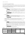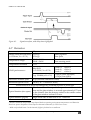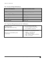
1
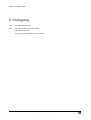
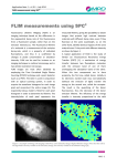
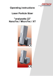
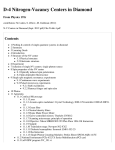
InGaAs Single-‐‑Photon Detection Module “freerunning” USER MANUAL VERSION 4.0.2 – SEPTEMBER 2014 Micro Photon Devices S.r.l. – Italy All Rights Reserved MICRO PHOTON DEVICES InGaAs Single-Photon Detection Module Free-Running version © Micro Photon Devices S.rl. -‐‑ GmbH Via Stradivari, 4 • Stradivari Strasse, 4 39100 Bolzano -‐‑ Bozen, BZ • Italy Phone +39 0471 051212 • Fax +39 0471 501524 Table of Contents 1 Getting Started .......................................................................................... 1 1.1 1.2 1.3 1.4 1.5 1.6 Introduction ............................................................................................... 1 The photon detection module ................................................................... 2 The Control Unit’s Front Panel ................................................................. 4 The Control Unit’s Rear Panel .................................................................. 5 The InGaAs/InP Single-Photon Avalanche Diode .................................... 6 Bibliography .............................................................................................. 8 2 The Control Software ................................................................................ 9 2.1 2.2 2.3 2.4 2.5 Software Installation and Startup .............................................................. 9 Start Tab ................................................................................................. 10 Menu bar................................................................................................. 12 Module Tab ............................................................................................. 15 The Summary Tab .................................................................................. 22 3 Using the InGaAs Module ....................................................................... 23 3.1 3.2 3.3 3.4 Powering on/off and operating the InGaAs module ................................ 23 Basic Setups ........................................................................................... 26 Troubleshooting ...................................................................................... 29 Bibliography ............................................................................................ 35 4 Specifications .......................................................................................... 36 4.1 4.2 4.3 4.4 4.5 4.6 4.7 4.8 4.9 Instrument Input (Trigger IN) .................................................................. 36 Instrument LVTTL Outputs (Trigger Out – Valid Gate) ........................... 36 Instrument NIM Output (Photon Out) ...................................................... 37 Internal Trigger ....................................................................................... 37 Gate Window and Hold-Off programmability .......................................... 37 Signal Propagation Times....................................................................... 38 Detector .................................................................................................. 39 General Specifications ............................................................................ 40 System Requirements for Software ........................................................ 40 5 Changelog............................................................................................... 41 Micro Photon Devices S.r.l. – Italy All Rights Reserved i G E T T I N G 1 Chapter S T A R T E D 1 Getting Started This chapter provides the introduction on the MPD InGaAs Single-‐‑ Photon Detection Module that will help you get acquainted with the product. It also includes the installation and configuration procedures that will support you in getting started with the system. 1.1 Introduction The InGaAs single-‐‑photon detection module is built around a Peltier cooled InGaAs/InP Single-‐‑Photon Avalanche Diode (SPAD) for the detection of near-‐‑infrared single photons from 900 nm up to 1700 nm. The module includes a programmable frequency and pulse generator for gating the detector, a front-‐‑end circuit for photodetector’s avalanche sensing, a fast circuit for detector’s avalanche current quenching and operative bias voltage resetting and some sub-‐‑circuits for signal conditioning. All the main parameters are adjustable by the user through the software interface, in order to match the requirements of the different applications. The system is composed by two parts: • • A Detection Head which comprises of a InGaAs/InP SPAD detector and the related fast electronics. Its small dimension allows its easy integration in all experimental setups. The detection head can be of two types: Gated-‐‑mode or Free-‐‑ running. A Control Unit which contains the pulse generator, the Peltier controller, the communication system and the power supplies of the entire module. The control unit is the same for both types of detection heads. They are connected together through a 2 m long wide-‐‑bandwidth cable. The system can be conveniently used both for counting and timing measurements, since the high performance electronics guarantees a clean temporal response even with fast gate transitions. Micro Photon Devices S.r.l. – Italy All Rights Reserved 1 G E T T I N G S T A R T E D 1.2 The photon detection module 1.2.1 Standard module configuration A standard InGaAs Single-‐‑Photon Detection Module is usually shipped with these parts: • Control Unit; • Detection Head (either with a fiber-‐‑pigtailed SPAD or with the detector placed behind a standard glass optical window) ; • Orange wide-‐‑bandwidth Cable for Control Unit to Detection Head connection; • MPD universal optical table adaptor for Detection Head mounting (optional); • Power cord; • USB key containing the installation software and the user manual in PDF® format; • A SPAD test report. Figure 1.1. A standard configuration for the InGaAs/InP single photon detection module. 1.2.2 Preparation for use and care. Before using and powering-‐‑on the module the following precautions must be followed: 1. The InGaAs Single-‐‑Photon Detection Module, MUST be unpacked and set-‐‑up as reported in paragraph 3.1.1. Micro Photon Devices S.r.l. – Italy All Rights Reserved 2 G E T T I N G S T A R T E D 2. NEVER switch-‐‑off the module if the SPAD has not being turned off by the control software as explained in paragraph 3.1.4 3. Avoid switching on the module if the orange wide-‐‑bandwidth cable has not been properly connected to both the Control Unit and the Detection Head. 4. Never un-‐‑connect the orange wide-‐‑bandwidth cable if the module is powered-‐‑on. 5. In order to use the module, the controller software has to be installed on a PC, following the instructions in paragraph 2.1. 6. Before connecting any cable to the front panel connectors make sure that signals are compatible with the levels specified in Chapter 4. Also pay attention on signals polarity and invert them if necessary. 1.2.3 Care of the SPAD optical interfaces Please follow these instructions for fiber care: 1. avoid any unnecessary force that may cause the fiber to bend sharply and break; 2. bare fiber should not support the weight of the connector; 3. cap end face when connector is not in use; 4. inspect the end face of the fiber for dust or imperfections with a fiber microscope; 5. clean any dirt from the end face with a lint-‐‑free wipe. Please follow these instructions for the cleaning the window optical interface of your detection head: 1. Dust and other loose contaminants usually should be blown off before any other cleaning technique is employed. A canister of inert dusting gas or a blower bulb is needed for this method; 2. Do not use your mouth to blow on the surface because it is likely that droplets of saliva will be deposited on the optical surface. 3. If blowing off the surface of the optic is not sufficient, other cleaning methods and materials are acceptable. When cleaning an optic, always use clean wipes and optical grade solvents to prevent damage from contaminants. Wipes should always be moist with an acceptable solvent and never used dry. Acceptable wipes are pure cotton, lens tissue; 4. Typical solvents employed during cleaning are distilled water and isopropyl alcohol. Use all solvents with caution since most are poisonous, flammable, or both. Read product data sheets and MSDS sheets carefully before using any solvents; 5. If repeated cleaning is required it is recommended the use of distilled water to be used more frequently than the cleaning fluid and to apply the smallest amount of pressure when wiping the surface with lens tissue paper; Micro Photon Devices S.r.l. – Italy All Rights Reserved 3 G E T T I N G S T A R T E D 1.3 The Control Unit’s Front Panel 1 2 3 4 The control unit is the same independently on the type of the Detection Head (free running or gated). 1. PHOTON OUT : output, SMA connector; a digital pulse is generated for each detected photon; the output is a NIM pulse, which means that it must be 50 Ω terminated and that the low logic level is 0 V and the high logic level is -‐‑800 mV. The falling edge of the pulse marks, with very low jitter, the photon arrival time; 2. VALID GATE : output, SMA connector; outputs the effective SPAD status: it is in the high logic level when the SPAD is ON or in the low logic level when the SPAD is OFF due to the hold-‐‑off. The output conforms to a LVTTL standard; 3. TRIGGER OUT : output, SMA connector; (USE ONLY when a GATED MODE detection head is attached) outputs the internal trigger reference signal used to periodically enable the SPAD. Normally disabled, it is enabled only when internal trigger is selected from the user interface. The pulses are LVTTL standard; 4. TRIGGER IN : input, SMA connector; (USE ONLY when a GATED MODE detection head is attached) if an external trigger is needed, then the signal must be connected to this input. The external trigger signal can be positive or negative within the range from -‐‑2 V to +2.5 V and the internal comparator allows for a programmable threshold. For a complete understanding of module input and outputs and their absolute maximum ratings please refer to Chapter 4. Micro Photon Devices S.r.l. – Italy All Rights Reserved 4 G E T T I N G S T A R T E D 1.4 The Control Unit’s Rear Panel 4 3 1 5 6 2 1. USB Connector : 2. Detection Head cable connector : holds the USB type-‐‑B cable for PC connection; holds the wide-‐‑bandwidth cable for Detection Head and Control Unit connection; 3. Power Switch : used to switch on and off the module; 4. Fuse Holder : contains the 1 A fuse, to protect this appliance; 5. Power Inlet : hold the power cord to supply the unit; 6. Fan opening : permits the air to recirculate into the unit. Note Be careful during the module power off sequence: ALWAYS remember to turn off the detector using the control software as described in paragraph 2.4.1 before switching off the module using the Power Switch. Incorrect shutdown procedure can irreparably damage the SPAD detector. Micro Photon Devices S.r.l. – Italy All Rights Reserved 5 G E T T I N G S T A R T E D 1.5 The InGaAs/InP Single-Photon Avalanche Diode The core of this module is a Single-‐‑Photon Avalanche Diode (SPAD), housed into the Detection Head. The detector has a 25 µμm diameter active area and it is mounted on the top of a three-‐‑stage Peltier cooler. A SPAD is a p-‐‑n junction, biased well above the breakdown voltage (VB), that stays in a meta-‐‑stable state with no current flowing. At this bias, the electric field is so high that a single charge carrier injected in the depletion layer can trigger a self-‐‑ sustaining avalanche [1]. The current rises swiftly (nanoseconds or sub nanosecond rise-‐‑time) to a macroscopic steady level, in the milliAmpere range. If the primary carrier is photo-‐‑ generated, the leading edge of the avalanche pulse marks the photon arrival time. The current continues to flow until the avalanche is quenched by lowering the bias voltage down to or below VB. Then the bias voltage must be restored, in order to detect another photon. These operations are usually performed by a suitable circuit named Active Quenching Circuit (AQC) [2]. The device primary source of internal noise consists in a random dark-‐‑counting rate (DCR) arising from free carriers thermally generated. These events compete with photons in triggering the detector and thus impair the signal to noise ratio [3]. The Peltier cooler is therefore useful to lower the temperature of the detector in order to diminish this effect. Normally single photon detectors are operated in the so-‐‑called free-‐‑running mode, where the devices is enabled immediately after the quenching of each avalanche current. Normally this is true for Silicon SPADs but for InGaAs SPADs the DCR would be so high that the use of these detectors would be almost impossible. As a consequence, for further reducing these unwanted counts, the InGaAs SPADs are operated in gated regime: the detector is periodically enabled for a short time window called Gate, of duration 𝑇!" (Gate Width), whereas it is usually held off at a bias slightly below the breakdown voltage. However a secondary source of noise exists in SPADs: the afterpulsing. During the avalanche some carriers are captured by deep levels in the junction depletion layer and subsequently released with a statistically fluctuating delay. Released carriers can retrigger the avalanche, generating afterpulses correlated with a previous avalanche pulse which sum up with the DCR. In order to mitigate these avalanche re-‐‑triggerings, after each avalanche, during the subsequent gating occurrences, the detector is kept off for a user programmable time, named hold-‐‑off time, 𝑇!" . In this way the trapped carriers can be released without triggering further avalanches. The hold-‐‑off time is particularly useful when cooling the detector since the afterpulsing effect worsens at low temperatures because the decay times of the trapped carriers increase. Despite the fact that usually InGaAs SPADs are operated in gated-‐‑mode, in case of particularly good devices it is possible to bias them also in free-‐‑running mode as with Silicon SPADs. The main difference is related to the fact that in case of InGaAs SPADs the afterpulsing effect is much higher and the time constants have values in the range of Micro Photon Devices S.r.l. – Italy All Rights Reserved 6 G E T T I N G S T A R T E D microseconds. As a consequence it is necessary to use hold-‐‑off in the order of few or few tens of microseconds. Now, due to the hold-‐‑off time the SPAD has a linear working range, which means that the number of detection events within a defined time period (T) depends linearly on the illumination intensity, only for photon fluxes much smaller than the reciprocal of the hold-‐‑off time. At large photon fluxes the number of detected photons deviates from linearity and saturates to a constant value, which is the reciprocal of the dead-‐‑time (THO). When the deviation from linearity is moderate (counting rates smaller than 1/(2𝑇!" )) it is possible to evaluate the deviation from linearity and to correct the measured counting rates as described here below. Supposing the Photon Detection Efficiency 100% for simplicity, Nimp the number of impinging photons on a SPAD active area during an integration time T, THO the hold off time and Ncounted the photons counted by the detector, Ncounted is equal to Nimp multiplied by the ratio of the actual integration time divided by the set integration time T (since every time the counter is triggered, it becomes “blind” for a time THO): 𝑁!"#$%&' = 𝑁!"# ∗ 𝑇 − 𝑁!"#$%&' ∗ 𝑇!" 𝑇!" = 𝑁!"# ∗ (1 − 𝑁!"#$%&' ) 𝑇 𝑇 thus 𝑁!"#$%&' = 𝑁!"# 𝑇!" 1 + 𝑁!"# ∗ 𝑇 𝑒𝑞. 1 By expressing Nimp as a function of Ncounted and dividing both sides by T, one obtains: 𝑁!"# 𝑁!"#$%&' 𝑇= 1− 𝑁!"#$%&' 𝑇 𝑒𝑞. 2 × 𝑇 !" 𝑇 This means that the actual photon counting-‐‑rate can be calculated simply by dividing the measured counting-‐‑rate divided by 1 minus the measured counting-‐‑rate multiplied by the hold-‐‑off. Normally instead of the hold-‐‑off the dead-‐‑time should be more correctly used since the dead time is the sum of the hold-‐‑off plus the time needed to quench and reset the SPAD [1]. Anyway in case of InGaAs diodes, the hold-‐‑off is so long compared to the quench and reset phased that they practically coincide. Please note that the previous equations do not take into account the Photon Detection Efficiency of the InGaAs module. These formulas also strictly apply when the photon rate is uniformly distributed over time. Micro Photon Devices S.r.l. – Italy All Rights Reserved 7 G E T T I N G S T A R T E D 1.6 Bibliography • SPADs and quenching circuits: [1] Cova, S., Ghioni, M., Lacaita, A. L., Samori, C., and Zappa, F. “Avalanche photodiodes and quenching circuits for single-‐‑photon detection”, Applied Optics, 35(12), 1956— 1976 (1996). http://dx.doi.org/10.1364/AO.35.001956 [2] Cova, S., Ghioni, M., Zappa, F., Rech, I., and Gulinatti, A., “A view on progress of silicon single-‐‑photon avalanche diodes and quenching circuits”, Proceedings of SPIE , 6372, pp. 63720I-‐‑1 -‐‑ 63720I-‐‑12 (2006). http://dx.doi.org/10.1117/12.685963 • InGaAs/InP SPADs: [3] Alberto Tosi, Alberto Dalla Mora, Franco Zappa and Sergio Cova, “Single-‐‑photon avalanche diodes for the near-‐‑infrared range: detector and circuit issues,” Journal of Modern Optics, 56:2-‐‑3, 299-‐‑308 (2008) -‐‑ http://dx.doi.org/10.1080/09500340802263075 [4] Alberto Tosi, Alberto Dalla Mora, Simone Tisa, Fabio Acerbi, Franco Zappa and Sergio Cova , “InGaAs/InP SPADs for near-‐‑infrared applications: device operating conditions and dedicated electronics,” Proc. SPIE 7681, Advanced Photon Counting Techniques IV, 76810R (April 28, 2010); http://dx.doi.org/10.1117/12.850696 • [5] Paper on the InGaAs Single-‐Photon Detection Module: Alberto Tosi, Adriano Della Frera, Andrea Bahgat Shehata, and Carmelo Scarcella, “Fully programmable single-‐‑photon detection module for InGaAs/InP single-‐‑photon avalanche diodes with clean and sub-‐‑nanosecond gating transitions,” Rev. Sci. Instrum. 83, 013104 (2012) -‐‑ http://dx.doi.org/10.1063/1.3675579 Micro Photon Devices S.r.l. – Italy All Rights Reserved 8 T H E C O N T R O L 2 Chapter S O F T W A R E 2 The Control Software This is the operator’s reference chapter which contains information about for the software front-‐‑panel of the InGaAs Single-‐‑Photon Detection Module. 2.1 Software Installation and Startup Complete the following steps to install the controlling software for Windows®: • Log in as system administrator or as a user with administration privileges. • Disable any automatic virus detection programs before you install. Some virus detection programs could interfere with installation. • Insert the USB key and copy the Install_for_Windows folder in a temporary location (for example your Desktop) • Double click on the file named setup.exe located inside the folder you just copied. • Follow the instructions on the screen until the installer ends. • Connect the module at the PC, with the procedure detailed in Chapter 3.1.1. • Windows® will automatically recognize the device and install the correct drivers. If a “found new hardware” window appears, select the option to automatically download recommended drivers from internet. For this reason, the computer on which the drivers will be installed, MUST BE CONNECTED to the internet. The drivers will create a virtual serial COM associated with the InGaAs/InP single photon counter. • Once completed, you can start the controlling software from Windows Start Menu Programs MPD InGaAs Single Photon Detection Module. • Remove the temporary install folder. Micro Photon Devices S.r.l. – Italy All Rights Reserved 9 T H E C O N T R O L S O F T W A R E 2.2 Start Tab When the software is started for the first time the window illustrated in Figure 2.1 is shown. This window will have two tabs the Start tab and the Summary tab. With the Start tab, it is possible to detect and name all the InGaAs Single-‐‑Photon Detection Modules attached to the PC where the controlling software runs. It consists of a Detected Modules table and two buttons: Autodetect and Accept Config. The Start tab has also a menu bar, which is always present and does not change independently on which tab is currently selected. This menu bar has three menus: File, Settings and Help. Figure 2.1. Start tab screenshot with one detected module. 2.2.1 Detected Modules table In this table are reported all the detected connected modules. For each ones the software displays the Detection Head and Control Unit Serial Numbers and, to simplify the system identification, a custom name can be assigned. By default the Custom Name corresponds to the Detection Head’s serial number and is linked to the Detection Head and saved in the PC, so it is recalled every time this specific Detection Head is connected to the PC. This is true even if the Detection Head is connected through a different Control Unit. Of course any name can be chosen as Custom Name. If the software has detected all the connected modules and the user has associated all the custom names, the Accept Config button can be clicked on. By accepting the configuration, the software will create additional tabs, one for each detected module as is shown in Figure 2.2. Micro Photon Devices S.r.l. – Italy All Rights Reserved 10 T H E C O N T R O L S O F T W A R E Figure 2.2. Start Tab schreenshot after module renaming and “Accept Config” button pressed. Each tab will allow the user the full control of the associated photon counter as will be shown in paragraph 2.4. This table is automatically populated at each software startup with actual connected modules, unless the user has disabled the automatically search feature in the ‘COM ports’ panel as will be explained in paragraph 2.3. If other modules are connected to the PC without first closing the program, it is necessary to manually press the Auto Detect button as explained into the following section. 2.2.2 Auto Detect button Pushing this button the software scans each COM port available on the system and sees if there is any attached module; then the Detected Modules table is updated according to the current scan. This function is automatically run when the program starts, unless you assign a static COM number in the Settings-‐‑>COM Ports configuration window. 2.2.3 Accept Config button By pressing this button the custom names, that have been assigned to the connected modules, are confirmed and the program populates the tabs with one page for each recognized system. Tabs report the Custom Name that has been given to each module. Micro Photon Devices S.r.l. – Italy All Rights Reserved 11 T H E C O N T R O L S O F T W A R E Figure 2.3. COM ports configuration window. 2.3 Menu bar The menu bar has three menus: File, Settings and Help. The File menu has only one item Exit and is used to exit immediately the program when the SPAD is turned off. By pressing the Settings menu two items are shown : COM ports and Advanced. By pressing the first item of the list a configuration window (shown in Figure 2.3) will appear. Inside this window there are the following controls: • Interface aspect radio button: it lets you to switch between multiple or single module interface. Using this last option, tabs are not shown and only one module can be managed. This option is very useful when only one photon counter has been attached to a single PC. • Search COM automatically checkbox: in Multiple modules interface mode always enabled. This option can be set as desired only if the software has been set in Single module interface mode. If disabled, it does not force the program, during the start-‐‑up, to find automatically the right COM port where a module is connected. This option is very useful when the PC handles other serial instruments that do not like the CS# command, sent by the program in order to detect connected modules. • Static COM number control: when the auto-‐‑detect checkbox is disabled, the COM port, to which the photon counter has been connected, must be specified in this field. • COM Exclusion List: it lists the COM port numbers that have to be excluded from the automatic detection process. Use comma as number separator. Note You have to restart the program in order to make the changes active. Micro Photon Devices S.r.l. – Italy All Rights Reserved 12 T H E C O N T R O L S O F T W A R E Figure 2.4. Advanced Settings. By pressing the second item of the Settings menu a configuration window (shown in Figure 2.4) will appear. Inside this window there are the following controls: • Keep Advanced Preset: when selected, the program retains the last Advanced Preset settings also when you temporary switch on other presets. Otherwise these settings are overridden. • Don'ʹt warn for Advanced Preset: deactivates the warning message when you switch to or you load an Advanced Preset. • Enable lower temperature down to 228 K: allows to set, as SPAD temperatures, values below 233 K but higher than 228 K. The use of the detector at such low temperatures is advised only for overvoltages equal to or lower than 5V, moderate count rates and when the detection head is mounted on a very good heat sink. In case the detection head cannot reliably keep such low temperature it will shut down itself with a warning. In this case it is advised either to use temperatures higher than 233 K or to improve the module heat dissipation. • Don'ʹt warn for temperature lower than 233 K: deactivates the warning message when you operate the SPAD at temperatures lower than 233 K. By pressing Help, on the menu bar, the menu shown in Figure 2.5 will appear. Figure 2.5. Help menu. Micro Photon Devices S.r.l. – Italy All Rights Reserved 13 T H E C O N T R O L S O F T W A R E Figure 2.6. Software Update (left) and User Manual update (right) dialogue boxes. The Help menu lists the following items: • About: when pressed a dialogue box showing the program name, version and copyright will appear. • MPD website: when pressed, the default web browser will open on the MPD webpage. • Gated Mode User Manual: when pressed the default PDF reader will be opened and the InGaAs user manual, for the Gated mode module version, will be shown. • Free running Mode User Manual: when pressed the default PDF reader will be opened and the InGaAs user manual, for the free-‐‑running mode module version, will be shown. • Check Updates automatically: when this item is “ticked”, on start-‐‑up, the InGaAs control software will look for software or user manual updates on the MPD website. o In case a new user manual is present, the dialogue box shown in Figure 2.6 on the right will appear and if the user presses the ‘Yes’ button the new user manual is downloaded and copied inside the program. A dialogue box signaling the successful install of the new manual will also be shown as illustrated in Figure 2.7. o In case a new software is available, the dialogue box shown in Figure 2.6 on the left will appear. If the ‘Yes’ button is pressed, the default web browser will be opened directly on the download page of the MPD website. Figure 2.7. Dialogue box informing that the Gated-‐‑Mode User-‐‑Manual has been downloaded. Micro Photon Devices S.r.l. – Italy All Rights Reserved 14 T H E C O N T R O L S O F T W A R E Figure 2.8. Module tab screenshot before turning on the SPAD. 2.4 Module Tab After clicking the Accept Config button, in the Start tab, the software creates a module tab for each attached system. The tab label reflects the Custom Name given at the specific module. Every module tab opens an interface whereby all the configurable parameters of the detector can be set. In Figure 2.8 it is reported a page screenshot, taken before turning ON the SPAD. The next paragraphs will describe all the controls, buttons and indicators that can be found into this window, divided by section. 2.4.1 Detection Module Control In this section of the panel there are two buttons: “Apply Settings and Turn On SPAD” and “Update Configuration” (Figure 2.8). The first button changes to “Turn Off the SPAD” after the InGaAs/InP SPAD has been turned on, as shown in Figure 2.9, and will revert to the first name after the turning off of the SPAD. The two buttons are used to upload the user-‐‑defined parameters in the control unit and turn on and off the detector. In particular: • Apply Settings and Turn On SPAD button: if the detector is off, you can select a SPAD preset (i.e. the operating temperature, excess bias and hold-‐‑off of the photodetector) from the SPAD Preset drop box menu. The only SPAD preset that allows to modify the SPAD settings is the Advanced preset (as shown in Figure 2.10). Completed this task, by pressing this button, all the settings are sent to the module and the detector turns on. Micro Photon Devices S.r.l. – Italy All Rights Reserved 15 T H E C O N T R O L S O F T W A R E Figure 2.9. Module tab screenshot after having turned-‐‑on the SPAD (with Better Timing preset). • Update Configuration button: this button becomes active only when at least one SPAD parameter has been changed after having pressed the ‘Apply Settings and Turn On SPAD’ button. The only SPAD preset that allows to modify the SPAD settings is the Advanced preset and SPAD presets can be changed only when the SPAD is in the OFF state. Thus this button becomes active only when the “Advanced” preset has been set and at least one SPAD setting has been modified after the turning ON of the diode. New values are uploaded simply by pressing this button. Values shown in the module tab, that do not correspond to the ones already loaded in the InGaAs module, because for example they have been just changed by the user, are highlighted in blue as shown in Figure 2.10. Finally, it is worth noting that any change of the SPAD settings may require a detector power off and a consequent power on transient that is carried out automatically by the module. • Turn Off SPAD button: if the SPAD is on, this button replaces the “Apply Settings and Turn On SPAD” one (as shown in Figure 2.9). In order to shut down the detector, this button must be clicked and the user has to wait until the SPAD status LED, in the “Module Status Overview”, is off. Note You MUST press Turn Off SPAD and WAIT until the SPAD status LED is off before switching off the complete module by using the power switch located on the module rear panel. If this procedure is not followed, the SPAD detector may be permanently damaged. Micro Photon Devices S.r.l. – Italy All Rights Reserved 16 T H E C O N T R O L S O F T W A R E Figure 2.10. Module tab screenshot after having turned on the SPAD and with the “Advanced” “SPAD preset” selected. Note that the temperature setting is ‘blue’ and that the “Update Configuration” button is active (current SPAD temperature = 245 K but the desired one is 233 K). 2.4.2 SPAD Settings With this panel you can select a SPAD configuration, that is a particular combination of detector temperature, excess bias and hold-‐‑off time. Under SPAD Preset drop list menu (shown in Figure 2.11) there are four preset configurations, which lead to different detector performances; in particular: • Lowest Noise : it sets almost the lowest achievable DCR at the expense of detection efficiency and timing resolution; • Low Noise : offers higher detection efficiency and still low DCR; • Better Timing : allows to obtain high efficiency and a good temporal response (low jitter) with moderate DCR; • Best Timing : gives you almost the best possible efficiency and timing jitter of the module at the expense of high DCR but still not the highest. SPAD Preset selection can be changed only when the detector is off. Thus you have to use the “Turn Off SPAD” button if the diode is active. Modifications are applied at the next start of the detector, i.e. using the “Apply Settings and Turn On SPAD” button. If you need a more specific configuration, there is the possibility to manually set the detector temperature, excess bias and hold-‐‑off time, by selecting the Advanced preset. With this preset, Micro Photon Devices S.r.l. – Italy All Rights Reserved 17 T H E C O N T R O L S O F T W A R E the Temperature, Excess Bias and Hold-‐‑Off controls, shown for example in Figure 2.9 and highlighted in Figure 2.12, become active and the user can enter the desired values. Figure 2.11. SPAD Preset configurations drop list menu. Figure 2.12. Advanced SPAD configuration, with fancy values. Normally these controls display the set values but do not allow their modification. In “Advanced mode”, instead, you can configure these three parameters into the range and with the steps defined in the Specifications chapter. By inserting a value outside these limits, the program automatically forces the nearest allowed maximum or minimum value. Unlike others preset, when the Advanced is selected, the SPAD parameters can be changed even when the detector is on and running. Modifications are applied by pressing “Update Configuration” button. This operation, according to the modified parameters, may require a SPAD turn off and a reactivation. Anyway this is automatically done by the module. 2.4.3 Module Status Overview In this panel, shown for example in Figure 2.10 and depicted in Figure 2.13, there are seven status LEDs, and four other indicators. The meaning of LEDs colors are: • TEC Controller LED: it turns yellow to indicate that the thermoelectric cooler has been powered on and the temperature is going to reach the desired steady state value. When the device reaches the right value, the LED becomes green. It is off while the TEC is inactive. It turns red if the desired temperature is not reached. • SPAD LED: it turns yellow to indicate the transient of the SPAD bias voltage to the correct value just below breakdown and green to point out the steady state of this one. When the bias is inactive, this LED is off. It turns red if the correct bias voltage cannot be reached. Micro Photon Devices S.r.l. – Italy All Rights Reserved 18 T H E C O N T R O L S O F T W A R E • GATE LED: it turns on with a green color when the SPAD is biased above breakdown; on the contrary it is inactive when the SPAD is biased below breakdown. This is true independently of the type of the used detection head (free-‐‑running or gated). • Detection Head LED: it turns red when there is no communication with the Detection Head or when the maximum Gate Width is not satisfied (external trigger). Otherwise it is green. • Control Unit LED: it turns red only when there is no communication with the Control Unit. Otherwise it is green. • System Ready LED: during the normal functioning of the whole system it is green; it turns red only when an error inside the module is detected. Others indicators in this section are: • CU SN : MPD serial number of the connected Control Unit. • DH SN : MPD serial number of the connected Detection Head. • SPAD Temp : the current temperature of the detector in Kelvin. It is active only when the TEC controller is active; in all the other cases it does not show anything. There is also a status bar at the bottom of the module window (shown for example in Figure 2.10): it reports the module loaded configuration or eventually the error messages. Figure 2.13. Module Status Overview indicators, during detector power on. Micro Photon Devices S.r.l. – Italy All Rights Reserved 19 T H E C O N T R O L S O F T W A R E Figure 2.14. Manage Module Configurations buttons. 2.4.4 Manage Module Configurations The InGaAs Single-‐‑Photon Detection Module automatically saves and recall at startup the last settings used, but sometimes it is more convenient to save different configurations for different setups. For this purpose you can use the Save to File or the Load from File buttons, shown in all the module tab pictures and highlighted in Figure 2.14. If one of these buttons is pressed, a standard save or load window appears and it is possible to create, overwrite or open an existing file in the preferred directory. All user data, including the SPAD settings, are stored in a single binary file any time the “Save to File” button is pressed. In order to force the software to recall and display the parameters currently set on the module, the Load from module button can be used. All previous unsaved data will be lost. Note At module startup, the last parameters, that have been successfully uploaded in the module, are automatically reloaded, shown and highlighted in blue, without the need of pressing the “Load from module” button. 2.4.5 Error control In case of errors the module tab will be framed in a red rectangle as shown in Figure 2.15. The module tab name will also turn red. A red LED in the Module Status Overview will mark the error type. Please refer to paragraphs 2.4.3 and 3.3 for a correct understanding of the various possible errors and for troubleshooting. In case of a communication error see immediately paragraph 3.3 before powering-‐‑off the module. In case of all the other errors the module turns off the SPAD and does not accept any more commands, thus it is necessary to switch off the module. Before switching it on and detecting it again, it is advisable to solve the cause of the error. In some rare cases it might happen that, after having turned off the SPAD, the SPAD LED remains orange indicating that the detector’s turning off procedure is taking longer than expected (see Figure 2.16). In this case please press the OK button to start an internal diagnostic routine. In case the tests will end successfully, the window shown in Figure 2.17 (left) will appear; please press OK to continue. In case the tests will end with a false alarm detection, the window shown in Figure 2.17 (right) will appear; please follow the indicated procedure in order to safely power off the module and reboot the whole detection system. Micro Photon Devices S.r.l. – Italy All Rights Reserved 20 T H E C O N T R O L S O F T W A R E Figure 2.15. Screenshot of a Module tab when an error is detected. Figure 2.16. Screenshot of a Module tab when a longer-‐‑than-‐‑expected SPAD turning off time is detected. Figure 2.17. Screenshots of Module tabs showing the results of the internal diagnostic routine triggered after a longer-‐‑than-‐‑expected SPAD turning off time. Test’s successful ending message is shown on the left while a false-‐‑alarm detection is shown on the right. Micro Photon Devices S.r.l. – Italy All Rights Reserved 21 T H E C O N T R O L S O F T W A R E 2.5 The Summary Tab The Summary tab (see Figure 2.18) illustrates all parameters that have been set for each currently connected module, in a single screenshot; furthermore it reports the status of every device. Since a maximum of four InGaAs Single-‐‑Photon Detection Modules can be connected to a single PC, there are four columns that are filled with the appropriate parameter/status, indicated by the row header. Since the InGaAs control SW is able to manage both free running and gated detection heads, the Summary Tab will indicate accordingly which detection head (DH) is a free running one and which one is gated, on the line named “Trigger Configuration”. This screen is only a summary, the values contained into the table cannot be modified in this tab; in order to change the parameters the correct Module Tab must be selected and the settings must be adjusted there. The Summary Tab is also only available when the software is in Multiple Module Mode, since in Single Module Mode all the reported information is already presented in the unique Module Tab present. Figure 2.18. Summary tab showing two connected modules one with a free running detection head and one with a gated one. Micro Photon Devices S.r.l. – Italy All Rights Reserved 22 U S I N G T H E I N G A A S 3 Chapter M O D U L E 3 Using the InGaAs Module In this chapter, examples of measurements and configuration procedures of the InGaAs Single-‐‑Photon Detection Module are presented. 3.1 Powering on/off and operating the InGaAs module The following paragraphs illustrate some simple measurements in order to become familiar with the correct use and operation of the MPD InGaAs Single-‐‑Photon Detection Module. 3.1.1 Preparation for use and powering on the module Once verified that all the items listed in paragraph 1.2.1 have been bought, it is possible to start preparing the system using the following simple steps: 1. Install the Detection Head in the optical setup, the use of the MPD universal optical table adapter is highly recommended. If the pigtailed version of the Detection Head has been bought, the loose end of the module fiber can be now connected, through the use of a barrel, to the FC/PC connector of the optical fiber coming from the experimental set-‐‑up. Before the connection please be sure to follow the care instruction listed in paragraph 1.2.3. 2. Connect the Detection Head to the Control Unit by using the orange wide-‐‑bandwidth cable and inserting it in the inlets present in the back panel of both devices. It must be ensured that the latches are both locked in the correct position. Take care in cable routing: minimum bend radius is 5 mm and first bend must be at almost 100 mm from the end connector. 3. Connect the power cord between the power inlet in the back panel of the Control Unit and the power line supply. 4. Connect the USB cable from the Control Unit to the PC. 5. Switch on the Control Unit, using the ON/OFF switch on the rear panel. Micro Photon Devices S.r.l. – Italy All Rights Reserved 23 U S I N G T H E I N G A A S M O D U L E After this last operation the fan starts rotating and the module is ready to accept commands from the PC controlling program. 3.1.2 Program start and device acquisition By following the instructions outlined in Chapter 2, the control software can be installed in the computer and then can be started. After the splash screen, reporting the software version number, the Start Tab will be shown. The software automatically searches the connected modules at startup so, when the splash screen disappears, all the connected modules should be displayed in the Detected Modules table as shown in Figure 2.1; if this does not happen, by clicking the AutoDetect button, it is possible to force the program to retry the search. For each connected module a custom name can be assigned. This is very useful for identifying the correct module inside the program when controlling two or more modules with one single program; however the serial number of both Control Unit and Detection Head is also reported inside the Module Tabs. When all the connected modules are reported into the table and named, the Accept Config button has to be pressed. Now the custom names are stored in the PC and a module tab for each connected module is created (see Chapter 2 for a more detailed explanation). 3.1.3 Device configuration and detector turn-on Before turning on the SPAD(s), for each tab relative to a connected module (or for the only visible window, when in Single Module Mode), these steps must be followed: 1. Make sure that Detection Head LED, Control Unit LED and System Ready LED are all green; they must remain green during all the system functioning. If not see the paragraph 2.4.3 and 3.3 for troubleshooting. 2. Select a SPAD Preset, using the menu shown in Figure 2.11. If the Advance Mode has been chosen, enter the desired device temperature, excess bias and hold-‐‑off time. Completed these operations the Apply Settings and Turn On SPAD button can be pressed. In the next seconds some status LED will be turned on, with the following sequence: 1. The TEC Controller LED will become yellow and then green; during the yellow phase the detector temperature, indicated by SPAD Temp field, will change from the current temperature (the ambient temperature if the detector has been left off for a long time) to the one that has been selected with SPAD Preset (or directly input in the Advanced mode). 2. The SPAD LED will become first yellow and afterwards green when the right bias voltage has been applied to the detector. Micro Photon Devices S.r.l. – Italy All Rights Reserved 24 U S I N G T H E I N G A A S M O D U L E 3. The GATE LED becomes green to indicate that the SPAD has been biased above breakdown. Now the module is ready to be used in the experimental set-‐‑up. During the module functioning, the trigger and gate parameters can be easily modified, simply by changing them and uploading them to the module through the Update Configuration button. Before changing the SPAD Preset currently in use, the SPAD must be tuned off by using the Turn Off SPAD button. 3.1.4 End of measure and powering off the module When the measurement ends and the InGaAs Single-‐‑Photon Detection Module is not needed anymore, the module must be powered down correctly in order to prevent detector damages. The correct procedure is the following one: 1. Press the “Turn Off SPAD” button and wait until the SPAD LED goes off. 2. Repeat this operation for any connected module thought the respective module tab. 3. When all the SPADs have been turned off, close the program. A message warns the user if there are modules still running when the software is closed. If this happens please go back to the software and turn off these SPADs or carefully read the following chapter 3.1.5 if you want use them in the standalone mode. 4. It is now possible to press the power switch, located in the back panel of each module, in order to physically switch off the module. 5. Before powering on again a Detection Module, please wait for at least 20 seconds. If the power switch is pressed before the closing of the software, a warning window will signal that there is a communication problem. This warning can, in this case only, be ignored. 3.1.5 Standalone module use (use with extreme caution) The InGaAs Single-‐‑Photon Detection Module can also be operated without a PC constantly connected. In fact when the module is properly configured and the detector is biased correctly, it can be detached from the PC, removing the USB cable, while it still runs: the module can work without the need of the PC connection. This is particularly useful when long measurements have to be performed and other instruments do not require a supervisor PC. However the customer must be extremely careful when this modality is used: the status of the module cannot be monitored through the control software and, since the detector is biased, the module cannot be switched off through the power switch. In order to safely power off the system, the module must be reconnected to the PC, detected with the procedure described in Chapter 3.1.2 and correctly turned off using the procedure described in Chapter Micro Photon Devices S.r.l. – Italy All Rights Reserved 25 U S I N G T H E I N G A A S M O D U L E 3.1.4 (otherwise the SPAD might be permanently damaged). If during the standalone functioning some errors occur, they will be reported after the device detection procedure. Note When the USB cable is detached form the module with a biased detector a Communication Error occurs: this errors signals that the module is still operating and that it has to be to reconnected later to the PC in order to turn the SPAD off correctly. 3.2 Basic Setups In this section simple test measurements are outlined and briefly explained. 3.2.1 Photon Counting setup Photon-‐‑counting is the simplest measurements performable with the module and Figure 3.1 shows a possible example of an experimental setup. It consists of a continuous wave laser that produces photons at 980 nm, properly attenuated, and a sample that absorbs photons and re-‐‑ emits in the near infrared range. These photons, properly collected, are sent to the SPAD detector (inside the Detection Head). The module does not need any particular configuration since it works in free running mode: its photon-‐‑out output is simply connected to a counter that counts the number of photons per seconds (i.e. counts per seconds, cps). The only thing to remember it that due to the long hold-‐‑off time (THO), the photon count rate differs from the module count rate. Figure 3.1. Simple setup for a photon-‐‑counting measure (green: optical signals, pink: electric signals). Micro Photon Devices S.r.l. – Italy All Rights Reserved 26 U S I N G T H E I N G A A S M O D U L E As explained in paragraph 1.5 (see it for details) the photon count rate (CRphoton) can be calculated from the module’s count rate (CR) with the following formula: 𝐶𝑅!!!"!# = 𝐶𝑅 1 − 𝐶𝑅 ∙ 𝑇!" 3.2.2 Photon Timing setup Another typical setup in which the InGaAs Single-‐‑Photon Detection Module is used is a photon-‐‑timing one, illustrated in Figure 3.2. This setup can be adopted for the measurement of fast waveforms of repetitive optical pulses. The technique is commonly known as Time Correlated Single Photon Timing (TCSPC) and is extensively described in ref. [1] and [2]. This setup consists of a pulsed laser source which excites a fluorescent sample that reemits photons with an exponential decay. In this example the laser is the source of the synchronization signal: its trigger-‐‑out signal is then, as START of a TCSPC system. The STOP signal to the TCSPC system is given by the photon out of the Control Unit: the STOP marks the arrival time of the detected photon at the diode. For example, in case of using a PicoQuant PicoHarp 300 [3], the laser sync is usually connected the Channel 0 input and the photon out is normally connected to the Channel 1 input. If the B&H SPC-‐‑130 [4] or similar cards are employed instead, please read carefully their manual because these cards work in the so called reverse mode. When connecting all the instruments it is very important to verify the voltage levels and the polarity of all the involved signals and to attenuate/invert them if necessary in order to comply with the inputs’ absolute maximum ratings. In order to ensure that the photons emitted by the sample impinge on the detector when the gate has been enabled, it is necessary to take particular care to the signal propagation delays inside the cables and in the instruments, included the InGaAs control unit (see Chapter 4 for the actual numbers). Figure 3.2. Simple setup for a photon-‐‑timing measure (green: optical signals, pink: electric signals). Micro Photon Devices S.r.l. – Italy All Rights Reserved 27 U S I N G T H E I N G A A S M O D U L E The TCSPC technique is normally adopted in order to correctly reconstruct the shape of the temporal response of fast pulses or a fast decaying fluorescence pulses (like in our example) by accurately measuring the photon arrival times and not simple measuring number of counts in a period of time. In order to do this, using the TCSPC technique, it must be guaranteed that only a single photon reaches the detector for every single laser pulse. This is commonly known in the scientific literature and is explained in ref. [1] and [2]. In order to avoid the pile-‐‑up effect [1] the detection rate of the laser trigger frequency must be lower than 5 % (or better 1%). Anyway, since in case of InGaAs modules the hold-‐‑off time is large, in the order of microseconds or even tens of microsecond, and also the DCR is in the order of kc/s, the calculation of the correct module count-‐‑rate to avoid pile-‐‑up is less straight forward. The key points to start are: • Module count rate should not be less than 5% of the laser frequency but only of the valid laser pulses, i.e. the ones that were shined when the module was in the ON state; • The DCR (dark-‐‑counting rate) should be subtracted since it is the signal count-‐‑rate that should be less than 5% of the valid laser pulses. Thus, being CR the module counting rate, Valid the number of valid laser pulses over an integration time T, flaser the laser frequency, flaser-‐‑valid the equivalent laser frequency considering only the valid laser pulses, THO the hold-‐‑off time, 𝐷!"#$% = 1 𝑓 , one can !"#$% write the following equations: 𝑉𝑎𝑙𝑖𝑑 = 𝑓!"#$%!!"#$% ∙ 𝑇 = 𝑓!"#$% ∙ 𝑇 − 𝐶𝑅 ∙ 𝑇!" ∙ 𝑇 𝐷!"#$% 𝑓!"#$%!!"#$% = 𝑓!"#$% − 𝐶𝑅 ∙ 𝑇!" ∙ 𝑓!"#$% Then, since the module counting rate is the sum of the DCR and the signal counting rate and it is only the latter that has to be less than, for example, 5%, we obtain: 𝐶𝑅 − 𝐷𝐶𝑅 < 0.05 ∙ 𝑓!"#$%!!"#$% 𝐶𝑅 < 𝐷𝐶𝑅 + 0.05 ∙ 𝑓!"#$%!!"#$% − 0.05 ∙ 𝐶𝑅 ∙ 𝑇!" ∙ 𝑓!"#$% and, after few simple mathematical calculations, we finally get: 𝐶𝑅 < 0.05 ∙ 𝑓!"#$% + 𝐷𝐶𝑅 1 + 0.05 ∙ 𝑇!" ∙ 𝑓!"#$% If DCR is much smaller than the actual CR, then it can be ignored in the above equations. If one wants to reduce even more the pile-‐‑up effect, he can substitute 0.05 with 0.01 (1% distortion). Finally, in order to simplify the equations and to be conservative, the afterpulsing effect was not included. Micro Photon Devices S.r.l. – Italy All Rights Reserved 28 U S I N G T H E I N G A A S M O D U L E 3.3 Troubleshooting Whenever a problem occurs during the use of the InGaAs single photon counter, please follow the directions contained in FlowChart #0. Please call MPD for assistance only if your problem is not listed here, if the flowchart directly tells you to do so or if the error persists despite the troubleshooting efforts. Micro Photon Devices S.r.l. – Italy All Rights Reserved 29 U S I N G T H E I N G A A S M O D U L E Micro Photon Devices S.r.l. – Italy All Rights Reserved 30 U S I N G T H E I N G A A S M O D U L E Micro Photon Devices S.r.l. – Italy All Rights Reserved 31 U S I N G T H E I N G A A S M O D U L E Micro Photon Devices S.r.l. – Italy All Rights Reserved 32 U S I N G T H E I N G A A S M O D U L E Micro Photon Devices S.r.l. – Italy All Rights Reserved 33 U S I N G T H E I N G A A S M O D U L E Micro Photon Devices S.r.l. – Italy All Rights Reserved 34 U S I N G T H E I N G A A S M O D U L E 3.4 Bibliography [1] Lakowicz, J. R., Priciples of Fluorescence Spectroscopy, 3rd Edition, Springer, New York, 2006. [2] O’ Connor, D.V.O., Phillips, D., Time-‐‑correlated Single Photon Counting, Academic Press, London, 1984. [3] PicoHarp 300 by PicoQuant GmbH. http://www.picoquant.com/products/picoharp300/picoharp300.htm [4] SPC-‐‑130 by Becker and Hickl GmbH. http://www.becker-‐‑hickl.de/tcspc.htm#spc130 Micro Photon Devices S.r.l. – Italy All Rights Reserved 35 4 Chapter S P E C I F I C A T I O N S 4 Specifications The specifications of the InGaAs Single-‐‑Photon Detection Module are provided in this chapter. 4.1 Instrument Input (Trigger IN) Note: Do not use when the control unit is connected to Free-‐‑running detection head. Impedance Coupling Frequency Range1 Input Level Minimum Slew Rate Threshold Level Trigger Slope Minimum Pulse Width 50 Ω DC DC to 133 MHz DC to 25 MHz Range: Damage: 5 V/µμs Range: Resolution: Accuracy: Positive or Negative 2 ns if TON < = 10 ns if TON > 10 ns −2 V ÷ 2.5 V ± 5 V −2 V ÷ 2.5 V 18 mV ± 30 mV 4.2 Instrument LVTTL Outputs (Trigger Out – Valid Gate) Note: when the CU is connected to a Free-‐‑running detection head, Trigger Out is disabled. Amplitude Required Load Rise/Fall Time (20 ÷ 80 %) Valid Edge 0 ÷ 3.3 V ± 400 mV 50 Ω fixed DC impedance 1 ns Positive 1 Maximum frequency also limited by condition 1/fTRIG > TON + min. GATE–OFF time (see paragraph 4.5) Micro Photon Devices S.r.l. – Italy All Rights Reserved 36 S P E C I F I C A T I O N S 4.3 Instrument NIM Output (Photon Out) Amplitude Required Load Valid Edge Falling Time (20 ÷ 80 %) NIM pulse width 0 ÷ -‐‑16 mA on 50 Ω: 0 ÷ -‐‑0.8 V 50 Ω fixed DC impedance Negative 400 ps 12 ns ± 2 ns 4.4 Internal Trigger Note: Not enabled if the CU is connected to a free running detection head. Frequency range Time-‐‑base stability Duty Cycle Output frequencies 200 Hz to 133 MHz 50 ppm 50 % ± 5 % under 1 MHz: 200 − 400 Hz – 500 − 800 Hz 1 – 2 – 4 − 5 − 8 kHz 10 – 20 − 40 − 50 − 80 kHz 100 − 200 − 400 − 500 − 800 kHz from 1 to 25 MHz: 100 kHz steps over 25 MHz: 1 MHz steps Cycle-‐‑to-‐‑cycle jitter (peak-‐‑peak) < 100 ps 4.5 Gate Window and Hold-Off programmability Note: Gate window is meaningless for a Free-‐‑running detection head. Gate Width (TON) 1.5 ns ÷ 10 ns: 10 ns ÷ 500 ns: 40 ps steps 2 ns steps Gate Width Accuracy (DNL) 1.5 ns ÷ 10 ns: 10 ns ÷ 500 ns: ± 40 ps ± 500 ps Gate rise/fall time (20%-‐‑80%) 700 ps (typ.) 1500 ps (max) Hold-‐‑Off Time 1 µμs ÷ 3 ms 24 ns steps Hold-‐‑Off Time Accuracy ± 3.5 ns 2 V ÷ 7 V 2 V ÷ 5 V 5 ns 15 ns 30 ns Gated mode Free Running mode if TON < = 10 ns if 10 ns < TON < = 100 ns if TON > 100 ns Excess Bias range Minimum Gate – OFF time Micro Photon Devices S.r.l. – Italy All Rights Reserved 37 S P E C I F I C A T I O N S 4.6 Signal Propagation Times In Figure 4.1 are reported the most important waveforms related to the InGaAs Single-‐‑ Photon Detection Module that help the user to understand correctly the various internal and external signal propagation delays. In Table 4.1 are reported the delays between these signal, in various operating conditions. • TRIGGER SIGNAL: o in gated mode, it is the signal designated to be the reference; it could be the internal trigger or the external one supplied by the user. Note that the delay varies according to the selected trigger source. Anyway reported delays are related to the respective front panel measured signal (i.e. TRIGGER OUT or TRIGGER IN); o in free-‐‑running mode this signal is disabled, the SPAD is always on, it is quenched only if an avalanche occurs and it is enabled immediately at the end of each hold-‐‑off time. • GATE WINDOW: o in gated mode, it is the SPAD enable signal, measured directly on the detector. Note this signal cannot be directly measured by the user; o in free-‐‑running mode, the “Gate” signal is off during the hold-‐‑off time only, otherwise it is on. • AVALANCHE SIGNAL: it is the SPAD output signal, asserted when a photon is absorbed by the device. This is an internal signal that cannot be measured by user. • PHOTON OUT: it is the front panel output which reveals a detected incoming photon. • VALID GATE: o in gated mode, it is the front panel output which reports which Gate windows are effectively applied to the SPAD and are not masked during the hold-‐‑off time. Normally Gate Frequency and VALID GATE are matched, but during hold-‐‑off time the Gate Frequency (trigger signal) is masked and this output remains into the low logic state (see paragraph 1.5 of the gated mode user manual); o in free-‐‑running mode, the Valid Gate signal outputs the effective SPAD status, i.e. when it is ON or OFF due to the hold-‐‑off. Table 4.1. Signal propagation times into different operating conditions. Condition External Trigger Internal Trigger TON ≤ 10 ns t1 t2 t3 35.7 ns ± 10% TON > 10 ns 52.7 ns ± 10% PLUS-‐‑MINUS 11.3 ns ± 10% TON ≤ 10 ns 25.0 ns ± 10% SIGN TON > 10 ns 40.9 ns ± 10% Unicode: U+00B1, UTF-‐‑8All : Rights Reserved Micro Photon Devices S.r.l. – Italy C2 B1 11.3 14.3 14.3 ns ± 5% 38 S P E C I F I C A T I O N S Figure 4.1. Signals waveform, with delay times highlighted. 4.7 Detector Detector size 25 µμm Photon Detection Efficiency 12% typ. (@ 1550 nm, VEX = 2.5 V) 15% typ. Temperature range2 228 K ÷ 290 K 228 K ÷ 243 K Temperature resolution 0.1 K SPAD performances Fiber-‐‑pigtailed Free space Gated mode Free-‐‑running mode Max DCR (@ T=233 K, VEX=2.5 V) Typ. FWHM (@VEX=7 V) Grade A < 40 kc/s Grade B < 20 kc/s Grade C < 10 kc/s < 100 ps (Fiber pigtailed) < 150 ps (Free space)3 Electronics intrinsic jitter 30 ps (checked with silicon SPAD) Maximum Optical Power 1 mW (CW – Continuous Wave) The InGaAs/InP SPAD is not damaged by accidental exposure to room light The distance from the top of the cap to the active area is 2.9 mm and the glass-‐‑window is recessed approximately 0.75 mm Optical Interface (free space) so the distance from the detector surface to the outside surface of the glass window is about 2.15 mm. Optical Interface (pigtail) single mode SMF-‐‑28 fiber with FC/PC connector Detector minimum temperature may depend both on operating environment temperature and Detection Head case power dissipation. Please improve thermal conduction if a TEC Error occurs. 2 3 With not-‐‑focalized beam. Can be lowered if light is focalized on a small area. Micro Photon Devices S.r.l. – Italy All Rights Reserved 39 S P E C I F I C A T I O N S 4.8 General Specifications Control Unit Dimensions 235 mm x 250 mm x 90 mm Detection Head Dimensions 60 mm x 60 mm x 120 mm Weight 2.5 kg maximum Power Supply Voltage 100 to 240 VAC – 50/60 Hz Continuous Power Requirements 15 VA maximum Power-‐‑Line Fuse 1 A, 250 V Operating Environment 10° C to 25° C Storage Environment 0° C to 70° C Remote Interface USB 1.1, 2.0 4.9 System Requirements for Software Operating system (Microsoft® Windows® only) • • • 8/7/Vista: both 32 and 64 bit XP/Server 2003 R2: only 32 bit Server 2008 R2: only 64 bit Minimum recommended system requirements • • • • • Pentium 4 or equivalent processor 500Mb or 1 GB of RAM 1 GB of free disk space 1024 x 768 pixel display resolution USB 1.1 or 2.0 port Micro Photon Devices S.r.l. – Italy All Rights Reserved 40 S P E C I F I C A T I O N S 5 Changelog 4.0.1 -‐‑ first MPD official release. 4.0.2 -‐‑ updated gated-‐‑off time characteristics -‐‑ expanded error section -‐‑ changelog is now included inside this manual Micro Photon Devices S.r.l. – Italy All Rights Reserved 41