1
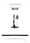
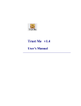
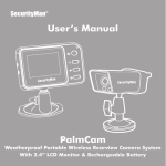
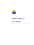
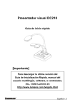
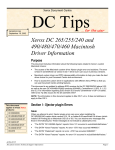
QUALITY ASSURANCE/QUALITY CONTROL DOCUMENTATION SERIES
TITLE
PROCUREMENT AND ACCEPTANCE TESTING PROCEDURES FOR
SCENE MONITORING EQUIPMENT
TYPE
STANDARD OPERATING PROCEDURE
NUMBER
4005
DATE
JANUARY 1994
AUTHORIZATIONS
TITLE
NAME
ORIGINATOR
Karen Fischer
PROJECT MANAGER
James H. Wagner
PROGRAM MANAGER
David L. Dietrich
QA MANAGER
Gloria S. Mercer
SIGNATURE
OTHER
REVISION HISTORY
REVISION
NO.
0.1
1.0
2.0
CHANGE
DESCRIPTION
DATE
Reviewed; no changes necessary.
January 1995
Minor format and equipment changes.
February 1996
Reviewed; no changes necessary.
February 1997
Reviewed; no changes necessary.
February 1998
Add SVHS video system references.
February 1999
Reviewed; no changes necessary.
February 2000
Reviewed; no changes necessary.
February 2001
Add digital camera systems/change originator.
August 2001
-- continued --
AUTHORIZATIONS
QUALITY ASSURANCE/QUALITY CONTROL DOCUMENTATION SERIES
TITLE
PROCUREMENT AND ACCEPTANCE TESTING PROCEDURES FOR
SCENE MONITORING EQUIPMENT
TYPE
STANDARD OPERATING PROCEDURE
NUMBER
4005
DATE
JANUARY 1994
AUTHORIZATIONS
TITLE
NAME
ORIGINATOR
Karen Fischer
PROJECT MANAGER
James H. Wagner
PROGRAM MANAGER
David L. Dietrich
QA MANAGER
Gloria S. Mercer
SIGNATURE
OTHER
REVISION HISTORY
REVISION
NO.
2.1
CHANGE
DESCRIPTION
DATE
Reviewed; no changes necessary.
August 2002
Add HRDC systems and equipment.
August 2003
AUTHORIZATIONS
Number 4005
Revision 2.1
Date AUG 2003
Page i of i
TABLE OF CONTENTS
Section
Page
1.0
PURPOSE AND APPLICABILITY
1
2.0
RESPONSIBILITIES
1
2.1 Project Manager
2.2 Data Coordinator
2.3 Field Specialist
2.4 Communications Technician
1
2
2
3
REQUIRED EQUIPMENT AND MATERIALS
3
3.1 Required Equipment and Materials for 35 mm or 8 mm Systems
3.2 Required Equipment and Materials for SVHS Video Systems
3.3 Required Equipment and Materials for Remote Digital Camera
Systems (RDCS)
3.4 Required Equipment and Materials for High-Resolution Digital
Camera Systems (HRDC)
3.5 Inventory
3
3
4
5
METHODS
6
4.1 Procurement
4.2 Acceptance Testing
4.3 Shipping
6
6
6
3.0
4.0
4
Number 4005
Revision 2.1
Date AUG 2003
Page 1 of 6
1.0
PURPOSE AND APPLICABILITY
This standard operating procedure (SOP) describes the steps for procurement and
acceptance testing of photographic and video equipment. This equipment is purchased for new
installations or as replacement equipment at scene monitoring sites. Acceptance testing is
performed to ensure that all systems are fully functional and operating within acceptable limits
when shipped to designated sites.
Purchasing, fabrication, and acceptance testing of a full system or individual components
of a system are addressed in the following technical instructions (TIs):
•
TI 4005-1000
Procurement and Acceptance Testing Procedures for 35 mm
Automatic Camera Systems
•
TI 4005-1001
Procurement and Acceptance Testing Procedures for 8 mm
Automatic Camera Systems
•
TI 4005-1050
Procurement and Acceptance Testing of SVHS Time-Lapse Video
Camera Systems for the Healy Clean Coal Project
•
TI 4005-1090
Procurement and Acceptance Testing Procedures for the Remote
High-Resolution Digital Camera System (RDCS-100)
•
TI 4005-1095
Procurement and Acceptance Testing Procedures for the HighResolution Digital Camera System (HRDC)
2.0
RESPONSIBILITIES
2.1
PROJECT MANAGER
The project manager shall:
•
Quote camera specifications, prices, and delivery times to purchasing agents.
•
Obtain information regarding specific equipment needed.
•
Obtain site information, contact person’s name, telephone number, shipping address,
and any other special instructions needed to ship equipment to a site.
•
Coordinate purchasing with the data coordinator.
•
Coordinate acceptance testing with the data coordinator and field specialist.
Number 4005
Revision 2.1
Date AUG 2003
Page 2 of 6
2.2
DATA COORDINATOR
The data coordinator shall:
2.3
•
Prepare equipment purchase orders as directed by the project manager and send the
orders to appropriate vendors.
•
Receive, label, log, and inventory all equipment.
•
Maintain inventory information in the equipment database.
•
Assemble photographic equipment and perform initial quality assurance checks.
•
Ship camera and lenses to a local factory-authorized repair facility for a full system
check.
•
Take test photographs with the camera to verify exposure and operation.
•
Assemble the photographic system (camera, cables, timer, batteries, controller,
Palmtop, etc.) and perform acceptance testing procedures.
•
Assemble the camera enclosures (including fabricating and installing camera tripods
and security plates).
•
Verify tripod placement and security of windows and doors in the camera enclosure.
•
Assemble a site operator’s manual and all necessary photographic monitoring
supplies.
•
Package and ship the photographic systems according to specifications.
FIELD SPECIALIST
The field specialist shall:
•
Assemble the video equipment (including camera, cables, monitor, and SVHS
recorder) and perform acceptance testing procedures.
•
Assemble the video enclosures (including heaters, fans, power systems, and any
required power systems, camera mounts, and security plates) and perform acceptance
testing procedures.
•
Assemble a site operator’s manual and all necessary time-lapse video monitoring
supplies.
•
Package and ship the video systems according to specifications.
Number 4005
Revision 2.1
Date AUG 2003
Page 3 of 6
2.4
COMMUNICATIONS TECHNICIAN
A trained and certified communications technician shall acceptance test any
communications system used in connection with a photographic or video monitoring system.
These communications systems may include a microwave transmitter/receiver system or other
specialized communications system.
3.0
REQUIRED EQUIPMENT AND MATERIALS
3.1
REQUIRED EQUIPMENT AND MATERIALS FOR 35 MM OR 8 MM SYSTEMS
Equipment and materials required to test a 35 mm or 8 mm photographic system include:
•
A camera
•
A lens (for 35 mm camera only)
•
A winding system (for 35 mm camera only)
•
A camera databack (for 35 mm camera only)
•
A UV filter (for 35 mm camera only)
•
Programmable timer and cables
•
Batteries
•
Film
•
A documentation chart
•
A Visibility Network Photo Log (35 mm camera only)
•
A Camera Test Form (8 mm camera only)
•
A tripod mount and mounting hardware
•
An environmentally-sealed and lockable enclosure
Equipment and materials required to test a camera system at a local factory-authorized
dealer also include a multi-plex camera tester.
3.2
REQUIRED EQUIPMENT AND MATERIALS FOR SVHS VIDEO SYSTEMS
Equipment and materials required to test an SVHS time-lapse video system include:
•
A high-resolution color video camera with lens
Number 4005
Revision 2.1
Date AUG 2003
Page 4 of 6
3.3
•
A programmable SVHS video recorder
•
A color video monitor
•
Power and signal cables
•
A cross-polarizing lens filter
•
A camera enclosure
•
SVHS videotapes
•
A voltmeter
•
An SVHS Time-Lapse Video System Test Log
REQUIRED EQUIPMENT AND MATERIALS FOR REMOTE DIGITAL
CAMERA SYSTEMS (RDCS)
Equipment and materials required to test a digital camera system include:
•
A voltmeter test platform
•
A high-resolution digital camera with zoom lens, integrated scripting, and batteries
installed
•
Camera cables
•
A PDA (Personal Digital Assistant) palm computer interface with batteries installed
and HotSync cable
•
A custom-designed controller
•
A battery-backed power system (AC or solar power)
•
A DC charge regulator
•
A tripod with quick release plate
•
Miscellaneous hardware and controller components
•
A high-resolution color video camera with lens
•
A camera enclosure
•
A Digital Camera System Test Log
Number 4005
Revision 2.1
Date AUG 2003
Page 5 of 6
3.4
REQUIRED EQUIPMENT AND MATERIALS FOR HIGH-RESOLUTION
DIGITAL CAMERA SYSTEMS (HRDC)
•
Digital multimeter
•
Standard tool kit
•
3-ring binders
•
Digital camera with batteries installed
•
4 AA replacement camera batteries
•
A camera enclosure with sun shield, thermal insulation, and thermostatically
controlled resistive heaters, fan, and window defroster
•
A camera power supply and thermostat circuitboard
•
A 50-foot to 100-foot 24 volt AC power cable
•
A 50-foot to 100-foot RS-232 signal cable or USB (Cat-5 Ethernet) cable
•
An 120 volt AC to 24 volt AC transformer or DC power supply
•
A 3-foot to 6-foot AC power cable
•
A personal computer with 20 to 40 gigabyte hard disk
•
An internal 56K modem and external 56K modem (optional)
•
An uninterruptible power supply (UPS)
•
Microsoft Windows operating software and ARS_DIGICAM and camera software
•
A lockable, environmental computer enclosure (optional)
•
Miscellaneous hardware
•
Optional equipment such as various mounting arms, posts, etc.
•
Site Operator’s Manual for High-Resolution Digital Camera Systems
Number 4005
Revision 2.1
Date AUG 2003
Page 6 of 6
3.5
INVENTORY
An up-to-date accounting of purchase and warranty information, location, and status of all
purchased equipment is maintained. Primary accounting is performed on an equipment database
developed by ARS. The database can be searched and sorted by fields to yield reports such as
equipment listings by site, equipment type, manufacturer, model number, serial number, property
number, purchase order number, date purchased, or a variety of additional search fields.
4.0
METHODS
This section includes the following three (3) subsections:
4.1 Procurement
4.2 Acceptance Testing
4.3 Shipping
4.1
PROCUREMENT
Purchase Orders (POs) for system components or fully integrated systems are generated
by the data coordinator and sent to the project manager for approval. Upon approval, the POs are
sent to the appropriate equipment vendors. Upon arrival at ARS, the equipment is cross-checked
against the PO and readied for acceptance testing. Complete descriptions of procurement
procedures are detailed in the system-specific TIs listed in Section 1.0 All components are
guaranteed.
4.2
ACCEPTANCE TESTING
Photographic or video equipment purchased from a manufacturer is subject to thorough
inspection and acceptance testing upon receipt at ARS. These inspections include individual
component and full system checks to verify that the equipment is operating within
manufacturer’s specifications. Enclosures are also prepared for monitoring component
installation, and operator’s manuals and supplies are prepared for shipment to the monitoring
sites.
ARS has a long, established relationship with local factory-authorized repair facilities.
These facilities provide prompt, thorough photographic testing and preventive maintenance and
repair services. Cameras that pass all tests are then tested as part of the integrated monitoring
system.
Complete descriptions for ARS testing and factory-authorized dealer testing are detailed
in the system-specific TIs listed in Section 1.0.
4.3
SHIPPING
Integrated photographic systems or individual components are packed for shipping
following successful testing. All shipments will be made by the most expedient, cost-effective
method. Packing slips containing item description, serial number, quantity, weight, and insurance
value for all shipments accompany each shipping container. A record of the shipment including a
copy of the packing slip is kept on file by the data coordinator.
QUALITY ASSURANCE/QUALITY CONTROL DOCUMENTATION SERIES
TITLE
PROCUREMENT AND ACCEPTANCE TESTING PROCEDURES FOR
35 MM AUTOMATIC CAMERA SYSTEMS
TYPE
TECHNICAL INSTRUCTION
NUMBER
4005-1000
DATE
NOVEMBER 1993
AUTHORIZATIONS
TITLE
NAME
ORIGINATOR
Karen K. Rosener
PROJECT MANAGER
James H. Wagner
PROGRAM MANAGER
David L. Dietrich
QA MANAGER
Gloria S. Mercer
SIGNATURE
OTHER
REVISION HISTORY
REVISION
NO.
0.1
CHANGE
DESCRIPTION
DATE
Reviewed; no changes necessary.
November 1994
Reviewed; no changes necessary.
November 1995
Minor format and equipment changes.
February 1996
Reviewed; no changes necessary.
February 1997
Reviewed; no changes necessary.
February 1998
Reviewed; no changes necessary.
February 1999
Reviewed; no changes necessary.
February 2000
Reviewed; no changes necessary.
February 2001
Reviewed; no changes necessary.
February 2002
AUTHORIZATIONS
Number 4005-1000
Revision 0.1
Date FEB 1996
Page i of i
TABLE OF CONTENTS
Section
Page
1.0
PURPOSE AND APPLICABILITY
1
2.0
RESPONSIBILITIES
1
2.1 Project Manager
2.2 Data Coordinator
1
1
REQUIRED EQUIPMENT AND MATERIALS
2
3.1
3.2
2
3
3.0
4.0
Camera System Testing
Inventory
METHODS
3
4.1 Procurement
3
4.1.1
4.1.2
Individual Components
Complete System
4.2 Acceptance Testing
4.2.1
4.2.2
4.2.3
4.3
3
4
4
Testing Cameras and Lenses
Testing of Integrated Monitoring System Including
Camera, Timers, Cables, and Batteries
Testing Enclosures
Shipping
4
5
5
5
LIST OF FIGURES
Figure
4-1
Page
Example Photographic Log for Camera Test Session
6
Number 4005-1000
Revision 0.1
Date FEB 1996
Page 1 of 6
1.0
PURPOSE AND APPLICABILITY
This technical instruction (TI) describes the steps for procurement and acceptance testing
of 35 mm photographic equipment. The primary purpose of acceptance testing is to ensure that
all systems are fully functional and operating within acceptable limits when shipped to designated
sites.
For the purpose of this TI, a full automatic 35 mm camera system consists of the following
components:
•
35 mm camera with winder and databack
•
Lens with UV filter
•
Programmable timer and cabling
•
Environmental enclosure with sunshield and internal locks
•
Quick-release camera mount
•
Documentation chart
•
Instruction manuals and example forms
•
Lens cleaning supplies
•
Batteries
•
Mounting post
2.0
RESPONSIBILITIES
2.1
PROJECT MANAGER
The project manager shall:
2.2
•
Quote camera specifications, prices, and delivery times to purchasing agents.
•
Obtain information regarding specific equipment needed.
•
Obtain site information, contact person’s name, telephone number, shipping address,
and any other special instructions needed to ship equipment to a site.
•
Receive customer purchase orders, direct the data coordinator to fill the order, and
further coordinate all information with the data coordinator.
DATA COORDINATOR
The data coordinator shall:
•
Prepare equipment purchase orders and send to appropriate vendors.
Number 4005-1000
Revision 0.1
Date FEB 1996
Page 2 of 6
•
Receive, label, log, and inventory all equipment.
•
Enter inventory information in the equipment database.
•
Assemble camera equipment and perform initial quality assurance checks.
•
Ship camera and lenses to a local factory-authorized repair facility for a full system
check.
•
Load the camera with film (when returned from the repair facility) and take test
photographs.
•
Assemble the photographic system (camera, cables, timer, and batteries) and perform
acceptance testing procedures.
•
Assemble the camera enclosures, including documentation charts, camera tripods,
security plates, standard setting and troubleshooting labels.
•
Verify tripod placement and security of windows and doors in the camera enclosure.
•
Assemble a site operator’s manual and all necessary photographic monitoring supplies.
•
Package and ship the photographic systems according to specifications.
3.0
REQUIRED EQUIPMENT AND MATERIALS
3.1
CAMERA SYSTEM TESTING
Equipment and materials required to test a camera system include:
•
Camera
•
Programmable timer
•
Lens
•
Winding system
•
Camera databack
•
UV filter
•
Power and camera cables
•
Batteries
•
Kodachrome 64 color slide film
•
Photographic log
•
Battery jumper bar
Number 4005-1000
Revision 0.1
Date FEB 1996
Page 3 of 6
3.2
•
Documentation chart
•
Environmentally-sealed and lockable enclosure
•
Tripod mount
•
Multi-plex camera tester (used at the factory-authorized repair facility)
INVENTORY
An up-to-date accounting of purchase and warranty information, location, and status of all
field and laboratory equipment will be maintained. Primary accounting will be performed on an
equipment database developed by ARS. The database can be searched and sorted by fields to
yield reports such as equipment listings by site, equipment type, manufacturer, model number,
serial number, property number, purchase order number, date purchased, or a variety of additional
search fields.
Monthly updates of the equipment database will be routinely performed by the data
coordinator. Purchase orders, repair records, and all other available sources of equipment status
will serve as documentation of equipment database entries.
All equipment not being used at a monitoring site will be stored in a secure location at
ARS. A detailed inventory of all items awaiting maintenance, testing, or future deployment will
be maintained at all times. Items uneconomical for repair will be salvaged for parts.
4.0
METHODS
This section includes the following three (3) subsections:
4.1 Procurement
4.2 Acceptance Testing
4.3 Shipping
4.1
PROCUREMENT
4.1.1 Individual Components
Purchase orders (POs) are generated by the data coordinator and sent to the project
manager for approval. Upon approval, the POs are sent to the appropriate equipment vendors.
Equipment is inventoried and readied for testing after receipt at ARS.
After receiving the individual components, fabrication of a complete system may be
required. Fabrication includes:
•
Assembly of camera enclosure
•
Assembly of integrated camera system for testing
•
Assembly of site operator’s manuals and operating supplies
Number 4005-1000
Revision 0.1
Date FEB 1996
Page 4 of 6
4.1.2 Complete System
Purchase orders (POs) are generated by the data coordinator and sent to the project
manager for approval. Upon approval, the POs are given to the instrument technician at ARS
Technologies, Inc. The equipment is inventoried when received by the data coordinator. All
35 mm automatic camera systems purchased from ARS Technologies, Inc. have undergone
thorough acceptance testing. All components are guaranteed.
4.2
ACCEPTANCE TESTING
Camera equipment purchased from a manufacturer will be subject to thorough inspection
and acceptance testing upon receipt at ARS. These inspections will include full system checks
and verifications to ensure that the equipment is operating properly.
4.2.1 Testing Cameras and Lenses
Upon receiving a camera and lens from a vendor, the following are performed:
•
The lens is attached to the camera.
•
Camera batteries are installed.
•
The camera is configured for remote operation (e.g., on a Canon EOS 630, the
standard grip would be removed and a remote jack grip installed).
•
Basic camera and lens functions are verified.
•
Warranty cards are completed.
•
Serial numbers are entered into the equipment database.
•
The camera and lens are both sent to a factory-authorized repair facility.
ARS has a long, established relationship with local factory-authorized repair facilities.
These facilities provide prompt, thorough photographic testing and preventive maintenance and
repair services, including ambient and cold testing of:
•
Current draw
•
Shutter speed and curtain travel time
•
Automatic exposure accuracy
•
Film transport
•
Diaphragm operation
•
Lens focus and disable soft focus mechanism
Number 4005-1000
Revision 0.1
Date FEB 1996
Page 5 of 6
When the camera, lens, and testing documentation are returned from the repair facility, the
camera is loaded with a 36-exposure roll of Kodachrome 64 color slide film and is taken to an
outdoor location. The following sequence of test photographs are taken:
•
Three photographs of the documentation chart, at apertures of 5.6, 8.0, and 11.0.
•
Three photographs of a vista, at ground to sky ratios of 70:30, 50:50, and 30:70.
Each set is taken at an aperture setting ranging from 4.0 to 11.0.
•
The lens is set to “auto” focus and the above procedures are repeated.
•
The last few frames on the roll are taken in several different directions at a ground to
sky ratio of 50:50.
The composition of each test photograph, test photograph settings, and the camera and
lens serial numbers are documented on a photographic log. An example of a completed
photographic log for a camera test session is provided as Figure 4-1. Film is then sent in for
processing. When test photographs are returned from processing, they are thoroughly reviewed
for exposure consistency, databack imprinting clarity, and focus. If problems are noted they are
returned to the repair facility for further evaluation or on the advice of the repair facility, returned
to the manufacturer. Cameras that pass all tests are then tested as part of the integrated
monitoring system.
4.2.2 Testing of Integrated Monitoring System Including Camera, Timers, Cables, and
Batteries
Timers and cables are tested by assembling the entire camera system, including timer,
cables, batteries, and camera. The timer is set to the current time, date, and alarm times. The
cables and camera are attached and the system is observed for two days to ensure all components
are functioning properly.
4.2.3 Testing Enclosures
The placement of the tripod mount is verified and adjusted if necessary. The window,
door lock, and latches are checked to ensure the enclosure is secure and completely weatherproof.
4.3
SHIPPING
Integrated camera systems or individual components are packed for shipping following
successful testing. All shipments will be made by the most expedient, cost-effective method,
usually by UPS Ground service. Packing slips containing item description, serial number,
quantity, weight, and insurance value for all shipments accompany each shipping container. A
record of the shipment including a copy of the packing slip is kept on file by the data coordinator.
Number 4005-1000
Revision 0.1
Date FEB 1996
Page 6 of 6
VISIBILITY NETWORK PHOTO LOG
Camera:___________________
Lens:_____________________
TEST ROLL
EXP. #
1
Doc Chart
2
TIME
APERTURE
5.6
NOTES
8.0
3
4
DATE
11.0
Manual
4.0
Ratios 70/30 50/50 30/70
5
6
7
5.6
8
9
10
8.0
11
12
13
11.0
14
15
16
Auto
4.0
17
18
19
5.6
20
21
22
8.0
23
24
25
11.0
26
27
28
Manual
8.0
50/50 ratio in 9 different directions
29
30
31
32
33
34
35
36
Figure 4-1. Example Photographic Log for Camera Test Session.
QUALITY ASSURANCE/QUALITY CONTROL DOCUMENTATION SERIES
TITLE
PROCUREMENT AND ACCEPTANCE TESTING PROCEDURES FOR
THE REMOTE HIGH-RESOLUTION DIGITAL CAMERA SYSTEM
(RDCS-100)
TYPE
TECHNICAL INSTRUCTION
NUMBER
4005-1090
DATE
AUGUST 2001
AUTHORIZATIONS
TITLE
NAME
ORIGINATOR
Karen Fischer
PROJECT MANAGER
James H. Wagner
PROGRAM MANAGER
David L. Dietrich
QA MANAGER
Gloria S. Mercer
SIGNATURE
OTHER
REVISION HISTORY
REVISION
NO.
CHANGE
DESCRIPTION
Reviewed; no changes necessary.
DATE
August 2002
AUTHORIZATIONS
Number 4005-1090
Revision 0
Date AUG 2001
Page i of i
TABLE OF CONTENTS
Section
Page
1.0
PURPOSE AND APPLICABILITY
1
2.0
RESPONSIBILITIES
1
2.1 Project Manager
2.2 Data Coordinator
1
1
REQUIRED EQUIPMENT AND MATERIALS
2
3.1 Testing Equipment
3.2 Shipping Equipment and Materials
3.3 Inventory
2
2
4
METHODS
4
4.1 Procurement
4.2 Acceptance Testing
4
4
3.0
4.0
4.2.1
4.2.2
4.2.3
4.3
Enclosure Preparation
Integrated Camera System Testing
Manuals and Supplies Preparation
Shipping
4
5
7
9
LIST OF FIGURES
Page
Figure
4-1
Digital Camera System Test Log
8
Number 4005-1090
Revision 0
Date AUG 2001
Page 1 of 9
1.0
PURPOSE AND APPLICABILITY
This technical instruction (TI) describes the steps for procurement and acceptance testing
of the Remote High-Resolution Digital Camera System (RDCS-100). The primary purpose of
acceptance testing is to ensure that all systems are fully functional and operating within acceptable
limits when shipped to designated sites. This TI is referenced in Standard Operating Procedure
(SOP) 4005, Procurement and Acceptance Testing Procedures for Scene Monitoring Equipment.
For the purpose of this TI, a full RDCS-100 camera system consists of the following
components:
•
A high-resolution digital camera with zoom lens and integrated scripting
•
A custom-designed controller
•
A PDA (Personal Digital Assistant) palm computer interface
•
A battery-backed power system (AC or solar power)
•
A lockable environmental enclosure
2.0
RESPONSIBILITIES
2.1
PROJECT MANAGER
The project manager shall:
2.2
•
Quote camera specifications, prices, and delivery times to purchasing agents.
•
Obtain information regarding specific equipment needed.
•
Obtain site information, contact person’s name, telephone number, shipping address,
and any other special instructions needed to ship equipment to a site.
•
Receive customer purchase orders, direct the data coordinator to fill the order, and
further coordinate all information with the data coordinator.
DATA COORDINATOR
The data coordinator shall:
•
Prepare equipment purchase orders and send to appropriate vendors.
•
Receive, label, log, and inventory all equipment.
•
Enter inventory information in the equipment database.
Number 4005-1090
Revision 0
Date AUG 2001
Page 2 of 9
•
Assemble camera equipment and perform initial quality assurance checks.
•
Take test photographs with the camera to verify exposure and operation.
•
Assemble the photographic system (camera, PDA, cables, etc.) and perform
acceptance testing procedures.
•
Assemble the camera enclosures, including camera tripods, security plates, etc.
•
Verify tripod placement and security of windows and doors in the camera enclosure.
•
Assemble a site operator’s manual and all necessary photographic monitoring supplies.
•
Package and ship the photographic systems according to specifications.
3.0
REQUIRED EQUIPMENT AND MATERIALS
3.1
TESTING EQUIPMENT
•
3.2
Voltmeter test platform
SHIPPING EQUIPMENT AND MATERIALS
•
Kodak digital camera with batteries installed
•
Camera cables
•
A custom-designed controller
•
A PDA (Personal Digital Assistant) palm computer interface with batteries installed
and HotSync cable
•
A battery-backed power system (AC or solar power)
•
Gel cell rechargeable battery
•
DC charge regulator
•
Tripod with quick release plate
•
A lockable environmental enclosure
•
Miscellaneous hardware and controller components
•
Mounting post
Number 4005-1090
Revision 0
Date AUG 2001
Page 3 of 9
•
Site Operator’s Manual for Remote High-Resolution Digital Camera Systems,
containing:
-
SOP 4120, Automatic Camera System Maintenance
TI 4120-3800, Routine Site Operator Maintenance Procedures for the Remote
High-Resolution Digital Camera System (RDCS-100)
TI 4120-3900, Troubleshooting and Emergency Maintenance Procedures for the
Remote High-Resolution Digital Camera System (RDCS-100)
User’s Manual
Site configuration settings
Visibility Monitoring Status/Assessment Sheets
Manufacturer’s manuals (PDA, Kodak camera)
Miscellaneous supplies
•
Equipment letter with site-specific serial numbers
•
Memory card pouches with labels
•
Mailing envelopes with FedEx return airbill (2)
•
128 MB memory cards (2)
•
Backup batteries:
- (4) AA lithium camera batteries
- (2) AAA alkaline PDA batteries
•
Enclosure keys (2)
•
Mounting hardware
•
Camera lens cleaning tissue (1 packet)
•
Lens cleaning fluid (1 bottle)
•
Desiccant (2 packages)
•
Extra sheet metal plugs (2 sizes)
•
Packing supplies, including:
- 18” x 18” x 18” dw box
- Packing material
- Cardboard for both sides of enclosure window
- PVC tubing cut to size for solenoid protection
- Tie for power cord
Number 4005-1090
Revision 0
Date AUG 2001
Page 4 of 9
3.3
INVENTORY
An up-to-date accounting of purchase and warranty information, location, and status of all
field and laboratory equipment will be maintained. Primary accounting will be performed on an
equipment database developed by ARS. The database can be searched and sorted by fields to yield
reports such as equipment listings by site, equipment type, manufacturer, model number, serial
number, property number, purchase order number, date purchased, or a variety of additional
search fields.
Monthly updates of the equipment database will be routinely performed by the data
coordinator. Purchase orders, repair records, and all other available sources of equipment status
will serve as documentation of equipment database entries.
All equipment not being used at a monitoring site will be stored in a secure location at
ARS. A detailed inventory of all items awaiting maintenance, testing, or future deployment will be
maintained at all times. Items uneconomical for repair will be salvaged for parts.
4.0
METHODS
This section includes three (3) major subsections:
4.1 Procurement
4.2 Acceptance Testing
4.3 Shipping
4.1
PROCUREMENT
Purchase orders (POs) are generated by the data coordinator and sent to the project
manager for approval. Upon approval, the POs are sent to the appropriate equipment vendors.
Equipment is inventoried and readied for testing after receipt at ARS. All components are
guaranteed.
After receiving the individual components, fabrication of a complete system may be
required. Fabrication includes:
4.2
•
Assembly of camera enclosure
•
Assembly of integrated camera system for testing
•
Assembly of site operator’s manuals and operating supplies
ACCEPTANCE TESTING
4.2.1 Enclosure Preparation
The equipment enclosure is prepared for installation and use at a site as follows:
Number 4005-1090
Revision 0
Date AUG 2001
Page 5 of 9
DRILL HOLES
Holes are drilled in various parts of the shelter to allow for
mounting of equipment and cabling to pass through.
POSITION SHELF
Affix the shelf inside the enclosure to the proper position.
PREPARE PORTAL
Send the portal template to the enclosure manufacturer for
cutting.
Drill holes in the vandal plate.
Attach glass to portal window with silicone.
Attach window defroster kit.
PREPARE INSTRUCTIONS Attach plastic pocket to inside of enclosure door.
Place User’s Manual in pocket.
PREPARE ENCLOSURE
Clean out metal shavings from enclosure and prepare for
equipment installation.
Line the bottom of the enclosure with insulation.
Install a heating pad (if needed).
Affix battery cable.
Plug unused inlet holes.
Silicone around exterior screws and hood.
4.2.2 Integrated Camera System Testing
Camera equipment purchased from a manufacturer will be subject to a thorough inspection
and acceptance testing upon receipt at ARS. These inspections will include full system checks and
verifications to ensure that the equipment operates properly.
The electronic technician is provided with all needed equipment for testing. Individual
components are tested first, then the system is assembled and tested as a unit. Component and
system test procedures are:
KODAK DIGITAL
CAMERA
Program the correct date and time into the camera.
Program the site’s abbreviation (if known).
Turn the camera’s flash feature off.
Number 4005-1090
Revision 0
Date AUG 2001
Page 6 of 9
PERSONAL DIGITAL
ASSISTANT (PDA)
Program the unit with PalmCam software.
Test PDA programming and HotSync operation:
• Open the palm desktop program on a PC.
• Click on the HotSync icon on the taskbar and make sure
“local” is checked on the menu.
• In the palm desktop, select the user in the top-right corner
as FSCAM.
• Connect the PDA to the HotSync cable (connected to the
PC). Set the date and time.
• At the palm desktop, click the Install button at the
bottom-left of the menu.
• Choose the user FSCAM in the install toolbox.
• Click the Add button at the right side in the drop-down
menu. Go to
programming.
G:\project\fsvis\digicam\rdcs
palm
• Highlight all three files (fscamera.prc, mathlib.prc, and
nsbruntime.prc). Click Open.
• The program will go back to the install toolbox where the
three files are. Click Done.
• A message box will appear informing that the files will
transfer the next time a HotSync operation is performed.
• Press the HotSync button on the cable.
• The palm menu will inform you when the transfer is
complete. Verify that PalmCam appears in the main menu
on the PDA. You may need to click All in the right-corner
to view all icons in the main menu.
Refer to the PDA manual for more detailed instructions.
Program the correct date and time into the PDA.
Enter basic site information (if known) (zoom, site abbreviation,
etc.).
Number 4005-1090
Revision 0
Date AUG 2001
Page 7 of 9
CONTROLLER
Program the controller with ARS software.
Verify that the green LED is flashing on the controller, signifying
the unit is functioning correctly.
TEST POWER SYSTEM
Turn on the voltmeter test platform meters and connect both blue
cables. Check the voltage (on the left side of the platform) of the
battery charger. The voltage should be ~13-14.0. Push the button
on the platform to test the 12v battery only.
Read the current in miliamps on the right side of the platform.
Have the switch on “test.” When the battery is topped off then it
will read close to “0.”
To test a solar panel, use the right side of the voltage test
platform. Plug in the blue cable and check the current. If the
battery is down to 12-13 volts, and not showing much current,
the battery will deplete.
When the battery button is pushed, the charge voltage needs to be
higher than the battery voltage or it sets up reverse current and
depletes the battery.
TEST SYSTEM AS A UNIT
Run the complete, assembled system over a period of time as it
will be run at the monitoring site. Use AC or solar power as
required. Test the scripting programs and proper memory card
storage of the Image.dat file, battery voltage, image count, etc.
Before testing the system, note the initial battery voltage,
temperature, and image frequency. Set the controller date and
time on the system log (refer to Figure 4-1).
4.2.3 Manuals and Supplies Preparation
All operator manuals and supplies are gathered and verified for shipment to a monitoring
site. The Site Operator’s Manual for Remote High-Resolution Digital Camera Systems contains:
•
SOP 4120, Automatic Camera System Maintenance
•
TI 4120-3800, Routine Site Operator Maintenance Procedures for the Remote HighResolution Digital Camera System (RDCS-100)
•
TI 4120-3900, Troubleshooting and Emergency Maintenance Procedures for the
Remote High-Resolution Digital Camera System (RDCS-100)
•
User’s Manual
Number 4005-1090
Revision 0
Date AUG 2001
Page 8 of 9
•
Site configuration settings
•
Visibility Monitoring Status/Assessment Sheets
•
Manufacturer’s manuals (PDA, Kodak camera)
•
Miscellaneous supplies
All other supplies are small (e.g., batteries, lens cleaning fluid) and are placed in a plastic bag
inside the enclosure. See Section 3.2 for a complete list of monitoring supplies.
4.3
SHIPPING
Integrated camera systems or individual components are packed for shipping following
successful testing. All shipments will be made by the most expedient, cost-effective method,
usually by UPS Ground service. Packing slips containing item description, serial number, quantity,
weight, and insurance value for all shipments accompany each shipping container. A record of the
shipment including a copy of the packing slip is kept on file by the data coordinator.
All electronic components are packed separately to prepare for shipping to a monitoring
site. All power cables to the camera, PDA, and gel cell battery are detached and wrapped
separately. The solenoid is protected with PVC tubing for shipment.
All items are packed inside the enclosure box, including the site operator’s manual and bag
of miscellaneous monitoring supplies. The enclosure is packed in a heavy box with material
packed tightly around it. The mounting post is shipped separately from the enclosure.
Digital Camera System Test Log
System Model:
Proposed Client/Site Abbr.
Enclosure ID#
Controller Board Series #:
Camera Model:
Palm Model:
ID#:
AC/Solar Testing:
Average Operating Conditions:
Date
Type of Image
Auto/Forced
Time
Battery
Voltage
Temp
Reading
#
Exposures
Card Exchange
(Attach .Dat file)
Number 4005-1090
Revision 0
Date AUG 2001
Page 9 of 9
Figure 4-1. Digital Camera System Test Log.
Other Comments:
QUALITY ASSURANCE/QUALITY CONTROL DOCUMENTATION SERIES
TITLE
PROCUREMENT AND TESTING PROCEDURES FOR THE HIGHRESOLUTION DIGITAL CAMERA SYSTEM (HRDC)
TYPE
TECHNICAL INSTRUCTION
NUMBER
4005-1095
DATE
JULY 2003
AUTHORIZATIONS
TITLE
NAME
ORIGINATOR
Jeff Ogburn
PROJECT MANAGER
Scott Cismoski
PROGRAM MANAGER
David L. Dietrich
QA MANAGER
Gloria S. Mercer
SIGNATURE
OTHER
REVISION HISTORY
REVISION
NO.
CHANGE
DESCRIPTION
DATE
AUTHORIZATIONS
Number 4005-1095
Revision 0
Date JUL 2003
Page i of i
TABLE OF CONTENTS
Page
Section
1.0
PURPOSE AND APPLICABILITY
1
2.0
RESPONSIBILITIES
1
2.1 Project Manager
2.2 Data Coordinator
1
2
REQUIRED EQUIPMENT AND MATERIALS
2
3.1 Fabrication and Testing Equipment and Materials
3.2 Shipping Equipment and Materials
3.3 Inventory
2
2
3
METHODS
4
4.1 Procurement
4.2 Acceptance Testing
4
4
3.0
4.0
4.2.1
4.2.2
4.2.3
4.2.4
4.3
Camera Subsystem Preparation
Power Supply Subsystem Preparation
Computer Subsystem Preparation
4
7
7
4.2.3.1
4.2.3.2
7
7
Computer Hardware Preparation
Computer Software Preparation
Manuals and Supplies Preparation
Shipping
9
10
LIST OF FIGURES
Figure
Page
4-1
Mode Dial Location for Kodak DC265 and Olympus C2100
5
4-2
Component Location Inside the Pelco Camera Enclosure
(Serial and USB Connections)
6
Number 4005-1095
Revision 0
Date JUL 2003
Page 1 of 10
1.0
PURPOSE AND APPLICABILITY
This technical instruction (TI) describes the steps for procurement and acceptance testing
of the High-Resolution Digital Camera System (HRDC). The primary purpose of acceptance
testing is to ensure that all systems are fully functional and operating within acceptable limits
when shipped to designated sites. This TI is referenced in Standard Operating Procedure (SOP)
4005, Procurement and Acceptance Testing Procedures for Scene Monitoring Equipment.
For the purpose of this TI, a full HRDC camera system consists of the following
components:
•
A high-resolution digital camera with zoom lens
•
A camera enclosure with:
- A camera power circuitboard
- A thermostat circuitboard
- A 120 volt AC to 24 volt AC transformer or DC power supply
•
A personal computer with 20 to 40 gigabyte hard disk and modem
•
An uninterruptible power supply (UPS)
•
Microsoft Windows operating software and ARS_DIGICAM software
•
A lockable, environmental computer enclosure (optional)
System configurations may vary depending upon availability of power or severe weather
conditions at site locations. Alternative components may include battery power supplies, solar
panels, a second modem, satellite equipment, etc.
The digital camera system is designed to acquire images from a digital camera subsystem
and upload the images to an FTP site on the Internet for subsequent display on a Web page. In
addition, the user can install remote access software such as pcAnywhere (with modems or a
LAN connection) to allow access to the PC from another PC for image file acquisition and/or
system monitoring and configuration.
2.0
RESPONSIBILITIES
2.1
PROJECT MANAGER
The project manager shall:
•
Quote camera specifications, prices, and delivery times to purchasing agents.
•
Obtain information regarding specific equipment needed.
•
Obtain site information, contact person’s name, telephone number, shipping address,
and any other special instructions needed to ship equipment to a site.
Number 4005-1095
Revision 0
Date JUL 2003
Page 2 of 10
•
2.2
Receive customer purchase orders, direct the data coordinator to complete the order,
and further coordinate all information with the data coordinator.
DATA COORDINATOR
The data coordinator shall:
•
Prepare equipment purchase orders and send to appropriate vendors.
•
Receive, label, log, and inventory all equipment.
•
Enter inventory information in the equipment database.
•
Assemble camera equipment and perform initial quality assurance checks.
•
Take test images with the camera to verify exposure and operation.
•
Assemble the system (camera, cables, computer, etc.) and perform acceptance testing
procedures.
•
Assemble the camera enclosure, including circuitboard, power supply, etc.
•
Assemble a site operator’s manual and all necessary monitoring supplies.
•
Package and ship the systems according to specifications.
3.0
REQUIRED EQUIPMENT AND MATERIALS
3.1
FABRICATION AND TESTING EQUIPMENT AND MATERIALS
3.2
•
Digital multimeter
•
Standard tool kit with adjustable crescent wrench, channel-lock pliers, standard
combination wrench set, screwdrivers (flat-head and Phillips-head), wire snips,
needle-nose pliers, regular pliers, wire ties, and electrical tape
•
3-ring binders
SHIPPING EQUIPMENT AND MATERIALS
•
Digital camera with batteries installed
•
4 AA replacement camera batteries
•
A camera enclosure with sun shield, thermal insulation, and thermostatically
controlled resistive heaters, fan, and window defroster
Number 4005-1095
Revision 0
Date JUL 2003
Page 3 of 10
3.3
•
A camera power supply and thermostat circuitboard
•
A 50-foot to 100-foot 24 volt AC power cable
•
A 50-foot to 100-foot RS-232 signal cable or USB (Cat-5 Ethernet) cable
•
An 120 volt AC to 24 volt AC transformer or DC power supply
•
A 3-foot to 6-foot AC power cable
•
A personal computer with 20 to 40 gigabyte hard disk
•
An internal 56K modem and external 56K modem (optional)
•
An uninterruptible power supply (UPS)
•
Microsoft Windows operating software and ARS_DIGICAM and camera software
•
A lockable, environmental computer enclosure (optional)
•
Miscellaneous hardware
•
Optional equipment such as various mounting arms, posts, etc.
•
Site Operator’s Manual for High-Resolution Digital Camera Systems, containing:
- SOP 4120, Automatic Camera System Maintenance
- TI 4120-3850, Routine Site Operator Maintenance Procedures for the
High-Resolution Digital Camera System (HRDC)
- TI 4120-3950, Troubleshooting and Emergency Maintenance Procedures for the
High-Resolution Digital Camera System (HRDC
- TI 4610-5040, Digital Camera Image and Data Archives
- High-Resolution Digital Camera System User’s Manual
- Site configuration and settings
- Manufacturer’s manuals
INVENTORY
An up-to-date accounting of purchase and warranty information, location, and status of all
field and laboratory equipment will be maintained. Primary accounting will be performed on an
equipment database developed by ARS. The database can be searched and sorted by fields to
yield reports such as equipment listings by site, equipment type, manufacturer, model number,
serial number, property number, purchase order number, date purchased, or a variety of
additional search fields.
Monthly updates of the equipment database will be routinely performed by the data
coordinator. Purchase orders, repair records, and all other available sources of equipment status
will serve as documentation of equipment database entries.
Number 4005-1095
Revision 0
Date JUL 2003
Page 4 of 10
All equipment not being used at a monitoring site will be stored in a secure location at
ARS. A detailed inventory of all items awaiting maintenance, testing, or future deployment will
be maintained at all times. Items uneconomical for repair will be salvaged for parts.
4.0
METHODS
This section includes three (3) major subsections:
4.1 Procurement
4.2 Acceptance Testing
4.3 Shipping
4.1
PROCUREMENT
Purchase orders (POs) are generated by the data coordinator and sent to the project
manager for approval. Upon approval, the POs are sent to the appropriate equipment vendors.
Equipment is inventoried and readied for testing after receipt at ARS. All components are
guaranteed.
After receiving the individual components, fabrication of a complete system may be
required. Fabrication includes:
4.2
•
Assembly of the camera enclosure components
•
Assembly of the power supply
•
Assembly of the computer hardware
•
Assembly of site operator’s manuals and operating supplies
ACCEPTANCE TESTING
The high-resolution digital camera system contains three subsystems, the camera
subsystem, the power supply subsystem, and the computer subsystem. Acceptance testing
procedures for each subsystem are detailed in the following sections.
4.2.1
Camera Subsystem Preparation
Camera equipment purchased from a manufacturer will be subject to thorough inspection
and acceptance testing upon receipt at ARS. These inspections will include full system checks
and verifications to ensure that the equipment operates properly.
The camera subsystem does not currently include mounting hardware pending
information on where the unit will be installed. Two threaded mounting holes in the base of the
enclosure allow for attaching a standard Pelco product or other appropriate mount. The camera
enclosure and interior components is prepared for installation and use at a site as follows:
Number 4005-1095
Revision 0
Date JUL 2003
Page 5 of 10
INSERT BATTERIES
Inert the 4 AA batteries into the camera. The batteries keep the
camera operational in the event of AC power failure.
SET CAMERA MODE
The camera must be ON at all times. If the camera turns off due
to lack of power or prolonged periods without communication
with the PC, the camera will need to be turned on manually.
For the Kodak DC265 or 290 camera, set the camera mode dial
to CONNECT. For the Olympus C2100 or C-730 camera, set the
camera mode dial to “P” to enable communication with the PC.
Refer to Figure 4-1.
Figure 4-1. Mode Dial Location for Kodak DC265 and
Olympus C2100
ASSEMBLE WIRING
Assemble all wiring in the camera enclosure and PC enclosure.
ATTACH POWER SUPPLY
Attach the 24 volt power supply and turn it on. The ventilation
fan may come on. Refer to Figure 4-2 for component location
inside the camera enclosure.
TEST SYSTEM AS A UNIT
Run the complete, assembled system overnight as it will be run
at the monitoring site. This will ensure that the wires have been
“pinned” correctly, the PC software and modems have been
configured correctly, and that the camera is working properly.
Typical problems arise when wiring is not seated or pinned
correctly, the modem is dialing the wrong telephone number, or
if the camera is not setup correctly. Usually, the system is tested
by having it dial a local ISP to upload to an FTP site with a
typical 15-minute interval between images. Also, if the system
has pcAnywhere software, an attempt is made to dial into the PC.
The ARS_DIGICAM.INI file is re-configured for site-specific
information once testing is complete.
Number 4005-1095
Revision 0
Date JUL 2003
Page 6 of 10
Red light on means
incoming power is
good.
Camera power
supply. Converts 24
VAC to DC.
Green light on
means outgoing
camera power is
good. Dim light
could mean failure.
6.5v DC.
Thermostat to
heaters and window
defrost.
Serial cable coming
from PC connects
here. Pins 8-7-6-5
color must be in the
same order as on
the serial cable off
Pelco board. Color
as are red, white,
black, and green.
24v AC Pelco board
feeds to camera
power supply,
defrosters, and fan
B
Camera data
cable meets
Pelco board then
goes to serial
connection at B.
USB cable.
USB booster,
remote end
Cat-5 cable
Figure 4-2. Component Location Inside the Pelco Camera Enclosure (Serial and USB
Connections).
Number 4005-1095
Revision 0
Date JUL 2003
Page 7 of 10
4.2.2
Power Supply Subsystem Preparation
The camera subsystem is powered by a 24 volt AC or DC power supply, which requires
110 volt AC power. The power supply is usually housed indoors with the computer or in an
outdoor computer enclosure, and includes at least 50 feet of cable to the camera enclosure. Power
switches on the AC power supplies include an integrated circuit breaker. The power is ON when
the switch is UP.
4.2.3
Computer Subsystem Preparation
Both hardware and software must be prepared for the digital camera system’s computer.
4.2.3.1 Computer Hardware Preparation
The PC interface to the camera subsystem is via an RS-232 serial port or USB port. The
PC is equipped with the following ports:
COM1 (9-pin, built-in)
NECCARD
External modem (optional)
2 PCMIA slots
2 USB ports
The port assignments listed above are defined in the configuration
(ARS_DIGICAM.INI). Detailed information on this file is included in Section 4.2.3.2.
file
The PC and camera should be plugged into the uninterruptible power supply to ensure the
PC continues to operate in the event of short duration power failures. If the PC has a separate
monitor, the monitor is not plugged into the UPS.
4.2.3.2 Computer Software Preparation
Software preparation includes both the ARS_DIGICAM software and Internet
connectivity software. The digital camera system includes custom ARS_DIGICAM software to
perform the following functions:
•
Control the digital camera
•
Acquire JPG images from the camera
•
Package the images and associated image information into ZIP files
•
Establish a dial-up connection to the Internet
•
Establish a connection to an FTP site on the Internet
•
Transfer JPG or ZIP files to the FTP site
•
Accept data from an onsite datalogger for inclusion with the image upload
The software handles all functions automatically and allows the user to manually snap
and/or upload images from the camera subsystem. The software configuration is specified in the
ARS_DIGICAM.INI file, described below.
Number 4005-1095
Revision 0
Date JUL 2003
Page 8 of 10
The ARS_DIGICAM software consists of three to five tabbed panes of information:
•
Log
•
Camera #1
•
Status (newer systems only)
•
Setup
•
Data (if collecting associated visibility or air quality data)
More information regarding these tabbed panes can be found in TI 4120-3850, Routine
Site Operator Maintenance Procedures for the High-Resolution Digital Camera System (HRDC)
and TI 4120-3950, Troubleshooting and Emergency Maintenance Procedures for the HighResolution Digital Camera System (HRDC).
The Log tab is a text listing of the system’s operations and allows the user to read the
status of the system and troubleshoot functions. The Camera #1 tab allows the user to view the
most recent image acquired and take manual images to test the camera subsystem. The Setup tab,
on newer systems, allows the user to change system settings. The Data tab is used in conjunction
with collection of associated air quality or visibility data.
The Status tab provides the most information on the system’s operation. When the
Automatic Operation checkbox is checked the software will acquire and upload images
automatically according to the schedule defined in the ARS_DIGICAM.INI file. When the
checkbox is not checked, the Manual menu item is available and enables several operations for
taking pictures, uploading files, and changing the configuration.
When ARS_DIGICAM is invoked, it reads the ARS_DIGICAM.INI file and attempts to
connect to and configure the camera using the settings in the file. If the camera is off the software
will indicate the initialization failed. If that occurs, check the camera and cables, and restart the
software. Note: The camera must be on first before the computer is turned on.
IMPORTANT: If an error message occurs indicating “FATAL ERROR INITIALIZING
PROGRAM” appears, there is an incorrect or missing entry in the INI file. Contact ARS for
assistance.
After successful initialization, the Automatic Operation box will be checked and the
software will wait for the specified image acquisition time. At the correct time, the software will
perform the following actions:
•
Connect to the camera, snap an image, and download it to the PC
•
Read the current CR10 data file for most recent data collected by the PC208W
software from the CR10 datalogger
•
Call the ESC8816 datalogger for the most recent data
Number 4005-1095
Revision 0
Date JUL 2003
Page 9 of 10
•
Add the CR10 and ESC8816 data to the ZIP file
•
Add the JPG image file to a ZIP file
•
The ZIP file is uploaded to the FTP site
The upload process occurs when the upload enable box is checked. The process is:
•
The software will attempt to establish a dial-up Internet connection via an ISP.
•
A connection to the FTP site defined in the INI file will be established.
•
The file(s) will be transferred in 4096 byte blocks.
•
The FTP connection will be terminated.
•
The Dial-up connection will be terminated.
The JPG and ZIP files, program files, and error/log files are arranged in the following
directory structure:
C:\ARS_DIGICAM
\DATA
\RETRY
\UPLOAD
\ERRORS
ARS_DIGICAM.EXE
ARS_DIGICAM.INI
*.JPG, *.ZIP
*.JPG, *.ZIP
*.JPG, *.ZIP
*.ERR
The RETRY directory will contain files that should have been uploaded but could not be.
ARS_DIGICAM will attempt to upload the files at the time specified in the INI file.
The ARS_DIGICAM software needs to connect to an FTP site on the Internet to upload
images to Web page display. The software uses the standard Windows dial-up networking
system. If a dedicated Internet connection is available (i.e., DSL, cable modem, etc.), the
software will use it instead of establishing a dial-up connection.
Users can configure the .INI file to change camera settings or connection settings. The
INI file also contains information about the FTP site that will serve as the image upload
destination. Contact ARS for assistance in changing this file.
4.2.4
Manuals and Supplies Preparation
All operator manuals and supplies are gathered and verified for shipment to a
monitoring site. The Site Operator’s Manual for High-Resolution Digital Camera Systems
contains:
Number 4005-1095
Revision 0
Date JUL 2003
Page 10 of 10
4.3
•
SOP 4120, Automatic Camera System Maintenance
•
TI 4120-3850, Routine Site Operator Maintenance Procedures for the HighResolution Digital Camera System (HRDC)
•
TI 4120-3950, Troubleshooting and Emergency Maintenance Procedures for the
High-Resolution Digital Camera System (HRDC
•
TI 4610-5040, Digital Camera Image and Data Archives
•
High-Resolution Digital Camera System User’s Manual
•
Site configuration and settings
•
Manufacturer’s manuals
SHIPPING
Integrated camera systems or individual components are packed for shipping following
successful testing. All shipments will be made by the most expedient, cost-effective method,
usually by FedEx or UPS. Packing slips containing item description, serial number, quantity,
weight, and insurance value for all shipments accompany each shipping container. A record of
the shipment including a copy of the packing slip is kept on file by the data coordinator.
All items are packed inside the enclosure box, including the site operator’s manual and
bag of miscellaneous monitoring supplies. The enclosure is packed in a heavy box with material
packed tightly around it. The mounting post (if used) is shipped separately from the enclosure.