1
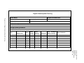
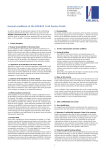
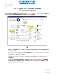
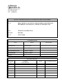
QUALITY ASSURANCE/QUALITY CONTROL DOCUMENTATION SERIES
TITLE
PROCUREMENT AND TESTING PROCEDURES FOR THE REMOTE
HIGH-RESOLUTION DIGITAL CAMERA SYSTEM (RDCS-100)
TYPE
TECHNICAL INSTRUCTION
NUMBER
4005-1090
DATE
AUGUST 2001
AUTHORIZATIONS
TITLE
NAME
ORIGINATOR
Karen Fischer
PROJECT MANAGER
James H. Wagner
PROGRAM MANAGER
David L. Dietrich
QA MANAGER
Gloria S. Mercer
SIGNATURE
OTHER
REVISION HISTORY
REVISION
NO.
CHANGE
DESCRIPTION
DATE
AUTHORIZATIONS
Number 4005-1090
Revision 0
Date AUG 2001
Page i of i
TABLE OF CONTENTS
Section
Page
1.0
PURPOSE AND APPLICABILITY
1
2.0
RESPONSIBILITIES
1
2.1
2.2
1
1
3.0
4.0
Project Manager
Data Coordinator
REQUIRED EQUIPMENT AND MATERIALS
2
3.1
3.2
3.3
2
2
4
Testing Equipment
Shipping Equipment and Materials
Inventory
METHODS
4
4.1
4.2
Procurement
Acceptance Testing
4
4
4.2.1 Enclosure Preparation
4.2.2 Integrated Camera System Testing
4.2.3 Manuals and Supplies Preparation
4
5
7
Shipping
9
4.3
LIST OF FIGURES
Figure
4-1
Digital Camera System Test Log
Page
8
Number 4005-1090
Revision 0
Date AUG 2001
Page 1 of 9
1.0
PURPOSE AND APPLICABILITY
This technical instruction (TI) describes the steps for procurement and acceptance testing
of the Remote High-Resolution Digital Camera System (RDCS-100). The primary purpose of
acceptance testing is to ensure that all systems are fully functional and operating within acceptable
limits when shipped to designated sites. This TI is referenced in Standard Operating Procedure
(SOP) 4005, Procurement and Acceptance Testing Procedures for Scene Monitoring Equipment.
For the purpose of this TI, a full RDCS-100 camera system consists of the following
components:
•
A high-resolution digital camera with zoom lens and integrated scripting
•
A custom-designed controller
•
A PDA (Personal Digital Assistant) palm computer interface
•
A battery-backed power system (AC or solar power)
•
A lockable environmental enclosure
2.0
RESPONSIBILITIES
2.1
PROJECT MANAGER
The project manager shall:
2.2
•
Quote camera specifications, prices, and delivery times to purchasing agents.
•
Obtain information regarding specific equipment needed.
•
Obtain site information, contact person’s name, telephone number, shipping address,
and any other special instructions needed to ship equipment to a site.
•
Receive customer purchase orders, direct the data coordinator to fill the order, and
further coordinate all information with the data coordinator.
DATA COORDINATOR
The data coordinator shall:
•
Prepare equipment purchase orders and send to appropriate vendors.
•
Receive, label, log, and inventory all equipment.
•
Enter inventory information in the equipment database.
Number 4005-1090
Revision 0
Date AUG 2001
Page 2 of 9
•
Assemble camera equipment and perform initial quality assurance checks.
•
Take test photographs with the camera to verify exposure and operation.
•
Assemble the photographic system (camera, PDA, cables, etc.) and perform
acceptance testing procedures.
•
Assemble the camera enclosures, including camera tripods, security plates, etc.
•
Verify tripod placement and security of windows and doors in the camera enclosure.
•
Assemble a site operator’s manual and all necessary photographic monitoring supplies.
•
Package and ship the photographic systems according to specifications.
3.0
REQUIRED EQUIPMENT AND MATERIALS
3.1
TESTING EQUIPMENT
•
3.2
Voltmeter test platform
SHIPPING EQUIPMENT AND MATERIALS
•
Kodak digital camera with batteries installed
•
Camera cables
•
A custom-designed controller
•
A PDA (Personal Digital Assistant) palm computer interface with batteries installed
and HotSync cable
•
A battery-backed power system (AC or solar power)
•
Gel cell rechargeable battery
•
DC charge regulator
•
Tripod with quick release plate
•
A lockable environmental enclosure
•
Miscellaneous hardware and controller components
•
Mounting post
Number 4005-1090
Revision 0
Date AUG 2001
Page 3 of 9
•
Site Operator’s Manual for Remote High-Resolution Digital Camera Systems,
containing:
-
SOP 4120, Automatic Camera System Maintenance
TI 4120-3800, Routine Site Operator Maintenance Procedures for the Remote
High-Resolution Digital Camera System (RDCS-100)
TI 4120-3900, Troubleshooting and Emergency Maintenance Procedures for the
Remote High-Resolution Digital Camera System (RDCS-100)
User’s Manual
Site configuration settings
Visibility Monitoring Status/Assessment Sheets
Manufacturer’s manuals (PDA, Kodak camera)
Miscellaneous supplies
•
Equipment letter with site-specific serial numbers
•
Memory card pouches with labels
•
Mailing envelopes with FedEx return airbill (2)
•
128 MB memory cards (2)
•
Backup batteries:
- (4) AA lithium camera batteries
- (2) AAA alkaline PDA batteries
•
Enclosure keys (2)
•
Mounting hardware
•
Camera lens cleaning tissue (1 packet)
•
Lens cleaning fluid (1 bottle)
•
Desiccant (2 packages)
•
Extra sheet metal plugs (2 sizes)
•
Packing supplies, including:
- 18” x 18” x 18” dw box
- Packing material
- Cardboard for both sides of enclosure window
- PVC tubing cut to size for solenoid protection
- Tie for power cord
Number 4005-1090
Revision 0
Date AUG 2001
Page 4 of 9
3.3
INVENTORY
An up-to-date accounting of purchase and warranty information, location, and status of all
field and laboratory equipment will be maintained. Primary accounting will be performed on an
equipment database developed by ARS. The database can be searched and sorted by fields to yield
reports such as equipment listings by site, equipment type, manufacturer, model number, serial
number, property number, purchase order number, date purchased, or a variety of additional
search fields.
Monthly updates of the equipment database will be routinely performed by the data
coordinator. Purchase orders, repair records, and all other available sources of equipment status
will serve as documentation of equipment database entries.
All equipment not being used at a monitoring site will be stored in a secure location at
ARS. A detailed inventory of all items awaiting maintenance, testing, or future deployment will be
maintained at all times. Items uneconomical for repair will be salvaged for parts.
4.0
METHODS
This section includes three (3) major subsections:
4.1 Procurement
4.2 Acceptance Testing
4.3 Shipping
4.1
PROCUREMENT
Purchase orders (POs) are generated by the data coordinator and sent to the project
manager for approval. Upon approval, the POs are sent to the appropriate equipment vendors.
Equipment is inventoried and readied for testing after receipt at ARS. All components are
guaranteed.
After receiving the individual components, fabrication of a complete system may be
required. Fabrication includes:
4.2
•
Assembly of camera enclosure
•
Assembly of integrated camera system for testing
•
Assembly of site operator’s manuals and operating supplies
ACCEPTANCE TESTING
4.2.1 Enclosure Preparation
The equipment enclosure is prepared for installation and use at a site as follows:
Number 4005-1090
Revision 0
Date AUG 2001
Page 5 of 9
DRILL HOLES
Holes are drilled in various parts of the shelter to allow for
mounting of equipment and cabling to pass through.
POSITION SHELF
Affix the shelf inside the enclosure to the proper position.
PREPARE PORTAL
Send the portal template to the enclosure manufacturer for
cutting.
Drill holes in the vandal plate.
Attach glass to portal window with silicone.
Attach window defroster kit.
PREPARE INSTRUCTIONS Attach plastic pocket to inside of enclosure door.
Place User’s Manual in pocket.
PREPARE ENCLOSURE
Clean out metal shavings from enclosure and prepare for
equipment installation.
Line the bottom of the enclosure with insulation.
Install a heating pad (if needed).
Affix battery cable.
Plug unused inlet holes.
Silicone around exterior screws and hood.
4.2.2 Integrated Camera System Testing
Camera equipment purchased from a manufacturer will be subject to a thorough inspection
and acceptance testing upon receipt at ARS. These inspections will include full system checks and
verifications to ensure that the equipment operates properly.
The electronic technician is provided with all needed equipment for testing. Individual
components are tested first, then the system is assembled and tested as a unit. Component and
system test procedures are:
KODAK DIGITAL
CAMERA
Program the correct date and time into the camera.
Program the site’s abbreviation (if known).
Turn the camera’s flash feature off.
Number 4005-1090
Revision 0
Date AUG 2001
Page 6 of 9
PERSONAL DIGITAL
ASSISTANT (PDA)
Program the unit with PalmCam software.
Test PDA programming and HotSync operation:
• Open the palm desktop program on a PC.
• Click on the HotSync icon on the taskbar and make sure
“local” is checked on the menu.
• In the palm desktop, select the user in the top-right corner
as FSCAM.
• Connect the PDA to the HotSync cable (connected to the
PC). Set the date and time.
• At the palm desktop, click the Install button at the
bottom-left of the menu.
• Choose the user FSCAM in the install toolbox.
• Click the Add button at the right side in the drop-down
menu. Go to
programming.
G:\project\fsvis\digicam\rdcs
palm
• Highlight all three files (fscamera.prc, mathlib.prc, and
nsbruntime.prc). Click Open.
• The program will go back to the install toolbox where the
three files are. Click Done.
• A message box will appear informing that the files will
transfer the next time a HotSync operation is performed.
• Press the HotSync button on the cable.
• The palm menu will inform you when the transfer is
complete. Verify that PalmCam appears in the main menu
on the PDA. You may need to click All in the right-corner
to view all icons in the main menu.
Refer to the PDA manual for more detailed instructions.
Program the correct date and time into the PDA.
Enter basic site information (if known) (zoom, site abbreviation,
etc.).
Number 4005-1090
Revision 0
Date AUG 2001
Page 7 of 9
CONTROLLER
Program the controller with ARS software.
Verify that the green LED is flashing on the controller, signifying
the unit is functioning correctly.
TEST POWER SYSTEM
Turn on the voltmeter test platform meters and connect both blue
cables. Check the voltage (on the left side of the platform) of the
battery charger. The voltage should be ~13-14.0. Push the button
on the platform to test the 12v battery only.
Read the current in miliamps on the right side of the platform.
Have the switch on “test.” When the battery is topped off then it
will read close to “0.”
To test a solar panel, use the right side of the voltage test
platform. Plug in the blue cable and check the current. If the
battery is down to 12-13 volts, and not showing much current,
the battery will deplete.
When the battery button is pushed, the charge voltage needs to be
higher than the battery voltage or it sets up reverse current and
depletes the battery.
TEST SYSTEM AS A UNIT
Run the complete, assembled system over a period of time as it
will be run at the monitoring site. Use AC or solar power as
required. Test the scripting programs and proper memory card
storage of the Image.dat file, battery voltage, image count, etc.
Before testing the system, note the initial battery voltage,
temperature, and image frequency. Set the controller date and
time on the system log (refer to Figure 4-1).
4.2.3 Manuals and Supplies Preparation
All operator manuals and supplies are gathered and verified for shipment to a monitoring
site. The Site Operator’s Manual for Remote High-Resolution Digital Camera Systems contains:
•
SOP 4120, Automatic Camera System Maintenance
•
TI 4120-3800, Routine Site Operator Maintenance Procedures for the Remote HighResolution Digital Camera System (RDCS-100)
•
TI 4120-3900, Troubleshooting and Emergency Maintenance Procedures for the
Remote High-Resolution Digital Camera System (RDCS-100)
•
User’s Manual
Number 4005-1090
Revision 0
Date AUG 2001
Page 8 of 9
•
Site configuration settings
•
Visibility Monitoring Status/Assessment Sheets
•
Manufacturer’s manuals (PDA, Kodak camera)
•
Miscellaneous supplies
All other supplies are small (e.g., batteries, lens cleaning fluid) and are placed in a plastic bag
inside the enclosure. See Section 3.2 for a complete list of monitoring supplies.
4.3
SHIPPING
Integrated camera systems or individual components are packed for shipping following
successful testing. All shipments will be made by the most expedient, cost-effective method,
usually by UPS Ground service. Packing slips containing item description, serial number, quantity,
weight, and insurance value for all shipments accompany each shipping container. A record of the
shipment including a copy of the packing slip is kept on file by the data coordinator.
All electronic components are packed separately to prepare for shipping to a monitoring
site. All power cables to the camera, PDA, and gel cell battery are detached and wrapped
separately. The solenoid is protected with PVC tubing for shipment.
All items are packed inside the enclosure box, including the site operator’s manual and bag
of miscellaneous monitoring supplies. The enclosure is packed in a heavy box with material
packed tightly around it. The mounting post is shipped separately from the enclosure.
Digital Camera System Test Log
System Model:
Proposed Client/Site Abbr.
Figure 4-1. Digital Camera System Test Log.
Enclosure ID#
Controller Board Series #:
Camera Model:
Palm Model:
ID#:
AC/Solar Testing:
Average Operating Conditions:
Date
Type of Image
Auto/Forced
Time
Battery
Voltage
Temp
Reading
#
Exposures
Card Exchange
(Attach .Dat file)
Other Comments:
Number 4005-1090
Revision 0
Date AUG 2001
Page 9 of 9