1
6-2
Compact IO™ Isolated HART Analog Output Module
Section 6.2
Accessing Input
Image File Data
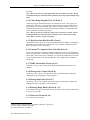
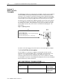
The input image file represents data words and status words. Words 0 and 1 contain
status information for the four channels including process alarms and over and under
range flags. Input words 2 through 5 hold an echo of the analog output value for
channels 0 through 3 respectively. Words 6 through 25 include the HART packet data.
Refer to Chapter 7 for information on how to demultiplex the HART packet data. Input
word 26 holds the message control. Word 27 holds the message response size. Words 28
through 47 hold the message response buffer. Refer to Section 7.3 for more information
regarding input words 28 through 47.
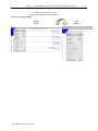
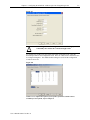
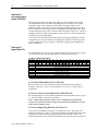
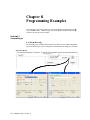
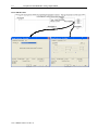
You can access the information in the input image file using the programming software
configuration screen. For information on configuring the module in a MicroLogix 1500
system using RSLogix 500, see Chapter 5; and for the CompactLogix using RSLogix
5000, see Chapter 4.
Section 6.3
Input Data File
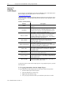
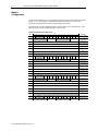
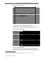
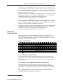
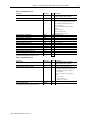
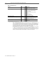
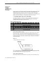
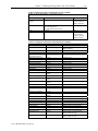
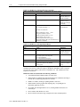
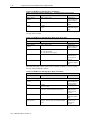
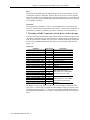
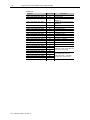
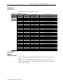
The input data file allows you to access module input data for use in the control program,
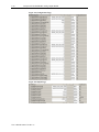
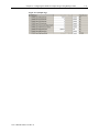
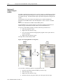
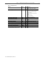
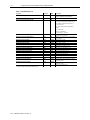
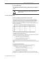
via word and bit access. The data table structure is shown in the table below.
Table 6-1 (Module Input Image)
W o rd /Bit¹ 15
14
13
12
0
OS3 OS2 OS1 OS0
1
0
H3
U3
O3
2
3
4
5
6..25
26
27
28..47
48..69
11
0
10
9
8
7
6
5
Not Us ed
H2
U2
O2
0
H1
U1
Channel 0 Com m and V alue
Channel 1 Com m and V alue
Channel 2 Com m and V alue
Channel 3 Com m and V alue
HA RT P ac k et Data
M es s age S lave Control
M es s age Res pons e S iz e
M es s age Res pons e B uffer
Res erved
4
O1
3
S3
0
2
S2
H0
1
S1
U0
(1) Changing bit v alues is not s uppor ted by all c ontr ollers . Ref er to y our c ontroller manual f or details .
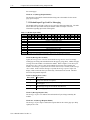
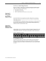
6.3.1 General Status Bits S0 to S3 (Word 0)
Bits S0 through S3 of word 0 contain the general status information for channels 0
through 3, respectively. If set (1), this bit indicates an error (over- or under-range, or
output held).
6.3.2 Out of Service Status Bits OS0 to OS3 (Word 0)
Bits SO0 through SO3 of word 0 indicate whether the associated channel is out of service
(i.e. automatic HART acquisition is suspended).
Note: A channel that is placed out-of-service (i.e. Suspended) will automatically
resume service after three minutes, as long as no pass-through commands are issued
before the three minutes expires.
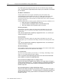
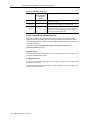
6.3.3 Over-Range Flag Bits O0 to O3 (Word 1)
Over-range bits for channels 0 through 3 are contained in word 1. They apply to all
output types. When set (1), the over-range flag bit indicates an output signal that is at the
maximum of its normal operating range for the represented channel or sensor. The
module automatically resets (0) the bit when the data value falls below the maximum for
User’s Manual 0300217-03 Rev. A
0
S0
O0