1
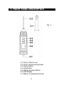
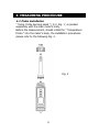
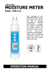
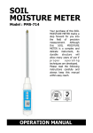
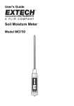
all in one
THERMOMETER
Model : PTM-816
Your purchase of this
METER marks a step
forward for you into the
field
of
precision
measurement.
Although this METER is
a complex and delicate
instrument, its durable
structure
will
allow
many years of use if
proper
operating
techniques
are
developed. Please read
the
following
instructions
carefully
and always keep this
manual
within
easy
reach.
OPERATION MANUAL
TABLE OF CONTENTS
1. FEATURES................................................................1
2. SPECIFICATIONS...................................................... 1
2-1 General Specifications..........................................1
2-3 Electrical Specifications ....................................... 3
3. FRONT PANEL DESCRIPTION..................................... 4
3-1 Temp. Probe Cover..............................................4
3-2 Temp. Probe Sensing Head.................................. 4
3-3 Power Button...................................................... 4
3-4 Hold Button........................................................ 4
3-5 Display Reverse Button........................................ 4
3-6 LCD Display........................................................ 4
3-7 Battery Compartment/Cover.................................4
4. MEASURING PROCEDURE..........................................5
4-1 Probe installation.................................................5
4-2 Temperature measurement..................................6
4-3 Data Hold........................................................... 6
4-4 Display Reverse...................................................7
4-5 Change the ℃, ℉ unit.........................................7
5. BATTERY REPLACEMENT........................................... 8
1. FEATURES
*
*
*
*
*
*
*
*
*
*
Heavy duty and all in one pen type thermometer.
℃/℉, 0.1 degree.
Meter can default the measuring unit to ℃ or ℉.
Two type display, normal or reverse, easy for
operation.
IP67, water proof and protection.
Data hold to freeze the display value.
Bright LCD display.
Microprocessor circuit ensures high accuracy and
provides special functions and features.
Operates from DC 1.5V ( UM4/AAA ) x 4 PCs batteries.
Durable, long-lasting components, enclosed in strong,
compact ABS-plastic housing.
2. SPECIFICATIONS
2-1 General Specifications
Display
Temp. unit
Circuit
Temp.
Sensor
LCD size : 28 mm x 19 mm.
℃ or ℉ with default.
Custom one-chip of microprocessor LSI
circuit.
Type K thermocouple.
1
Data Hold
Sampling Time
Protection
Operating
Temperature
Operating
Humidity
Power Supply
Power Current
Weight
Dimension
Freeze the display reading.
Approx. 1 second.
IP67, water proof.
0 to 50 ℃.
* Meter only.
Less than 80% R.H.
* Meter only.
DC 1.5 V battery ( UM4/AAA ) x 4 PCs,
Approx. DC 6.5 mA
142 g/ 0.31 LB. @ Battery is included.
Meter :
150 x 40 x 40 mm ( 5.9" x 1.6" x 1.6" ).
Temp. Probe Sensing Head :
Accessories
Included
Optional
Accessory
70 mm x 3.2 mm Dia.
* Instruction manual.................. 1 PC
* Temp. probe protection
cover......................................1 PC
* Soft carrying case with sash
( 210 x 80 x 50 mm ), Model : CA-52A
2
2-2 Electrical Specifications
(23± 5 ℃)
Resolution
Range
Accuracy
0.1 ℃
0.1 ℉
-40.0 to 230.0 ℃
-40.0 to 446.0 ℉
± ( 0.4 % + 0.8 ℃ )
± ( 0.4 % + 1.5 ℉ )
* Above specification tests under the environment RF Field
Strength less than 3 V/M & frequency less than 30 MHz only.
3
3. FRONT PANEL DESCRIPTION
Fig. 1
3-1
3-2
3-3
3-4
3-5
3-6
3-7
Temp. Probe Cover
Temp. Probe Sensing Head
Power Button
Hold Button
Display Reverse Button
LCD Display
Battery Compartment/Cover
4
4. MEASURING PROCEDURE
4-1 Probe installation
" Temp. Probe Sensing Head " ( 3-2, Fig. 1 ) is packed
sepeartely with the main meter's body.
Before the measurement, should install the " Temperature
Probe " into the meter's body, the installation procedures
please refer to the following Fig. 2.
Fig. 2
5
4-2 Temperature measurement
1)Turn on the meter by pressing the " Power Button "
( 3-3, Fig. 1 ) momentarily.
* Press the " Power Button " ( 3-3, Fig. 1 )
momentarily again will turn off the meter.
2)Insert the '" Temp. Probe Sensing Head " ( 3-2, Fig. 1 )
into the material that intend to measure the temperature.
The " Display " ( 3-6, Fig. 1 ) will show the temperature
value that sensing from the probe's head.
* The max. measuring operation
temperature of the " Temp. Probe
Sensing Head " ( 3-2, Fig. 1 ) is
230 ℃, please do not measure the
Temp. value over it.
* After finish the measurement, install the
" Temp. Probe Cover " ( 3-1, Fig. 1 ) into the
" Temp. Probe Sensing Head " ( 3-2, Fig. 1 ).
4-3 Data Hold
1)During the measurement, press the " Hold Button "
( 3-4, Fig. 1 ) momentarily to hold the measured
value. The LCD will show a " HOLD " symbol.
2)Press the" Hold Button " once again to release the
data hold function.
4-4 Display Reverse
During the measurement, press the " Display Reverse
Button " ( 3-5, Fig. 1 ) once will reverse the display
direction for the user convenience.
* Press the " Display reverse button " once again will
return to the normal display.
6
Normal
display
Reverse
display
4-5 Change the ℃, ℉ unit
1)Refer to Fig. 3 , open the " Battery Cover " ( 3-7, Fig. 1 ),
use the finger ( middle finger ) to hold the battery cover
and let the snap contact the batteries completely.
2)Turn on the meter by pressing the " Power Button "
( 3-3, Fig. 1 ) momentarily.
Press the " ℃, ℉ Button " ( Fig. 3 ) momentarily will
switch the Temp. unit from " ℃ to ℉ " or " ℉ to ℃ ".
3)After the Temp. unit is selected, then release
the finger from the battery snap and install the
" Battery Cover " ( 3-7, Fig. 1 ) again..
Now the Temp. unit is selected and with default.
If power on the meter again, the selected Temp.
unit will present.
℃, ℉ Button
Fig. 3
Use the finger ( middle
finger ) to hold the
battery cover and let the
snap contact the
batteries completely.
7
5. BATTERY REPLACEMENT
* Replace the batteries when the left corner of the LCD
displays the low battery icon "
", using 4 fresh
1.5 V ( UM4, AAA ) batteries.
* To change the batteries, open ( rotate clockwise direction )
the " Battery Cover " ( 3-7, Fig. 1 ).
* Make sure the " Battery cover " (3-7, Fig 1) is secured
after changing the batteries.
8
0710-PTM816