1
Errata
Title & Document Type: 3048A Phase Noise Measurement System Reference Manual
Manual Part Number: 03048-90002
Revision Date: September 1989
HP References in this Manual
This manual may contain references to HP or Hewlett-Packard. Please note that HewlettPackard's former test and measurement, semiconductor products and chemical analysis
businesses are now part of Agilent Technologies. We have made no changes to this
manual copy. The HP XXXX referred to in this document is now the Agilent XXXX.
For example, model number HP8648A is now model number Agilent 8648A.
About this Manual
We’ve added this manual to the Agilent website in an effort to help you support your
product. This manual provides the best information we could find. It may be incomplete
or contain dated information, and the scan quality may not be ideal. If we find a better
copy in the future, we will add it to the Agilent website.
Support for Your Product
Agilent no longer sells or supports this product. You will find any other available
product information on the Agilent Test & Measurement website:
www.tm.agilent.com
Search for the model number of this product, and the resulting product page will guide
you to any available information. Our service centers may be able to perform calibration
if no repair parts are needed, but no other support from Agilent is available.
HP 3048A
Phase Noise
Measurement System
Reference Manual
m
HEWLETT
PACKARD
Manual Boxed Set HP Part 03048-90002 (Reference Manual
(03048-90002) not available separately)
Notice
This document contains proprietary information which is
protected by copyright. All rights are reserved. No part of
this document may be photocopied, or reproduced without
prior written consent of Hewlett-Packard Company.
This material may be reproduced by or for the U.S.
Government pursuant to the Copyright License under the
clause at DFARS 52.227-7013 (APR 1988).
Copyright (c) 1987 Hewlett-Packard Company
Hewlett-Packard Company
Spokane Division
24001 E. Mission
Liberty Lake, WA 99019-9599, U.S.A.
Software
Versions
This manual applies directly to instruments with software
version numbers:
H P 3048A Software Version: REV: A.02.00 and Above
Printing History
First Edition: 6/88 Printed in U S A
Second Edition: 9/89 - Printed in U.S.A.
rev.05SEP89
Volume 1 Contents
Softkey Index
Chapter 1, General Information
Introduction
1-1
Chapter 2, Measurement Definitions
Introduction
Type/Range
Instr. Params (Instrument Parameters)
Calibr Process (Calibration Process)
Source Control
Define Graph
Test Files
2-1
2-3
2-13
2-41
2-101
2-115
2-121
Chapter 3, Graphics Functions
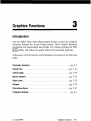
Introduction
Param Summary (Parameter Summary)
Define Graph
Marker ON/OFF
Slope Lines
Plotters
Plot w/o Spurs (Plot without Spurs)
3-1
3-3
3-19
3-23
3-25
3-29
3-31
Chapter 4, Computed Outputs
Introduction
Integr Noise (Integrated Noise)
Sigma vs. Tau
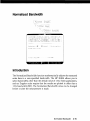
Normalized Bandwidth
3 Osc. Compar. (Three Oscillator Comparison)
2 Osc. Compar. (Two Oscillator Comparison)
Spur List
4-1
4-3
4-9
4-15
4-19
4-23
4-27
Volume 2 Contents
Chapter 5, Special Functions
Introduction
Test Mode
Carrier Type
FFT Segmnts (HP 3561A Segments)
RF Segmnts (RF Spectrum Analyzer Segments)
Noise Monitor/NewNse Monitor
11848A Control
3048A Sys Chk (3048A System Checks)
5-1
5-3
5-9
5-13
5-23
5-29
5-35
5-43
Chapter 6, System Configuration
Introduction
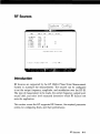
RF Sources
RF Analyzers
Down Converters
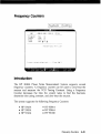
Frequency Counters
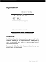
Digital Voltmeters
Controllers
Mass Storage Devices .
Plotter
System Clock
Load Alternate Program
Additional Equipment
6-1
. 6-3
6-23
6-31
6-45
6-47
6-49
6-51
6-55
6-59
6-61
6-63
Chapter 7, Quick Reference
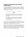
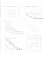
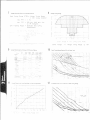
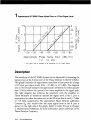
1 Approximate HP 3048A Phase Noise Floor vs.
R Port Signal Level
2 HP 3048A Phase Noise Floor and Region of Validity
of£(/) = % Q
3 Phase Noise Level of Various HP Sources
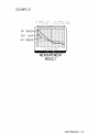
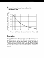
4 Increase in Measured Noise as Reference Source Noise
Approaches DUT Noise
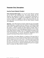
5 Approximate Sensitivity of Delay Line Discriminator
6 AM Calibration
7 Voltage Controlled Source Tuning Requirements
8 Voltage Tuning Range vs. Center Voltage
9 Tuning Characteristics of Various VCO Source Options
10 Peak Tuning Range Required Due to Noise Level
11 Phase Lock Loop Bandwidth vs. Peak Tuning Range
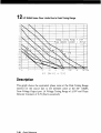
12 HP 3048A Noise Floor Limits Due to Peak Tuning Range . . . .
7-2
7_4
7-6
7-8
7-10
7-12
7-14
7-16
7-18
7-22
7-24
7-28
Chapter 8, Messages
Introduction
Numbered Error Messages
Unnumbered Error Messages
Reference Messages
Warning Messages
Status Messages
8-1
8-2
8-19
8-21
8-28
8-29
Index
0.001 Hz offset measurements, 5-20
1 Hz bandwidth, 4-15
2 device comparison, see: 2 Osc. Compar.
2 Osc. Compar., 4 23
2 oscillator comparison, see: 2 Osc. Compar.
2 source comparison, see: 2 Osc. Compar.
3 device comparison, see: 3 Osc. Compar.
3 Osc. Compar., 4-19
3 oscillator comparison, see: 3 Osc. Compar.
3 source comparison, see: 3 Osc. Compar.
10 MHz A used with HP 8662A/63A, 6 11, 6-13
10 MHz B used with HP 8662A/63A, 6-14
11848A Control, 5 35
3048A Sys Chk, 5-43
A
A vs. B file, 4 21, 4 25
A vs. C file, 4-21
absolute system noise floor HP 11729C, 6-35
acc'y spec degrad, 2-54, 3 9
Access Graph, 5, 3-1
accuracy, 1-12. see also: specifications
accuracy specification degradation, 2-54, 3 9
adjustments (HP 11848A), 5 44. see also: HP 3048A Calibration Manual
advanced user, 5-1
Allan Variance, 4 10
AM calibration, equivalent fc$, 4 89, 7 12
Index
1
AM Detector, 2-8, 2-89, 6 63
Constant, 2-89
filter, 6 63
AM measurements HP 11729C, 6-43. see also: HP 3048A Operating Manual
AM Noise,
instrument parameter, 2 38
calibration process, 2 89
measurement type, 2-7
AM rejection, 2- 7
AM sensitivity, 2-89
amplifiers, 2-6, 6-64
assumed pole, 2 55, 3-11; 5-5
ATTEN1, 5-37
ATTEN2, 5-37
ATTEN3, 5-37
attenuators, 6 63
Aux Monitor port, 2-46, 6 46
averages,
FFT, 2 12, 5 15
span marking, 4-28
averaging, 2 12, 5 15
B
BW, 4-16, 5-16, 5 26
B vs. C file, 4-21
backup software files, see: copying files
bandwidth, 5 16, 5-26
0 Hz, 4-17
normalized, 4 15
baseband noise measurement type, 2-10
beatnote, 2-46, 7 24. see also: HP 3048A Operating Manual
beatnote calibration w / o PLL, 2 65
bin, 4-5
block diagram HP 11848A, 5-42
2
Index
c
cal system, 7, 5 44. see also: HP 3048A Calibration Manual
CALDATAHI, 5-45. see also: HP 3048A Calibration Manual
CALDATALO, 5-45. see also: HP 3048A Calibration Manual
Calibr Process, 2-41
calibration,
constant, see: Phase Detector Constant; VCO Tuning ConstantDiscriminator Constant, AM Detector Constant
data, see: HP 3048A Calibration Manual
periodic, see: HP 3048A Calibration Manual
process, 2 41
spur, see: double sided spur; single sided spur; spur test
tone, 6-25
capture range, 7-14. see also: HP 3048A Operating Manual
carrier frequency, 3-5, 3-15
AM Noise, 2 38
w/FM Discriminator, 2-35
w/PLL, 2 14
w / o P L L , 2-31
carrier noise test set (HP 11729C), 6-32
carrier type, 5 9
center voltage, 2-17, 3-6, 7-16
center voltage of VCO tuning curve, 2 17, 3 6, 7 16
clearing CALDATA, 7, 5-46
clip left, 3-26
clip right, 3-26
closed PLL bandwidth, 3-10, 5-5
comb line frequencies, 6 33
Computed Outputs, 4-1
computers, 1 9 , 6 49
computer accessories, 1-9
controllers, 6-49
copying files, 6 52
test files, 2-124
result files, 3 15
Index
3
counters, 6-45
couplers, 2-73, 6-64
Create Dir. (create directory), 2-126, 3 18
Current Detector Constant, 2-44
w / o PLL, 2 59
Cutler, 4-11
cutoff frequency {fh)> 4-9
CW Carrier Type, 5-9
D
DAC1, 5-37
DAC2, 5-37
DAC3, 5-37
Dae tests, 5 44
data files, 6-52. see also: test files; result files
Data Type, 2 117, 4 4
dBc/Hz, 4-16
dc block, 2 8, 6 64
DC FM,
HP 8662A/HP8663A, 2-29, 6-10
deviation, 2 16. see also: VCO Tuning Constant
deer, hpf, 8, 5-30
deer, lpf, 8, 5 30
Default,
Test File, 2-122
Result File, 3-14
Define Graph, 2-115, 3-19
Define Msrmnt, 2-1
Definite Integral Value, 4-3
delay line discriminator, 2 79, 2 109, 7 10
delete entry, 8, 4-4
delete file, 2 123, 3 15
delete segment, 5-19
derive from measured +/— dc peak w / o PLL, 2-61
Detect. Input Frq., 3-5. see also: Detector/Discr.
4
Index
Detector Constant, 3-7, 7-2. see also: Phase Detector Constant
estimating, 2-91, 7 2
w/PLL, 2 43
detector selection,
AM Noise, 2 39
w/FM Discriminator, 2-37
w/PLL, 2-26
w / o PLL, 2-33
Detector/Discr.,
Input Frequency AM, 2-39
Input Frequency FM Discriminator, 2-36
Input Frequency w/PLL, 2-15
Input Frequency w / o PLL, 2 32
Device Under Test (DUT), 2 102, 3-11
digital voltmeter, 6-47
direct comparison, 4-19
directional coupler, 2 73, 6-64
directory, 2-126, 3-18
disc drives, 1-10, 6-51
discontinuity, see: HP 3048A Operating Manual
discriminator (delay line), 2-79, 7-11
discriminator sensitivity, see: Discriminator Constant
Discriminator Constant, 2-75
estimating, 2-78
display resolution for the HP 3561 A, 5 17
dividers, 2 6
Documentation Update Service, 1-4
documentation updating, 1 4
Double Sided Spur,
calibration tone, 6-29
AM Noise, 2-93
w/FM Discriminator, 2-81
w / o PLL, 2-67
down converter, 3 12, 6 31
Drift Tracking Range, 2-19, 7-14
rev.05SEP89
Index
5
DUT, 2-102, 3-11
DUT source, 2 108
dynamic signal analyzer, see: HP 3561A
E
EFC, 6-8, 7-18
enhanced tuning range, 2 27, 7 18
entered K_VCO, 3-5. see also: VCO Tuning Constant
erase lines, 3 26
Error Messages, 8 2
Eval Allan, 9, 4-10
eval intgrl, 10, 4 4
eval sigma, 10, 4-10
external timebase, 3-11. see also: external reference tuning
external controller, 6-2
external detectors,
phase, 2-26
w/FM Discriminator, 2-37
w/PLL, 2 26
w / o PLL, 2-34
external reference tuning, 6-12
F
fh> 4-9
F SWITCH NUMBER, 5-38
FFT Analyzer, 6-2
FFT Segment, 5-13
FFT Segmnts, 5 13
filters, 2-6, 6-63
flicker of freq., 4-13
flicker of phase, 4-13
floppy disc, 6 51
FM deviation, 2-16, 2-85. see also: VCO Tuning Constant
FM discriminator calibration, 2 75
FM rate, 2-85
6
Index
rev.05SEP89
FM rate and deviation calibration w/FM discriminator, 2-85
FM spectral density, 2 117, 3-21
Fnctl. Chk., 10, 5-44
fractional frequency deviation, 4-9
freeze files, 10, 4-21, 4-25
frequency counter, 6-2, 6-45
frequency fluctuations, 2 76
frequency multipliers, 2-6
frequency offset range, 1 3, 5-20
frequency range, 1-12, 2-12, 5-25
function generator, 6 2
functional checks, 10, 5-44
G
GAIN1, 5-37
GAIN2, 5-37
GAIN3, 5-37
General Information, 1-1
graph,
AM calibration, equivalent £:$, 7-12
center voltage, 3 6, 7-16
peak tuning range noise floor, 2-21, 7-28
peak tuning range required, 2-23, 7 22
phase lock loop bandwidth, 2-22, 7-24
VCO tuning characteristics, 2 50, 7-18
voltage controlled source tuning requirements, 2-19, 7-14
Graph Type, 2 117, 3-21
Graphic Functions, 3-1
H
H SWITCH NUMBER, 5-38
hard copy, 10, 3-26
hard disc, 6-51
HEWLETT-PACKARD FACTORY (test file), 2-122
HP 11729C, 1-19, 6-20, 6-31
Index
7
HP 11729C specs, 4, 6-33
HP 11808A, 6-61
HP 11848A block diagram, 5-42
HP 11848A Interface, 1-2, 5-35, 5-43
HP 11848A LNA, 3-12, 5 9, 7-2
HP 3048A, 1-2
HP 3048A option K21, 2 8, 6 63
HP 3048A reference source options, 1-7
HP 3048A spectrum analyzer options, 1 8
HP 3048A system options, 1-8
HP 310, 6 49
HP 320, 6-49
HP 33330C low barrier schottkey diode detector, 2-91 6-63, 7 12
HP 3561A dynamic signal analyzer, 1 2, 2-8, 5-13, 5 30
HP 3585A/B, 6-24
HP 5316A/B, 6-45
HP 5343A, 6 45
HP 5384A, 6-45
HP 5385A, 6 45
HP 5386A, 6-45
HP 71000, 6 24
HP 82315B, 6-49
HP 8566A/B, 6-24
HP 8567A, 6-24
HP 8568A/B, 6-24
HP 8642A, 6-16
HP 8656B, 6 18
HP 8656A, 6-19
HP 8662A/HP 8663A, 6-7
HP 9836A, 6-49
HP 9836C, 6-49
HP EXAMPLE (test file), 2-122
HP-IB address, 6-0. see also: HP 11848A Service Manual
HP TEST (test file), 2 122
8
Index
I
Ignore Out Of Lock Test Mode, 10, 5-8
injection locking, 2 48, 2 56, 7-22. see also: HP 3048A Operating Manual
Instr. Params, 2-13
Instrument Parameters, 2-13
Int. Adj'mt, 5-44. see also: HP 11848A Serv./HP 3048A Cal. Manuals
Integr Noise, 4 3
Integrated Noise, 4 3
interface, see: HP 11848A
isolation, 2 48
J
Jitter, 4-29
K
kd, see: Discriminator Constant
K_Detector method, 3 7
known osc, 4-24
fc$, 2-43. see also: Phase Detector Constant
kv [Hz/v], see: VCO Tuning Constant
K_VCO method, 3 8. see also: VCO Tuning Constant
L
£ ( / ) , 2-117, 3-21, 4 4
lag-lead filter, 5-38, 7 22
line stretcher, 2-61, 2-82, 2 108, 6 64
LNA, 3- 12, 5 9, 5-42, 7-2
Load Alt., 11, 6 61
load alternate program, 6 61
loadCALDATA, 11, 5-46
load file, 11, 2 126, 3-14
load file test file, 2 123
lock loop, 11, 5-30
reu.05SEP89
loop
loop
loop
Low
holding range, see: Drift Tracking Range
suppression, 2-54, 3 9
suppression verification, 2-54, 3-9
Noise Amplifier, 3-12, 5 9, 5 42, 7 2
M
maximum x coordinate, 3 20
manual updates, 1 4
Marker,
(RF Analyzer), 12, 5-31
3561A, 12, 5-31
ON/OFF, 12, 3 23
mass storage, 2 123, 3-14 6-51
mass storage devices, 1-10, 6 51
maximum acceptable clipping, 5-11
maximum y coordinate, 3-20
measure the detector constant w/PLL, 2 47
measurement,
averages, 2 12, 4-28, 5-15
bandwidth, 5-16, 5-26
definitions, 2 1
FFT, 5 16
range, 2-12, 5-20
resolution, 5-14, 5-25
software, 1 2
time, 5 14
type, 2-4, 3-4
Messages, 8-1
Numbered Error, 8 2
Reference, 8 21
Status, 8-29
Unnumbered Error, 8 19
Warning, 8 28
meter, 2 49, 2 88
meter sensitivity, 2-49, 2 88
10
Index
microwave phase detector, see: Option 201
minimum averages, 3 -4
minimum x coordinate, 2-116, 3 20
minimum y coordinate, 2-117, 3 20
rev.05SEP89
Index
10.1
mixer sensitivity, see: Phase Detector Constant
modulation analyzer, 2-67, 2 93, 6 63
move down, 3 26
move up, 3-26
multimeter, 6-47
N
N, 4-9
National Bureau of Standards Traceability NBS, 1-11
new line, 3-26
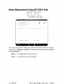
New Noise Monitor, 12, 5 30
New Measurement, 12. see also: HP 3048A Operating Manual
next page, 13, 3-14
next type, 13, 2 4
Noise, 4-17
data plotted in a 0 Hz bandwidth, 4 17
floor level w/PLL, 2-20, 7-28
Input, 2-47
power, 4-7
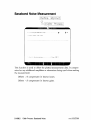
Measurement Using the HP 3561A Only measurement type, 2-8
voltage, 2-8, 2-10
voltage measurements, see: baseband noise measurement type
Noise Monitor, 5 29
Noise Monitor/Newnse Monitor, 5-29
Normal Test Mode, 5-4
Normalized Bandwidth, 4-15
Non-linear Tuning Constant, 2-24
O
offset frequency range, 1 12, 2 12, 5 20, 5-25
Omit Spurs, 13, 4-4, 4-10
One Osc, 4-21, 4 25
Operator's Training, 1-2
Option 001, 1-7
Option 002, 1 7
rev.05SEP89
Option 003, 1-7
Option 004, 1-7
Option 005, 1 7
Option 006, 1-7
Option 101, 1-8
Option 110, 1 8
Option 201, 1-8
Option 202, 1-8
Option 910, 1 8
Out of Lock, 5-8, 6 48. see also: HP 3048A Operating Manual
overload, 2 112, 6-48
P
panel meter, 2-49, 2-84
Param Summary, 3 3
Parameter Summary, 3 3
Parm_Dir, 2 126
Parmjnumber), 2 124
peak deviation, 2-16. see also: VCO Tuning Constant
peak phase deviation, 2-69
peak tuning range, 2 18, 3-10
maximum HP 11729c, 6-41
noise floor, 7-28
required, 7 22
peak volts, 2-61
Perf. Tests, 14, 5-44, 6 29
Performance Tests, 14, 5-44, 6 29
performance verification capabilities, 5 43
Phase Detector, 3-7
Constant w/PLL, 2-43
Constant w / o PLL, 2 -57
sensitivity, see: Phase Detector Constant
phase lock loop bandwidth, 2-18, 2-22, 7-24, 7-26
phase lock loop suppression, 2-54, 5-4
phase modulation spectral density, 2-117, 3- 21
12
Index
rev.05SEP89
Phase Noise,
of various HP sources, 6-3, 7-6
Using an FM Discriminator, 2 35
Using a Phase Lock Loop measurement type, 2-4
Without Using a PLL, 2 31
Without Using a PLL measurement type, 2-6
phase shifter, 2 108, 6-64
phase slope, 2-43, 3-7, 7 4. see also: Phase Detector Constant
PLL BW, 2-23, 2 54, 7-24
PLL suppression curve, 5 5
Plot W / O Spurs, 14, 3 31, 3-32
plot without spurs, 14, 3-31 3 32
plotter, 6 2, 6-55
plotters (outputting), 3-29
plotter pens, 6-56
power meters, 6 63
power splitters, 6-64
printer, 1-10, 6-2
printers/plotters, 1-10, 6-55
PTR, 2 18, 3-10, 7-22
Pulsed Carrier Type, 5-9
Q
quadrature meter, see: meter
Quick Reference, 7-1
R
Random Walk of Freq., 4 13
Read Dir, 15, 2 123, 3-15
real time, 5 29. see also: Noise Monitor
real time noise measurements, 5-32
reference line, see: specifications lines; slope lines
Reference Messages, 8 21
Reference Noise vs. DUT Noise, 7 8
Reference Source, 3-11
Index
13
region of validity, 7-4
relation of L(f) to Allan Variance, 4 -13
remove line, 16, 3-26
repeat measurement, see; HP 3048A Operating Manual
residual (two-port), 2-6
resolution, 5-25
resu_, 3-15
Result Files, 3-13
return loss noise input, 2 49
RF (spectrum) analyzer, 5-23, 6-2, 6-23, 6-25
RF segment table, 5-24, 6-25
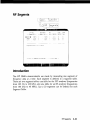
RF segmnts, 5 23
RF source, 6-2
rms modulation, 4 3
S
segment table, 5-23
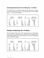
increasing resolution, 5 21
measurement time, 5-19
specifying offsets, 5 22
SELECTED K SWITCHES, 5-38
SELECTED L SWITCHES, 5-38
SELECTED S SWITCHES, 5 38
Set Line, 3 26
Sigma vs. Tau, 4-9
signal level, 7 2
single point, 5-29. see also: Noise Monitor
Single Sided Spur,
calibration tones, 6-29
AM Noise, 2-97
w / o PLL, 2-71
Single-Sideband Phase Noise, 2 117, 3 21, 4 4
Slope Lines, 3 25
slope versus maximum tau, 4-12
small angle criteria, 2 87
14
index
small angle criteria L(f), see: region of validity
sv(f), 2 -117, 3-21,4-4
Software Materials Subscription (SMS), 1-5
Software Notification Service (SNS), 1-5
Software Release Bulletin, 1-6
Software Status Bulletin, 1 6
Software Updating, 1 5
Solve A,B,C, 4 21
Solve for B, 4-25
Source Drift (see Drift Track Range), 2-19
span, 5 31
Spec Lines, 2-118
Special Functions, 5 1
Specifications, 1-11
Specification Lines, 2-118
Spectral Density,
of Fractional Frequency Fluctuations, 2 117, 3-21, 4-4
of Frequency Fluctuations, 4 4
of Phase Fluctuations, 4-4
spectrum analyzer, 1-10, 6-2
output HP 11848A, 6-29
phase detector output, 6 25
S$(f), 2-117, 3 21,4-4
Spur List, 4 27
spur marking criteria, 4-28
Spur Test, 5-44. see also: HP 3048A Calibration Manual
SRB, 1-6
SRM, 6 51
SSB, 1-6
Start Offset Freq, 3-4
Status Messages, 8-29
Stop Offset Freq, 3 4
Store File, 2 125, 3-15
sweep time, 5-26
switch (refer to 11848A control), 5-35
rev.05SEP89
Sy{J), 2-117, 3 21, 4-4
System Config, 6-1
System Clock, 6 59
System Configuration, 6-1
T
t, 4 9
tau (r), 4-9
table of data points for supported analyzers, 4-6
Take Sweep, 19, 5-31
Test Files, 2-121
loading, 2-126
storing, 2 125
Test Mode, 5-3
Test Result File, 3-13
Three Osc. Comparison, see: 3 Osc. Compar.
Time Record Length, 5-17
Title, 2 116, 3 20
Troubleshooting, see: HP 3048A Cal./HP 11848A Serv. Manuals
Trouble Shoot Test Mode, 5-4
tune port input resistance, 2-18, 3-8
tune port resist, 2-18, 3-8
tune voltage output port on the rear panel, 2-17
Tune Voltage Range, 2-17, 3-6
Tune Voltage Rnge, 2 17, 3 6
Tuning,
Constant, 2 50. see also: VCO Tuning Constant
Curve, see: VCO Tuning Constant
sensitivity, see: VCO Tuning Constant
slope, see: VCO Tuning Constant
Two Osc. Comparison, see also: 2 Osc. Compar.
Two Port (residual), 2-6
Type/Range, 2 3
16
Index
reu.05SEP89
u
uncal light, 6-29
unmarked spurs, 4-22, 4-26, 4-28
Unnumbered Error Messages, 8 19
Update Dir, 2-123, 3-15
v
V/y/Hz, 2-75
V/Rad, 2-57
VCO slope, see: VCO Tuning Constant
VCO tune port input resistance, 2-18
VCO Tuning Constant, 2-16, 2-50, 3-8, 5-8, 7-18
VCO tuning linearity, 2 24
Vectra Viper, 6-49
video bandwidth, 5 26
VNOMS, 5-45. see also: HP 3048A Calibration Manual
Voltage Controlled Source Tuning Requirements, 7 14
Voltage Tuning Range of VCO, 2-17
Voltmeter, 6 2, 6 47
VTR, 2-17
W
Warning Messages, 8-28
white freq., 4-13
white phase, 4 13
X
x coordinate, 2-116
Y
y coordinate, 2-117
Index
17
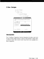
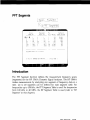
Softkey Index
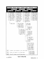
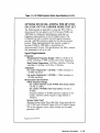
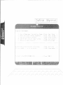
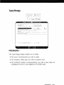
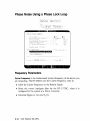
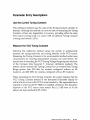
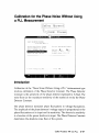
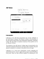
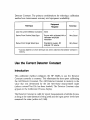
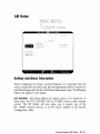
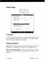
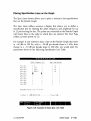
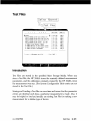
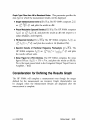
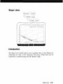
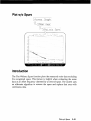
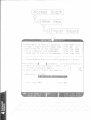
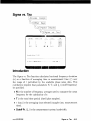
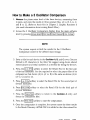
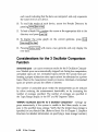
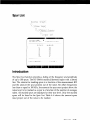
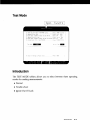
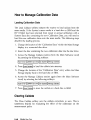
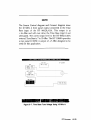
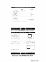
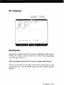
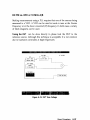
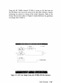
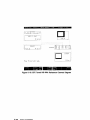
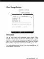
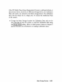
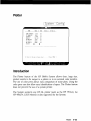
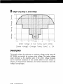
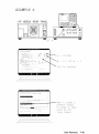
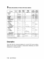
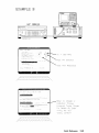
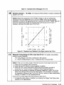
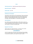
This section includes a Softkey Map and Softkey Descriptions Table. The
Softkey Map provides an overview of the HP 3048A's softkey menu
structure.
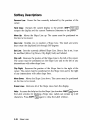
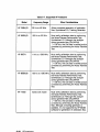
The softkeys are listed in alphabetical order in the Softkey Description
Table. The softkey descriptions briefly describe the function of each
softkey. References to additional information are included in the table.
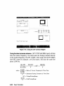
Softkey Map
pg. 3
Softkey Descriptions Table
pg. 4
Softkey Index
1
HF'SOfSFt PHASE NOI^E SYSTEM MAIN SOFTWARE LEVEL
MAKE P- FHASt NO!'..E rCASMPFMFNT:
U
,"')
Def ;ns=
Keasu-e
H.
MR
[I,
tne- nseasui ciaeot
[ P ■ess 'Lief j u t "ferim- J
the rv.nse. . .
■Reppat Hr.rimt' ]
using -iiri-nnt c a l i b r . o y i s t a n t s . . . [ '"
'NEW
Msrren'.' .1
aftpr n e r e r a t i n u new ■.o'lEtantB. . f P
iji?5':r]bp H i " system hai Jwa'e ■:onf inurst
a.:•-*?&!-. the l a t e s t graph of tP B t r e s u l t s
Inarf a tv|Ji-.al nsMaurPiappt and i t s yi ad
l-it-r f-_>rm arlvanrr-ri-u-ipr ope1 a!i'.-n=. . . .
'System
floiess
Sy^tPm
'>■:.
.;Mif i q '
-i-raph'
r-rpr,.--!
-ui-ot i
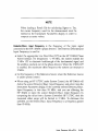
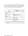
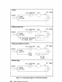
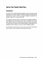
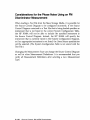
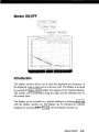
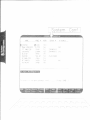
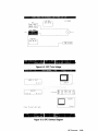
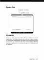
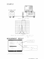
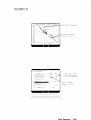
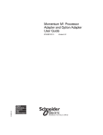
Figure 1. Main Software Level Display
2
Softkey Index
HP3048A
Phase
Noise
System
[Repeat M s r m n t ^ ^ B N e w
Define Msrrnnt^MAccess
Copy
Instr.
Params
Redraw
Calibr
Process
Plot
Param
Control
Result
Source
Test
Define
bz^JParam
Files
Graph
Other
Spec
Summary
—D|
Test
FFT
1 1
RF
-1
Keys
w/o
Slope
Spurs]
darker
—J>; 3
^
—^
Load
Type
System
i=[)| Mass
Segmnts
Plotter
Sys
Chk
Dae
Tests
^
Outputs
Spur
Delete
Mode
/
—'}:
Config
Specs;
Instr.
Config
Clock
Storage
Pens
Int. Adj'mnt,
ON/OFF |
mputd
Store
11729C
Segmnts
3048A
Lines
j
Monitor
Carrier
-H
Graph
Control
Monitor
NewNse
-;r
->\
Files
-^Piot
Lines
Noise
-r<
Graph
Define
11848A
^
Data
Redrew
Level
Funct^^^^^|Systern~Confi(
n
Graticl
Summary
Software
M s r m n t ^ ^ B System Preset |
G r a p h ^ ^ f Spcl.
Hard
Type/Range
Main
List
j
Adjust
A3
| Adjust
A4
Perf.
Tests
Osc.Compor.
2
Noise
Osc.Campar.
Integr
—!)iSigma
vs.
Floori
Noise
Noise
Spur
Tau
^
Fncti.
Flat
Accy.
Chk"'
^>
Select
Test
Test Ail
Printer
.Cal
ON/OFF:
System,
Col
to
100
Cal
to
40
Cal
Int
Eval.
^Printer
-
Accesses
DONE
— Returns
a
Brief
Description
of
the
Current
Display.
Srcs
Caldata
ON/OFF"
Manage
HELP
Caldata
-A.
Load
ABORT -
Stops
rev.22SEP89
the
the
Program
Process
to
and
the
calls
Previous
Previous
Menu.
Menu.
kHzi
MHz !
Coldata |
Store
Caldatal
Clear
Caldata
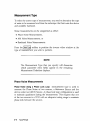
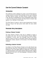
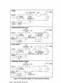
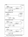
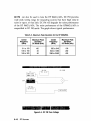
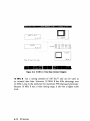
Figure 2. Softkey Map
Softkey Index
3
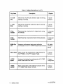
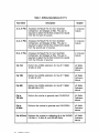
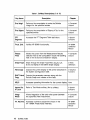
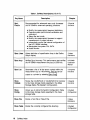
Table 1. Softkey Descriptions (1 of 17)
Description
Key Name
4
Chapter
0 to 100
kHz
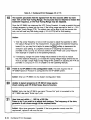
Selects the CALDATALO calibration data for storing,
loading, or zeroing.
5 Special
Functions
.1 to 40
MHz
Selects the CALDATAHI calibration data for storing,
loading, or zeroing.
5 Special
Functions
2 Osc.
Com par.
Determines the noise level of a single device using
two devices.
4 Computed
Outputs
3 Osc.
Com par.
Determines the noise level of each of three devices.
4 Computed
Outputs
3048A Sys
Chk
Accesses performance testing and calibration
procedures for the HP 11848A Phase Noise Interface.
HP 3048A
Calibration
Manual
3561A Span
Steps through the measurement ranges defined for
the HP 3561A in the FFT Segment Table.
5 Special
Functions
11729C
Specs
Accesses the display for specifying the HP 11729C
carrier noise comb line filters.
6 System
Configuration
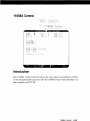
11848A
Control
Allows manipulation of the internal hardware of the
HP 11848A Phase Noise Interface.
5 Special
Functions
Softkey Index
reu.22SEP89
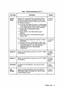
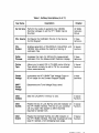
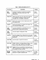
Table 1. Softkey Descriptions (2 of 17)
Key Name
Access
Graph
Description
Chapter
Displays the noise graph that is presently stored in
memory and accesses the Graphics Functions and
Computed Outputs Functions. Allows you to perform
the following functions:
• Access the Parameter Summary, a summarization
of the measurement definitions used to obtain the
current measurement results. (Parm Summary)
• Access files of measurement results.
(Result Files)
• Place marker on the measurement graph.
(Marker)
• Place slope lines on the measurement graph.
(Slope Lines)
3 Graphics
Functions
• Display and plot measurement results in various
bandwidths.
• List spurs found in a measurement. (Spur List)
• Numerically manipulate the measurement results
to generate Sigma vs. Tau (Allen variance),
Integrated Noise and Three Oscillator
Comparisons.
4 Computed
Outputs
Adjust A3
Selects the Adjustment procedure for the HP 11848A
A3 Assembly.
HP 3048A
Calibration
Manual
Adjust A4
Selects the Adjustment procedure for the HP 11848A
A4 Assembly.
HP 3048A
Calibration
Manual
AM Detect.
Configures the AM Detector in the Source Control
display.
2 Meas.
Definitions
AUX.
Caldata
Causes cal data generated by the Noise Flatness
Performance Test to be erased from memory when
using Manage Cal Data.
5 Special
Functions
Softkey Index
5
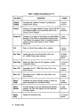
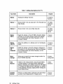
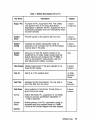
Table 1. Softkey Descriptions (3 of 17)
Key Name
A vs. B File
6
Description
Chapter
Accesses the Result File for the 3 Oscillator
Comparison, and displays all files. The user is
required to select the file that contains the results
from the first pair of sources.
4 Computed
A vs. C File
Accesses the Result File for the 3 Oscillator
Comparison, and displays all files. The user is
required to select the file that contains the results
from the second pair of sources.
4 Computed
Outputs
B vs. C File
Accesses the Result File for the 3 Oscillator
Comparison, and displays all files. The user is
required to select the file that contains the results
from the third pair of sources.
4 Computed
Outputs
Cal 10A
Perform the VNOM calibration for the HP 11848A
10 MHz A VCO.
HP 3048A
Calibration
Manual
Cal 10B
Perform the VNOM calibration for the HP 11848A
10 MHz B VCO.
HP 3048A
Calibration
Manual
Cal 400
Perform the VNOM calibration for the HP 11848A
350-500 MHz VCO.
HP 3048A
Calibration
Manual
Cal to
100 kHz
Perform the routine to generate new CALDATALO.
HP 3048A
Calibration
Manual
Calto
40 MHz
Performs the routine to generate new CALDATAHI.
HP 3048A
Calibration
Manual
Cal All Srcs
Performs the routine for calibrating all of the VNOMS
(10 MHz A, 10 MHz B, and 250-400 MHz).
HP 3048A
Calibration
Manual
Softkey Index
Outputs
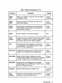
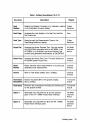
Table 1. Softkey Descriptions (4 of 17)
Key Name
Description
Chapter
Cal Int Srcs
Perform the routine to generate new VNOMS.
(Nominal voltages to set the HP 11848A Internal
Sources)
HP 3048A
Calibration
Manual
CAL Source
Configures the Calibration Source in the Source
Control Diagram
2 Meas.
Definitions
CAL
System
Enables generation of CALDATALO, CALDATAHl, and
VNOMS. Also enables the loading of storing of
calibration files.
5 Special
Functions
Calibr
Process
Accesses the menu for defining the measurement
calibration from the Measurement Definition display.
2 Meas.
Definitions
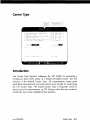
Carrier
Type
Allows you to select CW or PULSED carrier (Carrier
Type should normally be set to CW for non-pulsed
noise measurements).
5 Special
Functions
Center
Voltage
Increments the HP 11848A Tune Voltage Output in
50 mV steps for the Connect Diagram Display.
2 Meas.
Definitions
SHIFT
Center
Voltage
Decrements the Tune Voltage Output level.
Clear
Caldata
Sets the CALDATA in memory to zero.
5 Special
Functions
Clear
Outoflk
Resets the Out of Lock flip-flop and LED indicator on
the HP 11848A Interface. The Out of Lock condition
will only reset if the system is within the limits
required to maintain lock.
5 Special
Functions
Clear
Overld
Resets the Overload flip-flop and LED indicator on
the HP 11848A Interface. The Clear Overload will only
reset if it senses a non-damaging input single.
5 Special
Functions
Softkey Index
7
Table 1. Softkey Descriptions (5 of 17)
Description
Key Name
8
Chapter
Cmputd
Outputs
Accesses the additional formats for graphing the
measurement results.
3 Graphic
Functions
Control
Allows you to toggle between System Control (HP-IB)
and Manual Control for an instrument block in the
Source Control Diagram.
2 Meas.
Definitions
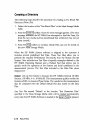
Create Dir
Enables you to create a file directory for Mass Media
Storage of Test Files or measurement Results Files.
This softkey only appears when an existing directory
cannot be found when trying to store a Test or
Result File.
2 Meas.
Definitions
CW
Refer to Carrier-Type softkey. (Not a softkey.)
5 Special
Functions
Dae Tests
Verifies each bit for the three DACs within the
HP 11848A Phase Noise Interface.
HP 3048A
Calibration
Manual
Data Type
Selects the Data Type for the Integration results.
(Integrated Noise)
4 Computed
Outputs
Deer. HPF
Decreases the HP 11848A High Pass Filter in the
Noise Monitor.
5 Special
Functions
Deer. LPF
Decreases the HP 11848A Low Pass Filter in the
Noise Monitor.
5 Special
Functions
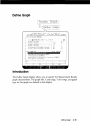
Define
Graph
Accesses the Graph Definition Display to enter the
graph parameters for the Results Graph.
2 Meas.
Definitions
Define
Msrmnt
Provides access to the five Measurement Definition
displays, the Test Files display, and the Parameter
Summary display.
2 Meas.
Definitions
Delete
Entry
Deletes the specified entry.
4 Computed
Outputs
Softkey Index
Table 1. Softkey Descriptions (6 of 17)
Key Name
Description
Chapter
Delete
fnstr.
Allows you to delete an instrument from the System
Configuration Table.
6 System
Configuration
Delete
Point
Removes a point form the Spec-Line Table in the
Define Graph display.
2 Meas.
Definitions
Detect
Const
Steps through the calibration methods available on
the Calibration Process display for calibrating the
Phase Detector Constant.
2 Meas.
Definitions
DONE
Returns operation to the previous display.
None
Down
Convert
Configures a Down Converter into the Source Control
Diagram. The System Control softkey is enabled for
this function when the HP 11729C is selected.
2 Meas.
Definitions
DUT
The Device Under Test configured in the Source
Control Diagram. This softkey allows you to define
the DUT for your measurement.
2 Meas.
Definitions
DUT Source
Configures the signal source in the Source control
Diagram for an FM Discriminator measurement.
2 Meas.
Definitions
Enter State
Similar to Send command softkey found under
11848A Control; however, switches are now changed
in the HP 11848A. (This is for a simulation only.)
5 Special
Functions
EFC/DCFM
Configures the Tune Voltage path in the Source
Control Diagram for the DCFM port or the EFC port
(Electronic Frequency Control).
2 Meas.
Definitions
Eval Allan
Solves the Allan Variance for Sigma of Tau.
4 Computed
Outputs
Eval.
Caldata
Accesses a routine that allows you to display the
response of a specific calibration path.
5 Special
Functions
Softkey Index
9
Table 1. Softkey Descriptions (7 of 17)
Description
Key Name
Eval intgrl
Chapter
Performs the computation to solve the Definite
Integral for the specified entries.
4 Computed
Eval Sigma
Performs the computation of Sigma of Tau for the
specified entries.
4 Computed
Outputs
FFT
Segmnts
Accesses the FFT Segment Table definitions.
5 Special
Functions
Fnctl. Chk.
Verifies HP 3048A functionality.
HP 3048A
Calibration
Manual
Freeze
Files
Moves the cursor from the Measurement Results
selection field to the computation results file labelling
field on the 3 Source Comparison display.
4 Computed
Outputs
Graph Type
Steps through the Graph Type Menu [S$(f), L(f),
S^(f) and Sy(f)] on the Define Graph display.
2 Meas.
Definitions
Hard Copy
Outputs the current display to the printer described in
the System Configuration table.
3 Graphics
Functions
SHIFT Hard
Copy
Outputs the parameter summary along with the
Results Graph and initiates a form feed.
HELP
Accesses operating information for the current display. None
ignore Out
of Lock
Refer to Test Mode softkey. (Not a softkey.)
5 Special
Functions
Integr
Noise
Allows integration of the total noise power between
two specified offset frequencies.
4 Computed
Outputs
Int. Adj'mnt.
Accesses routines to adjust the circuits in the
HP 11848A Phase Noise Interface.
HP 3048A
Calibration
Manual
10
Softkey Index
Outputs
Table 1. Softkey Descriptions (8 of 17)
Key Name
Description
Chapter
Instr.
Params
Accesses the display for entering the operating
parameters of the device being used in the
measurement.
2 Meas.
Definitions
Known File
Selects the Result File to be used as the reference
for 2 Oscillator Comparison. This file must be
computed from a 3 Oscillator Comparison.
4 Computed
Outputs
List Spurs
Performs the routine to list all marked spurs within
the measured data.
4 Computed
Outputs
Load Alt.
Loads and executes the 'Alternate Test System' file
from the Mass Storage Table.
6 System
Configuration
Load
Caldata
Loads the CALDATALO or CALDATAHI from the
specified Mass Storage Media specified.
5 Special
Functions
Load
Config
Loads the System Configuration Table.
6 System
Configuration
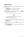
Load File
Loads the selected Test or Result file from the mass
storage media. The current file will be overwritten by
the new file.
2 Meas.
Definitions
Load Table
Loads the table of specific file locations.
6 System
Configuration
Lock Loop
Initiates routines in the Noise Monitor Mode to close
the PLL (Lock Loop). Verifies all of the system
checks to ensure that the sources are phase locked.
5 Special
Functions
SHIFT Lock
Loop
Toggles the Out of Lock flip-flop. If the sources are
within the specified Drift Tracking Range, the system
will reinstate the locked condition.
Manage
Caldata
Accesses a display which allows you to display the
response of a specific calibration path.
HP 3048A
Calibration
Manual
Softkey Index
11
Table 1. Softkey Descriptions (9 of 17)
Description
Key Name
Chapter
Marker
Enables the Marker Function.
3 Graphics
Functions
Marker 1
Moves marker onto raw data plot in the Evaluate Cal
Data display,
HP 3048A
Calibration
Manual
Marker 2
Moves marker onto curve fitted data plot.
HP 3048A
Calibration
Manual
Marker
3561A
Reads the marker on the HP 3561A Dynamic Signal
Analyzer for the Noise Monitor Mode and displays
the corrected levels and offset frequency on the
computer display.
5 Special
Functions
Marker
ON/OFF
Allows the addition of a Marker point on the Results
Graph.
3 Graphics
Functions
Marker
(RF
Analyzer)
Reads the marker on the RF Analyzer configured in
the system for the Noise Monitor Mode and displays
the corrected levels and offset frequency on the
computer display.
5 Special
Functions
Mass
Storage
Allows you to specify the mass storage location for
the HP 3048A data files.
6 System
Configuration
New
Msrmnt
Initiates a new measurement using the parameters
currently defined in the Measurement Definitions
displays. Selecting this softkey causes the HP 3048A
to complete the Measurement Calibration as defined
in the Calibration Process display before making the
Noise Measurement.
2 Meas.
Definitions
NewNse
Monitor
Performs a measurement calibration and then allows
real-time noise measurement of single points.
5 Special
Functions
12
Softkey index
Table 1. Softkey Descriptions (10 of 17)
Key Name
Chapter
Description
Next
Method
Selects the Detector Constant {K$) calibration method 2 Meas.
in the Calibration Process display.
Definitions
Next Page
Accesses the next display in the Help Text and the
File Directories.
None
Next Type
Steps through the Measurement Types in the
Type/Range definition display.
2 Meas.
Definitions
Noise Flat
Accesses the Noise Flatness Test. This test verifies
the CALDATAHI generated with an HP 3585A. If an
HP 3585A is not available, the Noise Flatness Test
corrects and generates modifications to CALDATAHI.
HP 3048A
Calibration
Manual
Noise Floor
Accesses the Noise Floor Test. This test verifies the
HP 3048A System Noise Floor.
5 Special
Functions
Noise
Monitor
Allows real-time noise measurements of a previously
calibrated noise measurement.
5 Special
Functions
Normal
Refer to Test Mode softkey. (Not a softkey.)
5 Special
Functions
Normalized
Bandwidths
Selects the plotted BW of the graphic display.
(Not a softkey.)
4 Computed
Outputs
Omit Spurs
Performs the computation excluding all marked spurs
for the specific entries.
4 Computed
Outputs
Option 1
Generates new CALDATA for all but the external
paths of the HP 11848A Phase Noise Interface.
HP 3048A
Calibration
Manual
Option 2
Generates new CALDATA for all of the HP 11848A
Phase Noise Interface paths.
HP 3048A
Calibration
Manual
Softkey Index
13
Table 1. Softkey Descriptions (11 of 17)
Key Name
Description
Chapter
Other Keys
Accesses the second set of graphics function keys.
3 Graphics
Functions
Param
Summary
Accesses the list of measurement setup and
calibration data for the current noise graph displayed.
Lists the measurement-defining parameters for the
measurement results currently in memory or loaded
from a Result File.
3 Graphics
Functions
Pert. Tests
Accesses the HP 3048A System Checks that verify
the performance of the HP 3048A.
HP 3048A
Calibration
Manual
Place DUTs
Configures the DUT in the Source Control Diagram
for the Phase Noise Without a Phase Lock Loop
measurement type.
2 Meas.
Definitions
Plot Data
Plots the noise data on the display without redrawing
the graticule. Useful for placing multiple noise traces
(loaded from the Result files) on a single graph.
3 Graphics
Functions
SHIFT Plot
Data
Plots the noise data currently in memory to an
external plotter.
Plot
ON/OFF
Causes the system to display the Measurement
Response of the HP 11848A circuit path as it is
characterized during system calibration.
HP 3048A
Calibration
Manual
Plotter
Pens
Accesses the plotter-pen specification menu from
System Config Table. This menu allows you to select
one of 8 colors for each of four pens.
6 System
Configuration
Plot w/o
Spurs
Plots the measured noise data currently in memory
without plotting the marked spurs. To display the data
3 Graphics
Functions
without spurs, you must first select the Redraw Graph
softkey then the Plot w/o Spurs softkey.
14
Softkey Index
Table 1. Softkey Descriptions (12 of 17)
Key Name
Description
Chapter
Preset
Presets the HP 11848A Interface to predefined
turn-on condition.
5 Special
Functions
Proceed
w/Adj.
Proceeds with the measurement using the adjusted
PLL suppression when an Accuracy Specification
Degradation has been detected.
8 Messages
Proceed
Theor.
Proceeds with the measurement using the theoretical
PLL suppression when an Accuracy Specification
Degradation has been detected.
8 Messages
Quadr
Method
Quadrature to be established by changing the source
frequency or by manual adjustment of the delay line
in the Source Control display.
2 Meas.
Definitions
PULSED
Refer to Carrier-Type softkey. (Not a softkey.)
5 Special
Functions
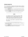
Read Dir.
Allows you to read the directory of Test or Result Files 2 Meas.
in the current mass media (disc).
Definitions
Recal
Spurs
Calibrates the spurs at the end of the Spur Accuracy
Performance Test.
HP 3048A
Calibration
Manual
Redraw
Graph
Redraws the noise graph on the display. Used for
redrawing the Results Graph, or other changes that
have been made in the Define Graph display.
3 Graphics
Functions
SHIFT
Redraw
Graph
Outputs graph to an external plotter.
Softkey Index
15
Table 1. Softkey Descriptions (13 of 17)
Key Name
Description
Chapter
Redraw
GraticI
Redraws the graph without noise data. Essentially
erases all plotted data from the graph.
SHIFT
Redraw
GraticI
Outputs graph to an external plotter.
Ref.
Source
Allows you to specify a reference source in the
Source Control Diagram. Accesses each RF Source
entered in the System Configuration Table and the
HP 11848A's internal sources.
2 Meas.
Definitions
Remove
Line
Erases the slope line that the cursor is positioned on.
3 Graphics
Functions
Repeat
Msrmnt
Initiates a measurement without performing a
measurement calibration. This should only be used
for measuring the same device or a similar device
with the same power level (±0,5 dB) at the same
frequency.
2 Meas.
Definitions
Results
Files
Accesses the Results File Directory. You may load or
store Results Files from this menu.
3 Graphics
Functions
RF
Segmnts
Accesses the RF Segment Tables. This special
function enables you to modify the Segment Tables
to enhance your measurement.
5 Special
Functions
Run Test
Initiates execution of the selected functional test.
HP 3048A
Calibration
Manual
Select
Detect.
Allows you to select one of three available phase
detector input ports of the HP 11848A from the
Define Graph display.
2 Meas.
Definitions
Select
Path
Allows selection of the signal path within the
HP 11848A to be characterized by the selected test.
HP 3048A
Calibration
Manual
16
Softkey Index
3 Graphics
Function
Table 1. Softkey Descriptions (14 of 17)
Key Name
Chapter
Description
Select Test
Allows selection of individual tests from the
Functional Test display.
HP 3048A
Calibration
Manual
Send
Command
Outputs the conditions displayed on the 11848
Control display to the HP 11848A interface.
5 Special
Functions
Set Clock
Sets the computer's real time clock.
6 System
Configuration
Set Line
Sets the slope line currently active on the graph.
3 Graphics
Functions
Sigma vs.
Tau
Allows computation of Sigma for the specified N, T,
Tau, and Stop frequency.
4 Computed
Outputs
Slope Lines
Allows you to place slope lines on the Results Graph.
3 Graphics
Functions
Sngl Path
Selects the signal path for the Functional Check.
HP 3048A
Calibration
Manual
Solve A,B.C
Initiates the Three Oscillator Comparison computation. 4 Computed
Outputs
Solve for B
Initiates the Two Oscillator Comparison computation.
4 Computed
Outputs
Source
Configures the source in the Source Control Diagram
for Phase Noise Without a Phase Lock Loop
measurement.
2 Meas.
Definitions
Source
Control
Accesses the Source Control Diagram for defining the
measurement set up and HP-IB control requirements.
2 Meas.
Definitions
Span
Increments the spans defined in the FFT and RF
Segment Tables for the Noise Monitor Mode.
5 Special
Functions
Softkey Index
17
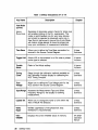
Table 1. Softkey Descriptions (15 of 17)
Key Name
Spcl.
Funct'n
Description
Recommended for advanced users only. Accesses
the HP 3048A's advanced operating functions.
Chapter
5 Special
Functions
• Modify the measurement segment definitions.
• Execute system performance verification and
calibration.
• Select the test mode.
• Modify the measurement process to support
measurement of pulsed carriers.
• Interactively control the internal configuration of
the HP 11848A Interface.
• Manipulate the system CAL DATA.
• Noise Monitor.
Spec Lines
Allows definition of specification lines in the Define
Graph display.
2 Meas.
Definitions
Spur Accy.
Verifies Spur Accuracy. This performance test verifies
the HP 3048A measurement accuracy to 550 kHz.
HP 3048A
Calibration
Manual
Spur List
Generates a list of all the spurs marked within the
measurement (up to 100 entries). This list can be
3 Graphics
Functions
output to a printer by selecting Hard Copy
Store
Caldata
Stores the CALDATALO or CALDATAHI from memory
to the mass storage media specified in the Mass
Storage Media File (System Configuration).
5 Special
Functions
Store
Config
Allows you to store the System Configuration Table
to the mass storage media specified in the mass
storage table.
6 System
Configuration
Store File
Stores a Test File or Result File.
2 Meas.
Definitions
Store Table
Stores the currently configured file directory.
6 System
Configuration
18
Softkey Index
Table 1. Softkey Descriptions {16 of 17)
Key Name
Description
Chapter
Suppr. Plot
Accesses the PLL Suppression Plot. This softkey
only appears when an Accuracy Specification
Degradation is detected. The PLL Suppression Plot is
automatically displayed when the Troubleshoot Mode
has been selected.
5 System
Configuration
System
Clock
Provides access to the systems real time clock.
6 System
Configuration
System
Config
Accesses the System Configuration Table. All
equipment to be controlled over the HP-IB interface
must be listed in this table.
6 System
Configuration
System
Preset
Allows you to reset the system hardware to its
predefined turn-on state. System preset loads the
Default data files and configures the HP 3048A to
make its demonstration measurement when the
New Measurement softkey is pressed.
None
Take Sweep
Initiates measurement of the span selected in the
Noise Monitor display.
5 Special
Functions
Test All
Selects all of the available tests.
HP 3048A
Calibration
Manual
Test Files
Accesses the Test File Directory. You may load or
store Test Files from this menu.
2 Meas.
Definitions
Test Mode
Allows selection of the Normal, Trouble Shoot, or
Ignore Out-of-lock mode.
5 Special
Functions
Normal
Default Test Mode; PLL suppression is not plotted
unless an accuracy specification degradation of
> 1 d B is measured.
Trouble
Shoot
Enables plotting of the PLL suppression during its
characterization and provides access to 11848A
Control at the Connect Diagram and other displays.
(cont'd)
Softkey Index
19
Table 1. Softkey Descriptions (17 of 17)
Description
Key Name
Chapter
Test Mode
(cont'd)
Ignore
Out-of-lock
Bypasses all automatic system checks for phase lock
and enables plotting of the PLL suppression. This
mode is recommended only for very noisy devices
and should be selected by advanced users only. A
New Msrmnt performed in Ignore Out-of-lock Mode
will make a single attempt to close the phase lock
loop upon completion of measurement calibration.
Time Base
Allows you to define the Time Base connection for
sources in the Source Control Diagram.
2 Meas.
Definitions
Toggle LNA
Allows LNA to be switched In or Out when a pulsed
carrier type is selected.
5 Special
Functions
Trouble
Shoot
Refer to Test Mode softkey
5 Special
Functions
Tuning
Const
Steps through the calibration methods available on
the Calibration Process display for calibrating the
VCO Tuning Constant.
2 Meas.
Definitions
Tune
Voltage
Allows you to define the Tune Voltage path for the
VCO source in the Source Control diagram.
2 Meas.
Definitions
Type/Range
Accesses the Measurement Type and Offset
Frequency Range for the display for defining
measurement.
2 Meas.
Definitions
Update Dir.
Allows you to change the name of a file within the
Test or Result File directory.
2 Meas.
Definitions
Verify
Suppr
Verifies suppression of the phase lock loop.
Verification is recommended.
2 Meas.
Definitions
View
VNOMS
Displays the current VNOMS values in memory.
HP 3048A
Calibration
Manual
20
Softkey Index
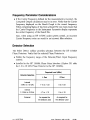
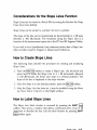
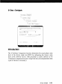
General Information
Introduction
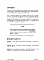
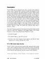
The HP 3048A Phase Noise Measurement Reference Manual is designed
to aid you in understanding and performing the HP 3048A measurement
techniques and its advanced features. Within this chapter is the general
information that describes the HP 3048A and its support services.
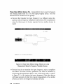
HP 3048A Description
pg. 1-2
Documentation Updating
pg. 1-4
Software Updating
pg. 1-5
Guide to System Flexibility
pg. 1-7
HP 3048A System and Option Specifications
pg. 1-11
General information
1-1
HP 3048A Description
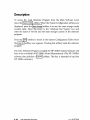
What is the HP 3048A?
The HP 3048A provides you a standard process for measuring phase noise.
It allows you to measure sources of many types with a flexible system
configuration.
The HP 3048A Phase Noise Measurement System includes:
• The HP 11848A Phase Noise Interface, an interface box specifi
cally designed for high performance phase noise measurements. The
HP 11848A supports several measurement techniques for phase noise
and AM noise measurement. Built in to the interface are phase de
tectors, amplifiers, filters, and switches necessary to measure phase
noise over a frequency range of 5 MHz to 18 GHz. An input for an
external phase detector outside the above mentioned frequency range
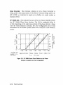
is also provided. Internal sources are provided to allow the system to
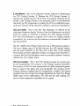
functionally check all of its signal handling circuits insuring proper
operation prior to making a measurement.
• The HP 3561A Dynamic Signal Analyzer, a Fast Fourier Transform
analyzer of a wide frequency range (125 fiHz to 100 kHz). The
HP 3561A has built-in data averaging capabilities, large dynamic
range, and fast measurement speed which make it ideal for quantifying
demodulated phase noise (noise voltages).
• Measurement software, a program that includes all drivers necessary
to run both standard and optional instruments of the HP 3048A
system.
• Operator's Training, an operator's training course that explains all of
the operating modes and measurement techniques of the HP 3048A,
when each technique is appropriate, and how to analyze the measured
data.
1-2
General Information
What is the HP 3048A Used For ?
The HP 3048A is designed to reduce the difficulty of making accurate
phase noise measurements. The HP 3048A allows you to make phase
noise measurements using a phase detector in a phase lock loop con
figuration, a phase detector without a phase lock loop, or with an FM
discriminator.
Each method allows the measurement results to be plotted as phase noise
{£(/) or S$(f)), or frequency noise (Sy(f) or Sv(f)) over an offset range
of 1 mHz to 100 kHz (or to 40 MHz with a supported RF Analyzer).
Using an external crystal detector, the HP 3048A system can automat
ically quantify the level of AM noise that could affect a phase noise
measurement.
The HP 3048A allows you to measure and plot the results of Noise Voltage
measurements.
A real-time measurement mode (Noise Monitor) is available for monitor
ing single frequency points, or changes in the level of phase noise and
discrete spurs as changes are made to the device-under-test.
The system also allows you to plot measured data (Computed Outputs) as:
• Integrated Noise,
• Sigma vs Tau (Allan Variance),
• Various Normalized Bandwidths,
• 2 or 3 Oscillator Comparisons,
• Spur Listings.
Genera! Information
1-3
Documentation Updating
A "MANUAL UPDATES" packet is shipped with the manual when
changes to the manual are necessary to provide the most current informa
tion about the product available at the time of shipment. These packets
consist of replacement and addition pages which should be incorporated
into the manual to bring it up to date.
Hewlett-Packard offers a Documentation Update Service that will provide
you with further updates as they become available. If you plan to
operate or service HP 3048A's with different serial prefixes, we strongly
recommend that you join this service immediately to ensure that this
manual is kept current. For more information, refer to the Documentation
Update Service reply card included in this manual.
1-4
General Information
Software Updating
Software is a significant part of the HP 3048A Phase Noise System
Hewlett-Packard offers two levels of software support services for the
HP 3048A, the Software Material Subscription, and the Software Noti
fication Service.
Software Material Subscription
Software Materials Subscription (SMS) ensures that your software is never
out-of-date. SMS automatically provides you with update changes to your
HP software as they are released.
When you purchase an SMS contract, you will receive the following
materials:
• New Software Releases
• Software Status Bulletins
• Software Release Bulletins
• Documentation Updates
Software Notification Service
Software Notification Service (SNS) keeps you up-to-date with the latest
changes to your software and informs you when new software releases
will be available.
When you purchase an SNS contract, you will receive the following
materials:
• Software Status Bulletin
• Software Release Bulletin
General Information
1-5
New Software Releases
With SMS you will automatically receive all software releases for the
HP 3048A as they become available. These releases may provide increased
software performance and capability, or the resolution of specific anoma
lies. You will also receive all pertinent information necessary to ensure a
smooth transition to the new software revision.
Software Status Bulletin
With either SMS or SNS you will receive the Software Status Bulletin
(SSB). The Software Status Bulletin (SSB) contains timely information on
reported discrepancies in HP software and documentation, and temporary
correction or workaround information.
Software Release Bulletin
The Software Release Bulletin (SRB) is provided with both the SMS and
the SNS. When a new software release is made for the HP 3048A, all
problems that were corrected in that release are reported in the Software
Release Bulletin. The problem is then removed from the SSB.
Documentation Updates
You will receive Documentation Updates automatically when you pur
chase an SMS contract.
1-6
General Information
Guide to System Flexibility
The HP 3048A can be configured many different ways to optimize its
operation for specific applications. All configurations of this system must
include the HP 3048A's basic components and a desktop computer to be
operational. The following guide will help you match your applications to
the optimum system configuration.
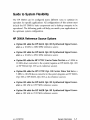
HP 3048A Reference Source Options
• Option 001 adds the HP 8662A Opt. 003 Synthesized Signal Gener
ator as a 10 kHz to 1280 MHz reference source.
• Option 002 adds the HP 8663A Opt. 003 Synthesized Signal Gener
ator as a 10 kHz to 2560 MHz reference source
• Option 003 adds the HP 11729C Carrier Noise Test Set as a 5 MHz to
18 GHz down converter to the system (requires an HP 8662A Opt. 003
or HP 8663A Opt. 003 as its reference source).
• Option 004 adds the HP 11729C Opt. 130 Carrier Noise Test Set as a
5 MHz to 18 GHz down converter to the system (requires an HP 8662A
Opt. 003 or HP 8663A Opt. 003 as its reference source).
• Option 005 adds the HP 8642A Opt. 001 Synthesized Signal Gener
ator as 100 kHz to 1057 MHz reference source.
• Option 006 adds the HP 8642B Opt. 001 Synthesized Signal Gener
ator as 100 kHz to 2115 MHz reference source.
rev.05SEP89
General Information
1-7
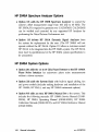
HP 3048A Spectrum Analyzer Options
• Option 101 adds the HP 3585B Spectrum Analyzer to extend the
system's offset measurement range from 100 kHz to 40 MHz. The
HP 3585A/B is required to generate new CALDATAHI. CALDATAHI
can be verified and corrected by any supported RF Analyzer by
performing the Noise Flatness Performance test.
• Option 110 deletes HP 3561A Dynamic Signal Analyzer from
the system for replacement by the user. (The HP 3048A will not
operate without the HP 3561 A. Option 110 allows a customer-owned
HP 3561A to be integrated into the HP 3048A system. The HP 3561A
must meet its specifications for the HP 3048A system specifications to
be warranted.)
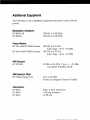
HP 3048A System Options
• Option 201 adds the 1.6 to 18 GHz Phase Detector to the HP 11848A
Phase Noise Interface for microwave phase noise measurements
without a down converter.
• Option 202 adds the System Rack with built-in signal cabling, fan
and power module (includes racking hardware and installation of the
HP 11848A, HP 3561A, and any HP 3048A instrument options).
• Option 910 adds an extra HP 3048A Manual Set to the system. This
includes the following manuals: HP 11848A Service Manual (1184890004), HP 3048A Operating Manual (03048-90001), HP 3048A
Calibration Manual (03048-90015), and HP 3048A Reference Manual
(03048-90002).
1-8
General Information
rev.05SEP89
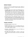
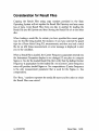
Desktop Computers
Computers used with the HP 3048A system must have a BASIC 5.0
Operating System, and a minimum of 3 Mbytes of RAM to operate the
HP 3048A software.
• HP 98580B, Options ABA and 008, Series 300 Measurement Au
tomation System includes 1 Mbyte of RAM. An HP 46083A HPHIL Knob should also be ordered with this computer to control the
HP 3048A graphics marker. Alternatively an HP 98203C Keyboard
with a built-in knob may be ordered. Order Option 05A to delete
the standard keyboard, and then order the HP 98203C Keyboard
separately. (Order HP 98257A, 1 Mbyte RAM Cards to add memory.)
• HP 9836S, Option 001, Series 200 Desktop Computer Option 001
provides 1 Mbyte of RAM. A 31 fa-inch external disc drive such as the
HP 9122D or the HP 9153A Winchester disc drive is required with the
HP 9836S Series 200 Desktop Computer. (Order HP 98257A, 1 Mbyte
RAM Cards to add memory.)
Computer Accessories
• HP 98203C Keyboard with built-in knob.
• HP46083A HP-HIL Knob needed by the HP 98580A Desktop Com
puter to control the graphics marker of the HP 3048A (not needed if
the HP 98203C Keyboard is ordered).
• HP 98257A 1 Mbyte RAM Card used with the HP 98580A and
HP 9836A Desktop Computers.
• HP 10833B 2-meter HP-IB Cable one required to connect each
computer, printer, spectrum analyzer, or disc drive to the HP 3048A
system.
General Information
1-9
Disc Drives
• HP 9122D Dual Disc Drive for 31/2-inch flexible discs.
• HP 9153A 10 Mbyte Winchester Disc Drive with a built-in 3 y 2 - m c h
flexible disc drive.
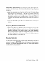
Spectrum Analyzers
The addition of any of the following Spectrum Analyzers extends the
offset range to 40 MHz.
• HP 3585A/B 20 kHz to 40 MHz Spectrum Analyzer provides Track
ing Generator output needed to generate CALDATAHI for calibration
of the HP 3048A from 100 kHz to 40 MHz. (All supported spectrum
analyzers can be used to verify or modify CALDATAHI.)
• HP 8562A 1 kHz to 22 GHz Spectrum Analyzer
• HP 8568A/B 100 Hz to 1500 MHz Spectrum Analyzer
• HP 8567A 1 kHz to 1500 MHz Spectrum Analyzer
• HP 8566A/B 100 Hz to 22 GHz Spectrum Analyzer
• HP 71100A 100 Hz to 2.9 GHz Spectrum Analyzer
• HP 71200A 50 kHz to 22 GHz Spectrum Analyzer
Printers/Plotters
• HP 2225A Thinkjet Printer for plotting graphs and documenting tests.
1-10
General Information
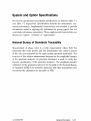
System and Option Specifications
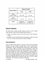
The System specifications and Option specifications are iisted in Table 1-1
and Table 1-2 respectively. Specifications describe the instrument's war
ranted performance. Supplemental characteristics are intended to provide
information useful in applying the instrument by giving typical, but not
warranted performance parameters. These supplemental characteristics are
denoted as "typical," "nominal," or "approximate."
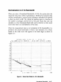
National Bureau of Standards Traceability
Measurement of phase noise is a ratio measurement where both the
numerator (the noise power) and the denominator (the carrier's power)
of the ratio are measured by the same system spectrum analyzer(s). The
accuracy of this relative measurement depends on the amplitude linearity
of the spectrum analyzer. (A precision attenuator is used, to verify the
linearity specification of the spectrum analyzer.) The amplitude linearity
calibration of the spectrum analyzer is be traceable to the National Bureau
of Standards (NBS) if the precision attenuator and other instruments used
to perform the calibration are traceable to NBS.
rev.05SEP89
General Information
1-11
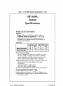
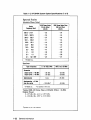
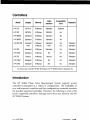
Table 1-1. HP 3048A System Specifications (1 of 4)
HP 3048A
System
Specifications
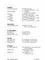
PHASE DETECTOR PORTS
Frequency
Range: 5 MHz to 1.6 GHz (low-frequency inputs)
Additional Range with Option 201: 1.2 to 18 GHz
(high-frequency inputs) (The frequency range can be
extended with a customer-supplied phase detector or
frequency discriminator.)
Amplitude
Low-Frequency inputs
Maximum Signal (dBm)
Minimum Signal (dBm)
High-Frequency Inputs
Lin
R in
Lin
H in
+23
+15
+23
+0
+10
+7
+5
+0
Offset Frequency Range
0.01 Hz to 40 MHz for carriers from 95 MHz to 18 GHz
0.01 Hz to 2 MHz for carriers from 5 MHz to 95 MHz
(Assumes addition of 40 MHz spectrum analyzer to the
system, otherwise offset range limited to 100 kHz.)
Accuracy (measurement of all noise and spurious present at
the two inputs to the phase detector and system
contribution):
±2 dB for 0.01 Hz to 1 MHz offsets
±4 dB for 1 MHz to 40 MHz offsets
In order for the HP 3048A to meet its accuracy specifications,
the following qualifications must be met:
• Source return loss >9.5 dB (<2 : 1 SWR)
• Source harmonic distortion < - 2 0 dB (or a square wave)
• Nonharmonic spurious, except for phase modulation close to
the carrier, <—26 dBc
1-12
General Information
rev.05SEP89
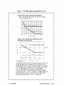
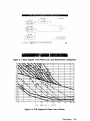
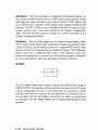
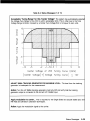
Table 1-1. HP 3048A System Specifications (2 of 4)
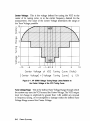
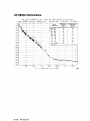
System Phase Noise and Spurious Responses
(Does not include phase noise and spurious signals
from a reference source.)
-60
-80
-100
-120
-140
-160
1 1
-180
0.01
0 1
1
10
100
1k
10k
100k
1M
10M 40M
Offset Frsquency (Hzl
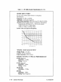
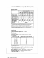
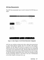
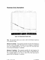
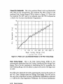
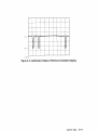
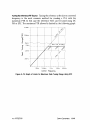
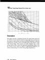
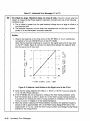
System Noise and Spurious Response Increase
with Input Level Decrease
*2B
L Input signal:&+L5 dBM Lou Frequency Input
£+7 dSM Loin Frequency Input
m
□
0
"O
C
L
U
n
B
/
«S
High Frequency Input
Amp! Itude Range
+IB
*15
+2B
*2S
R Input Signal Level (dBm)
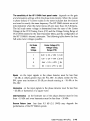
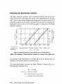
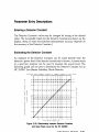
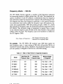
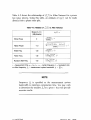
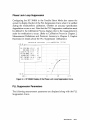
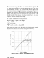
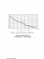
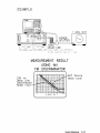
To determine system noise and spurious response levels, find
the dB degradation at the signal input level from the lower
graph and add to the curves of the upper graph. For example,
if a +15 dBm signal is applied to the Low Frequency L Input
and a +5 dBm signal to the R Input, the degradation is
+10 dB. Therefore, the specified maximum spurious signal
level increases from - 1 1 2 to - 1 0 2 dBc at all offset frequencies
and the system's maximum noise level at >10kHz offset
frequencies increases from - 1 7 0 to - 1 6 0 dBc/Hz.
rev.05SEP89
General Information
1-13
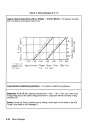
Table 1-1. HP 3048A System Specifications (3 of 4)
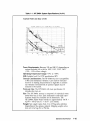
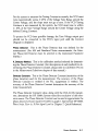
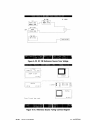
NOISE INPUT PORT
(For use with externa! phase detector or frequency
discriminator)
Frequency: 0.01 Hz to 40 MHz
Amplitude: 1 Volt peak maximum
Typical Input Impedance: 50fl; return loss >9,5 dB {<2:1 SWR)
Accuracy: External phase detector or frequency discriminator
measurements calibrated with ±1 dB accurate signals.
±2 dB for 0.01 Hz to 1 MHz offsets
±4 dB for 1 MHz to 40 MHz offsets
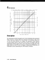
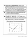
System Noise and Spurious Responses
Spurious Responses (dBnil
-100
-'20
—-
^\J 1 1
ISO
i()i
0 1
'
'0
100
'. k
! 0k
100k
1M
1 DM 40M
O^seT Frequency -.dz\
TUNING VOLTAGE OUTPUT
Voltage Range: ±10 volts
Current: ±20 mA maximum
Output Impedance: 50S2 nominal
SOURCE OUTPUT TYPICAL PERFORMANCE
10 MHz Source A
Amplitude: +15 dBm
Tuning: ±100 Hz
10 MHz Source B
Amplitude: -1-6 dBm
Tuning: ± 1 kHz
350-500 MHz
Amplitude: +17 dBm
400 MHz
Amplitude: - 5 dBm
Tuning: Fixed Frequency
1-14
General Information
rev.05SEP89
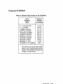
Table 1-1. HP 3048A System Specifications (4 of 4)
Typical Noise and Spur Levels
Power Requirements: Between 190 and 900 VA depending on
options included; 48 to 66 Hz; 100V, 110V, 220V, 240V
(+5%, - 1 0 % of line voltage)
Operating Temperature Range: +0°C to +55°C
EMI: Satisfies level B of VDE specification 0871
General Considerations: The HP 3048A has low susceptibility
to RFI and mechanical vibration. Care must be exercised
however in making measurements in high RFI or mechan
ical vibration environments as spurious signals may be
induced in the system.
Warm-up time: The HP 3048A will meet specification 20
minutes after turn-on.
Size: The HP 3048A system is composed of individual instru
ments that vary in size. Each instrument's individual speci
fications should be consulted for its dimensions. The
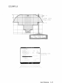
HP 11848A Phase Noise Interface is approximately 146 H X
425 W X 593 D cm (5.7 X 16.8 X 23.3 inches).
Weight: Net weight varies from 31 to 275 kg (68 to 603 lbs)
depending on the options ordered. Shipping weight varies
from 42 to 347 kg (93 to 758 lbs).
General Information
1-15
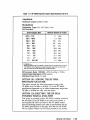
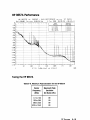
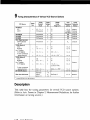
Table 1-2. HP 3048A System Option Specifications (1 of 9)
HP 3048A
Option
Specifications
The HP 3048A can be ordered with any of several optional
signal generators as a reference source for phase noise meas
urements. The following specifications address system opera
tion with these signal generators. The data that follows is in
addition to that given previously under the heading of
HP 3048A System Specifications. Refer to the data sheet for
each signal generator for more complete information on each
model.
OPTIONS 001 OR 002: ADDING THE HP 8662A
OR 8663A SIGNAL GENERATOR
The following data applies only if either the HP 8662A Opt.
003 or 8663A Opt. 003 is used as the reference source to
demodulate the test signal.
Frequency
Range: 100 kHz to 1280 MHz (to 2560 MHz with HP 8663A).1
Resolution: 0.1 Hz, 0.2 Hz: 640 to 1280 MHz, 0.4 Hz above
1280 MHz.
Accuracy and Stability (internal 10 MHz quartz oscillator):
Aging rate <5 X 10~ 10 /day after 10-day warm-up (typically
24 hrs in normal operating environment).
EFC: Provides a drift tracking range of ±10 - 8 with no degrada
tion of phase noise or spurious.
Measurements <5 MHz require external phase detector.
1-16
General Information
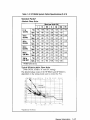
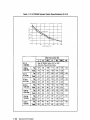
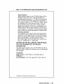
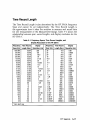
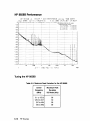
Table 1-2. HP 3048A System Option Specifications (2 of 9)
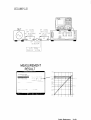
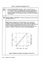
Spectral Purity 2
Absolute Phase Noise
Offset from Carrier (Hz)
1
10
100
1k
10k
100k
1M
-145
0.1 to
120 MHz
Typ.
-78
-108
-126
-132
-138
-139
Spec.
-68
-98
-116
-126
-132
-133
120 to
160 MHz
- 7 6 , -106
-125
-135
-148
-148
Spec.
-66
-96
-115
-129
-142
-142
160 to
320 MHz
Typ.
-70
-100
-119
-130
-142
-142
Spec.
-60
-90
-109
-124
-136
-138
320 to
640 MHz
Typ.
-64
-94
-114
-125
-136
-136
Spec.
-54
-84
-103
-118
-131
-132
Typ.
-58
-88
-108
-119
-130
-130
Spec.
-48
-78
-97
-112
-124
-126
Typ.
-52
-82
-102
-113
-124
-124
Spec.
-42
-72
-92
-106
-118
-120
Typ.
640 to
1280 MHz
1280 to
2560 MHz*
-150
-148
-145
-140
-134
* HP 8663A Option 003 only.
Typical HP 8662A/8663A Phase Noise
(With DCFM, 10 MHz "A" and EFC tuning)
The absolute phase noise of the HP 8662A and HP 8663A is
dependent on the tuning mode used to control the PLL.
:hp!P
3B4aW
Ca
4B.E>6
Hz
23
lir
:S98
iB:?G:35
13:32:40
^ Specified only with FM off.
General Information
1-17
Table 1-2. HP 3048A System Option Specifications (3 of 9)
Spurious Signals
Frequency Range (MHz)
0.1 to 120 to 160 to 320 to 640 to 1280 to
320
640
1280
2560
120
160
Spurious nonharmonicafly related1
-90
dBc
-100
dBc
-96
dBc
-90
dBc
-84
dBc
-78
dBc
Subharmonically re
lated (1/2, 3f/2, etc.)
none
none
none
none
-70 2
dBc
-40
dBc
Power line (60 Hz)
related to microphonically generated
(within 300 Hz)3
-90
dBc
-85
dBc
-80
dBc
-75
dBc
-70
dBc
-65
dBc
Harmonics
<30 dBc
1
In the remote mode it is possible to have microprocessor clock-related spurious
signals spaced 3 MHz apart at an absolute level ot typically less than -145 dBm.
2
3/2 spurs not specified for HP 8662A carrier frequencies above 850 MHz.
^ At a 50 Hz line frequency, powerline or microphonicaily related spurious signals may
be up to 3 dB higher and appear at offsets as high as 1 kHz from the carrier.
Amplitude
Typical Maximum Output Level: +16 dBm
Modulation
Modulation Types: FM, AM (Pulse with the HP 8663A)
FM Deviation
Center Frequency (MHz)
Maximum Peak Deviation dc FM (kHz)
0.1 - 1 2 0
120-160
160 - 320
320 - 640
640-1280
1280-2560*
100
25
50
100
200
400
'HP B663A Option 003 only
Indicated FM Accuracy: ±8% (7% for HP 8663A) of reading
plus 10 Hz (50 Hz to 20 kHz rates).
Input Impedance: HP 8662A: lkfi nominal, HP 8663A: 600fi.
Maximum Input Level: IV peak for specified accuracy.
Temperature Range: +15° to 35°C.
1-18
General Information
Table 1-2. HP 3048A System Option Specifications (4 of 9)
OPTIONS 003 OR 004: ADDING THE HP 11729C
OR 11729C OPT 130 CARRIER NOISE TEST SET
The following data is applicable to using the HP 11729C to
downconvert the test signal to an IF of between 5 MHz and
1280 MHz for subsequent demodulation using the Low
Frequency phase detector of the HP 3048A system, The
HP 8662A Opt. 003 or 8663A Opt. 003 Signal Generators
provide a 640 MHz reference signal for this downcoversion
process. These signal generators also provide a signal of
between 5 MHz to 1280 MHz to demodulate the
downconverted IF noise. The specifications that follow assume
this measurement set-up is used.
Input Requirements
Frequency
Measurement Frequency Range: 5 MHz to 18 GHz in 8
bands, excluding ±5 MHz around band center frequencies.
Band Center Frequencies: 1.92 GHz, 4.48 GHz, 7.04 GHz,
9.60 GHz, 12.16 GHz, 14.72 GHz, 17.28 GHz.
Amplitude
For carrier frequencies <1.28 GHz: - 5 dBm minimum to
+23 dBm maximum.
For carrier frequencies >1.28 GHz: +7 dBm minimum to
+20 dBm maximum.
Measurement Specifications
Offset Frequency Range
For carriers between 5 and 95 MHz from band centers:
0.01 Hz to 2 MHz.
For carriers >95 MHz from band center: 0.01 Hz to
40 MHz.
(Assumes addition of 40 MHz spectrum analyzer to the
system, otherwise offset frequency range limited to
100 kHz.)
System Noise Floor3
Absolute System Noise Floor (dBc/Hz), when used with the
HP 11729C and HP 8662A Option 003 or HP 8663A Option
003 as the reference source, phase locking via the signal
generator's EFC.
3
Specified only with FM off.
General Information
1-19
Table 1-2. HP 3048A System Option Specifications (5 of 9)
-20
-40
*
s
-60
f
-80
V
^
N^ X
Specification
N,
1
1
100
Typical
" s ^ .
120
140
180
1
10
100
1k
lot
Offset Frequency (Hz)
100k
IM
10M
Offset from Carrier (Hz)
1
0.1 to
1280 MHz
100
1k
10k
100k
1M
-140
See HP 3048A Option 001 or 002,
Absolute Phase Noise table,
1280 to
3200 MHz
Typ.
-53
-83
-103
-115
-129
-130
Spec.
-43
-73
-93
-108
-124
-126
3.2 to
5.76 GHz
Typ.
-47
-77
-97
-109
-127
-130
Spec.
-37
-67
-87
-104
-123
-126
5.76 to
8.32 GHz
Typ.
-43
-73
-93
-105
-125
-129
Spec.
-33
-63
-83
-100
-121
-125
8.32 to
10.88 GHz
Typ.
-40
-70
-90
-102
-123
-129
Spec.
-30
-60
-80
-97
-119
-125
10.88 to
13.44 GHz
Typ.
-38
-68
-88
-100
-122
-128
Spec.
-28
-58
-78
-95
-118
-125
Typ.
-37
-67
-87
-99
-121
-127
Spec.
-27
-57
-77
-94
-116
-124
Typ.
-35
-65
-85
-97
-119
-127
Spec.
-25
-55
-75
-92
-115
-123
13.44 io
16.0 GHz
16.0 to
18.0 GHz
1-20
| 10
General Information
-138
-135
-134
-132
-131
-129
Table 1-2. HP 3048A System Option Specifications (6 of 9)
System Spurious
System spurious signals in the HP 3048A Options 003 or
004 arise in three ways. First, from the detection and
baseband signal processing, <—104 dBc for offsets greater
than 0.2 Hz from the carrier. Second, any line-related or
other spurious signals on the HP 8662A or 8663A outputs
are translated to the noise spectrum output. Third, the
downconversion process gives rise to system spurious
signals whose frequency and level are determined by the
relation between the test signal frequency and the band
center frequency. The presence of system spurious signals
does not affect the typical measurement of random noise.
AM Noise Detection
The HP 3048A can be used for AM noise measurements
using either an external AM detector or the AM detector
built-in to the HP 11729C Option 130 (ordered as Option
004 of the HP 3048A). AM measurements with the
HP 11729C Option 130 can be made with a typical sensi
tivity of - 1 6 5 dBc/Hz at a 1 MHz offset.
OPTION 005 OR 006: ADDING THE HP 8642A
OPT. 001 OR 8642B OPT. 001 SIGNAL
GENERATOR
The following data applies only if the HP 8642A Opt. 001 or
8642B Opt. 001 is used as the reference source to demodulate
the test signal.
Frequency
Range: 100 kHz to 1057.5 MHz (to 2115 MHz with the
HP 8642B)*
Opt. 001 Stability: <10" 9 /day aging after 8 days warm-up.
'Measurements <5 MHz require extemai phase detector.
General Information
1-21
Table 1-2. HP 3048A System Option Specifications (7 of 9)
Spectral Purity
Absolute Phase Noise 5
Carrier
Frequency Band
SSB Phase Noise
20 kHz ONset
dBc/Hz
SSB Phase Noise Floor
200 kHz Offset
dBc/Hz
-125
-134
-137
-141
-144
-134
-144
-144
-144
1057.5-2115*
528.7 - 1057.5
264.3 - 528.7
132.1 - 264.3
66.0- 132.1
33.0 - 66.0
16.5 - 33.0
8.2 16.5
4.1 8.2
0.1 4.1
0.1 - 132.1 HET
-145
-146
-147
-148
-137
-125
-145
-145
-147
-148
-149
-138
-137
* HP 8642B only.
Spurious
Type of Spurious
0.1 to 1052.5 MHz
1057.5 to 2115 MHz1
Harmonics
Output Level <+10 dBm
Output Level <+16 dBm
- 3 0 dBc
- 2 0 dBc
- 2 5 dBc
- 2 0 dBc
Subharmonics
Nonharmonics, >10 kHz
from the carrier
1
HP8642B only.
none
- 4 5 dBc
-100 dBc2
- 9 4 dBc
' Not specified in HET oand.
T y p i c a l SSB A M Noise Floor at 200 k H z Offset, +16 d B m
O u t p u t Power:
< - 1 5 7 d B c / H z , 4.13 to 1057 M H z
< - 1 5 0 d B c / H z , 1057 to 2115 M H z
specified only for de FM <200 kHz.
1-22
General Information
Table 1-2. HP 3048A System Option Specifications (8 of 9)
Amplitude
Maximum Output Level:>16 dBm.
Modulation
Modulation Types: FM, AM, Phase, Pulse
FM Deviation
Carrier Frequency Band
1057.5 5287 264.3132.1 66.033.0 16.5 8.2 4.1 0.1 0.1 1
1
21151
1057.5
528.7
264.3
132.1*
66.0'
33.02
16.5*
8.2*
4.1*
132.1 HET
Maximum Deviation tic Coupled
3
1.5
750
375
187
MHz
MHz
kHz
kHz
kHz
93.8
46.9
23.4
11.7
kHz
kHz
kHz
kHz
93.8
1.5
kHz
MHz
HP8642Boniy.
Maximum deviation may be increased up to that shown for the HET band (0.1 MHz to
132.1875 MHz carrier frequency) by selecting deviation larger than the vafue shown
here. HET band can also be selected with the special function.
FM Accuracy, Rates <100 kHz: ±(5% of setting + 10 Hz).
Typical Input Impedance: 600ft nominal.
Maximum Input Level: IV peak.
OPTION 101: ADDING THE HP 3585A
SPECTRUM ANALYZER
This option extends the offset measurement range of the
HP 3048A from 100 kHz to 40 MHz. All of the HP 3048A
specifications dependent on an offset measurement range from
100 kHz to 40 MHz are valid with this option.
OPTION 110: DELETING THE HP3561A
DYNAMIC SIGNAL ANALYZER
This option is provided to allow HP 3561A's already owned by
the purchaser of the HP 3048A to be used in the system. A
user-supplied HP 3561A included in the HP 3048A system
must be operating properly and meet its specifications for the
HP 3048A specifications to be valid. Note that the HP 3048A
will not operate without an HP 3561A included in the system.
General Information
1-23
Table 1-2. HP 3048A System Option Specifications (9 of 9)
COMPATIBLE SPECTRUM ANALYZERS
The HP 3048A is designed to use several Hewlett-Packard
spectrum analyzers to extend the offset range from 100 kHz to
40 MHz. Those spectrum analyzers include the HP 3585A
(orderable as Option 101 to the HP 3048A), the HP 8562A/B,
8566A/B, 8567A, 8568A/B, 71100A, and 71200A. Automatic
control of each of these spectrum analyzers is provided. The
HP 3048A specifications apply fully when these compatible
spectrum analyzers are included in the system as long as the
spectrum analyzer is operating properly and meets its perform
ance specifications.
OPTION 201: ADD HIGH FREQUENCY PHASE
DETECTOR
This option adds a 1.2 to 18 GHz phase detector to the
HP 3048A to extend the carrier frequency of the test signals
that can be demodulated without prior downconversion by the
system. All of the HP 3048A specifications dependent on a
carrier frequency range from 1.6 to 18 GHz are valid with this
option.
OPTION 202: ADD SYSTEM RACK
This option provides the HP 3048A system and its options
installed in a full size instrument rack, Rack includes a power
module, all necessary signal cabling, and a pull-out shelf to
use as a work surface, Outside dimensions are approximately
163 H X 61 W X 81 D cm (64 X 24 X 32 inches). The net
weight varies from 191 to 275 kg {418 to 603 lbs.) depending
on the options installed. Shipping weight varies from 248 to
347 kg (543 to 758 lbs),
1-24
General Information
Visrm
Measurement Definitions
Introduction
The Measurement Definition is the process of defining the measurement.
This section describes the processes involved when the Define Msrmnt
softkey is selected.
Type/Range
pg. 2-3
Instrument Parameters
pg. 2-13
Calibration Process
pg. 2-41
Source Control
pg. 2-101
Define Graph
pg. 2-115
Test Files
pg. 2-119
Measurement Definitions
2-1
Type/Range
Define
Msrmnt
~ype/Range
MEflSUREMENF TYPE AND FREWNCY RANGE SPECIFICATION
MFFKUREMENl r ' F ' t :
hase Noise Using a Phase Lock Loop
Phase- N.-isis HsHuul Ubiny d PLL
Phase Noibc iJbinj an FM LUSM n i K i a k
HM N:;i=e. No;se Measur^EIPJIt ■Js,i-.r) H P V t t n "-nI>
ftiirn
t.-. ■MFq-JJF.FHFFr r F F ' N I T I f ' N '
nrr".rr FRE^UENO' RnMf,r:
FMTFR THF Fill I fiHItl"...
Mverajr=,..
iWr.rital-1,-
! . - : - : : !(- :G.E-
\ ='r
Introduction
The Type/Range display enables you to define:
• The type of measurement you wish to make,
• The frequency offset span you wish to measure, and
• The minimum number of measurements you wish to have taken for
averaging the noise in each segment of the offset span.
Type/Range 2-3
Measurement Type
To select the correct type of measurement, you need to determine the type
of noise to be measured and then the technique that best suits the device
and available hardware.
Noise measurements can be categorized as either:
• Phase Noise Measurements,
• AM Noise Measurements, or
• Baseband Noise Measurements.
Press the Next Type softkey to position the inverse video window at the
type of measurement you wish to perform.
NOTE
The Measurement Type that you specify will determine
which parameter entry fields appear in the remaining
Measurement Definition displays.
Phase Noise Measurements
Phase Noise Using a Phase Lock Loop measurement type is used to
measure the Phase Noise of two sources, a Reference Source and the
device under test (DUT) Source. A phase lock loop configuration is used
to maintain quadrature during the measurement. This requires that one
of the two sources is a VCO with an adequate tuning range to maintain
phase lock between the sources.
2-4
Type/Range
SOURCE CONTROL FOR MEASUREMENT US NGfiPHASE LOCK LOOP
DN C O N V . _
U729C
SYSTEM CNTRL
DUT
USER'S SRCE
SYSTEM CNTRL
HP 11848R
_REF SOURCE^
USER'S SRCE
MANUAL CNTRL
_TIME BfiSE_
10 MHz 'fl'
SYSTEM CNTRL
TUNE VOLTAGE
DOT Setup SirintjiH OUTPUT 719;"PP FR21167MZ AP16DM"
Figure 2 - 1 . Block Diagram of the Phase Lock Loop Measurement Configuration
10OK
£(f)
[dBc/Hz]
vs.
TOM
4-OM
f[Hz]
Figure 2-2. PTR Required to Phase Lock a Source.
Type/Range
2-5
Phase Noise Without Using a PLL measurement type is used to measure
the residual phase noise of a Two Port (input/output) device. Two Port
devices can be divided into two groups:
• Devices that translate the input frequency to a different output fre
quency, such as frequency multipliers and dividers. (The measurement
setup for these types of devices requires that two similar devices be
used.)
SOURCE CONTROL FOR MEASUREMENT UITHOUTfiPHRSE LOCK LOOP
HP U84Sfl
Phase S h i f t e r
DUT
SOURCE
USER'S SRCE
MANUAL CNTRL
D'JT
Quadrature' will be established manually.
DONE
kontrol
Figure 2-3. Phase Noise Without Using a Phase Lock Loop
Measurement Setup for Frequency Translator Devices
Devices that do not translate the input frequency, such as amplifiers
and filters. For these devices, quadrature can often be attained by
introducing the appropriate delay in one of the input paths, as shown
in Figure 2-3, or by varying the source frequency. (Note that devices
with large amounts of delay may require measurement of two similar
devices, as shown for frequency translator devices.)
2-6
Type/Range
AM Noise Measurements
The AM Noise measurement type is used to measure the AM Noise on a
signal.
SOURCE CONTROL FOR fill NOISE MEASUREMENT
HP 11348R
;j
_RM DETECTOR _
USER'S DEV. 1
SYSTEM '.NTPL I
DUT SOURCE
USER'S SRCE
MANUAL CNTRL
j
!
--] NOISE INPuT'l
-
CfiL S0URC£_
USER'S SRCE
MRNNRL CNTRL
I
CflL
Source
fill
Detect
Figure 2-4. Block Diagram of the AM Noise Measurement Configuration
AM Noise can contribute to phase noise when a phase noise measurement
is made. Phase detectors typically have 20 to 30 dB of AM rejection.
Therefore, the AM Noise level should not exceed the level of the Phase
Noise by more than 20 dB to insure that the AM Noise is not contributing
to the phase noise measurement results. AM Noise affects the results of a
Phase Noise measurement using an FM Discriminator much more strongly.
An FM Discriminator implemented with a delay line and phase detector
becomes increasingly sensitive to AM Noise at the rate of 20 dB/decade
as the offset frequency decreases below ^ r .
Type/Range
2-7
To make an AM Noise Measurement, an AM Detector is used to translate
AM Noise to voltage fluctuations. A DC block (HP 3048A Option K21) is
also required to eliminate any DC from overdriving the HP 11848A.
Baseband Measurements
The Noise Measurement Using the HP 3561A Only baseband noise mea
surement measures the noise voltage of a device from .01 Hz to 100 kHz.
This measurement type uses the HP 3561A Dynamic Signal Analyzer to
measure the noise voltage directly.
Press the New Msrmnt softkey to begin the measurement. (This measure
ment type does not require any measurement calibration.)
NOTE
Connect the signal source to the HP 3561A INPUT as
shown in the Connect Diagram. It may be necessary to
use a DC block to enable the HP 3561A to have maximum
dynamic range. The HP 3561A is DC coupled in order to
have flat response below 1 Hz.
2-8
Type/Range
CONNECT US SHOWN BELOW
■IOISE
SPCE
Press 'Pr-ixeefiT when read',
ure 2-5. Block Diagram of the HP 3561A Baseband Noise Measurement
Type/Range
2-9
Baseband Noise Measurement measurement type uses the HP 11848A
External Noise Input to direct the Noise Voltage to either the HP 3561A
Dynamic Signal Analyzer or to a configured RF Analyzer. This extends the
measurement range to 40 MHz. This measurement type also makes the
internal LNA and High/Low Pass Filters within the HP 11848A available
for the measurement.
NOTE
The Baseband Noise Measurement will only measure out to
2 MHz if a Phase Detector Input frequency was set to less
than 95 MHz in the previous measurement. To measure
offsets greater than 2 MHz, verify the Phase Detector
Input frequency is greater to 95 MHz before selecting the
Baseband Noise Measurement in the Type/Range display.
2-10
Type/Range
CONNECT RS SHOWN BELOW
a
356 1 R
NOISE
SPCE
1 1S4SH
F?F
OUT *
D |E3E30
1
^ress ' P r o c e e d ' when ready.
1
3 513 5 R
5 0 Oh*! ■
Figure 2-6. Block Diagram of the Baseband Noise Measurement
Type/Range
2-11
Range
The defined Start and Stop Frequencies specify the frequency range that
will be measured by the HP 3048A.
Averages
The minimum number of averages defined for the measurement deter
mines the minimum number of noise level measurements the HP 3048A
will make for each segment of the specified offset range. The HP 3048A
will actually take more averages if the minimum number of averages spec
ified in the Segment Table is greater than the number of averages specified
here. (Refer to FFT Segment Table in Chapter 5, Special Functions, for
further information about minimum averaging.)
2-12
Type/Range
Instr. Params
Introduction
The Instr. Params softkey accesses the menu for defining the character
istics of the measurement setup. The parameters defined in Instrument
Parameters display inform the system about the following characteristics.
• Frequency; Carrier Frequency and Detector/Discr. Input Frequency.
• VCO Tune Port Parameters; Phase lock loop measurements only.
• Detector Selection; the HP 11848A's Phase Detector Inputs.
The HP 3048A uses the Instrument Parameter values to determine the
hardware settings required for the measurement, and for calculations of
the various Computed Outputs functions. The Measurement Type selected
determines which Instrument Parameters are required. (The Noise Mea
surement Using HP 3561A Only and the Baseband Noise Measurement
types do not require definition of any Instrument Parameters.)
Phase Noise Using a Phase Lock Loop
pg. 2-14
Phase Noise Without Using a PLL
pg. 2-31
Phase Noise Using an FM Discriminator
pg. 2-35
AM Noise
pg. 2-38
Noise Measurement Using HP 3561A Only . .No Instr. Parameters required
Baseband Noise Measurement
No Instrument Parameters required
Instr. Params
2-13
Phase Noise Using a Phase Lock Loop
Define
Msrmnt
Instr.
Params
SOURCE RND INTERnSfPRRFlMETER ENTRY
FNTSTR THE FOLI.!"iWIf-Jf. PARAMETERS;
-larr ier Frequency
CtelciTiji .'Dis-ir . li-iui;! Iie-^uency
VCO Tuning Constant
Center Voltage. nf VITl Tuning Curve
Voltage Tuning Range of T O
VLU l u ' l - - [ j u r t iii[ji,> Resistance
fl.-.-eptable
Villas1
i
fg
I
i
[
f
[
hl.F+b
!U. 11)111/,T+fi.
1UU
U
."■
[ .F**,
J]
1
1
J
:
',
Hi
HHz/Vol t
Vol ts
Vol t i
'Itiips
i T'l i l u . E ' V
SELECT n PHRSE DETECTOR
[ Pvess
■Vie.:' Detect.
J
I n t e r n a l Phase Detector: 1.2 <,Hi to IS CHr
Paternal Phase/fiH riete.: tor
To ' - e t u m *,,
MEFftiREWHT UEMNIIIUN'
i Fress 'El'lNF' 1
Frequency Parameters
Carrier Frequency is the fundamental (center) frequency of the device you
are measuring. The HP 3048A uses the Carrier Frequency entry to:
• Label the Carrier Frequency on the Results Graph.
• Select the correct bandpass filter for the HP 11729C, when it is
configured in the system as a Down Converter.
• Calculate Sigma vs. Tau and S y (f).
2-14
tnstr. Params: $N w/PLL
NOTE
When loading a Result File for calculating Sigma vs. Tau,
the carrier frequency used for the measurement must be
entered in the Instrument Parameters display in order to
compute accurate values.
Detector/Discr. Input Frequency is the frequency of the input signal
connected to the HP 11848A's phase detector. The Detector/Discriminator
Input Frequency is used to:
• Select the appropriate Low Pass Filter (LPF) in the HP 11848A Phase
Noise Interface. For frequencies < 95 MHz, the system enables the
2 MHz LPF to eliminate feedthrough of the fundamental signal and
the additive products out of the phase detector. When the 2 MHz LPF
is enabled, the maximum offset frequency the system can measure is
2 MHz.
• Set the frequency of the Reference Source when the Reference Source
is under system control.
• When using an HP 11729C under System Control, the HP 3048A will
derive the correct Detector/Discr. Input Frequency and enter it into the
Instrument Parameter display. If the currently entered Detector/Discr.
Input Frequency is less than 95 MHz, and you are allowing the
HP 3048A to input the correct Detector/Discr. Input Frequency by
computing the value from a System Controlled HP 11729C, then the
measured offset range will be limited to 2 MHz. To eliminate this
problem, set the Detect/Discr. Input Frequency to a frequency greater
than 95 MHz.
Instr. Params: $N w/PLL
2-15
Frequency Parameter Considerations
• If the Carrier Frequency denned for the measurement is incorrect, the
Computed Output calculations may be in error. Verify that the Carrier
Frequency displayed on the Result Graph is the correct frequency.
Also, when using an HP 11729C under system control, an incorrect
Carrier Frequency entry can result in an incorrect filter selection.
• The HP 3048A will change the Detector/Discr. Input Frequency and
update the Instrument Parameter display when a Source is under
System Control and a frequency change was required to zero the
beatnote. If the change in frequency changes other parameters such
as Peak Deviation for DC FM, the HP 3048A will inform you of the
change and allow you to proceed with the new setting or abort the
measurement.
• The system will not allow a Detector/Disc. Input Frequency of less
than 5 MHz. If you are using an external Phase Detector at a
frequency < 5MHz, enter the fundamental frequency as the carrier
frequency and 5 MHz or the Detector/Disc, frequency. (Note that
when measuring frequency
< 5 MHz you must filter out the
fundamental carrier external to the HP 11848A.)
VCO Tune Port Parameters
VCO Tuning Constant is the resulting frequency deviation of the Voltage
Controlled Oscillator (VCO) for a 1 volt change at its tune port. This entry
must be accurate to within ± 5% when the HP 3048A is not going to
measure the VCO Tuning Constant. The entry must be accurate to within
a factor of 2 when the VCO Tuning Constant is going to be measured by
the HP 3048A.
2-16
Instr. Params: $N w/PLL
Center Voltage of VCO Tuning Curve is the center voltage of the tuning curve
of the VCO or the voltage required at the tune port input to set the VCO
to the desired carrier frequency for the measurement. A 0 volt entry allows
the maximum Voltage Tune Range available from the HP 11848A. Entries
other than zero restrict the Voltage Tune Range as described below:
Center Voltage
Maximum Voltage Tuning Range
<2V
±10V
>2V
±12V - Center Voltage
Voltage Tuning Range of VCO is the ± peak voltage available to tune the
VCO. This entry along with the VCO Tuning Constant determines the
Peak Tuning Range available.
VCO Tuning Constant
x Voltage Tuning Range « Peak Tuning
Range
NOTE
Prior to initiating a New Measurement at the HP 11848A
Tune Voltage Output port, an output voltage of as high
as ±12V may be present at the HP 11848A Tune Voltage
output port from a previous measurement setting. It is
recommended that you wait to connect the VCO's tune
port to the Tune Voltage output until the Connect Diagram
appears to avoid possible damage to your VCO.
The Tune Voltage Output port on the rear panel of the
HP 11848A provides an inverted output of the tune voltage.
Instr. Params: $N w/PLL
2-17
VCO Tune-port Input Resistance is the input impedance of the VCO's tune
port. This entry must be accurate to within ± 5% when the VCO Tuning
Constant is not going to be measured. When the Tuning Constant is going
to be measured by the HP 3048A, the actual value of the VCO Tune-port
Input Resistance is not critical, and an entry of 1E+6 is recommended.
(The HP 11848A drives the tune port through a 500 series resistor and is
restricted to 20 mA of output current.)
The Peak Tuning Range
The Peak Tuning Range (PTR) is one half of the total (peak to peak) tuning
range defined for the VCO in the Instrument Parameter display.
The Instrument Parameter entries for the VCO Tuning Constant, Voltage
Tuning Range, and Tune-port Input Resistance are used by the HP 3048A
to determine the PTR for the PLL measurement.
PTR w VCO Tuning Constant*
„
loaa
>
x Voltage Tuning
Range
There are three primary considerations for determining the Peak Tuning
Range (PTR) required for your measurement.
• Adequate Drift Tracking
• Sufficient Phase Lock Loop Bandwidth, and
• Sufficient Noise Floor Level
These three considerations must be traded-off against one another to
determine the optimum PTR for your measurement. That is to say,
higher PTRs (recommended for initial measurements) ensure adequate
drift tracking and Phase Lock Loop bandwidths (PLL BW) at the expense
of higher noise floors.
2-18
Instr. Params: $N w/PLL
The Peak Tuning Range determines the Drift Tracking Range (20% of
PTR), and the PLL Capture Range (10% of PTR) for the measurement.
Peak Tuning
Range
(PTR) = Voltage Tuning
X VCO Tuning
Min. PTR = .1 Hz
Range
Constant
Max. PTR =
Drift
Tracking
Total
Range
500 kHz (200 MHz with
an RF Analyzer).
= Allowable Drift During
Measurement.
Peak—to—Peak
Tuning
System
Drift
Tracking
Range
Capture
I Range =
I ± 1 0 % PTR
_L_
VCO
Source
Range
Peak
=
of
Tuning
+20%
VCO
Range
(PTR)
PTR
I
[
L.
Center
Frequency
Figure 2-7. Typical Relationship of Capture Range and
Drift Tracking Range to Tuning Range of the VCO Source
Determining the PTR Required for Drift Tracking
The following procedure will help you determine the PTR required to
provide adequate drift tracking.
1. Observe or estimate the combined drift range of the sources.
Instr. Params: $N w/PLL
2-19
2. If the drift estimate is based on a period of 10 minutes to | hour, use
the drift estimate directly as the PTR required for the measurement.
If the drift estimate is short term (10 seconds to 1 minute), multiply
the drift estimate by 100 to determine the required PTR. A factor of
100 is recommended to ensure that the HP 3048A has sufficient Drift
Tracking range to complete the initial noise measurement. (Refer to
Noise Floor Level in this section for information about reducing the
PTR for subsequent measurements to verify the measurement noise
floor.)
3. Divide the required PTR by the VCO's Tune Voltage Range to
determine the VCO Tuning Constant required for the measurement.
NOTE
The PTR can also be modified by changing the Voltage
Tuning Range of the VCO value defined for measurement.
Noise Floor Level
The noise floor available for the measurement can be limited by the
presence of noise at the VCO control port. Narrowing the PTR can reduce
the effect of the control port noise thereby reducing the measurement
noise floor. Figure 2-8 shows the noise floor limits for various PTRs.
2-20
Instr. Params: $N w/PLL
.01
.1
1
10
Jl(f)
100
[dBc/Hz]
!K
10K
100K
1M
10M 40M
vs. f [Hz]
Figure 2-8. Noise Floor Level Limits for Various PTRs
If you maximized the PTR for your initial measurement to ensure that
the HP 3048A has adequate drift tracking capability to complete the PLL
measurement, it is recommended that you incrementally reduce the PTR
and initiate a new measurement to verify that your Measurement Results
are not being limited by the Noise Floor of the system. Continue to lower
the PTR (by reducing the Tuning Constant or Voltage Tuning Range) and
make new measurements until there is no subsequent reduction in the
measured noise floor, or until the HP 3048A is no longer able to acquire
or maintain phase lock.
Instr. Params: $N w/PLL
2-21
Phase Lock Loop Bandwidth
The PTR also d e t e r m i n e s the P h a s e Lock Loop B a n d w i d t h (PLL BW) for
t h e m e a s u r e m e n t as s h o w n in Figure 2 - 9 .
1M
7
100k
*-
N
10k
X
_
1k
/' / /
-
-t-j
XJ
5
100
c
o
CD
10
°;/y
/
\y 7
/
1
r ii li I li ii I li li I Ii Ii I Ii iI I Ii Ii I Ii Ii I \i ii I 1i 1i I 1i 1i I
.1
1
100 1k
10
Peak
*
Tuning
Lag/Lead
10k 100k 1M
Range
Filter
10M 100M 1G
(Hz)
Number
Figure 2-9. Phase Lock Loop Bandwidth as a Function of the Peak Tuning Range
2-22
Instr. Params: $N w/PLL
The PLL BW requirement for the measurement is a function of the average
noise level of the signal sources. If the average noise level on the input
signals exceeds approximately 0.1 radians RMS outside of the Phase Lock
Loop (PLL) bandwidth, it can prevent the HP 3048A from attaining phase
lock. Figure 2-10 shows the PTR required to provide an adequate PLL BW
for given average noise levels.
.01
.1
1
10
£(f)
100
[dBc/Hz]
IK
10K
vs.
100K
1M
10M
40M
f[Hz]
Figure 2-10. Graph Showing Peak Tuning Range Required to Provide an
Adequate Phase Lock Loop Bandwidth for Given Average Noise Levels.
Instr. Params: $N w/PLL
2-23
VCO Tuning Linearity
The HP 3048A requires that the VCO's tuning curve nonlinearity not
exceed the limits described in Figure 2-11 out to ±45% of the center
voltage defined for the measurement.
FREQUENCY
CHANGE of VCO
-45%
-15%
Frequency Scale is dependent
on the tuning constant of VCO.
fr
+ 15%
+ 45%
% Of TUNE
VOLTAGE
J
DRIFT TRACKING RANGE
Figure 2-11. VCO Tuning Linearity Required for Phase Lock Loop Measurements
where: /n = The frequency of the Beatnote at the Center Voltage.
and: / i = The + 15% point of the Voltage Tune Range.
fi = The — 15% point of the Voltage Tune Range.
(6/i to 1.5/i) and (6/2 1-5/2) are the limits for the ± 45% points of the
Voltage Tune Range.
2-24
Instr. Params: $N w/PLL
Measuring the VCO Tuning Constant
The following procedure describes the HP 3048A process for measuring
the VCO Tuning Constant.
1. The HP 3048A drives the VCO's tune port to - 4 5 % , - 1 5 % , + 1 5 % ,
+ 4 5 % of the defined Voltage Tuning Range and measures the fre
quency of the beatnote at each of these settings.
2. The ± 1 5 % frequencies are used to derive the limits for the ± 4 5 %
frequencies. The HP 3048A requires that at ± 4 5 % of the Voltage
Tuning Range the VCO's tuning response must be within 1.5 to 6 times
the frequency of the ± 1 5 % points.
3. The HP 3048A verifies that the frequencies measured at ± 4 5 % of the
Voltage Tuning Range are within these computed limits.
NOTE
The VCO Tuning Constant must be monotonic and have a
slope other than zero in addition to meeting the linearity
requirements.
4. If the ± 4 5 % points are within the limits, the system uses the slope
between the ± 1 5 % points as the VCO Tuning Constant.
Center Frequencies not at Center Voltage
If the center frequency for the measurement (fa) is not at the specified
center voltage, then the fa and fa frequencies must be translated relative
to the center frequency offset as well as the ± 4 5 % limits.
rev.05SEP89
Instr. Params: $N w/PLL
2-25
Detector Selection
The Select Detect, softkey provides selection between the HP 11848A
Phase Detectors. Verify that the selected Phase Detector is:
• Within the frequency range of the Detector/Discr. Input Frequency
entered.
• Installed in the HP 11848A Phase Noise Interface. (Option 201 adds
the 1.2 to 18 GHz Phase Detector to the HP 11848A).
Required Level (dBm)
Detector Selection
LPort
R Port
Internal
5 MHz to 1.6 GHz
+15 to+23
0 to + 2 3
Internal
1.2 GHz to 18 GHz
+7 to+10
0to+10
As specified for
the detector used
As specified for
the detector used
External
External Detectors
Using an External Phase Detector to measure a device with fundamental
frequency less than 5 MHz or greater than 18 GHz requires special
considerations. The HP 3048A limits the Detector/Disc. Input Frequency
range to from 5 MHz to 18 GHz. If you are measuring a device that
exceeds the limits of the Detector/Disc. Input Frequency, enter a frequency
of less than 95 MHz for a device with a frequency of less than 5 MHz to
enable the 2 MHZ LPF, or enter a frequency of greater than 95 MHz for a
device with a frequency greater than 18 GHz to remove the 2 MHZ LPF.
Also when measuring frequencies less than 5 MHz you must filter out the
fundamental feedthrough and additive product prior to the HP 11848A
Noise Input. This is necessary to prevent overloading.
2-26
Instr. Params: $N w/PLL
rev.05SEP89
Enhanced Tuning Range Using a Calibrated DC FM
Source
Enhanced Tuning Range is a method to increase the PTR by using the
total available tuning range of the VCO. The VCO must have a calibrated
DC FM output accurate within to 5% of the indicated rate, and can except
input voltages exceeding the calibrated voltage range without damage.
The Enhanced Tuning Range can be used to decrease the systems noise
floor when using DC FM. By allowing a larger PTR with the minimum
VCO Tuning Constant (Peak Deviation) the system can phase lock a drifty
source without increasing the peak deviation. Enhanced Tuning Range
increases the PTR thereby increasing the Drift Tracking Range and Capture
Range without changing the VCO Tuning Constant (Peak Deviation) .
This feature allows you to measure a noisy or drifty source, that would
normally exceed the phase lock loops ability to maintain phase lock,
without increasing the VCO's Tuning sensitivity. The noise floor is limited
by sensitivity of the VCO Tune1 Port, (refer to 12 HP 3048A Noise Floor
Limits Due to Peak Tuning Range in Chapter 7, Quick Reference, to see the
graphic relationship of noise floor to PTR).
NOTE
You cannot use this feature on a VCO that does not have
a known Tuning Constant (within ± 5%) or if the VCO
could be damaged by applying voltages (Typically ± 1 0
volts) that exceed the Tune Port requirements.
instr. Params: $N w/PLL
2-27
How do You Enhance the Tuning Range?
The Enhanced Tuning Range allows the system to use the total VCO
Tuning Range available from a calibrated DC FM Source when Defining
the Measurement:
• Enter the VCO Tuning Constant and the Tune Port Resistance in the
Instrument Parameter display. These entries must be within ± 5% of
there actual values for the measurement to be properly calibrated. The
verification of the Loop Suppression will verify the entered accuracy of
the VCO Tuning Constant, Tune Port Resistance, and Phase Detector
Constant.
• Enter a Voltage Tuning Range 5 to 10 times the maximum voltage
required to achieve the peak deviation of the VCO. This artificially
increases the PTR. (The HP 3048A will allow a maximum Voltage
Tune Range of ± 10 volts).
• Choose "Compute from expected T. Constant" in the Calib. Process
display. This restricts the system from measuring the non-linear VCO
Tuning Constant.
• Verify the Beatnote is less than 10% of the PTR at the Connect
Diagram. This insures the System can Zero-Beat the sources and
measure the Phase Detector Constant. (Phase Detector Constant must
be entered in the Calib. Process display if it cannot be measured by
the system).
2-26
Instr. Params: $N w/PLL
Considerations with Enhancing the Tuning Range.
• The system is instructed to use a Voltage Tuning Range that exceeds
the calibrated Tune Port input of the VCO. Typically a Voltage Tune
Range of 5 to 10 volts is entered at the Instrument Parameter display
to artificially increase the PTR by 5 to 10 times. This increases the Drift
Tracking Range allowed which is 20% of the PTR enabling the System
to use the total VCO Tuning Range available. For example an HP
8663A with 10 kHz DC FM and 1 volt peak deviation would normally
result in a PTR of 10 kHz and a Drift Tracking Range of 2 kHz. Any
drift greater than 2 kHz the system would break lock because the HP
8663A was restricted to ± .2 volts at the tune port and could not track
the drift. With Enhanced Tuning applied the system would think that
the same HP 8663A would have a PTR of 10 x the peak deviation of
10 kHz, or 100 kHz. This allows a Drift Tracking Range of 20 kHz and
a Capture Range of 10 kHz. Even though the Enhance Drift Tracking
Range exceeds the peak deviation of the HP 8663A the system will
track the sources until the Voltage Tune Range exceeds 20% of the
Voltage Tuning Range or the VCO fails to compensate for the drift
due to its capabilities, (non-linearity).
NOTE
The System will apply the full Voltage Tuning Range when
the phase lock is lost. The 1.6 Hz Search Oscillator internal
to the HP 11848A Interface is enabled to swing the Voltage
Tune Port ± the Voltage Tuning Range this allows the
system to re-lock the loop when possible under normal
tuning.
Instr. Params: $N w/PLL
2-29
• When Enhanced Tuning Range is used the system is unable to measure
the VCO Tuning Constant and you must select the "Compute from
Expected T. Constant" in the Calib. Process display, and enter the exact
VCO Tuning Constant and Tune Port Resistance in the Instrument
Parameter display. Normally the System measures the VCO Tuning
Constant by applying ± 15 and 45% of the Voltage Tuning Range
to the tune port of the VCO. Enhanced Tuning Range increases the
Voltage Tuning Range to where 45% of the Voltage Tuning Range
would drive the tune port into its non-linear region. This would create
a VCO non-linear error message and stop the measurement.
• The Verification of the Phase Lock Loop Suppression is recommended
to ensure the validity of the entered VCO Tuning Constant and the
Phase Detector Constant.
• The beatnote must be within 10% of the PTR to insure that the system
can measure the Phase Detector Constant. The software applies 10%
of the Voltage Tuning Range to create a beatnote to measure the Phase
Detector Constant.
2-30
Instr. Params: $N w/PLL
Phase Noise Without Using a PLL
Define
Msrmnt
SOURCE AND INTER!
FNTFK' THF Full OWING ffipflHETER;:
lar r ier frequency
ig K..E-
.:
in Fi
- - s p t ^ i - i l - Va
■SELLC1 fl F'HfiSE DETECTOR.
Internal Phas* Detector; 5 MHs to 1600 MHz
I n t e r n a l Ptia&? Detector : 1.2 ':.Hz t'j !-] GHz
External F'ha&■=■ /PI*1 Qie 1 e■: 1
".-, ^ r u n - -,-■
MPW-EMEN' L'EL [ N i l luti
Frequency Parameters
Carrier Frequency is the fundamental (center) frequency of the device you
are measuring. The HP 3048A uses the Carrier Frequency entry to:
• Label the Carrier Frequency on the Results Graph.
• Select the correct bandpass filter for the HP 11729C, when it is
configured in the system as a Down Converter.
• Calculate Sigma vs. Tau and S y (f).
instr. Params: $N w/o PLL
2-31
NOTE
When loading a Result File for calculating Sigma vs. Tau,
the carrier frequency used for the measurement must be
entered in the Instrument Parameters display in order to
compute accurate values.
Detector/Discr. Input Frequency is the frequency of the input signal
connected to the HP 11848A's phase detector. The Detector/Discriminator
Input Frequency is used to:
• Select the appropriate Low Pass Filter (LPF) in the HP 11848A Phase
Noise Interface. For frequencies < 95 MHz, the system enables the
2 MHz LPF to eliminate feedthrough of the fundamental signal and
the additive products out of the phase detector. When the 2 MHz LPF
is enabled, the maximum offset frequency the system can measure is
2 MHz.
• Set the frequency of the Reference Source when the Reference Source
is under system control.
NOTE
When using an HP 11729C under System Control, the
HP 3048A will derive the correct Detector/Discr. Input
Frequency and enter it into the Instrument Parameter dis
play. If the currently entered Detector/Discr. Input Fre
quency is less than 95 MHz, and you are allowing the
HP 3048A to input the correct Detector/Discr. Input Fre
quency by computing the value from a System Controlled
HP 11729C, then the measured offset range will be limited
to 2 MHz. To eliminate this problem, set the Detect/Discr.
Input Frequency to a frequency greater than 95 MHz.
2-32
instr. Params: $N w/o PLL
Frequency Parameter Considerations
• If the Carrier Frequency defined for the measurement is incorrect, the
Computed Output calculations may be in error. Verify that the Carrier
Frequency displayed on the Result Graph is the correct frequency.
When computing Sigma of Tau from a Result File you must ensure that
the Carrier Frequency in the Instrument Parameter display represents
the carrier frequency of the Result File.
Also, when using an HP 11729C under system control, an incorrect
Carrier Frequency entry can result in an incorrect filter selection.
Detector Selection
The Select Detect, softkey provides selection between the HP 11848A
Phase Detectors. Verify that the selected Phase Detector is:
• Within the frequency range of the Detector/Discr. Input Frequency
entered.
• Installed in the HP 11848A Phase Noise Interface. (Option 201 adds
the 1.2 to 18 GHz Phase Detector to the HP 11848A).
Required Level (dBm)
Detector Selection
LPort
RPort
Internal
5 MHz to 1.6 GHz
+ 1 5 to + 2 3
0 to + 2 3
Internal
1.2 GHz to 18 GHz
+7 to+10
0to+10
As required for
the detector used
As required for
the detector used
External
rev.05SEP89
Instr. Params: $N w/o PLL
2-33
External Detectors
Using an External Phase Detector to measure a device with fundamental
frequency less than 5 MHz or greater than 18 GHz requires special
considerations. The HP 3048A limits the Detector/Disc. Input Frequency
range to from 5 MHz to 18 GHz. If you are measuring a device that
exceeds the limits of the Detector/Disc. Input Frequency, enter a frequency
of less than 95 MHz for a device with a frequency of less than 5 MHz to
enable the 2 MHZ LPF, or enter a frequency of greater than 95 MHz for a
device with a frequency greater than 18 GHz to remove the 2 MHZ LPF.
Also when measuring frequencies less than 5 MHz you must filter out the
fundamental feedthrough and additive product prior to the HP 11848A
Noise Input. This is necessary to prevent overloading.
2-34
Instr. Params: $N w/o PLL
rev.05SEP89
Phase Noise Using an FM Discriminator
Define
Msrmnt
fnstr.
Params
SOURCE AND iNTERFJWPARflMETER ENTRY
EriTEP i H t POL LfiWINH PfiF'flMFTFPc. ■
i'arr let Fi equ*<Ky
rjPt«rtni-.Tj iF ,. : i-. Input r, „,_,,,„.
-V:-:eplal.iit- Values: ': T n 110.F
iELECJ fl PHfiSE
Inter-naj
internal
Externs;
[lETECTO
Phase Detector: 5 MHz to 1600 MHz
Ptiase De-tec t o r : 1.7 HHr t,Oiase/PM Lfcte.: t■J-
MEn-:-l>REME.N" L'tMNHKiN
r i"'r-rBE 'L'UNt
Frequency Parameters
Carrier Frequency is the fundamental (center) frequency of the device you
are measuring. The HP 3048A uses the Carrier Frequency entry to:
• Label the Carrier Frequency on the Results Graph.
• Calculate Sigma vs. Tau and Sy(f).
NOTE
When loading a Result File for calculating Sigma vs. Tau,
the carrier frequency used for the measurement must be
entered in the Instrument Parameters display in order to
compute accurate values.
Instr. Params: $N w/FM Discriminator
2-35
Detector/Discr. Input Frequency is the frequency of the input signal
connected to the HP 11848A's phase detector. The Detector/Discriminator
Input Frequency is used to:
• Select the appropriate Low Pass Filter (LPF) in the HP 11848A Phase
Noise Interface. For frequencies < 95 MHz, the system enables the
2 MHz LPF to eliminate feedthrough of the fundamental signal and
the additive products out of the phase detector. When the 2 MHz LPF
is enabled, the maximum offset frequency the system can measure is
2 MHz.
• Set the frequency of the Calibration Source when the Calibration
Source is under system control.
Frequency Parameter Considerations
• If the Carrier Frequency defined for the measurement is incorrect, the
Computed Output calculations may be in error. Verify that the Carrier
Frequency displayed on the Result Graph is the correct frequency.
When computing Sigma of Tau from a Result File you must ensure that
the Carrier Frequency in the Instrument Parameter display represents
the carrier frequency of the Result File.
2-36
Instr. Params: $N w/FM Discriminator
Required Level (dBm)
Detector Selection
LPort
RPort
Internal
5 MHz to 1.6 GHz
+ 15 t o + 2 3
0 to + 2 3
Internal
1.2 GHz to 18 GHz
+7 to+10
0 to + 1 0
As required for
the detector used
As required for
the detector used
External
Detector Selection
The Select Detect, softkey provides selection between the HP 11848A
Phase Detectors. Verify that the selected Phase Detector is:
• Within the frequency range of the Detector/Discr. Input Frequency
entered.
• Installed in the HP 11848A Phase Noise Interface. (Option 201 adds
the 1.2 to 18 GHz Phase Detector to the HP 11848A).
External Detectors
Using an External Phase Detector to measure a device with fundamental
frequency less than 5 MHz or greater than 18 GHz requires special
considerations. The HP 3048A limits the Detector/Disc. Input Frequency
range to from 5 MHz to 18 GHz. If you are measuring a device that
exceeds the limits of the Detector/Disc. Input Frequency, enter a frequency
of less than 95 MHz for a device with a frequency of less than 5 MHz to
enable the 2 MHZ LPF, or enter a frequency of greater than 95 MHz for a
device with a frequency greater than 18 GHz to remove the 2 MHZ LPF.
Also when measuring frequencies less than 5 MHz you must filter out the
fundamental feedthrough and additive product prior to the HP 11848A
Noise Input. This is necessary to prevent overloading.
rev.05SEP89
Instr. Params: AM Noise
2-37
AM Noise
Define
Msrmnt
Instr.
Params
mjjMiM*hTw:tottmdWHi
ENlth' "Hi" riil li"ll!Nf. ^ R P M E l ^ ' i :
- J. F - =' ■
"-, i-.fii"r-.c+r.
T I F f T p ='HRC.F [£-'1'. :■.!".. .
j l l r i n d l lhaSP ~irlP..--:,: ■ <[.
g i hr
' h-
I F:
HH,
,.
:
: |. : f.Hr
i n t e r n a l Phase i M c . w : l.L ..-Hz t ■■
^ H
External F'hase/flH Detector
I.-. f M i . n
^ ^ H
*■■■ -"Ffi^lIPE1-LN' L'i' IM ■:'.'!!■ . ..
Frequency Parameters
Carrier Frequency is the fundamental (center) frequency of the device you
are measuring. The HP 3048A uses the Carrier Frequency entry to:
• Label the Carrier Frequency on the Results Graph.
• Calculate Sigma vs. Tau and S y (f).
NOTE
When loading a Result File for calculating Sigma vs. Tau,
the carrier frequency used for the measurement must be
entered in the Instrument Parameters display in order to
compute accurate values.
2-38
Instr. Params: AM Noise
rev.05SEP89
Detector/Discr. Input Frequency is the frequency of the input signal con
nected to the AM Detector. The Detector/Discriminator Input Frequency
is used to:
• Select the appropriate Low Pass Filter (LPF) in the HP 11848A Phase
Noise Interface. For frequencies < 95 MHz, the system enables the
2 MHz LPF to eliminate feedthrough of the fundamental signal and
the additive products out of the phase detector. When the 2 MHz LPF
is enabled, the maximum offset frequency the system can measure is
2 MHz.
• Setup the HP 11729C option 003 as an AM Detector if under System
Control.
Frequency Parameter Considerations
• If the Carrier Frequency defined for the measurement is incorrect, the
Computed Output 'calculations may be in error. Verify that the Carrier
Frequency displayed on the Result Graph is the correct frequency.
When computing Sigma of Tau from a Result File you must ensure that
the Carrier Frequency in the Instrument Parameter display represents
the carrier frequency of the Result File.
Detector Selection
For AM Noise measurement the "External Phase/AM Detector" should be
selected. Pressing the Select Detect, softkey will change the Phase Detector
selection. (The inverse video indicates which HP 11848A phase detector
is defined for the measurement.)
Instr. Params: AM Noise
2-39
AM Detector Considerations
When using an AM Detector you should consider:
• The frequency range of the AM Detector.
• The power level the AM Detector can tolerate.
• The sensitivity (Detector Constant) of the AM Detector selected.
• The frequency range and flatness of the DC Block.
2-40
Connector
Frequency Range
Maximum Level
NOISE INPUT
DC to 40 MHz
1V Peak
Instr. Params: AM Noise
Calibr Process
Introduction
The Calibration Process softkey accesses the menu for defining the
calibration method for the measurement. The calibration methods available
for the measurement depend on the Measurement Type selected.
Phase Noise Using a Phase Lock Loop
pg. 2-42
Phase Noise Without Using a Phase Lock Loop
pg. 2-57
Phase Noise Using an FM Discriminator
pg. 2-75
AM Noise
pg. 2-89
Noise Measurement Using HP 3561A Only
pg. 100.1
Baseband Noise Measurement
pg. 100.2
rev.05SEP89
Calibr Process
2-41
Calibration for the Phase Noise Using a Phase
Lock Loop Measurement
Define
Msrmnt
_ ^ l Calibr
Process!
DETERMINATION OF PHASE DETECTOfflBNSTfiNT FIND VCO TUNING CONSTANT
T'JNTta' CuNb-flNT.
>se ihc - ■ j r r e r i "uiu-ig :.->nr-tant
Measure tne VU! Tuii LICJ Constant
Compute from expected T. Constant
Detect
Const
Tuning Verify
Const S U M -
Introduction
The calibration process for a phase lock loop measurement involves
determining the Phase Detector Constant, the VCO Tuning Constant,
and verifying the Loop Suppression. The Phase Detector Constant is the
sensitivity of the phase detector expressed in volts per radian (V/Rad). The
VCO Tuning Constant is the sensitivity of the tuning input of the Voltage
Controlled Oscillator (VCO) expressed in Hertz per volt (Hz/V). The Loop
Suppression verification characterizes the phase lock loop configured for
the measurement and then compares the measured loop response with a
theoretical loop suppression curve.
The Phase Detector Constant
pg.43
The VCO Tuning Constant
pg.50
The Verification of the Phase Lock Loop Suppression
pg-54
2-42
Calibr Process: $N w/PLL
rev.05SEP89
The Phase Detector Constant
Introduction
The phase detector translates relative phase fluctuations between the two
phase detector inputs to voltage fluctuations. The amplitude of the phase
detector's output voltage is proportional to the amount of relative phase
fluctuation at its two inputs scaled by and the sensitivity of the detector.
The phase detector's sensitivity is the Phase Detector Constant. The Phase
Detector Constant determines the absolute noise floor of the system.
The accuracy of the Phase Lock Loop measurement is dependent on the
accuracy of the Phase Detector Constant.
"Use the Current Detector Constant" and "Measure the Detector Constant"
are the two methods available for determining the Phase Detector
Constant. The HP 3048A uses the method displayed in inverse video. The
Detect Const softkey allows you to select the desired method.
Calibration Method
Considerations
Use the Current
Detector Constant
Uses the displayed value (in memory from the last
measurement or from user entry). This method saves
measurement time by eliminating the Phase Detector
Calibration from the measurement process.
Measure the
Detector Constant
Recommended method to ensure measurement accuracy.
Calibr Process: $N w/PLL
2-43
Parameter Entry Descriptions
Use the Current Detector Constant
When measuring similar devices the "Use the Current Detector" method
can be used to save calibration time. The system assumes that the
frequency and amplitude are identical to the previous measurement in
which the Phase Detector Constant was established. In most cases, the
accuracy uncertainty is negligible as long as the power levels are very
close (±0.3 dB) to the levels present when the Phase Detector Constant
was established.
User entry of the Phase Detector Constant (within the range of Acceptable
Values displayed) is possible when the sensitivity of the detector being
used is known. Entering the Phase Detector Constant can be helpful when
the system is unable to measure the Phase Detector Constant. Keep in
mind that the accuracy of the measurement is dependent on the accuracy
of the Phase Detector Constant. The HP 3048A verifies the accuracy of the
entered Phase Detector Constant when it is configured to verify the Phase
Lock Loop Suppression. An Accuracy Specification Degradation will be
reported if the entered Phase Detector Constant is in error.
The sensitivity of the phase detector is a function of the input level to
the phase detector. You can estimate the Phase Detector Constant directly
from the input power level at the R port of the phase detector; providing
the input level required for driving the L port of the phase detector has
been met. A power meter or a spectrum analyzer can be used to measure
the input level at the R port. Compare the measured R port level to graph
below to estimate the Phase Detector Constant.
2-44
Calibr Process: $N w/PLL
OUT
HP 3048A
RF SPECTRUM ANALYZER
OR POWER METER
©-
REF
SOURCE
Figure 2-12. R Port Power Setup Diagram
+ 15
.6
->r->
C
35
:?
11
o
-t-Jy—-.
V) TJ
C D
O »-
u >^
*•&
■120 - 1 3 0
L Port Signal Level
Is Assumed t o be
Appropriate f o r the
Phase Detector
Approximate
140
Phase
f>
-150
-160
Noise
10
.06
-K*
<D
.035
(D
Q
.02
-170 -180
Floor
(dBc/Hz)
kHz
Note: This relationship assumes a 9 dB conversion loss in the Phase Detector.
Figure 2-13. Estimate of Phase Detector Constant for a Given R Port Input Level
Calibr Process: $N w/PLL
2-45
The AUX MONITOR port on the HP 11848A Phase Noise Interface pro
vides an output for monitoring the beatnote. Connecting an oscilloscope
to this output port allows the Phase Detector Constant to be estimated
from the peak amplitude of the beatnote. The peak voltage of the sine
wave equals the Phase Detector Constant in V/Rad.
.1V/div
Figure 2-14. Oscilloscope Display of Beatnote out
of the HP 11848A Aux Monitor Port
2-46
Calibr Process: $N w/PLL
Measure the Detector Constant
When "Measure the Detector Constant" is selected, the HP 3048A system
automatically measures the Phase Detector Constant. Measuring the
Phase Detector Constant is the most accurate method for calibrating the
detector. The system calibrates the Phase Detector Constant by generating
a beatnote frequency at approximately 10% of the entered Peak Tuning
Range. The maximum Peak Tuning Range the system will except is
500 kHz (or 200 MHz if a supported RF Analyzer is configured in the
system).
If the beatnote is less than 1 kHz, the system measures the slope of the
zero crossings to determine the Phase Detector Constant. If the beatnote is
greater than or equal to 1 kHz, the system measures the amplitude of the
fundamental of the beatnote signal and its odd harmonics to determine
the Detector Constant.
Detector Constant^
kHz
=
SlopeBeatnote
Detector Constant^
^^z = H\ — 3H% + 5#5 — 1H-; ■ ■ ■
where H\ = Peak amplitude of fundamental
and Hn = Amplitude
of harmonics
of beatnote
of beatnote
Considerations for the Phase Detector Constant
The HP 11848A External Noise Input must be attenuated as needed to
limit the Phase Detector Constant to less than 1 V/Rad to keep from
overloading the HP 11848A. The beatnote must be DC coupled to the
input for the Phase Lock Loop to operate.
Calibr Process: $N w/PLL
2-47
insufficient power at the L input port on the HP 11848A can cause excessive
conversion loss through the phase detector. In addition, the beatnote
may be compressed causing an incorrect calibration of the Phase Detector
Constant.
The input level at the R input port of the HP 11848A determines the
system's sensitivity. Amplification of the input signal to the R port will
increase the Phase Detector Constant thereby decreasing the system's
noise floor.
The Phase Detector Constant cannot be measured if the system cannot
generate a beatnote of less than 50 kHz (20 MHz for systems with an
RF Analyzer), or if the sources are injection locking. Also, the system
cannot measure the Phase Detector Constant if the beatnote deviates too
much from a sine wave, or is excessively noisy. In these cases, you may
need to enter the Phase Detector Constant using a power level estimate
or from examination of the beatnote.
If the beatnote is less than 1 kHz, and the system cannot locate three
zero-crossings within the time record of the HP 3561A Dynamic Signal
Analyzer, the system cannot measure the Phase Detector Constant. In
this case, you should abort the measurement, verify all of the entered
parameters and initiate a New Measurement.
The recommended range for the Phase Detector Constant when making
a phase lock loop measurement using the 5 MHz to 1.6 GHz Phase
Detector is 20 mV to IV. The recommended range when making a phase
lock loop measurement using the 1.2 GHz to 18 GHz Phase Detector is
100 mV to 0.3V. Detector Constants down to 20 mV may work but, proper
operation may be inhibited by dc offsets up to 50 mV.
Adequate isolation must be provided to insure that the injection locking
range is much less than the Phase Lock Loop Bandwidth. Injection Locking
removes or distorts the beatnote from which the Phase Detector Constant
is measured.
2-48
Calibr Process: $N w/PLL
The sensitivity of the HP 11848A front panel meter depends on the gain
and attenuation settings within the phase lock circuitry. When the system
is phase locked, 0 V (center scale) on the meter indicates that the sources
are tuned to exactly the same frequency. The HP 3048A detects an out of
lock indication when the meter moves off zero more than ±2.5 divisions.
The full scale meter voltage is determined from the sum of the Center
Voltage of the VCO Tuning Curve (CV) and the Voltage Tuning Range of
VCO (VTR) entered in the Instr Parameter Menu and the configuration of
the HP 11848A's internal attenuator. The following table shows the four
full scale meter voltages possible.
Full Scale
Meter
Voltage
Center Voltage (CV)
Voltage Tuning
Range (VTR)
1
0.2V < CV + V T R
< 1.2V
2
1.2V < CV + VTR < 2.4V
5
2.4V < CV + VTR < 6V
10
6V < CV + V T R
< 12V
Spurs on the input signals to the phase detector must be less than
- 2 6 dBc at offsets greater than the PLL BW. At offsets within the PtX
BW, spurs may increase at 20 dB per decade starting at —26 dBc at the
PLL BW.
Harmonics on the input signals to the phase detector must be less than
— 20 dBc or harmonics of a square wave.
Odd harmonics on the beatnote out of the phase detector must be less
than —10 dBc and even harmonics must be less than —30 dBc.
Source Return Loss less than 9.5 dB (2:1 SWR) may degrade the
performance of the HP 3048A system.
Calibr Process: $N w/PLL
2-49
The VCO Tuning Constant
Introduction
The VCO Tuning Constant is the frequency sensitivity of the VCO source
to voltage changes at its control voltage input. This constant is measured
in Hz/V. The HP 3048A uses the VCO Tuning Constant along with the
defined Voltage Tuning Range and the VCO's Tuning Port Input Resistance
to determine the Peak Tuning Range for the measurement. The Bandwidth
of the Phase Lock Loop, the Lock Capture Range, and the Drift Tracking
Range for the measurement are all derived from the Peak Tuning Range.
Three calibration methods are available for determining the VCO Tuning
Constant for the measurement; Measure the VCO Tuning Constant, Use
the Current Tuning Constant, and Compute from the expected Tuning
Constant. The system uses the method displayed in inverse video on the
computer screen. To change the method, press the Tuning Const softkey. The
following table lists tuning characteristics of various VCO source options.
VCO Source
HP 8E62/3A
EFC
DCFM
HP 8642A/B
HP 8640B
HP BS56B
Other Signal Generator
DCFM Calibrated
for ±1V
10 MHz Source A
Direct
Multiplied
As a Timebase:
To HP 8662/3A
To other synthesized
signal generators
Tuning
Constant
(Hz/V)
C airier
Freq.
Ilr,
Voltage
Tuning
Range (±V)
Input
Resistance
(ohms)
Tuning
Calibration
Method
Measure
Compute
Compute
Compute
Compute
Compute
Compute
5 E - 9 x t!„
FM Deviation
0
0
10
10
FM Deviation
FM Deviation
FM Deviation
0
0
0
10
10
10
1E + 6
1M8662)
600 (8663)
600
600
600
FM Deviation
0
10
Rm
10
0
0
10
10
1 E + 6
1E+ 6
0
10E + 9 -7- v.,,
1E + 6
0
1 E-i- 6 x PTR" -r- v„
1E + 6
0
0
10
10
1E + 6
1E + 6
0
1 E -i- 9 -7- r„ ,
(up to 2.5V max.)
1E + 6
100 E -r-3 x PTR* -r v„
2
1E + 6
tE + 6
Measure
See Graph 8
1E t 6
Measure
1 E - 6 x v0
I'll
1E
Measure
6 x i;„
1 E - 6 X T>„
10 MHz Source B
Direct
Multiplied
As a Timebase:
To HP 8662/3A
I'.-l
To other synthesized
signal generators
350-500 MHz Source
i-'tJ
100
10 E - 6 x v,-,
Measure
10 E - 6 x v0
Other User VCO Source
10 E - 6 X v0
12E + 6
Estimated
within a
factor of 2
Limited PTR due to PLL BW limitations
2-50
Center
Voltage
(V)
Calibr Process: $ N w / P L L
0
-10
to
+10
Parameter Entry Descriptions
Use the Current Tuning Constant
This calibration method uses the value of the Tuning Constant currently in
memory. Selecting this method can save the time of measuring the Tuning
Constant without any degradation in accuracy, providing either the same
VCO source is being used or a source with an identical Tuning Constant
is being used (within ±5%).
Measure the VCO Tuning Constant
Selecting this calibration method causes the system to automatically
measure the tuning sensitivity and tuning linearity of the VCO source.
Measuring the Tuning Constant is the recommended method under most
circumstances for ensuring measurement accuracy. (As noted below, the
special case of extending the VCO Tuning Voltage Range requires selection
of the Compute from Expected T. Constant calibration method.) The
system cannot measure the Tuning Constant for an entered Peak Tuning
Range greater than 500 kHz for systems configured without an RF
Analyzer, and 200 MHz for systems configured with an RF Analyzer.
When measuring the VCO Tuning Constant, the system requires that the
VCO Tuning Constant defined in the Instrument Parameter display be
within a factor of two of the VCO's actual sensitivity. This approximation is
required in order for the HP 3048A to establish a beatnote. The frequency
response of the VCO source must remain flat (±.3 dB) from dc to the
phase lock loop bandwidth (PLL BW).
Calibr Process: $N w/PLL
2-51
Extending the VCO Tuning Voltage Range value as denned on the Instru
ment Parameters display to 10V is a valid way to increase the Peak Tun
ing Range for the measurement. The VCO source being used in this case
must be a signal generator with a calibrated DC FM Input (such as the
HP 8662A). When the tuning range has been extended, select the "Com
pute from Expected T. Constant" calibration method for the measurement.
Refer to the "Enhanced Tuning Range" description in Instrument Param
eters in this chapter for complete details on extending the VCO Voltage
Tuning Range.
Compute from Expected T. Constant
Selecting the Compute from Expected Tuning Constant method causes
the system to use the entered VCO Tuning Constant and Tune-port Input
Resistance that have been defined on the Instrument Parameter display.
This method requires that the entered VCO Tuning Constant is within
± 5 % of the VCO's actual sensitivity. If it is not, the system will report an
Accuracy Specification Degradation after verifying the Phase Lock Loop
Suppression.
p.
VCO Tuning Constant — Entered VCO Tuning Constant x
Where : R{n = VCO Tune Port Input
2-52
Calibr Process: $N w/PLL
Resistance
Consideration for the VCO Tuning Constant
The VCO's tuning curve must be within the parameters shown in the
following graph.
FREQUENCY
CHANGE of VCO
-45%
■15%
Frequency Scole is dependent
on the tuning constant of VCO.
1.5f-
fr
1
+ 15%
+ 45%
% of TUNE
VOLTAGE
J
DRIFT TRACKING RANGE
Figure 2-15. VCO Tuning Response Linearity Requirements of the HP 3048A
When the VCO Tuning Linearity does not meet the requirements of
Figure 2-15, an ERROR message is generated to inform you that the system
cannot continue. If this happens, you must do one of the following:
• Inspect the 4 points to determine the source of the non-linearity
(disconnected tune line, drift, wrong DC FM sensitivity, wrong voltage
tune range).
• Restrict the Tuning Range to a portion of the Tuning Curve which is
linear.
• Replace the VCO with one having a linear Tuning Constant, or
• Instruct the system not to measure the Tuning Constant.
rev.05SEP89
Calibr Process: $N w/PLL
2-53
The Loop Suppression Verification
Introduction
Verification of the Phase Lock Loop Suppression insures that the Phase
Lock Loop Bandwidth (PLL BW), the Phase Detector Constant, and the
VCO Tuning Constant are all accurate for the measurement. (Note that the
HP 3048A always corrects for the loop suppression whether verification is
selected or not.)
Description
The HP 3048A verifies Loop Suppression before beginning the measure
ment by closing the phase lock loop and injecting noise into the loop. The
response of the loop is measured and recorded. The loop is then opened,
and a measurement is made of the open loop response. The suppression of
the PLL is the difference between the closed loop response and open loop
response to the injected noise. The measured Loop Suppression curve is
smoothed and then four points are selected along the curve including the
peak and the — 8 dB point. The measured curve is then compared to the
theoretical curve at the four selected points. Figure 2-16 shows an example
of a Loop Suppression curve measured by the HP 3048A. (For informa
tion about displaying and interpreting the curve, and using the 11848A
Control softkey for troubleshooting this measurement, refer to Test Mode
in Chapter 5 Special Functions.
The amount of adjustment required to fit the theoretical curve to the mea
sured curve is recorded as the PLL GAIN CHANGE on the Suppression
Graph and the frequency of the Assumed Pole. The Assumed Pole is a
software controlled term used to fit the Adjusted Theoretical loop response
to the smoothed measured response of the phase lock loop. The MAX ER
ROR is the final amount of error existing between the adjusted theoretical
curve and the measured curve of the phase lock loop suppression. If the
PLL GAIN CHANGE or MAX ERROR is greater than 1 dB, the System
2-54
Calibr Process: $N w/PLL
rev.05SEP89
Specification Degradation has been detected. (For information about the
appropriate actions to take when Reference Message 12 appears, please
refer to Chapter 8 Messages.)
THEOPETICRL AND RCTUflL 'LOOP SUPPRESSION' FRCTORS
410 dB
PLL GRIN CHNG
MAX ERROR
CLOSED PLL BW
PK TUNE RANGE
ASSUMED POLE
DET. CONSTANT
VCO CONSTANT
693.E-3
65.56E-3
67.35
145.5
2.466E+:
261.8E-"
SI. 13
dB
dB
Hz
Hz
Hz
':
;
V/Rad
Hz/V
7
..*.,
-10
/
dB
100E-3
1
19
[00
l.E+3
Figure 2-16. Example of Loop Suppression Graph
Calibr Process: $N w/PLL
2-55
Considerations for the Loop Suppression Verification
Verification of the loop suppression may be prevented by excessive noise
close to the carrier, by a large spur within the bandwidth of the PLL, or
by injection locking.
It should be assumed that an indicated Accuracy Specification Degradation
applies at all offset frequencies (both inside and outside of the loop
bandwidth).
If the Detector Constant and VCO Tune Constant are known to be
accurate, the PTR is less than 10 MHz, and the VCO tuning port
bandwidth is less than PLL BW x 10, then a measurement without Loop
Suppression Verification will be accurate.
2-56
Calibr Process: 3>N w/PLL
Calibration for the Phase Noise Without Using
a PLL Measurement
L-ELECT >"FH I E R R T I D N TECHNIQUE. ..
.. .[ f ' i r i s Nexl M-tf,..,:,
Ubt- the <_urrent Oetpr-tnr r.-.nstant
Derive From Measured • / - DC Peak
Derive From Measured Beat-note
Derive From Single '.ided Spu
]
L-I j lude and r>e,-jiirr>.-
3 _4'"i
fl:[B-:
J
Ifi.F'-H- 1
lu-rs: - ! M T'< -CM
Introduction
Calibration of the "Phase Noise Without Using a PLL" measurement type
involves calibration of the Phase Detector Constant. The Phase Detector
Constant is the sensitivity of the phase detector expressed in V/Rad. The
noise floor (or the maximum sensitivity of the system) is set by the Phase
Detector Constant.
The phase detector translates phase fluctuations to voltage fluctuations.
The amplitude of the phase detector's voltage output is proportional to the
phase fluctuations at its input and its sensitivity. The detector's sensitivity
is a function of the power levels at its input. The Phase Detector Constant
determines the absolute noise floor of the system.
Calibr Process: $N w/o PLL
2-57
There are several methods available for calibrating the Phase Detector
Constant when phase noise measurements are made without using a
phase lock loop. The primary considerations for selecting a calibration
method are measurement accuracy and equipment availability.
Technique
Additional Equipment
Required
Accuracy
Use the Current Detector
Constant
None
*
Derive From Measured + / — DC
Peak
Phase Shifter or source with
appropriate frequency resolution
Derive From Measured
Beat-note
Second RF source
Good
Derive From Double Sided Spur
Phase Modulator, Audio Source,
and RF Analyzer
Best
Derive From Single Sided Spur
Directional Coupler, RF
Analyzer, and Second RF
Source
Best
Fair
* Accuracy depends on which technique was used to determine the Detector Constant
in memory.
2-58
Calibr Process: $N w/o PLL
Use the Current Detector Constant
Introduction
This calibration method configures the system to use the Phase Detector
Constant currently in memory. This eliminates the time spent calibrating
the Phase Detector Constant. The Phase Detector Constant in memory
is the value that was determined by the last measurement made (unless
a stored Test File has been loaded). The Phase Detector Constant value
appears in the Calibration Process display.
The Phase Detector Constant is valid for repeat measurements of similar
devices as long as the input power levels remain the same (within
±0.3 dB).
Parameter Entry Descriptions
Entering a Detector Constant
The Phase Detector Constant's value may be changed by keying in
the desired value when "Use the Current Detector Constant Method7'
is displayed in inverse video. The Acceptable Limits for the Phase
Detector Constant are shown on the display. (Keep in mind that absolute
measurement accuracy depends on the accuracy of the Phase Detector
Constant.)
Estimating a Detector Constant
An estimate of the Phase Detector Constant can be made directly from
the R port input power level. (Providing the power level requirements for
driving the L port of the phase detector are being met.) A power meter
or a spectrum analyzer can be used to measure the power level. Compare
the measured R port level to the following graph to determine the Phase
Detector Constant.
Calibr Process: $N w/o PLL
2-59
+ 15
CD
+
£50)
cc
D
c
CO
-15
-120
-150
-130
-160
-170
L Port Signal Level
i3 A»umed to be
Appropriate for the
Phase Detector
Approximate
Phase
Noise
'
f >
"] Q
Floor
v
(dBc/Hz)
'
^j-| ^
Figure 2-17. Relationship between Phase Detector Constant and R Port Level
Considerations When Using the Current Detector
Constant
User entry is potentially the least accurate method for determine the
Detector Constant.
This calibration method does not verify the accuracy of the Phase Detector
Constant. It relies strictly on the user to ensure the validity of the Detector
Constant being used. (Keep in mind that the accuracy of the Detector
Constant relates directly to the accuracy of the measurement. A Detector
Constant accurate to within ±1 dB will guarantee a measurement accuracy
of ±2 dB.)
An accuracy degradation may be acceptable when only the relative shape
of a device's noise characteristics is important rather than the absolute
noise level. In this case, only a crude approximation of the Phase Detector
Constant is necessary.
2-60
Calibr Process: $N w/o PLL
Derive From Measured +/- DC Peak
Introduction
The Derive From Measured +/— DC Peak selection configures the system
to measure the positive and negative peak voltages out of the phase
detector. The measured + /— DC Peak voltages out of the phase detector
are averaged to determine the Phase Detector Constant (Peak volts —
Detector Constant in V/Rad.)
This method requires a phase shifter, or an RF source capable of tuning the
phase detector through 360° of phase shift to achieve the maximum and
minimum dc voltages. The system will prompt you to adjust the phase.
One of the advantages of using this method of calibration is that the phase
detector is calibrated using the same equipment used for the measurement.
Manual operation of the equipment may be required, however.
LINE STRETCHER
SOURCE
f
POWER
SPLITTER
DUT
n
HP 3048A
0
Figure 2-18. + / — DC Peak Setup Diagram
Calibr Process: $N w/o PLL
2-61
Considerations for the Derive From Measured
+/- DC Peak Method
This method for determining the Phase Detector Constant provides more
accuracy than an estimated entry but less than the Beatnote, Double Sided
Spur, or Single Sided Spur methods.
The accuracy of the Phase Detector Constant using this method depends
upon the power level driving the phase detector. The phase detector
should be operated in its linear region for best accuracy. Very high
input levels are often used to maximize the system's noise floor at the
expense of driving the Phase Detector in its non-linear region. The
HP 3048A assumes the phase detector is operating in its linear region
during calibration. If the Phase Detector is operating in its non-linear
region, the Detector Constant could be slightly in error (maximum error
is w 1 dB).
2-62
Calibr Process: 3>N w/o PLL
Derive From Measured Beat-Note
Introduction
The beatnote method for calibrating the Phase Detector Constant requires
two signal sources. Usually one source is used only for calibration. The
calibration source is connected to the phase detector in place of one of
the input signal paths. The output level of the calibration source must be
adjusted to provide exactly the same signal level at the phase detector
input port as will be present during the measurement. The disconnected
signal path should be terminated in 50 ohms to maintain the power level
at the other input port of the phase detector.
Calibr Process: $N w/o PLL
2-63
1 Setup
LINE STRETCHER
DUT
HP 3048A
LINE STRETCHER
DUT
HP 3048A
SOURCE
<
POWER
SPLITTER
2 Measure Input Level
SOURCE
<
POWER
SPLITTER
Mt.AS'JRE
POWER _ D / t L
RF SPECTRUM ANALYZER
OR POWER METER
3 Measuring Calibration Constant
LINE STRETCHER
SOURCE
I
*
s
POWER
SPLITTER
so n
nHP
DUT
3048A
ADJUS T r 0 R
LtVE.. MEASURED
LOAD
RF CAL
SOURCE
4 Restore Setup
LINE STRETCHER
DUT
HP 3048A
SOURCE
<
POWER
SPLITTER
Figure 2-19. Setup Block Diagram for Beat-Note Calibration
2-64
Calibr Process: $N w/o PLL
Description of the Beatnote Calibration Method
Beatnote Frequencies Less Than 1 kHz
To determine the Phase Detector Constant from a beatnote, the calibration
source is adjusted to create a beatnote between the two sources. For
beatnote frequencies less than 1 kHz the system uses the slope of the
beatnote waveform as it passes through the zero crossing as the Phase
Detector Constant (or sensitivity of the detector to variations in phase).
If slope of the beatnote waveform differs by less than 10% on two
consecutive zero crossings, as in a sine wave or a triangle wave, then
the system's ability to determine the Phase Detector Constant is very
good. The Phase Detector Constant is valid for variations in phase up
to 0.2 radians (the small angle criteria).
Beatnote Frequencies Greater than 1 kHz
Beatnotes greater than 1 kHz require that the system determine the Phase
Detector Constant by measuring the beatnote fundamental and its odd
harmonics. The odd harmonics of the beatnote are measured to determine
how much the beatnote departs from a sine wave. This measurement
corrects the measured amplitude of the beatnote to determine an accurate
Phase Detector Constant for non-sinusoidal beatnotes.
If the first odd harmonic is less than —30 dBc, the system assumes the
beatnote is a sine wave. The Phase Detector Constant is a function of the
amplitude of the fundamental (a sine wave's peak amplitude is equal to
the phase slope). If, however, the first odd harmonic of the beatnote is
greater in amplitude than —30 dBc but beyond the range of the analyzer
configured in the system, the system will incorrectly assume that the
beatnote is a sine wave. In this case, a small error in the Detector Constant
is introduced (maximum, worst case error is f^ 1 dB). For this reason, the
beatnote frequency should be less than one third of the full scale frequency
range of the system analyzer. (As an example, the HP 3561A has a
maximum frequency span of 100 kHz, therefore, a beatnote frequency
Calibr Process: $N w/o PLL
2-65
of less than 30 kHz will insure that the third harmonic (90 kHz) can be
measured.)
Considerations for the Derive from Measured Beat-Note Method
This method is more accurate than the + /— DC Peak method but not
as accurate as the single or double sided spur method. The level of the
calibration source and the circuit it replaces must be exactly the same or
the Detector Constant will be in error.
The HP 3048A displays messages that guide you through the manual steps
required for the Beatnote Calibration method.
Since the peak voltage of a sine wave is equal to its slope, the peak voltage
can be used as an approximation of the Phase Detector Constant for
sinusoidal beatnotes. The beatnote can be examined with an oscilloscope
using the HP 11848A AUX MONITOR port. This is helpful to confirm
that the Phase Detector Constant measured by the system is correct.
2-66
Calibr Process: $N w/o PLL
Derive From Double Sided Spur
Introduction
The Derive From Double Sided Spur method is one of the most accurate
Detector Constant Calibration methods available. However, it requires
additional equipment and presents a high level of technical difficulty.
This calibration method requires the generation of modulation sidebands.
The sideband (spur) level relative to the carrier level (dBc) and the
spur offset frequency must be determined first using an RF spectrum
analyzer or modulation analyzer. You will be required to define the
relative level and offset frequency values in the Calibration Process display
either during the measurement definition or when you reach the Connect
Diagram.
The system measures the phase detector output for the known spur levels
and calculates the Phase Detector Constant.
Calibr Process: $N w/o PLL
2-67
LINE STRETCHER
0
POWER
SPLITTER
50 fl
LOAD
HP 3048A
DUT
PHASE
MODULATOR
-10 dB
ATTEN
2 Measuring Relative Spur Level
LINE
STRETCHER
SOURCE
POWER
SPLITTER
0
<
AUDIO CALl
SOURCE
- 1 0 dB
ATTEN
3 Verify Isolation
PHASE
MODULATOR
LINE
STRETCHER
HP 3048A
DUT
RF SPECTRUM
ANALYZER
- _f -
DUT
<-60
SOURCE
t
-V
10
AUDIO CAL
SOURCE
HP 3048A
oBc
kHz
PHASE
RF SPECTRUM
MODULATOR
ANALYZER
L
4 Measuring Calibration Constant
LINE
STRETCHER
DUT
HP 3048A
SOURCE
AUDIO CAL
SOURCE
Figure 2-20. Setup Block Diagram for Double Sided Spur Calibration
2-68
Calibr Process: $N w/o PLL
Description of the Double Sided Spur Calibration
Method
An RF spectrum analyzer is required to measure the relative difference
between the fundamental signal and the spur. A spur level of —20 to
— 130 dBc is acceptable, however, levels within the range —26 to —60 dBc
are optimum. The calibration spur can be set at a frequency offset of 1 Hz
to 100 kHz (40 MHz with a supported RF analyzer) however 20 Hz to
50 kHz is recommended.
A modulation analyzer with phase demodulation capability can be used
in place of the RF Analyzer. In this case the sideband levels can be
determined with the following formula.
,r
, . ,„
Peak Phase
ri. , ,
nn .
biaeoand Level in dBc — 2U togio
Deviation
NOTE
It is important to insure that the level of the calibration
spurs are greater than the level of any other spurious
signals present in the frequency spectrum. Also, you should
evaluate both sideband calibration spurs to ensure that they
are equal in amplitude. (Any deviation in the amplitude
of the calibration spurs indicates the presence of AM in
the phase modulator.) Modulation Analyzers reject the
AM contribution to the sidebands thus removing any
inaccuracies due to AM.
Ensure that there is at least 20 dB of isolation between the drive circuit to
the R input port and the L input port of the Phase Detector by measuring
the level of the spur at both input ports. (Less than 20 dB of isolation will
cause the calibration spur to be correlated out by the phase detector.)
Calibr Process: $N w/o PLL
2-69
When the Connect Diagram appears, the Calibr Process softkey will
provide access to the the Determination of Phase Detector Constant
display (Calibr Process) where the calibration spur values can be entered.
When the system measures the calibration spur, the analyzer does a
peak search over a frequency span of two times the entered spur offset
frequency. Once the spur has been located, the level of the spur is
measured and used to compute the Phase Detector Constant. This method
compensates for both the non-linearity and harmonics of the phase
detector.
Considerations for the Derive From Double Sided
Spur Method
Requires an RF Spectrum Analyzer capable of measuring the carrier
frequency and the modulation side bands or a modulation analyzer with
phase demodulation capabilities.
Requires a Phase Modulator capable of generating the calibration spurs at
the desired carrier frequency.
Evaluation of the modulated spurs are necessary to insure good accuracy.
Uneven sidebands denote amplitude modulation.
At least 20 dB of isolation is required through the power splitter between
the R port and the L port of the phase detector to prevent the calibration
spurs from being correlated out.
2-70
Calibr Process: $N w/o PLL
Derive From Single Sided Spur
Introduction
The Derive From Single Sided Spur method is a very accurate method
for calibrating the Detector Constant. However, it requires additional
equipment and presents a high level of technical difficulty.
This calibration method requires that an additional signal (representing the
spur) is applied to one of the phase detector inputs. The sideband (spur)
level relative to the carrier level (dBc) and the spur offset frequency must
first be determined using an RF spectrum analyzer. You will be required
to enter the relative level and offset frequency values in the Calibration
Process display either during measurement definition or when you reach
the Connect Diagram.
The system measures the phase detector output for the known spur levels
and calculates the Phase Detector Constant.
Calibr Process: $N w/o PLL
2-71
1 Setup
LINE STRETCHER
50 fl
LOAD
r,
HP 3048A
0
SOURCE
POWER
SPLITTER
DUT
- 2 0 dB
COUPLER
- 1 0 dB
ATTEN
2 Measuring Relative Spur Level
LINE
STRETCHER
HP 3048A
DUT
SOURCE
RF SPECTRUM
ANALYZER
RF CAL
SOURCE
3 Verify Isolation
LINE
STRETCHER
DUT
HP 3048A
<:-60 dec
SOURCE
RF SPECTRUM
ANALYZER
L
4 Measuring Calibration Constant
LINE
STRETCHER
DUT
HP 3048A
SOURCE
RF CAL
SOURCE
Figure 2-21. Setup Block Diagram for the Single-Sided Spur Calibration Method
2-72
Calibr Process: $ N w/o PLL
Description of the Single Sided Spur Calibration
Method
A second RF signal generator and a directional coupler are required to
inject the calibration spur. The calibration spur should be adjusted to
approximately —40 dBc at an offset frequency that can be accurately
measured with the RF analyzer. A spur level of —20 to —130 dBc is
acceptable, however, levels within the range —26 to —60 dBc are optimum.
The calibration spur can be set at a frequency offset of 1 Hz to 100 kHz
(40 MHz with a supported RF analyzer) however 20 Hz to 50 kHz is
recommended.
NOTE
It is important to insure that the level of the calibration
spur is greater than any other spurious signals present in
the frequency spectrum. When the system measures the
calibration spur, the analyzer does a peak search over a
frequency span of two times the entered spur frequency.
Ensure that there is at least 20 dB of isolation between the drive circuit to
the R input port and the L input port of the Phase Detector by measuring
the level of the spur at both input ports. (Less than 20 dB of isolation will
cause the calibration spur to be correlated out by the phase detector.)
When the Connect Diagram appears, the Calibr Process softkey will
provide access to the the Determination of Phase Detector Constant
display (Calibr Process) where the calibration spur values can be entered.
Calibr Process: $N w/o PLL
2-73
When the system measures the calibration spur, the analyzer does a
peak search over a frequency span of two times the entered spur offset
frequency. Once the spur has been located, the level of the spur is
measured and used to calculate the Phase Detector Constant. This method
compensates for both the non-linearity and harmonics of the phase
detector. (The HP 3048A will inform you when to remove the calibration
spurs.)
Considerations for the Derive From Single-Sided
Spur Method
Requires a RF Spectrum Analyzer capable of measuring the calibration
spur at the desired carrier frequency.
Calibration is performed under actual measurement setup conditions.
The non-linearity and harmonics of the phase detector are calibrated out.
The relative level (dBc) of the calibration spur must remain the same when
the system measures the amplitude of the spur as when the reference
measurement was made using the RF analyzer or modulation analyzer.
2-74
Calibr Process: $N w/o PLL
Calibration for the FM Discriminator
Measurement
Define
Msrrnnt
DETERMINATION OF
1LIUJ
i'fiL 1EPHTIUN Mb 1 HUD
. . . [ h~5E ' N P X ) Mrt'irrl
'Jae Ihe -lurrerr Discr imiridk.i
Derive From [kiub'e i i d e u ipur
LMibtant
1l~r FM Nr-viati
FM De-v. - L
K'.EO
H1 4 ate = [Q i F+".
:,t 8 l-.]p Value:,: 1 10 4U.L*
Introduction
Phase Noise Measurements using an FM Discriminator require the calibra
tion of the Discriminator Constant in V/Hz. The Discriminator Constant
is the sensitivity of the discriminator to frequency fluctuations.
The HP 3048A Phase Noise Measurement System offers three methods for
determining the Discriminator Constant. The primary considerations for
selecting a calibration method are measurement accuracy and equipment
availability.
Calibr Process: $N w/FM Discriminator
2-75
NOTE
The context of this calibration process applies directly to
a delay line FM discriminator. These calibration processes
will also apply to other types of FM discriminators.
The FM Discriminator translates the phase fluctuations into frequency
fluctuations. Adjustment of the input frequency or a phase shifter is
required to achieve quadrature. The Discriminator Constant determines
the system's absolute noise floor for the measurements.
Technique
Additional Equipment
Required
Accuracy
*
Use the current Discriminator
Constant
None
Derive From Double-Sided Spur
FM or phase modulation
Generator set at the carrier
frequency
Excellent
Derive From FM Rate and
Deviation
FM Generator set at the carrier
frequency (can be at the IF
frequency if a Down Converter
is being used)
Excellent
* The accuracy is dependent on which technique was used to determine the Detector
Constant currently in memory or the constant being entered.
2-76
Calibr Process: $N w/FM Discriminator
Use the Current Discriminator Constant
Introduction
This calibration method configures the system to use the Discriminator
Constant currently in memory. This eliminates the time spent calibrating
the Discriminator Constant. The Discriminator Constant in memory is the
value that was determined by the last measurement made (unless a stored
Test File has been loaded). The Discriminator Constant value appears in
the Calibration Process display.
The Discriminator Constant is valid for repeat measurements of similar
devices as long as the delay and the input power levels remain the same
(within ±0.3 dB).
Parameter Entry Descriptions
Entering a Discriminator Constant Value
The Discriminator Constant's value may be changed by keying in the
desired value. The Acceptable Limits for the Discriminator Constant are
shown on the display. (Keep in mind that absolute measurement accuracy
depends on the accuracy of the Discriminator Constant.)
Calibr Process: $N w/FM Discriminator
2-77
Estimating the Discriminator Constant
The Phase Detector Constant can be estimated directly from the R port
input power level. (Providing the power level requirements for driving
the L port of the phase detector are being met.) A power meter or a
spectrum analyzer can be used to measure the power level. Compare the
measured R port level to the following graph to determine the Phase
Detector Constant.
+ 15
L
Port
Signal
Level
is Auumid to be
Appropriate for the
Phase Detector
Approximate
Phase
Noise
Floor
' '
(dBc/Hz)
'
f
>
"| Q
|<H 2
Note: This relationship assumes a 9 dB conversion loss in the Phase Detector.
Figure 2-22. Estimate of Phase Detector Constant for a Given R Port input Level
An estimate of the Discriminator Constant {KQ) can be derived from an
estimate of the Phase Detector Constant (K(j>).
The following equation converts the Phase Detector Constant {K^) to a
Discriminator Constant (KD).
KD
=
where K$ = Detector
2-KTK^
Constant
Kjy = Discriminator
Constant,
T = the delay of the
2-78
Calibr Process: $N w/FM Discriminator
and
discriminator
Considerations When Using the Current Discriminator
Constant
User entry is potentially the least accurate method for determining the
Discriminator Constant.
This calibration method does not verify the accuracy of the Discriminator
Constant. It relies strictly on the user to ensure the validity of the constant
being used. (Keep in mind that the accuracy of the Discriminator Constant
relates directly to the accuracy of the measurement. A Discriminator
Constant accurate to within ± 1 dB will guarantee a measurement accuracy
of ± 2 dB.)
An accuracy degradation may be acceptable when only the relative shape
of a device's noise characteristics is important rather than the absolute
noise level. In this case, only a crude approximation of the Discriminator
Constant is necessary.
The Discriminator Constant calibration of the delay line discriminator is
valid only to ^ .
Calibr Process: $N w/FM Discriminator
2-79
Derive From Double Sided Spur
Introduction
The Derive From Double Sided Spur method is one of the most accurate
Discriminator Constant Calibration methods available for determining the
Discriminator Constant. However, it requires additional equipment and
presents a high level of technical difficulty.
This calibration method requires the generation of modulation sidebands.
The sideband (spur) level relative to the carrier level (dBc) and the spur
offset frequency must first be determined using an RF spectrum analyzer.
You must enter the relative level and offset frequency values either in the
Calibration Process display or when the Connect Diagram appears.
The HP 3048A measures the spur level at the output of the discriminator
(Phase Detector) and calculates the Discriminator Constant.
Calibr Process: <&N w/FM Discriminator
2-81
1 Setup
HP 3048A
PHASE
MODULATOR
-i_n_n_r
POWER
SPLITTER
<
OPTIONAL LINE
STRETCHER
DUT
-10 dB
ATTEN
50 fi
LOAD
2 Measuring Relative Spur Level
RF SPECTRUM
ANALYZER
PHASE
MODULATOR
40 dBc
DUT
- 1 0 dB
ATTEN
AUDIO
SOURCE
3 Measuring Calibration Constant
PHASE
MODULATOR
HP 3048A
—j_n_n_r~—
POWER
SPLITTER
OPTIONAL LINE
STRETCHER
DUT
- 1 0 dB
ATTEN
AUDIO
SOURCE
4 Restore Setup
HP 3048A
PHASE
MODULATOR
H<
TJ~L_n_r
POWER
SPLITTER
DUT
L_|
- 1 0 dB
ATTEN
OPTiONAL LINE
STRETCHER
50 fl
LOAD
Figure 2-23. Setup Block Diagram for Double Sided Spur Calibration
2-82
Calibr Process: $N w/FM Discriminator
Description of the Double Sided Spur Discriminator
Constant Calibration Method
An RF spectrum analyzer is required to measure the relative difference
between the fundamental signal and the spur. A spur level of —20 to
— 130 dBc is acceptable, however, levels within the range —26 to —60 dBc
are optimum. The calibration spur should be adjusted to an offset
frequency (FM rate) that can be accurately measured by the RF analyzer or
modulation analyzer. A recommended rate of less than ^ will insure that
the spur is within the flat response region of the discriminator's frequency
response.
NOTE
It is important to insure that the level of the calibration
spurs are greater than the level of any other spurious
signals present in the frequency spectrum. Also, you should
evaluate both sideband calibration spurs to ensure that they
are equal in amplitude. (Any deviation in the amplitude
of the calibration spurs indicates the presence of AM in
the phase modulator.) Modulation Analyzers reject the
AM contribution to the sidebands thus removing any
inaccuracies due to AM.
The calibration spur value can be entered either during the measurement
definition process when the Calibration Process display is accessed, or
can be entered when the Connect Diagram, is accei
will A
display
calibration spur values can be entered.
When the system measures the calibration spur, the analyzer does a
peak search over a frequency span of two times the entered spur offset
Calibr Process: $N w/FM Discriminator
2-83
measured and used to calculate the Discriminator Constant. This method
compensates for both the non-linearity and harmonics of the phase
detector.
Considerations for the Derive From Double Sided
Spur Method
Requires an RF Spectrum Analyzer capable of measuring the carrier
frequency and the modulation side bands or a modulation analyzer with
phase demodulation capabilities.
Requires a Phase Modulator capable of generating the calibration spurs at
the desired carrier frequency.
Evaluation of the modulated spurs are necessary to insure good accuracy.
Uneven sidebands denote amplitude modulation.
The HP 11848A's front-panel meter can be used as an aid for adjusting
normal quadrature. The meter has a full scale sensitivity of 20 mV with
a 2 mV/Div resolution. The meter reading setting must be within ±1
division of center scale for starting a measurement and must remain within
±2 divisions of the center during the measurement.
An FM rate that is greater than ^ will result in a calibration spur that is
beyond the flat region of the Discriminator frequency response.
2-84
Calibr Process: $N w/FM Discriminator
Derive From FM Rate and Deviation
Introduction
The FM Rate and Deviation method is very accurate and is the only
fully automated method for determining the Discriminator Constant. This
calibration method requires the application of a frequency modulated
signal to the measurement configuration. The FM rate and deviation must
be determined. You will be required to define these values either in the
Calibration Process display or when the Connect Diagram appears.
The HP 3048A measures the spur level at the output of the discriminator
(Phase Detector) and calculates the Discriminator Constant.
Calibr Process: $N w/FM Discriminator
2-85
1 Setup
[~HP 3048A
RI
I
<
|
DUT
u u u
POWER
SPLITTER
0
OPTIONAL LINE
STRETCHER
J<&I
2 Measure Discr. Constant Using FM Cal. Source at Same Level
j~HP 3048A
Rl
FM CAL
SOURCE
u
POWER <
SPLITTER |
O*
0
u
u
OPTIONAL LINE
STRETCHER
J<8>I
3 Restore Setup
HP 3048A
R
DUT
i
V
u u u
POWER
SPLITTER
0
OPTIONAL LINE
STRETCHER
L§I
I
Figure 2-24. Setup Block Diagram for the
FM Rate and Deviation Spur Calibration Method
2-86
Calibr Process: $N w/FM Discriminator
Description of the FM Rate and Deviation Spur
Calibration Method
The Calibration Source must have a calibrated FM output. The FM
accuracy of the calibration source must be within 10% to ensure the
required Discriminator Constant accuracy of less than 1 dB. (If the DUT
has a calibrated FM output it can be used as the calibration source.) In most
cases, the DUT will be replaced by a calibration source for determining
the Discriminator Constant. The calibration source output level must be
adjusted to within ±0.3 dB of the DUT's output level.
The FM Deviation must be less than j ^ to maintain the small angle
criteria. A recommended frequency rate of less than -^ will ensure that
the calibration spur is within the linear region of the discriminator. (A rate
of greater than ^ f is beyond the linear response region. A frequency of
greater than ^ 7 violates the Small Angle Criteria and will produce invalid
results.)
The FM Rate and Deviation method can be performed either manually or
with system control.
Manual control If the calibration source is not under system control,
you will be required to connect the calibration source, adjust it to the
appropriate settings (the parameters defined for the measurement), and
adjust its frequency to obtain quadrature when the Connect Diagram
appears. The Connect Diagram will appear again after the calibration
process is complete to provide connection information for the DUT. The
output level of the DUT must be within ±0.3 dB of the calibration source
level to ensure the validity of the Discriminator Constant.
Calibr Process; $N w/FM Discriminator
2-87
System Control The system can control the calibration source if it is a
supported RF Source and has been configured in the System Configuration
Table. The RF Source to be used as the calibration source must also be
configured in the Source Control Diagram.
Calibration Process under system control requires the entry of the FM
Rate and Deviation in the Calibr. Process menu. The Connect Diagram
will provide the connection information for the calibration source. Once
the calibration source is connected to the system, the HP 3048A will
set the calibration source to the entered parameters, adjust the frequency
to obtain quadrature, and measure the Discriminator Constant. After the
calibration process is completed the Connect Diagram will appear again
showing the connections for the DUT. The output level of the DUT must
be within ±0.3 dB of the calibration source level to ensure the validity of
the Discriminator Constant.
Considerations for the Derive From FM Rate and
Deviation Method
The HP 11848A's front-panel meter can be used as an aid for adjusting
quadrature. The meter has a full scale sensitivity of 20 mV with a
2 mV/Div resolution. The meter reading must be within ± 1 division
of center scale for starting a measurement and must remain within ± 2
divisions of the center during the measurement.
2-88
Calibr Process: <3>N w/FM Discriminator
AM Noise
Define
Msrmnt
M
;Ei.-:rT i"R! [FIRfiTKIN 1LI.HNKJL1...
. . . L Pi eb^ ' Nevt MP1|-.-..-|
the a i r rent n p t f r t ™ - 'icnsta
Derive From Double Sided ^>pur
rinni it.n.ie - Lg 4u
E
' eq-.i-v.,- - [
l.D":
iio:ept 3 H.-. , i s : i . P s : -1-.C
Introduction
Calibration of the AM Noise measurement type involves calibration of
the AM Detector Constant. The Detector Constant is the sensitivity of
the AM detector being used for the measurement expressed in equivalent
V/Rad. The noise floor (or maximum sensitivity of the system) is set by
the Detector Constant.
The amplitude of the AM detector's voltage output is proportional to the
AM noise (modulation) fluctuations at its input and its sensitivity. The AM
detector's sensitivity is a function of the power level at its input.
Calibration for an AM Noise measurement involves measuring the
relationship between a known signal and the output of the AM detector
being used. There are three methods available for calibrating the AM
Calibr Process: AM Noise
2-89
Detector Constant. The primary considerations for selecting a calibration
method are measurement accuracy and equipment availability.
Equipment
Required
Technique
Accuracy
Use the current Detector Constant
None
Derive From Double Sided Spur
Source with calibrated AM or
calibrated amplitude
modulator.
Very Good
Derive From Single Sided Spur
Directional coupler, RF
analyzer, RF source.
Very Good
* Accuracy depends on which technique was used to determine the Detector Constant in
memory.
Use the Current Detector Constant
Introduction
This calibration method configures the HP 3048A to use the Detector
Constant currently in memory. This eliminates the time spent calibrating
the AM Detector Constant. The AM Detector Constant in memory is the
value that was determined by the last AM Noise measurement made
(unless a stored Test File has been loaded). The Detector Constant value
appears in the Calibration Process display.
The Detector Constant is valid for repeat measurements of similar devices
as long as the same detector is being used and the input power levels here
remained the same (within ±0.3 dB).
2-90
Calibr Process: AM Noise
Parameter Entry Descriptions
Entering a Detector Constant
The Detector Constant's value may be changed by keying in the desired
value. The Acceptable Limits for the Detector Constant are shown on the
display. (Keep in mind that absolute measurement accuracy depends on
the accuracy of the Detector Constant.)
Estimating the Detector Constant
An estimate of the Detector Constant can be made directly from the
detector's power level if the detector's sensitivity is known. A power meter
or a spectrum analyzer can be used to measure the power level. The
following graph can be used to determine the Detector Constant for an
HP 33330C Low Barrier Schottkey Diode Detector.
Eduivalent
Phase
Detector
Constant
vs. Detector Voltage
vs. input
Powe^
Diode Detector Voltage {Vdc)
Figure 2-25. Relationship between Detector Constant
and Input Power Level for the HP 33330C
Callbr Process: AM Noise
2-91
Considerations When Using the Current Detector
Constant
User entry is potentially the least accurate method for determine the
Detector Constant.
This calibration method does not verify the accuracy of the Detector
Constant. It relies strictly on the user to ensure the validity of the Detector
Constant being used. (Keep in mind that the accuracy of the Detector
Constant relates directly to the accuracy of the measurement. A Detector
Constant accurate to within ±1 dB will guarantee a measurement accuracy
of ±2 dB.)
An accuracy degradation may be acceptable when only the relative shape
of a device's noise characteristics is important rather than the absolute
noise level. In this case, only a crude approximation of the Detector
Constant is necessary.
2-92
Calibr Process: AM Noise
Derive From Double Sided Spur
Introduction
The Derive From Double Sided Spur method is one of the most accurate
Detector Constant Calibration methods available. However, it requires
additional equipment and presents a high level of technical difficulty.
This calibration method requires the generation of modulation sidebands
(AM). The sideband (spur) level relative to the carrier level (dBc) and
the spur offset frequency must first be determined using an RF spectrum
analyzer or modulation analyzer. You will be required to define the
relative level and offset frequency values in the Calibration Process display
either during the measurement definition or when you reach the Connect
Diagram.
The system measures the spur level at the output of the detector and
calculates the Detector Constant.
Calibr Process: AM Noise
2-93
1 Setup
r,
HP 3048A
DUT
AM DETECTOR
EXTERNAL
NOISE
iNPUT
2 Measuring Relative Spur Level
RF SPECTRUM
ANALYZER
CAL SOURCE
WITH AM MODULATION
-A-0 [dBc
3 Measuring Calibration Constant
n
HP 3048A
CAL SOURCE
WITH AM MODULATION
AM DETECTOR
EXTERNAL.
NOISE
INPUT
4 Restore Setup
HP 3048A
DUT
AM DETECTOR
EXTERNAL.
NOISE
INPUT
Figure 2-26. Setup Block Diagram for the Double-Sided Spur Calibration Method
2-94
Calibr Process: AM Noise
Description of the Double Sided Spur AM Detector
Calibration Method
An RF spectrum analyzer or modulation analyzer is required to measure
the fundamental signal and the spur. A spur level of —30 to —60 dBc is
recommended. (If you are using a supported source that is under system
control to generate the calibration spur, you will be required to enter the
relative amplitude of the spur. An entry of —40 dBc is recommended;
2% AM produces a —40 dBc sideband.) The calibration spur can be set
at a frequency offset of 1 Hz to 100 kHz (20 MHz with a supported RF
analyzer).
NOTE
The HP 3048A expects the DUT to be set to the same
power level as the calibration source prior to beginning the
measurement.
It is important to insure that the level of the calibration spurs is greater
than the level of any other spurious signals present in the frequency
spectrum. Also, you should evaluate both sideband calibration spurs to
ensure that they are equal in amplitude. (Any deviation in the amplitude
of the calibration spurs indicates the presence of phase modulation in the
measurement circuit. The HP 3048A's specified measurement accuracy is
maintained as long as the difference in the sideband levels is less than
2 dB, and the average value of the levels is used.)
When the Connect Diagram appears, the Calibr Process softkey will
provide access to the the Determination of Phase Detector Constant
display where the calibration spur values can be entered.
Calibr Process: AM Noise
2-95
When the system measures the calibration spur, the analyzer does a
peak search over a frequency span of two times the entered spur offset
frequency. Once the spur has been located, the level of the spur is
measured and used to calculate the Detector Constant.
Considerations for the Derive From Double Sided
Spur Method
Requires an RF Spectrum Analyzer or modulation analyzer capable of
measuring the carrier frequency and the modulation sidebands unless a
calibrated AM source is being used.
For optimum results, an input power level of +10 dBm is recommended
for the HP 33330C LBSD AM Detector.
Unequal sidebands on the carrier potentially indicate a $M component
is present. If the sidebands are greater than 2 dB a different calibration
source should be used. Variations greater than 2 dB can effect the certainty
of the Detector Constant.
When under system control, the calibration source is set for an output
level of +10 dBm. If this level setting is not possible on the source you
are using, return to the Source Control menu and select manual control
for the calibration source. This will allow you to control the source level
output.
The amplitude value entered in the Calibration Process display is used
to derive the percentage of modulation at which to set the calibration
source. If the calibration source does not provide the necessary resolution
for setting the exact percentage derived from the entered amplitude, the
Detector Constant will be in error. It is therefore recommended that
—40 dBc be entered as the amplitude; this value corresponds to a two
percent modulation which is available in all of the supported RF Sources.
2-96
Calibr Process: AM Noise
Derive From Single Sided Spur
Introduction
The Derive From Single Sided Spur method is a very accurate method
for calibrating the Detector Constant. However, it requires additional
equipment and presents a high level of technical difficulty.
This calibration method requires that an additional signal (representing
the spur) is applied to the input of the AM Detector being used. The AM
sideband (spur) level relative to the carrier level (dBc) and the spur offset
frequency must be determined using an RF spectrum analyzer. You will
be required to define the relative level and offset frequency values in the
Calibration Process display either during the measurement definition or
when you reach the Connect Diagram.
The system measures the spur level at the output of the detector and
calculates the Detector Constant.
Calibr Process: AM Noise
2-97
1 Setup
HP
- 2 0 dB
COUPLER
DUT
3048A
AM DETECTOR
r."XTFRNAL
NOISE
50 n
LOAD
-10 dB
ATTEN
2 Measuring Relative Spur Level
" 2 0 dB
COUPLER
DUT
fO—
v^7
RF SPECTRUM
ANALYZER
-10
dBc
|—
RF CAL
SOURCE
er^
- 1 0 dB
ATTEN
3 Measuring Calibration Constant
HP 3048A
- 2 0 dB
COUPLER
D^1
AM DETECTOR
1
1
rx T F;RNAi
NOISE
RF CAL
SOURCE r1-10 dB
ATTEN
4 Restore Setup
j HP 3048A
- 2 0 dB
COUPLER
DUT
son
AM DETECTOR
!
1
LXll-KNA 1
ATTEN
Figure 2-27. Setup Block Diagram for the Single-Sided Spur Calibration Method
2-98
Calibr Process: AM Noise
Description of the Single Sided Spur AM Detector
Calibration Method
A second RF signal generator and a directional coupler are required to
inject the calibration spur. The calibration spur should be adjusted to
approximately —40 dBc at an offset frequency that can be accurately
measured with the RF analyzer.
NOTE
The HP 3048A expects the DUT to be set to the same
power level as the calibration source prior to beginning the
measurement.
It is important to insure that the level of the calibration
spur is greater than any other spurious signals present in
the frequency spectrum.
When the Connect Diagram appears, the Calibr Process softkey will
provide access to the the Determination of Phase Detector Constant
display where the calibration spur values can be entered.
When the system measures the calibration spur, the analyzer does a
peak search over a frequency span of two times the entered spur offset
frequency. Once the spur has been located, the level of the spur is
measured and used to calculate the Detector Constant. (The HP 3048A
will inform you when to remove the calibration spur.)
Calibr Process: AM Noise
2-99
Considerations for the Derive From Single-Sided
Spur Method
The power level at the AM detector input must remain the same for
both calibration measurements and the noise measurements. For optimum
results, a power level of +10 dBm is recommended when using the
HP 33330C AM Detector.
Requires an RF Spectrum Analyzer capable of measuring the calibration
spur at the desired carrier frequency. Requires a second RF Generator that
can be set to an offset frequency of from 1 Hz to 100 kHz (or 20 mHz if
an RF Analyzer is configured in the system).
Calibration is performed under actual measurement setup conditions.
The non-linearity and harmonics of the AM detector are calibrated out.
2-100
Calibr Process: AM Noise
Noise Measurement Using HP 3561A Only
Define
Msrmnt
Caiibr
Process
L-am proceeding HP356!ft I n p u t . .
tVci?ptable Values: -100 TO 100
the previoiib menu
I
This function is used to offset the plotted measurement data. It compen
sates for any additional amplifiers or attenuators being used when making
the measurement.
Offsets >0 compensate for known losses.
Offsets < 0 compensate for known gains.
rev.05SEP89
Caiibr Process: Using HP 3561A Only
2-100.1
Baseband Noise Measurement
Define
Msrmnt
Calibr
Process
DETERMINATION OFraPGRflTION PROCESS
-ppdsng HP11S4SR Noise
Input.
!c V a l j e s : -RIO TO 100
The or evsoiiS men
. ! Pr^55 'DONE' ]
This function is used to offset the plotted measurement data. It compen
sates for any additional amplifiers or attenuators being used when making
the measurement.
Offsets > 0 compensate for known losses.
Offsets < 0 compensate for known gains.
2-100.2
Calibr Process: Baseband Noise
rev.05SEP89
Source Control
Introduction
The Source Control Diagram specifies what devices are to be used in the
measurement and which devices are to be controlled by the HP 3048A
via the HP-IB. The Measurement Type selected in the Type/Range display
determines which measurement configuration will appear in the Source
Control display. The Source Control Diagram determines what will be
displayed in the Connect Diagram at the beginning of the measurement.
Softkeys are provided for manipulating the Source Control Diagram to
configure it to represent the desired measurement setup. For example, to
activate the Reference Source block, press the Ref. Source softkey once.
Pressing the Ref. Source softkey after the block has been activated steps
through the available reference source options. (Reference Sources (other
than those internal to the HP 11848A) must be configured in the System
Configuration Table to appear in the Source Control Diagram.) While the
Ref. Source block is active, the Control softkey allows selection of either
Manual or System (HP-IB) control.
Phase Noise Using a Phase Lock Loop
pg. 2-102
Phase Noise Without Using a PLL
pg. 2-105
Phase Noise Using an FM Discriminator
pg. 2-108
AM Noise
pg. 2-111
Noise Measurement Using HP 3561A Only
No Entry Required
Baseband Noise Measurement
No Entry Required
Source Control
2-101
Phase Noise Using a Phase Lock Loop
Define
Msrmnt
Source
Control i
SOURCE CONTROL FOR MEftSLIREfSBr USING R PHRSE LOCK LOOP
DOT
USER'S SPCE
| J"
_ D N COW. _
1172°r
SYSTEM '.NTPL
_TiME BRSE_
HOI IN N'lE
Ret.
Source
Time
8a&i?
Softkey and Block Description
When configuring the Source Control Diagram, it is important that the
correct connections are made and that the appropriate device is shown
in each block being used. For the Phase Noise Using a Phase Lock Loop
measurement type, the following blocks will appear in the display.
REF. SOURCE: Any of the HP 11848A Internal Sources or any RF Sources
defined in the System Configuration Table can be placed under System
Control. Reference Sources other than HP 11848A Internal Sources must
be defined in the System Configuration Table as RF Source, RF Sourcel,
or RF Source2. If the Reference Source is the VCO for the measurement,
it can be tuned by either the Tune Voltage or via the Time Base.
2-102
Source Control: $N w/PLL
TUNE VOLTAGE: The Tune Voltage can be configured to tune the VCO
Source directly (Reference or DUT), or to tune the Time Base when the
Time Base has been configured to tune the Reference Source. One of the
two sources being measured must be a VCO, either directly or through at
Time Base.
TIME BASE: The Time Base connects directly to the Reference Source.
The Time Base can be either an HP 11848A Internal 10 MHz A or the
10 MHz B Source, or a Users VCO Source under Manual Control.
DUT (DEVICE UNDER TEST): The System will allow you to specify a
USER'S Source, or any of the HP 11848A Internal Sources as a System
Controlled DUT. A DUT can be placed under System Control if its setup
can be controlled with an HP-IB BASIC Character string statement. (An
RF Source defined in the System Configuration Table cannot be selected
as the DUT source).
DUT SETUP STRING: The DUT setup string field provides for entry
of the required command string for setting up the DUT source for
the measurement when the DUT is to be under System Control. (The
HP 11848A's Internal Sources do not require entry of a setup string.)
For example, for an HP 8642B Signal Generator, the following command
string would be required to Preset the instrument and set it to 100 MHz
at 16 dBm. (Refer to the operating manual provided for the source being
used for appropriate HP-IB commands.)
OUTPUT 719: "PP FR 100MZ AP16DM"
DN CONV: The Down Converter is used to down convert the DUT
frequency to a frequency within the frequency range of the Reference
Source. The Down Converter can be either a Users device under Manual
Control or an HP 11729C under either System or Manual Control. (The
HP 11729C must be listed in the System Configuration Table to be under
System Control.)
Source Control: $N w/PLL
2-103
Considerations for the Phase Noise Using a Phase
Lock Loop Measurement
When loading a Test File from the Mass Storage Media, it is possible for
the Source Control Diagram to be configured incorrectly. If the Source
Control Diagram contained in a Test File that is being loaded specifies an
instrument that is not listed in the current System Configuration Table,
the HP 3048A will not be able to include the specified instrument in
the Source Control Diagram. Instead, the HP 3048A will specify the
instrument that is currently listed in the System Configuration Table, or
if an appropriate instrument is not listed, the Users Source specification
will be selected. (The System Configuration Table is not stored with the
Test File.)
Changing the Measurement Type can change the Source Control Diagram
as well as other Measurement Definitions. It is recommended that
you verify all Measurement Definition screens after selecting a new
Measurement Type.
2-104
Source Control: $N w/PLL
Phase Noise Without Using a PLL
Define
Msrmnt
Source
Control
ITHOUT ft PHASE LOCK LOOP
HP
■i Phase ; i , | f t e - i
1 [HIT
~|
!
-,
.-■■: i -
|—
_r'
Softkey and Block Description
When configuring the Source Control Diagram, it is important that the
correct connections are made and that the appropriate device is shown
in each block being used. For the Phase Noise Without Using a PLL
measurement type, the following blocks will appear in the display.
Source: This block defines the signal source to be used for the measure
ment. Either an HP 11848A Internal Source, a USER's Source, or any RF
Source defined in the System Configuration Table can be specified.
Source Control: $N w/o PLL
2-105
NOTE
When measuring a Two Port device, the AM Noise con
tribution of the Source can affect the measurement. It is
recommended that a Source with Low AM Noise be used
to ensure good results.
Phase Shifter: When the source frequency cannot be adjusted, a Phase
Shifter is required for achieving quadrature for the Residual Two Port
measurement.
DUT: The DUT blocks allow for either one or two devices to be configured
in the measurement paths. The DUT blocks are positioned by pressing the
Place DUTs softkey. You must configure a device in both measurement paths
when measuring devices that translate frequency or add large amounts of
phase delay. The physical connection of where the DUT is placed with
respect to the Phase Shifter is not important (unless the Two Port device
to be measured translates the frequency). In this case, the frequency range
of the Phase Shifter needs to be considered.
DUT placement is done only to help visualize the measurement config
uration and specify a correct Connect Diagram including DUT's. DUT
placement has no affect on any facet of system operation.
Quadrature: The System allows you to specify how quadrature (90° phase
shift) will be set. Pressing the Quadr Method toggles the quadrature selection
between adjustment of the source frequency and the manual method. (If
the source is under System Control and entered in the System Control
Table, the frequency adjustment will be automatic.) The manual method
requires a phase shifter (or adjustable line stretcher) to achieve quadrature.
2-106
Source Control: $N w/o PLL
Considerations for the Phase Noise Without Using
a PLL Measurement
When loading a Test File from the Mass Storage Media, it is possible for
the Source Control Diagram to be configured incorrectly. If the Source
Control Diagram contained in a Test File that is being loaded specifies an
instrument that is not listed in the current System Configuration Table,
the HP 3048A will not be able to include the specified instrument in
the Source Control Diagram. Instead, the HP 3048A will specify the
instrument that is currently listed in the System Configuration Diagram,
or if an appropriate instrument is not listed, the Users Source specification
will be selected. {The System Configuration Table is not stored with the
Test File.)
Changing the Measurement Type can change the Source Control Diagram
as well as other Measurement Definitions. It is recommended that
you verify all Measurement Definition screens after selecting a new
Measurement Type.
Source Control: $N w/o PLL
2-107
Phase Noise Using an FM Discriminator
Define
Msrmnt : .
Source
Control
SOURCE CONTROL FOR MEASUREMHSKSING RN FM DISCRIMINATOR
- | f'has-? S h i f e r j
1
jiijT :JX)RCF_
USER'S S.RCE
MANUAL SNTRL
ijluaHrati,
Softkey and Block Description
When configuring the Source Control Diagram, it is important that the
correct connections are made and that the appropriate device is shown in
each block being used. For the Phase Noise Using an FM Discriminator
measurement type, the following blocks will appear in the display.
DUT SOURCE: This block defines the signal source to be measured. In
most cases the DUT SOURCE will be a USER's Source under manual
control. One of the HP 11848A Internal sources, or an defined RF Source
defined in the System Configuration Table can also be defined.
2-108
Source Control: $N w/FM Discriminator
Phase Shifter: A Phase Shifter is required to achieve quadrature for the
FM Discriminator measurement when the source frequency cannot be
adjusted. Depending on the Quadrature Method selected, the HP 3048A
responds differently. For example, if you specify "Quadrature will be
established by adjusting the source frequency", you will have to adjust the
frequency of the source to obtain quadrature, (unless the source is under
System control). If "Quadrature will be established manually" is specified,
the HP 3048A expects you to acquire quadrature by adjusting the phase
shift of one path.
Cal Source: This block will appear on the Source Control display when
"Derive from Rate and Deviation" Calibration Process was selected. Either
a users Cal Source under Manual Control or a supported RF Source under
System Control can be selected for the Calibration Source. The Calibration
Source must have a calibrated FM output. Under Manual Control the
system will prompt you to connect the Cal Source and apply modulation
as well as disconnect it after the calculation process is complete.
Delay Line: The Delay Line is represented by _ J U U U U U
in the diagram. A Delay Line is required to decorrelate the Phase Noise
of the DUT. (FM Discriminator)
(Refer to Graph 5 Approximate Sensitivity of Delay Line Discriminator
Chapter 7 Quick Reference for details on required delay lines.)
Source Control: $N w/FM Discriminator
2-109
Considerations for the Phase Noise Using an FM
Discriminator Measurement
When loading a Test File from the Mass Storage Media, it is possible for
the Source Control Diagram to be configured incorrectly. If the Source
Control Diagram contained in a Test File that is being loaded specifies an
instrument that is not listed in the current System Configuration Table,
the HP 3048A will not be able to include the specified instrument in
the Source Control Diagram. Instead, the HP 3048A will specify the
instrument that is currently listed in the System Configuration Diagram,
or if an appropriate instrument is not listed, the Users Source specification
will be selected. (The System Configuration Table is not stored with the
Test File.)
Changing the Measurement Type can change the Source Control Diagram
as well as other Measurement Definitions. It is recommended that you
verify all Measurement Definitions after selecting a new Measurement
Type.
2-110
Source Control: 3>N w/FM Discriminator
AM Noise
Define
Msrmnt
Source
Control
_hh DE"!"LC7UR_
i-:.LP ■_. UL.'.
HIRiT_
I i-.ER' S SRLL '.
hfiWJHL '.NIKL
CRL
| fl
Source Detect
Softkey and Block Description
When configuring the Source Control Diagram, it is important that the
correct connections are made and that the appropriate device is shown in
each block being used. For the AM Noise measurement type, the following
blocks will appear in the display.
DUT SOURCE: This block defines the signal source to be measured. In
most cases, the DUT SOURCE will be a USER'S Source under manual
control. The HP 3048A will also allow you to specify one of the
HP 11848A Internal sources, or an RF Source defined in the System
Configuration Table.
Source Control: AM Noise
2-111
AM Detector: This block specifies the Amplitude Modulation Detector. In
most cases, the AM Detector will be a USER'S device under manual control
(although the System will allow you to specify the HP 11729C Option 130
as an AM Detector). The HP 11729C Option 130 includes an Internal AM
Detector. The HP 11729C can be controlled manually, or it can be under
System control when it has been entered in the System Configuration
Table. (The HP 11729C should be entered as a Down Converter in the
System Configuration Table.)
Cal Source: This block will appear on the Source Control display when
"Derive from Double Sided Spur" Calibration Process was selected. Either
a users Cal Source under Manual Control or a supported RF Source under
System Control can be selected for the Calibration Source. The Calibration
Source must have a calibrated AM output. Under Manual Control the
system will prompt you to connect the Cal Source and apply modulation
as well as disconnect it after the calculation process is complete.
DC Block:
The HP 11848A Phase Noise Interface must be dc blocked when using its
NOISE INPUT. The Interface will not tolerate more than ± 2 mv DC Input
without overloading the LNA. A DC block must be connected in series
after the AM Detector to remove the dc component. A blocking circuit is
not provided with the HP 3048A. A dc block can either be constructed
or purchased. The HP 3048A Option K21 is designed specifically for this
purpose.
2-112
Source Control: AM Noise
Considerations for the AM Noise Measurement
When loading a Test File from the Mass Storage Media, it is possible for
the Source Control Diagram to be configured incorrectly. If the Source
Control Diagram contained in a Test File that is being loaded specifies an
instrument that is not listed in the current System Configuration Table,
the HP 3048A will not be able to include the specified instrument in
the Source Control Diagram. Instead, the HP 3048A will specify the
instrument that is currently listed in the System Configuration Diagram,
or if an appropriate instrument is not listed, the Users Source specification
will be selected. (The System Configuration Table is not stored with the
Test File.)
Changing the Measurement Type can change the Source Control Diagram
as well as other Measurement Definitions. It is recommended that you
verify all Measurement Definitions after selecting a new Measurement
Type-
Source Control: AM Noise
2-113
Define Graph
Define
Msrmnt
ENTER THE FOLLOWING PARAMETERS:
Title..[J
Minimum X
Maximum X
Minimum V
Maximum V
HP3B48A DEMO: ID Mhb "A" us. 10 MHz "B"
coordinate
[ 10
coordinate
[ 100.£<i
coord mate
1 -170
coordinate
[ 0
SELECT A GRAPH TVPE
H; ]
H; ]
i
]
[ Press 'Graph Type' 1
Phase Modulation Spectral Density (dG/Pe)
FM Spectral Density (Hz/^QRCH;))
Spectral Density of Fractional Freq. Fluctuations ! 1/SQRfH^))
Nujse Figure for £-Port Devices
To return to 'MEASUREMENT DEFINITION'
[ Press 'DONE'
i
Introduction
The Define Graph display allows you to specify the Measurement Results
graph characteristics. The graph title, X axis range, Y axis range, and graph
type for the graph are defined in this display.
Softkey Descriptions
Spec Lines: This softkey appears on the Define Graph display. It accesses
the display for setting specification limit lines on the Results Graph.
DSC FLR OFF and SML ANG OFF: These softkeys enable the small angle
criterion and/or discriminator noise floor lines to be drawn on the
graticule.
rev.05SEP89
Define Graph
2-115
Parameter Entry Descriptions
HP304BR
Ehp]
304BH
DEMH:
Ciirncr:
ly
]O.E+b
MHz
'^"
-33
Hz
- .
OE-I
199
n
-to -20 -30 -
-■
-40 -5 0 -60 -70 -30 -'30 -
- *w
0 0 <r
JQ
-
4Q
--
59
-
:■
>w ■ v
***i
'n
IDS
Other
Keys
Copy
--^i^.;.
IK
L it i
10
DONE
"V s
" %^:
P.O - -
CdEc ' H ? :
]3h
V:
f CHi ]
ioar
j Lines
Figure 2-28. Measurement Results Graph
Title: This parameter allows you to enter a title for the Results Graph (up
to 58 characters long).
Minimum X Coordinate: This parameter specifies the start value (frequency)
for the X axis on the graph. The entry can be in integer or exponential
form. The acceptable limits are l.E—3 Hz. to 10.E+9 Hz. This value must
be less than the Maximum X coordinate.
Maximum X Coordinate: This parameter specifies the stop frequency for
the X axis on the graph. The entry can be in integer or exponential form.
The acceptable limits are l . E - 3 Hz. to 10.E+9 Hz. This value must be
greater than the Minimum X coordinate.
2-116
Define Graph
rev.05SEP89
Minimum Y Coordinate: This parameter specifies the upper limit of the
Y axis. The entry can be in integer or exponential form. The acceptable
limits are displayed on the screen. Units for the Y axis are determined by
the Graph Type selected. This value must be less than the Maximum Y
coordinate.
Maximum Y Coordinate: This parameter specifies the lower limit of the
Y axis. The entry can be in integer or exponential form. The acceptable
limits are displayed on the screen. Units for the Y axis are determined by
the Graph Type selected. This entry must be greater than the Minimum Y
coordinate.
Graph Type Other than AM or Baseband Noise: This parameter specifies the
data type in which the measurement results will be displayed.
• Single-sideband phase noise (dBc/Hz). The HP 3048A computes £ ( / )
2
d and l o t s the results in dBc
as: /£ ?4fi f>
P
-
• Phase Modulation Spectral Density {dB/Hz). The HP 3048A computes
S^(f) as: / / 2 S$(f) df, and plots the results in dB with respect to 1
radian (Radians, and Degrees).
• FM Spectral Density {Hz/\fWz).
2
ijl S<t>(f) x f
The HP 3048A computes Su(f)
as:
df, and plots the results in Hz (Residual FM).
• Spectral Density of Fractional Frequency Fluctuations (l/\fWz).
The
2
HP 3048A computes Sy{f) as: / / S^f) x ( - j ^ — f df, and plots
Ji
J CQTVtBT
the results without units.
• Noise Figure for 2-Port Devices. The HP 3048A computes the noise
figure (NF) as: £ $ ( / ) + 174 + Pin, and plots the results as dB/Hz.
Pin is the input power listed in the Computed Output "Input Power at
Amplifier..." field.
rev.05SEP89
Define Graph
2-117
Horizontal Portion of the Display to be Used: This parameter allows you to
specify the percentage of the horizontal display area you want to use for
displaying plots.
If you are using a large high-resolution monitor and you want to print
out a plot, part of the display's output may be ignored by a printer with
less horizontal printing capability than shown on your display. Specifying
a smaller amount of the display to be used for the plot allows the printer
to print all of the plot shown on your display.
For instance, if you are using an HP 98785A monitor with a Model 350
computer and a PaintJet Printer, using a horizontal scale of 70% and a
vertical scale of 53% allows the entire result plot to be printed.
The new graph size is not displayed until Redraw Graph or Redraw
Graticule is pressed.
Vertical Portion of Display to be Used: This parameter allows you to specify
the percentage of the vertical display area you want to use for displaying
plots.
If you are using a large high-resolution monitor and you want to print out
a plot, part of the display's output may be ignored by a printer limited to
fewer vertical lines of resolution than the computer display. Specifying a
smaller amount of the display to be used for the plot allows the printer to
print all of the plot shown on your display.
For instance, if you are using an HP 98785A monitor with a Model 350
computer and PaintJet Printer, using a horizontal scale of 70% and vertical
scale of 53% allows the entire result plot to be printed.
The new graph size is not displayed until Redraw Graph or Redraw
Graticule are pressed.
2-118
Define Graph
rev.05SEP89
Placing Specification Lines on the Graph
The Spec Lines feature allows you to place a reference line (specification
line) on the Results Graph.
The Spec Lines softkey accesses a display that allows you to define a
specification line by entering the offset frequency and amplitude for up
to 22 points along the line. The points are connected on the Results Graph
with linear lines in the order in which they are entered. The Next Page
softkey accesses points 12-22.
For example, if you wished to draw a line on the Results Graph that starts
at - 6 0 dBc at 100 Hz, with a - 2 0 dB per decade slope to 1 kHz, then
change to a —10 dB per decade slope to 100 kHz, you would enter the
parameters shown in the following Specification Line Table.
DEFINITION OF NOISE SPEC LINES
Offset Frequency (Hz)
Point * i
Point S 2
Point tt 3
Point * 4
Point tt 5
Point ft 6
Point ft 7
Point ft 8
Point tt 9
Point ttlO
Point 1111
10
l.E+3
10.E+3
i00.E*3
amplitude (dBc/Hz)
-30
-70
-:¥)
acceptable Value5: IO.E-3 TO 10.E+"?
To return to 'GRRPH DEFINITION'
DONE
[Press 'DONE' ]
Delete
Point
Figure 2-29. Example of Noise Spec Line Table
reu.05SEP89
Define Graph
2-118.1
Consideration for Defining the Results Graph
The HP 3048A will complete a measurement even though the ranges
defined for the measurement are incorrect. Graph characteristics can
be changed when the Measurement Results are displayed after the
measurement is complete.
Define Graph
2-119
Test Files
Define
Msrmnt
Test Files
F i N I N , PARAMETERS
1
L
N
a
. DEFAULT
HEWLETT-PACKARD FACTORY NOISE FLATNESS TEST
HEWLETT-PACKARD FACTORY NOISE FLOOR TEST 100 K
HEWLETT-PACKARD FACTORY NOISE FLOOR TEST 40 M
HEWLETT-PACKARD FACTORY SPUR ACC. TEST LOOK
HEWLETT-PACKARD FACTORY SPUR ACC. TEST 500K
HP EXAMPLE 10 MHZ FREQUENCY STANDARD
HP EXAMPLE AM NOISE (HP 8662/3 AND HP H729C)
HP EXAMPLE AM NOISE (HP 8662/3 AND HP 33330C)
HP EXAMPLE DESIGNING A MEASUREMENT
To return to 'MEASUREMENT DEFIN1TK
Paqe I * f r
DATE STORED
M
12
23
23
23
23
23
23
23
23
23
Feb 1988
Oct 1987
Oct 1987
Oct 1987
Oct 1987
Oct 1987
Oct 1987
Oct 1987
Oct 1987
Oct 1987
STORED AS
F'ARM_6
PARM_5
PARM_3
PARM_2
PARhM
PARMM
PARM_8
PARM_9
PARhM 0
FARM 13
.( Press 'DONF' I
Introduction
Test Files are stored in the specified Mass Storage Media. When you
store a Test File, the HP 3048A stores the currently defined measurement
parameters, and the calibration constants created by the HP 3048A when
the measurement was run. (The System Configuration Table entries are not
stored in the Test File.)
Storing and Loading a Test File can save time and insure that the parameter
entries are identical each time a particular measurement is made. Also, it
may be helpful to load and modify an existing Test File for making a new
measurement for a similar type of device.
rev.05SEP89
Test Files
2-121
Description of the Test Files
Test Files Shipped with the HP 3048A
When the HP 3048A is shipped, it includes several predefined Test Files.
The Test Files included in the Data Disc are described below.
The Default file sets up the HP 3048A to measure the HP 11848A's Internal
10 MHz Sources (10 MHz A vs. 10 MHz B). This measurement provides
a quick verification of the HP 3048A's ability to complete a Phase Noise
measurement. The results for this measurement may be compared with
the Default Result File also stored on the Data Disc.
NOTE
Any Test File labeled "Default" at the location "Test Param
eter Files" specified in the Mass Storage Media table will be
loaded automatically every time the HP 3048A Software is
loaded or the System Preset softkey is pressed.
Files Labeled HEWLETT-PACKARD FACTORY.... contain predefined Test Files
used for performing the HP 3048A Performance Tests. (Please refer to the
HP 3048A Calibration Manual for details on when and how to perform
these tests.)
Files Labeled HP EXAMPLE.... contain predefined test parameters. The pre
defined parameters are typical values for measuring the devices indicated
by the Test File labels. These files are provided to aid you in setting up
your own measurements. (Details for applying or modifying these files to
meet your needs are provided in the HP 3048A Operating Manual.)
Files Labeled HP TEST.... contain predefined Performance Tests required to
verify operation of the HP 3048A System and its supported options. For
example, HP TEST HP 11729C/8662/63 vs HP 11729C/8662/63 is the Noise
2-122
Test Files
rev.05SEP89
Floor Performance Test for a System configured with an HP 11729C Carrier
Noise Set (Down Converter) and an HP 8662A or HP 8663A Synthesized
Signal Generator. (Please refer to the HP 3048A Calibration Manual for
details on when and how to perform these tests.)
Softkey Descriptions
Sort Files: lists the files in alphanumeric order instead of chronological
order.
Load File: recalls and loads the Test File specified by the cursor's position
in the list.
Next Page: accesses the following pages of stored Test Files. This softkey
only appears if there are more than 10 file entries listed.
Mass Storage: accesses the Mass Storage Media display. The locations of
the System files are defined in the Mass Storage Media display. Defining
the Mass Storage Media allows you to store or load Test Files from various
mass media locations.
Read Dir: accesses the Test File Directory at the location specified in the
Mass Storage Media display. This function allows you to read the directory
of any disc or media that contains Test Files by inserting a new disc or
changing the Mass Storage Media location for "Test Parameter Files".
Update Dir: allows you to re-label a Test File. Position the cursor at the
Test File you wish to re-label, and type in the new label over the old label.
Press the Update Dir. softkey to assign the new label to the specified Test
File, and to re-list the files in alphabetical order.
Delete File: removes the Test File indicated by the cursor position, and
re-lists the directory without the deleted file.
rev.05SEP89
Test Files
2-123
Store File: stores a Test File onto the specified Mass Storage Media. The
Test File contains the defined measurement parameters and the Calibration
Constants derived during the last measurement.
Considerations for Test Files
The System Configuration Table is not stored with the Test File. When
loading a Test File from the Mass Storage Media, it is possible for
the Source Control Diagram to be configured incorrectly. If the Source
Control Diagram contained in a Test File that is being loaded specifies an
instrument that is not listed in the current System Configuration Table, the
HP 3048A will not be able to include the specified instrument in the Source
Control Diagram. Instead, the HP 3048A will specify the instrument that
is currently listed in the System Configuration Table, or if an appropriate
instrument is not listed, the Users Source specification will be selected.
Copying the Test Files using the copy routine provided in the Basic
Operating System will not update the Test File Directory and may cause
loss of the data. Copy Test Files from one disc to another by loading the
Test File into the System, then storing the Test File on to the other disc.
The Parm_number shown for each Test File represents the media file name
and the order in which the Test Files were stored.
2-124
Test Files
reu.05SEP89
How to Manage the Test Files
Storing a Test File
It is recommended that you complete the measurement before storing the
Test File to ensure that all of the entered parameters in the Measurement
Definition are correct. Also, when the Test File is stored after the
measurement has been completed, the correct calibration constants for
the measurement are stored as well. You can then perform a Repeat
Measurement directly after loading a Test File for measuring devices
having similar characteristics. The following steps describe the storing
process.
1. Press the
Test Files
softkey to access the Test File Directory display.
2. Move the cursor to the bottom of the File Name column. (If the page
is full, press Next Page to access a page with available entry space.)
NOTE
It is possible to lose data when using a hard disc or
SRM Mass Storage Device for storing the Test Files. If you
attempt to store more than 99 Test Files on one media, the
HP 3048A will destroy previously stored Test Files.
Disc storage is usually limited to approximately 50 Test
Files per disc.
3. Enter a name for the hie. The HP 3048A will allow 47 characters in
the File Name column.
4. Press the Store File softkey. The Test File will be stored in the Mass
Storage Media location defined for "Test Parameter Files'
Test Files
2-125
Loading a Test File
The following steps describe the procedure for loading a previously stored
Test File.
1. Press
Define Msrmnt
2. Press
Test Files
from the Main Software Level.
to access the Test File Directory.
3. Position the cursor at the file you wish to load. (Press
access the following pages, if necessary.)
Next Page
to
4. Once you have positioned the cursor at the file you wish to load, press
the Load File softkey.
5. After the file has been loaded, press Done to exit the Test File Directory.
6. To examine the newly loaded test definition, press
Param Summary
Creating a Directory
The following steps describe the procedure for creating a new Test File
Directory (Parm_Dir).
1. Define the location of the "Test Parameter Files" in the Mass Storage
Media Table.
2. Press the Create Dir softkey when the error message appears. (The error
message indicates the HP 3048A has attempted to load the Parm_Dir
from the new media and has determined that it has not yet been
created.)
3. Press the Fixed softkey to continue. Test Files can now be stored on
the new Mass Storage Media.
2-126
Test Files
3
Graphics Functions
Introduction
The HP 3048A Phase Noise Measurement System accesses the Graphics
Functions through the Access Graph softkey. These Graphic Functions
manipulate the measurement data results. For example pressing the Shift
DONE softkey will redraw the graph without the horizontal graticules.
A discussion of each function and its limitations are found on the following
pages.
Parameter Summary
pg. 3-3
Result Files
pg. 3-13
Define Graph
pg. 3-19
Marker ON/OFF
pg. 3-23
Slope Lines
pg. 3-25
Plotters
pg. 3-29
Plot without Spurs
pg. 3-31
Computed Outputs
pg. 4-1
rev.05SEP89
Graphics Functions
3-1
Param Summary
Measure-men?
Type
F'HRSF UYKFD
K Vi"0 HpthuJ
FONPUTED
Mar-
Hffae'
Fr eq
10 Hz
■unepw
l . E + 6 (It™s
':iop
OFfse'
Freq
lOu F*"; U,
I'I'O Tune- Constant
M^n imLim flve-r aqes
h'esist.
IOC I f c / V i . l t
<i
VEF1FIE0
' ar r , t i
Deiert
Fr c q u t l l ' i y
inpu! Frq
i U . L ' i i Hz
' MSf-d H I
i n OOOK'F'C Hz
fc-ak T u n i n g Fanqe
iM.i
h^nir.pr: F -. 1 P
."-. f."1 I E * ' : H,-
U-\.. Under
Tetl
l.CER'C SR1IE
CYC
:..;ur.:e
tr-lei-prj K_Vi"u
!00 Hi A M : *
Gai'.tr
1.) J o i t ^
Voltage
' u n e - v o l - a g p Rime
Prase
DetK'or
K_De*ecor
Deic-tloi
F'eFereiKe
^
!D
HWn Mk'
(le-hirl
FNTFR'FD
Cons-an-
2/:.*-:
V'tori
Pan™.
F"J 49 kHz
INEP'S 5RCE
Kflfi
Fxt.
Tune-Late
1G MHz
'IT
ore
l-.-wi
i,-.nverter
IR""<r,
W
HP I 1Hlftp 1 1 *
IN
Introduction
The Parameter Summary lists all of the parameters that are defined for a
measurement.
The Parameter Summary is automatically stored and recalled with the
Phase or AM Noise Measurement Results as part of a Result File. It is
recommended that you include a hard copy of the Parameter Summary
with every graph that you output to help when evaluating measurement
results.
Param Summary
3-3
Parameter Entry Descriptions
The following is a listing of the parameters included in the summary along
with a brief description of each parameter.
Measurement Type: This parameter identifies the Measurement Type
defined for the measurement. The Measurement Type determines which
calibration methods are available and the parameters that are required.
Start Offset Freq: This parameter is the minimum offset frequency defined
for the measurement in the Type/Range display. This frequency is not
necessarily the minimum frequency that will be plotted on the Results
Graph. The minimum plotted frequency is set in the Segment Table.
Stop Offset Freq: This parameter is the maximum offset frequency defined
for the measurement in the Type/Range display. This frequency is not
necessarily the maximum frequency that will be plotted on the Results
Graph. The maximum plotted frequency is set in the Segment Table.
Minimum Averages: This is the minimum number of measurement
averages used for the FFT Segments during the measurement. The
smoothing of measured data within the FFT Segments is proportional to
the square root of the number of averages. For instance, increasing the
number of averages by a factor of 4 will cause the results displayed on the
graph to be smoothed by a factor of 2.
The segment table also specifies the minimum number of averages for
each segment based on measurement time vs. computation time and plot
time. The number of averages used by the system for a particular segment
is the greater of the two specified minimum average values. (Smoothing
for RF Analyzer segments is a function of the Video BW specified in the
RF Segment Table.)
3-4
Param Summary
Carrier Frequency: The Carrier Frequency is used only for labeling the
Results Graph, and for the calculation of Sy(f) and (Jy(r) when the
HP 11729C Down Converter is not being used.
If the Down Converter is defined to be under system control in the
Source Control Diagram, the Carrier Frequency is used to select the proper
HP 11729C band as specified in the System Configuration Table. The
system also determines the correct IF frequency out of the Down Converter
as determined by the Carrier Frequency and HP 11729C band setting.
Detect. Input Frq: This is the input frequency to the phase detector as
defined for the measurement. It is normally the same value as the Carrier
Frequency when a Down Converter is not being used.
If a Down Converter is being used for the measurement, the Detector
Input Frequency is the IF output frequency from the Down Converter.
The Detector Input Frequency determines which phase detector can be
used. At frequencies between 1.2 and 1.6 GHz, either of the internal phase
detectors can be used. If the Detector Input Frequency is <95 MHz, then
the 2 MHz LPF is enabled after the phase detector and the maximum
offset frequency that can be measured is 2 MHz.
Entered K_VCO: This is the VCO Tuning Constant defined for the
measurement in the Instrument Parameter display. The Tuning Constant
must be estimated to within a factor of 2 of the actual value to optimize the
measurement when the HP 3048A is configured to measure the Tuning
Constant.
If the Compute from Expected Tuning Constant calibration method is
selected, the entry must be accurate to within ± 5% (with respect to the
voltage applied to the tune port of the VCO), The VCO tune port input
resistance is accounted for in a separate entry.
Param Summary
3-5
Center Voltage: This is the voltage defined for tuning the VCO to the
center of its tuning curve, or to the carrier frequency desired for the
measurement. The value of the Center Voltage determines the range of
the Tune Voltage possible.
-10
-5
-2
Center
Center
Voltage
Voltage
+
- 1 - . 5 0 .5
of
1
2
5
VCO
Tuning
Curve
Voltage
Tuning
Curve
10
(Volts)
<
12V
Figure 3 - 1 . HP 3048A Voltage Tuning Range Limits Relative to
the Center Voltage of the VCO Tuning Curve.
Tune-voltage Rnge: This is the defined Tune Voltage Range through which
the system may tune the VCO around the Center Voltage. The VCO output
must not change in amplitude by greater than 1 dB, exhibit any reversal
in frequency tuning, or be susceptible to damage within the defined Tune
Voltage Range around the Center Voltage.
3-6
Param Summary
For the system to measure the Tuning Constant accurately, the VCO must
tune monotonically across ± 45% of the Voltage Tune Range around the
Center Voltage, and the slope must not go to zero. If the VCO Tuning
Constant is not measured by the system, the VCO must tune to within
± 10% of the Tune Voltage Range around the Center Voltage using the
defined Tuning Constant.
To protect the VCO from possible damage, the Tune Voltage output port
should not be connected to the VCO's input port until the Connect
Diagram is displayed.
Phase Detector: This is the Phase Detector that was defined for the
measurement. (For AM and Baseband Noise measurements, the Exter
nal Phase/AM Detector must be selected in the Instrument Parameter
display.)
K_Detector Method: This is the calibration method selected for determin
ing the Phase Detector Constant. (For descriptions of each method for de
termining the Phase Detector Constant, please refer to Calibration Process
in the Measurement Definitions chapter of this manual.)
Detector Constant: This is the Phase Detector Constant (sensitivity of the
phase detector) used for the measurement. The accuracy of the Phase
Detector Constant is verified if the PLL suppression is verified. The
accuracy of the Phase Detector Constant determines the accuracy of the
noise measurement.
The Phase Detector Constant value, along with the LNA In/Out param
eter, determines the HP 3048A System noise floor exclusive of the refer
ence source. The Phase Detector Constant can be used to approximate the
phase detector's R port input level (refer to graph 1 Approximate HP 3048A
Phase Noise Floor vs. R Port Signal Level in Chapter 7, Quick Reference).
Param Summary
3-7
K_VCO Method: This is the calibration method selected for determining
the VCO Tuning Constant. If "Measure the VCO Tuning Constant" is
selected, the Tuning Constant of the VCO is accurately measured by the
system. If the Tuning Constant is not measured, then it is recommended
that either the PLL Suppression is verified, the VCO is a calibrated source,
or that the Tuning Constant has been verified in a previous measurement.
Tune port Resist: This is the Tune Port Resistance as defined in the
Instrument Parameter display. The exact Tune Port Resistance is not critical
when the system is instructed to measure the VCO Tuning Constant.
The Tune Port Resistance is typically 1E+6 when the Tuning Constant
is measured. Any correction for the resistance is automatically included in
the measurement.
The HP 11848A Tune Voltage Output port has a 5 0 0 internal resistance.
The tune voltage output is divided between the 50H internal resistor
and the input resistance of the Tune Port of the VCO. If the selected
VCO Tuning Constant calibration method is Compute from Expected T.
Constant, the Tune Port Resistance must be accurately defined to correctly
calculate the tune voltage output.
VCO Tune Constant: This is the VCO Tuning Constant the system used
for the measurement. The accuracy of the Tuning Constant determines
the accuracy of the PLL noise measurement for offset frequencies greater
than or equal to the phase lock loop bandwidth. The accuracy of the
Tuning Constant is verified if the PLL Suppression is Verified. The Tuning
Constant times the Voltage Tune Range determines the Peak Tune Range
(PTR) value for the measurement. The PTR sets the drift tracking and
close-in noise suppression capabilities of the system.
3-8
Param Summary
Loop Suppression: This indicates whether or not the Phase Lock Loop
(PLL) Suppression was verified. The PLL Suppression verification verifies
the accuracy of the Phase Detector Constant and VCO Tuning Constant.
For all PLL measurements, the system generates a Theoretical Loop
Suppression correction and applies it to the measured noise data. When
Verification of the Loop Suppression is specified, the system measures
the suppression of the phase lock loop and compares the measured
suppression to the Theoretical suppression. By adjusting the PTR and the
Assumed Pole, the Theoretical suppression is fit to the measured Loop
Suppression. If a significant modification is required, the system notifies
you of an Accuracy Specification Degradation.
Acc'y Spec Degrad: This parameter only appears when Verification of the
Loop Suppression is selected, and the Theoretical Loop Suppression must
be modified beyond acceptable limits to match it to the measured loop
suppression. If the indicated Accuracy Specification Degradation is greater
than zero, the VCO Tuning Constant or the Phase Detector Constant is in
error at an offset frequency near the PLL BW, or some other problem is
effecting the PLL BW, such as injection locking.
Without specific information about the source of the problem, it should be
assumed that the accuracy specification for the Results Graph at all offsets
has been degraded by the Accuracy Specification Degradation value. That
is to say, the specified accuracy of the HP 3048A becomes ± 2 dB + the
Accuracy Specification Degradation for frequencies of 0.001 Hz to 1 MHz,
and ± 4 dB + Accuracy Specification Degradation for frequencies from
greater than 1 MHz to 40 MHz. To minimize an Accuracy Specification
Degradation, identify and eliminate the probable cause, then initiate a
New Measurement with Loop Suppression Verification selected.
Param Summary
3-9
Closed PLL Bandwidth: This is the predicted Phase Lock Loop Bandwidth
(PLL BW) for the measurement. The predicted PLL BW is based on the
predicted Peak Tuning Range (PTR) as shown in Figure 3-2. (Note that
the predicted PLL BW value is not adjusted when the PTR is adjusted as
a result of an Accuracy Specification Degradation.)
1M
100k
10k
"a
<:
TJ
C
D
CD
_l
_l
1k
100
10
_
5//K
-
/
■ /
7
* —
1 1
! 1
'/ / /
-
°;/y (/
-
a.
.1
I 1
.1
1 1
1
1 1
10
i i
100
Peak
*
i i
1k
Tuning
Lag/Lead
1 !
10k
Range
Filter
1 1
1 1
100k
1M
10M 100M 1G
(Hz)
Number
Figure 3-2. Phase Lock Loop Bandwidth Relative to the Peak Tuning Range.
Peak Tuning Range: This is the Peak Tuning Range (PTR) for the
measurement determined from the Tuning Constant and the Voltage Tune
Range. This is the key parameter in determining the PLL properties, the
Drift Tracking Range, and the ability to phase lock sources with high close
in noise.
The PTR value displayed should be approximately equal to the product of
the VCO Tune Constant times the Voltage Tune Range. This will not be
the case when a significant Accuracy Specification Degradation is detected
( > 4 dB) by the Loop Suppression Verification. For Accuracy Specification
3-10
Param Summary
Degradations of > 4 dB, the PTR and Assumed Pole are adjusted when
the Theoretical Loop Suppression is fit to the smoothed measured Loop
Suppression. In these cases, the system will not display the adjusted PTR.
Any time the PTR must be adjusted by more than 1 dB (as indicated by an
Accuracy Specification Degradation of greater than 0 dB) it is an indication
that the Phase Detector Constant or the VCO Tuning Constant will be in
error at frequency offsets near the PLL BW, or that the PLL BW is being
affected by some other problem such as injection locking.
Assumed Pole: This is the frequency of the Assumed Pole required to
adjust the Theoretical Loop Suppression to match the smoothed measured
Loop Suppression. The Assumed Pole frequency will normally be much
greater than the PLL BW.
If the Assumed Pole is adjusted to a frequency of less than 10 X PLL BW,
peaking in the PLL Suppression is indicated. For PLL BWs less than
20 kHz, an Assumed Pole of less than 10 x PLL BW indicates a delay or
phase shift in the VCO Tune Port. Ibr PLL BWs greater than 20 kHz, the
Assumed Pole may be adjusted to less than 10 x PLL BW to account for
phase shifts in the HP 11848A.
Dev. Under Test: This indicates the device defined as the DUT for the
measurement, and how it is being controlled. The DUT cannot be one of
the sources listed in the System Configuration Table. You may, however,
select one of the HP 11848A internal sources as the DUT.
Reference Source: This indicates the device defined as the Reference
Source for the measurement, whether or not it is the VCO, and how it is
being controlled.
Ext. Timebase: This indicates whether or not an External Time Base is
being used, and whether it is the VCO for the measurement. (Note that
the HP 11848A 10 MHz A and 10 MHz B internal sources can only be
operated under system control.)
Param Summary
3-11
Down Converter: This indicates whether or not a Down Converter is
being used in the measurement. If the Down Converter being used is an
HP 11729C, an indication is made as to whether it is under system or
manual control.
HP 11848A LNA: This indicates the state of the Low Noise Amplifier (LNA)
the HP 11848A Phase Noise Interface. The LNA is configured either In
or Out depending on the output power level of the phase detector. Along
with the Phase Detector Constant, the LNA configuration (In or Out)
determines the HP 3048A System Noise Floor, exclusive of the reference
source.
+ 15
E
m
"O
+
D
C
en
in
L Port Signal Level
Is Assumed t o be
Appropriate for the
Phase Detector
■15
-120
-130
Approximate
■140
-150
160
-170
Phase Noise Floor
f>
10 kHz
.02
-180
(dBc/Hz)
Figure 3-3. HP 3048A Noise Floor Relative to the Phase
Detector Constant and LNA Configuration
3-12
Param Summary
Result Files
Access
Graph
350-500 MHZ VCO 8' DISCRIMINATOR
S656B OVEN OPT VS 8663(1 ST 100 MHZ
% 6 2 A VS 8662A EFC Si
AM NOISE 8341A 2.6 GHZ
DEFAULT
DISCRIMINATOR
FREE RUNNING RF OSC VS 86408 5.1'? MHZ DC FM
FREE-RUNNING
PCS RES FLR 1.25 I, 2 F'LS MODULATORS
PULSE RESIDUAL FLOOR 50 OHM TERMINATION
To return (o 'ACCESS GRAPH'
1
17
20
19
?6
S
i
1
19
19
Apr
Mar
Mar
Mar
jar
Apr
Apr
Apr
Mar
Mar
1987
1987
1987
1987
1987
1987
1787
198?
1^37
1987
RESU_.il
RESU_2
RESU_6
RESU_5
RESU 1
RESUJ4
RESUJ2
RE31M3
PESli 4
RESU 3
I
Introduction
Result Files contain data from a completed noise measurement or com
putation and the associated Parameter Summary. The location of the Test
Result File is specified in the Mass Storage Table.
reu.05SEP89
Result Files
3-13
Description
A Result File should be stored any time a permanent record of the results is
required, such as for verification of performance testing during calibration,
or when a "3 Oscillator Comparison" is performed.
The HP 3048A is shipped with a "Default" Result File on the System
Data Disc. This Result File contains phase noise measurement data for
the HP 11848A Internal 10 MHz sources (10 MHz A vs. 10 MHz B).
This default measurement data is provided to allow you to quickly verify
system operation by comparing your measurement of A vs. B to the results
obtained at the factory prior to shipment.
NOTE
Any file stored as the Default Result File will be automat
ically loaded. The system automatically loads the Default
Result File when the software is loaded, or if the System Preset
softkey is pressed.
Softkey Descriptions
Sort Files: Lists the files in alphanumeric order instead of chronological
order.
Load File: Recalls and loads the Result File specified by the cursor's
position in the list.
Next Page: Accesses the following pages of the Result File Directory. This
softkey only appears if there are more than 10 file entries listed.
3-14
Result Files
rev.05SEP89
Mass Storage: Accesses the Mass Storage Media display. The locations of
the System files are defined in the Mass Storage Media display. Defining the
Mass Storage Media allows you to store or load Result Files from various
mass media locations.
Read Dir.: Accesses the Result File Directory at the location specified in
the Mass Storage Media display. This allows you to read the directory of
any disc or media that contains Result Files by inserting a new disc, or
changing the Mass Storage Media location for "Test Result Files".
Update Dir.: Allows you to re-label a Result File. Position the cursor at the
Result File you wish to re-label, then type in the new label over the old
label. Press the Update Dir. softkey to assign the new label to the specified
Result File, and to re-list the files in alphabetical order.
Delete File: Removes the Result File indicated by the cursor position and
re-lists the directory without the deleted file.
Store File: Stores a Result File onto the specified Mass Storage Media. The
Result File contains the measurement results and the Parameter Summary
currently stored in memory.
reu.05SEP89
Result Files
3-14.1
Consideration for Result Files
Copying the Result Files using copy routines provided in the Basic
Operating System will not update the Result File Directory and may cause
loss of data. Copy Result Files from one disc to another by loading the
Result File into the System and then Storing the Result File on to the other
disc.
When loading a result file, be certain you have specified the correct graph
type for the file being loaded. For instance, if you have selected the graph
type for a Phase Noise Using PLL measurement, and then you load a result
file for an AM Noise measurement, an error message is displayed to alert
you to the condition.
When a Result File is loaded, the Carrier Frequency parameter entered into
the Instrument Parameter display is not changed. If you plan to compute
Sigma vs. Tau for the loaded Result File, first verify that the defined Carrier
Frequency is appropriate for the loaded file. An incorrect Carrier Frequency
entry will produce invalid Sigma vs. Tau computations. (Carrier Frequency
is the only measurement parameter that is used for the Sigma vs. Tau
computation).
The "Resu_" numbers represent the media file name and the order in which
the Result Files were stored.
rev.05SEP89
Result Files
3-15
Storing a Result File
Once a measurement is completed and the Results Graph is displayed,
you can store the measurement data in a Result File. The following steps
describe the storing process.
1. Press the
Result Files
softkey to access the Result File Directory display.
2. Move the cursor to the bottom of the File Name column. (If the page
is full, press Next Page to access a page with available entry space.)
NOTE
It is possible to lose data when using
Mass Storage Device for storing the
attempt to store more than 99 Result
the HP 3048A will destroy previously
a hard disc or SRM
Result Files. If you
Files on one media,
stored Result Files.
Disc storage is usually limited to approximately 50 Result
Files per disc.
3. Enter a name for the file. The HP 3048A will allow 47 characters in
the File Name column.
4. Press the Store File softkey The Result File will be stored in the Mass
Storage Media location defined for "Test Result Files".
3-16
Result Files
rev.05SEP89
Loading a Result File
The following steps describe the procedure for loading a previously stored
Result File.
1. Press Access Graph if you are at the Main Software Level.
2. Press
Result Files
to access the Result File Directory.
3. Position the cursor at the file you wish to load. (Press
access the following pages, if necessary.)
Next Page
to
NOTE
The measurement data currently in memory will be over
written when you load a Result File.
4. Once you have positioned the cursor at the file you wish to load, press
the Load File softkey.
5. After the file has been loaded, press
Directory.
Done
to exit the Result File
6. Press the Redraw Graph softkey to display the measurement data from
the Result File just loaded.
Result Files
3-17
Creating a Directory
The following steps describe the procedure for creating a new Result File
Directory (Parm_Dir).
1. Define the location of the "Test Result Files" in the Mass Storage Media
Table.
2. Press the Create Dir softkey when the error message appears. (The error
message indicates the HP 3048A has attempted to load the Parm_Dir
from the new media and has determined that a Directory has not yet
been created.)
3. Press the Fixed softkey to continue. Result Files can now be stored on
the new Mass Storage Media.
When the HP 3048A System software is shipped to the customer it
includes several predefined Test Files. These Test Files allow you to
perform the required Performance Test exactly how the Factory test the
System. Also included are Test Files of specific examples defined in the
HP 3048A Operating Manual and a Default Test that allows you to
quickly verify the operation of the System and build confidence in the
measurement process. The Test Files included in the Data Disc when
shipped are:
Default sets up the System to measure the HP 11848A Internal 10 MHz
Sources. (10 MHz A vs. 10 MHz B). This measurement quickly verifies the
Systems ability to measure Phase Noise. The results for this measurement
may be compared with the Default Result File also stored on the Data
Disc.
Any Test File named "Default" at the location "Test Parameter Files"
specified in the Mass Storage Media table will be loaded automatically
every time the HP 3048A Software is loaded or the System Preset is pressed.
3-18
Result Files
Define Graph
Access
Graph
Define
"^
HP , 3B4Bfi DEMO: 18 r\Hs
"JB4BR C a r r i e r s 10.E+G Hz
-LOITER
Graph
"H
« ,
10 MHz " B 1
23
c t 1397
J5H5:54 -
15:4Bi+2
T
HE F0LL0H1NG PRRflMETERS:
Titlf [3 NP3048P. DEMO; 10 MHz "fl" vs. H
fsimnnim X coordinate
Maximum X coordinate
Omnium Y coordinate
Maximum V coordinate
Horizontal portion of display to be used
Vertical
portion of display to be used
l.E+6
-170
Hz ]
Hz ]
]
1
I ]
I ]
_ t g SELECT R GRAPH TYPE
[ Press ' Graph Type' ]
Single Sideband Phase Noise (dBc/H;J
Phase Modulation Spectral Density IdB/HzJ
-M Spectral Density (Hz/SQR(Hz))
Spectral Density of Fractional Freq. Fluctuations (i/SQRCHz))
(Jnise Figure for 2-Pori Devices
Introduction
The Define Graph display allows you to specify the Measurement Results
graph characteristics. The graph title, X axis range, Y axis range, and graph
type for the graph are defined in this display.
Define Graph
3-19
Parameter Entry Descriptions
Title: This parameter allows you to enter a title for the Results Graph (up
to 58 characters long).
Minimum X Coordinate: This parameter specifies the start value (frequency)
for the X axis on the graph. The entry can be in integer or exponential
form. The acceptable limits are l.E—3 Hz. to 10.E+9 Hz. This value must
be less than the Maximum X coordinate.
Maximum X Coordinate: This parameter specifies the stop frequency for
the X axis on the graph. The entry can be in integer or exponential form.
The acceptable limits are l.E—3 Hz. to 10.E+9 Hz. This value must be
greater than the Minimum X coordinate.
Minimum Y Coordinate: This parameter specifies the upper limit of the
Y axis. The entry can be in integer or exponential form. The acceptable
limits are displayed on the screen. Units for the Y axis are determined by
the Graph Type selected. This value must be less than the Maximum Y
coordinate.
Maximum Y Coordinate: This parameter specifies the lower limit of the
Y axis. The entry can be in integer or exponential form. The acceptable
limits are displayed on the screen. Units for the Y axis are determined by
the Graph Type selected. This entry must be greater than the Minimum Y
coordinate.
3-20
Define Graph
rev.05SEP89
Horizontal Portion of the Display to be Used: This parameter allows you to
specify the percentage of the horizontal display area you want to use for
displaying plots.
If you are using a large high-resolution monitor and you want to print
out a plot, part of the display's output may be ignored by a printer with
less horizontal printing capability than shown on your display Specifying
a smaller amount of the display to be used for the plot allows the printer
to print all of the plot shown on your display
For instance, if you are using an HP 98785A monitor with a Model 350
computer and a PaintJet Printer, using a horizontal scale of 70% and a
vertical scale of 53% allows the entire result plot to be printed.
The new graph size is not displayed until Redraw Graph or Redraw
Graticule is pressed.
Vertical Portion of Display to be Used: This parameter allows you to specify
the percentage of the vertical display area you want to use for displaying
plots.
If you are using a large high-resolution monitor and you want to print out
a plot, part of the display's output may be ignored by a printer limited to
fewer vertical lines of resolution than the computer display. Specifying a
smaller amount of the display to be used for the plot allows the printer to
print all of the plot shown on your display.
For instance, if you are using an HP 98785A monitor with a Model 350
computer and PaintJet Printer, using a horizontal scale of 70% and vertical
scale of 53% allows the entire result plot to be printed.
The new graph size is not displayed until Redraw Graph or Redraw
Graticule are pressed.
rev.05SEP89
Define Graph
3-20.1
Graph Type Other than AM or Baseband Noise: This parameter specifies the
data type in which the measurement results will be displayed.
• Single-sideband phase noise (dDc/ Hz). The HP 3048A computes £ ( / )
d
as: ff? ^ ^
f,
and
Plots
the
results in dBc.
• Phase Modulation Spectral Density {dB/Hz). The HP 3048A computes
S^(f) as: fl2 Sff,(f) dj, and plots the results in dB with respect to 1
radian (Radians, and Degrees).
• FM Spectral Density (Hz/y/Hz).
if? S<l>(f)
x
f
2
The HP 3048A computes Su(f)
as:
df, and plots the results in Hz (Residual FM).
• Spectral Density of Fractional Frequency Fluctuations (l/y/Wz).
The
HP 3048A computes Sy(f) as: ff? S^f) X (j-^— f df, and plots
the results without units.
• Noise Figure for 2-Port Devices. The HP 3048A computes the noise
figure (NF) as: S$(f) + 174 + Pin, and plots the results as dB/Hz.
Pin is the input power listed in the Computed Output "Input Power at
Amplifier..." field.
Consideration for Defining the Results Graph
The HP 3048A will complete a measurement even though the ranges
defined for the measurement are incorrect. Graph characteristics can
be changed when the Measurement Results are displayed after the
measurement is complete.
rev.05SEP89
Define Graph
3-21
Marker ON/OFF
Access
Graph
Introduction
The Marker function allows you to read the amplitude and frequency of
the displayed noise or spur level at a discrete point. The Marker is accessed
by pressing the Marker ON/OFF softkey that appears in the Graphics Display.
The marker can be positioned using the right and left direction keys or
the control knob.
The Marker can be included on a printer hardcopy by pressing Hard Copy
with the Marker function on. The Marker can be included on a plotter
hardcopy by pressing SHIFT Plot Data with the Marker function on.
Marker ON/OFF
3-23
Description
The Marker's resolution is a function of the measurement span defined
in the FFT and RF Segment Tables. Because each span for a particular
analyzer contains the same number of data points, narrower spans provide
better resolution than do wider spans. The following table lists the number
at data points per span for supported analyzers.
Model
3-24
Marker ON/OFF
Data Points Per
Frequency Span
HP 3561A
401
HP 3585A/B
1001
HP 8562A/B
601
HP 8566A/B
1001
HP 8568A/B
1001
HP 71000
801
Slope Lines
Access
Graph
Introduction
The Slope Line function allows you to position lines on the display for
estimating the slope of the measured noise data. These lines can be
outputted to a printer along with the Results Graph.
Slope Lines
3-25
Softkey Descriptions
Remove Line: Erases the line currently indicated by the position of the
cursor.
Hard Copy: Outputs the current display to the printer. SHIFT Hard Copy
outputs the display and the current Parameter Summary to the printer.
Move Up: Moves the Slope Line up. The cursor must be positioned on
the line to be moved.
New Line: Enables you to position a Slope Line. The knob and arrow
keys rotate the displayed line through 360 degrees.
Set Line: Sets the currently defined Slope Line. Once a line is set, it can
be modified (Move Up/Down, Clip Right/Left) and labeled.
Clip Left: Removes the portion of tt\e Slope Line to the left of the cursor.
The cursor must be positioned on the Slope Line and to the left of any
intersections with other slope lines.
Clip Right: Removes the portion of the Slope Line to the right of the
cursor. The cursor must be positioned on the Slope Line and to the right
of any intersections with other slope lines.
Move Down: Moves the Slope Line down. The cursor must be positioned
on the line to be moved.
Erase Lines: Removes all of the Slope Lines from the display.
Help: Accesses the help text for the Slope Line function. SHIFT Help opens
the Label window for labeling a Slope Line. Labels can contain up to 40
characters. Press SHIFT Help again to close the Label window.
3-26
Slope Lines
Considerations for the Slope Lines Function
Slope Lines can be stored in a Result File by storing the file after the Slope
Lines have been defined.
Slope Lines can be output to a printer, but not to a plotter.
The slope of the line can be incremented (or decremented) in 1 dB steps
between ± 100 dB/decade. The resolution along the Slope Line is a
function of the measurement spans set in the FFT and RF Segment Tables.
If you wish to set a Specification Line (reference) rather than a Slope Line,
refer to Define Graph in Chapter 2, Measurement Definitions.
How to Create Slope Lines
The following steps describe the procedure for creating and modifying
Slope Lines.
1. Press the New Line softkey to create a Slope Line. Use the knob and
arrow keys to rotate the Slope Line in ± 1 dB increments. (Beyond
± 100 dB/decade, the Slope Line steps to a Vertical position.) The
slope of the line is displayed in the slope window.
2. Once the slope is in the desired position, press the Set Line softkey.
3. After the Slope Line has been set, it may be modified using the Move
up, Move Down, Clip left, or Clip Right softkeys.
How to Label Slope Lines
The Slope Line label window is accessed by pressing the SHIFT Help
softkey. This opens a window that allows a keyboard entry of up to 40
characters to describe the line. Exit the label window by pressing SHIFT
Help softkey again.
Slope Lines
3-27
Plotters
Introduction
The HP 3048A outputs the displayed graphics to the plotter. A Plotter
offers better resolution and allows use of colors for designating such
things as noise versus spurs, or multiple measurement results. (Plotter Pen
selection is provided at the System Configuration Display.) The HP 3048A
only supports HP-GL Plotters.
Softkey Descriptions
SHIFT
Redraw Graph| outputs the current display to a plotter.
is only the noise curve to a plotter. This function is used
to plot several noise curves on the same graticule.
SHIFT Plot Data
SHIFT Plot w/o Spurs outputs the noise curve without the spurs.
Considerations for Plotting Data
Slope Lines cannot be plotted. Specification Lines can be defined in such
a way as to simulate Slope Lines. If you wish to output specified lines on
the plotted graph, refer to Define Graph Chapter 2, Measurement Definition
for details on Specification Lines.
Plotters
3-29
Plot w/o Spurs
Access
pother
Graph
Keys'
"yj Plot w/o
Spurs
Introduction
The Plot Without Spurs function plots the measured noise data excluding
the recognized spurs. This feature is helpful when evaluating the noise
data at an offset frequency cluttered by a forest of spurs. The system uses
an elaborate algorithm to remove the spurs and replace that area with
continuous data.
Plot w/o Spurs
3-31
Description
The Plot without Spurs graphic function replots the noise data on
the current graticule. Therefore, to eliminate the spurs of the current
measurement results you must first press the Redraw Gratici softkey to create
a new graticule, then press the Plot w/o Spurs softkey to display the noise
data on the new graticule.
To output the noise data without spurs to a Plotter press the SHIFT
Plot w/o Spurs softkey.
3-32
Plot w/o Spurs
V w K^>
1
VU L ^ i i
Computed Outputs
Introduction
The Computed Outputs are the output functions available after the
completion of a noise measurement. These outputs are derived from the
data currently in memory.
Integrated Noise
pg. 4-3
Sigma vs. Tau
pg. 4-9
Normalized Bandwidth
pg. 4-15
3 Osc. Comparison
pg. 4-19
2 Osc. Comparison
pg. 4-23
Spur List
pg. 4-27
Spur List
pg. 4-27
Phase Jitter in the Frequency Domain
pg. 4-29
Scale Data
pg. 4-33
Shift Data
pg. 4-35
Input Power at Amplifier
pg. 4-37
rev.05SEP89
Computed Outputs
4-1
Integr Noise
Ac c e s s
'V
Graph
> Other
—
■
Keys
Oi tputs
i Cmputd
V ■
- ./ integr
Data
Noise
'loc
f [s'.ni'i
1 -•1
1
1 -t;
IK
D'J
Ul!
If«
-r-B Pa'):
i i W
:-ilf.ji.j
* .
r.f- F-il D e i - .
" Hr
1
r e n t a b l e Vail.--,
ptirr
-Ub
!o
Hi T'l l i D . E - . -
i . O M K ' D PTSU T^
Introduction
The Integrated Noise function integrates the selected noise type between
specified start and stop frequencies. (Integrated noise is defined as the rms
modulation in a frequency band.)
The HP 3048A computes the Definite Integral Value between two specified
frequencies in which continuous data exists. The integration is computed
on the noise data currently in memory. The computation is only as
accurate as the measurement data being integrated. (The Evaluating the
Results Chapter of the Operating Manual provides help in verifying your
measurement results.)
Integr Noise
4-3
The Integrated Noise feature allows you to include or omit the detected
spurs in the calculation. Detected spurs are not integrated as noise, but
they are included in the calculation as discrete power additions.
Softkey Descriptions
Data Type: Specifies the result for the Definite Integral.
Delete Entry: Removes the row currently defined by the cursor.
Eval Intgrl: Initiates the Definite Integral solution.
*Omit Spurs: Initiates the Definite Integral solution without the addition
of the spurs. This will solve for only the noise power of the measurement
data and not the power contributed by the spurs.
Parameter Entry Descriptions
Data Type
£.{/)'■
Single-sideband phase noise. Selecting L{f)
2
system to solve /£ ^f^-
instructs the
df in dBc.
^V(/):
Spectral density of phase fluctuations. Selecting S$(f) in
structs the system to solve }f2 S^(f) df in dB with respect
to 1 radian (Radians, and Degrees).
St/{f)'
Spectral density of frequency fluctuations. Selecting Su(f)
instructs the system to solve j / 2 S^(/) x f2 df in Hz
(Residual FM).
Sy(f):
Spectral density of fractional frequency fluctuations.
Selecting Sy(f)
instructs the system to solve
$ s*wx ( i >2 df (without units)-
4-4
Integr Noise
Start Freq. (in Hz)
The system allows you to enter a start frequency within the range of the
measured data. The (Acceptable Value) range is displayed in the lower left
portion of the HP 3048A's display.
Stop Freq. (in (Hz)
The system allows you to enter a stop frequency within the range of the
measured data. The (Acceptable Value) range is displayed in the lower left
portion of the HP 3048A's display.
Minimum Range of Integration
Frequency offsets < 100 kHz
To measure frequency offsets less than or equal to 100 kHz, the HP 3048A
uses the HP 3561A FFT Dynamic Signal Analyzer. The minimum fre
quency resolution of the HP 3561A is equal to its frequency span divided
by 400. Each of the 400 increments is called a Bin. The HP 3048A cannot
integrate less than 1 Bin. To determine the resolution of 1 Bin, divide the
frequency span by 400. The HP 3561A's frequency span is denned in the
FFT Segment Table.
,,. .
Minimum
. r
range oj Integration
, _.
= 1 Bin
=
HP 3561A Frequency
—-
Span
Fbr example: A frequency span setting on the HP 3561A of 100 Hz
will provide 0.25 Hz of resolution for each Bin. Therefore, the minimum
frequency range you can specify for integration is 0.25 Hz in the frequency
range where the data from the 100 Hz span is plotted.
In tear Noise
4-5
Frequency offsets > 100 kHz
The HP 3048A System supports a number of RF Spectrum Analyzers
for measuring frequency offsets greater than 100 kHz. The minimum fre
quency resolution of any RF analyzer is determined from the frequency
span selected to make the measurement. Systems with an RF analyzer can
not integrate less than their frequency resolution, or the interval between
two consecutive data points within the frequency span. RF analyzers typ
ically have approximately 1000 data points per span. (Table 4-1. shows
the intervals per frequency span for several RF analyzers supported by the
HP 3048A.) The minimum range of integration is greater than or equal
to the selected frequency span divided by the total number of data points
(1000) within the span. The frequency span and resolution is defined in
the RF Segment Table.
Min. Range of
Integration
RF Analyzer Frequency
Intervals Per Frequency
Span
Span
For example: The HP 3585A RF analyzer uses 1000 data points for
each frequency span. A span setting of 500 kHz will provide 500 Hz of
resolution between data points. Therefore, the minimum frequency range
you can specify to integrate is 500 Hz for a 500 kHz setting.
Table 4 - 1 . Table of Data Points for Supported Analyzers
Data Points Per
Frequency Span
Intervals Per
Frequency Span
HP 3561A
401
400
Freq. Span -r 400
HP 3585A
1001
1000
Freq. Span ~- 1000
HP 8562
601
600
Freq. Span -r 600
HP 8566A/B
1001
1000
Freq. Span ~~ 1000
HP 8568A/B
1001
1000
Freq. Span - j - 1000
HP 71000
801
800
Freq. Span -=- 800
Model
4-6
fnteqr Noise
Minimum Range
of Integration
Description
How Does the HP 3048A Compute Integrated Noise?
The software routine begins by storing the marked spurs within the
specified start and stop frequency range. The marked spurs are then
removed from the noise data. (A linear connection is made between the
data points in the area where each spur was removed.) The remaining
measured noise data is converted to noise power and integrated between
the specified start and stop frequencies. When the integration is complete,
the marked spurs are added to the integrated noise as discrete powers. The
Definite Integral solution is then displayed for the Data Type selected.
The Definite Integral Value is computed by the HP 3048A using the
following summation:
Y^GpowenU) x
where :
fi = frequency
Bin = Analyzer
and :
^J,power{fi)
10
—
r
10
1°
2
from 'a (start) to '6 (stop)
span
resolution.
foi £ ( / ) ■
s^(/i)i
I*
for 5*(/).
10 i«
10
Hz/Bin
xff
for SAf)-
10
irrier freq. ^
for Sy(f).
Integr Noise
4-7
Considerations for Computing Integrated Noise
Unable to Integrate Over Non-contiguous Data This message appears
on the display if the measured noise data is non-contiguous over
the range defined for the integration. The system cannot solve the
Definite Integral over non-contiguous data. Any gaps (missing data)
between the specified start and stop frequencies prevent the system
from solving the Definite Integral. Examine the measured data within
the noise graph for breaks or missing segments within the specified
range of integration. Re-enter the start and stop frequencies so that
the specified range contains only contiguous data.
Span Too Narrow Cannot Integrate This message will appear if the
frequency range specified for integration is smaller than the resolution
of the analyzer (as defined in the FFT and RF Segment Tables).
Re-enter the start and stop frequencies to specify a wider range to
be integrated, or redefine the segment tables for more resolution
and initiate a new measurement of the DUT. (For information on
modifying the segment table, refer to FFT Segmnts or RF Segmnts in
Chapter 5, Special Functions.)
If you wish to calculate the noise in a bandwidth less than the
resolution of the data (other than 1 Hz), either:
• Plot the data in the desired bandwidth first (refer to Normalized
Bandzvidths in Chapter 4, Computed Outputs for details), or
• Calculate the noise of the frequency offset in the desired band
width by adding 10 Log (desired bandwidth) to the measurement
noise level.
4-8
Integr Noise
Sigma vs. Tau
1 Access
flccpptable
To r e t u r n
Values:
to
Groph
2 TO W )
■COMPUTED SESULTS1
[ Pr
Introduction
The Sigma vs. Tau function calculates fractional frequency deviation
(a) as a function of averaging time or measurement time (r) over
the range of r permitted by the available phase noise data. This
calculation requires that parameters N, T, and fh (cutoff frequency)
be specified.
• N is the number of frequency averages used to compute the mean
frequency for the calculation of a.
• T is the total time period (dwell plus samples).
• r (tau) is the averaging time selected (sample time, measurement
time).
• Cutoff Fr. (f h ) is t h e measurement system bandwidth.
rev.05SEP89
Sigma vs. Tau
4-9
Allan Variance is the fractional frequency deviation versus the
averaging time when N = 2 and T = r. This section describes the
process used by the HP 3048A to calculate sigma of r and the Allan
Variance.
Softkey Descriptions
Eval Sigma: Initiates the calculation of Sigma when N, T, r, and fh
are specified.
Eval Allan: Calculates Sigma when r and fh are specified.
*Omit Spurs: Calculates Sigma excluding the spur contributions for
the specified entries.
Plot: Plots all calculated Sigma on a Sigma versus Tau graph.
Description
Sigma vs. Tau
The following equations define fractional frequency deviation versus
averaging time.
\
where : /^ = noise
and : (
h=\
fc=l
/
bandwidth
) = infinite
time average
and : Y^ = average frequency over Kth time interval of length T
{as would be determined by a high resolution counter)
4-10
Sigma vs. Tau
rev.05SEP89
NOTE
The Sigma vs. Tau function uses the Carrier Frequency
defined in the Instrument Parameters display for it
computation. If Sigma vs. Tau is being computed for a
Result File loaded from memory, be sure that the same
Carrier Frequency used for the measurement is entered
into the Instrument Parameters display.
Allan Variance
David Allan of the National Bureau of Standards recognized that
(Ty2(r) is also a function of N and T for some noise processes.
Therefore, he proposed the following:
Let N = 2, T = T, Allan Variance = (jy(2,T,r, fh) =
[°l(Tjh))
v%(Tjh)
(Yk+1 - Yky
Cutler 2 has shown that:
W(N,
T, r, A) > = &
fh
SyifY-^^
sin2{-KNJT)
N2sin2(TrfT)
df
D. W. Allan, "Statistics of atomic frequency standards/ Proc. IEEE, vol. 54, pp. 221-230,
February 1966.
L. Cutler and C. Searle, "Some aspects of the theory and measurement of frequency
fluctuations in frequency standards," Proc. IEEE, vol. 54, pp. 135-154, February 1966.
rev.05SEP89
Sigma vs. Tau
4-11
where: Sy(f) = ^ S * ( / )
This equation is numerically integrated in the HP 3048A software. The
lower limit of integration, 0, is replaced by the minimum offset frequency
for which there is data in memory (fmin). Because arbitrarily low frequency
data is not available, the maximum possible r for which <T(T, //,) can be
computed is rmax = ^ J — .
The upper limit of integration (fh) is specified by the user based on the
actual bandwidth of the system in which he tests or uses the particular
device for which (7y{r) is being calculated.
Depending on the dominant slope of the phase noise at offsets 1 decade
above and below -k-, the maximum value of r for which an accurate
computation of a can be made and can be chosen as shown in Table 4-2.
Table 4-2. Slope versus Maximum Tau
Maximum r for
data to fmin
Slope of £ ( / )
—50 dB/decade
—40 dB/decade
*
fh
*
10
l u
/mm
T
'JJmin
10
r
"Jmm
1Q
r
- 3 0 dB/decade
- 2 0 dB/decade
— 10 dB/decade
As appropriate
dJmin
0 dB/decade
As appropriate
°Jmin
Calculation not recommended. Will not be accurate unless there is a
region of shallower slope below the 50 dB/decade region.
System Default.
4-12
Sigma vs. Tau
rev.05SEP89
Table 4-3 shows the relationship of L(f) to Allan Variance for a power
low-noise process. Using this table, an estimate of <7y(r) can be made
directly from a phase noise plot.
Table 4-3. Relation of Z(j)
to Allan Variance
Slope of £(f)
(dB/decade)
White Phase
0
Flicker Phase
-10
White Freq.
-20
Flicker Freq.
-30
Random Walk Freq.
-40
<Ty{T) =
y/L{f)U
2.565i/„
dttf)f
r
„-l
(2.184+
2.565^
1.665v/£(/)/^
v0
en(Jhr))
_i
r
o
<S0
r =measurement time, y = Az//V 0 , v0 = carrier frequency, / = modulation rate
or offset frequency, fh = measurement system bandwidth, y = ~-i/„
NOTE
Frequency fh is specified as the measurement system
bandwidth to minimize computation time. You may wish
to determine the smallest f^ for a given r that will provide
accurate results.
reu.05SEP89
Sigma vs. Tau
4-13
Normalized Bandwidth
_Access
Graph
■' :> Other
Keys
> Cmputd
Outputs
j ] H- ha
Introduction
The Normalized Bandwidth function mathematically adjusts the measured
noise data to a user specified bandwidth. The HP 3048A allows you to
select bandwidths other than the default value of 1 Hz. Some applications,
such as Doppler radar require that the results are plotted in other than a
1 Hz bandwidth (BW). The Normalized Bandwidth value can be changed
before or after the measurement is made.
Normalized Bandwidth
4-15
Considerations When Changing the Normalized
Bandwidth
Changing the BW effects the noise data but does not effect the spur level.
The HP 3048A does not normalize marked spurs. However, unmarked
spurs are treated as noise. Spurs are always marked at their actual
level regardless of the normalization bandwidth. For example, changing
the BW from 1 Hz to 10 Hz will raise the plotted noise data by
10 dB (10 log 10 H z / 1 Hz). The level of the marked spurs will not change.
The bandwidth value defined for the measurement is accessed in the
Computed Output display. To re-plot the results in a new BW, enter the
desired bandwidth, press Done then press the Redraw Graph softkey.
What Effect Does Changing the Bandwidth Have on
the Plotted Noise Level?
Increasing the normalization bandwidth causes the plotted noise level
to increase by 10 Log 10 BW. For example, changing the bandwidth
from 1 Hz to 1 kHz will increase the plotted noise level 30 dB.
(10 Log 1000 = 30 dB).
The default noise measurements are normalized to a 1 Hz BW. The units
on the graph for a bandwidth of 1 Hz are dBc/Hz. For a 10 Hz BW
normalization, the units are dBc/10 Hz.
4-16
Normalized Bandwidth
Normalization to 0 Hz Bandwidth
When you enter a Normalized Bandwidth of 0 Hz, the system plots the
measured noise data without normalizing it. Plotting the measured data
without normalization, causes all spurs, marked or unmarked to be plotted
at their true level in dBc. The criteria for marking spurs is a function of
the number of averages and the level of the spur. Spurs that were not
marked in a 1 Hz Normalized Bandwidth can be observed at their actual
level when there's no normalization of the noise.
When the measurement data is not normalized (0 Hz bandwidth), it is
plotted in the actual bandwidth in which it was measured. As a result,
breaks in the noise curve will appear at the band edges as shown in
Figure 4 - 1 .
"FT - s .
LQ MHz M B '
33 Oc-t 199?
15H5:54 -
H P 3 0 4 B R D E M O : 1 0 MHz
[ h p ] :J04BR
C a r r i e r : 1 0 . E 4 6 Hz
1
1
r
15:40:42
-10
-30 - 3 LI
- 4 0 U.
-60
-
-70 -
-50 P
-90
-L00
- I 10
-L20
^
-130
?v^W
-149
-L50 -160 h
i
-170
i
100
10
i
i
t
LK
£Cf)
Ed B e ]
vs
i
i
l
l
10K
f[HzH
1B8K
Figure 4 - 1 . Noise Data Plotted in a 0 Hz Bandwidth.
Normalized Bandwidth
4-17
3 Osc. Compar.
Access
Graoh
.- u
'"'—> Other
Keys'
"' N C m o u t d
'> 3
Outputs!
Osc.Cornpar.
"Kis d a u - f i k s io tip used : r iKe three osc Lla.or coinpar I sen musl have been
generated usir-q m ? r - ; . : a l ^easLremenl seotien's arc i d e r ' i c a ! i f ' s e t f ' e i u e i c , '
-anqes.
■fecillatoi- B:
'Jscillatoc : ;
05f B ( t ? ? 2 !
OSC C (0619)
f i l e containing H J S . 6 . . . .
t i l e c o n t a i n i n g B *s>. r . . .
'ACLLSTOfi (1 ( 2 5 1 ' ! VS (fiClli.nTOR S ' ! ? ? ? )
OSnUHTOR (1 ( 2 5 1 ' ! VS OSCILlflTOR C (0619)
Introduction
The 3 Oscillator Comparison function determines the phase noise level
of each of three similar sources or devices. This function is useful when
a reference source with a known lower noise level is not available for a
direct comparison.
3 Osc. Compar.
4-19
Description
The 3 Oscillator Comparison function computes the noise level of three
separate devices by measuring them in pairs (A vs. B, A vs. C, and then
B vs. C). To achieve accurate results, each of the three measurements must
be performed under the same conditions (frequency, measurement range,
and segment definition). The system computes the noise level of each
device by comparing and analyzing the measurement results for each of
the three noise measurements. The system stores the computed noise level
for each of the three devices in separate Result Files.
The following expressions are used to evaluate the three devices.
A vs. B = X
A vs. C = Y
B vs. C = Z
Therefore:
A = (X + Y - Z)/2
B = (X + Z - Y)/2
C - (Y + Z - X)/2
X — The results of device A vs. B without spurs.
Y = The results of device A vs. C without spurs.
Z — The results of device B vs. C without spurs.
A = The result of device A only.
B = The result of device B only.
C = The result of device C only.
Measurement Uncertainty
To insure accurate results, the noise levels of the three devices should
be within 3 to 6 dB of each other at the frequency offsets of interest.
Computation uncertainty increases when the phase noise differs by more
than 3 dB between the three devices. A minimum of 20 averages, defined
in the Type/Range display, is recommended when making the noise
measurements. A good test to use for verifying the validity of the noise
measurements before performing the 3 Oscillator Comparison is to check
that the combined level of the two lowest measurements is greater than
or equal to the level of the highest measurement.
4-20
3 Osc. Compar.
How to Make a 3 Oscillator Comparison
1. Measure the phase noise level of the three devices, measuring them
in pairs, and store the results in three separate files. (A vs. B, A vs. C,
and B vs. C). (Refer to Result Files in Chapter 3, Graphic Functions if
you need information about storing Result Files.)
2. Access the 3 Oscillator Comparison display from the main software
level by pressing Access Graph Other Keys Cmputd Outputs 3 Osc. Compar.
NOTE
The system expects to find the results for the 3 Oscillator
Comparison stored in the defined mass storage.
3. Enter a title for each device in the Oscillator A, B, and C rows. (You are
limited to 35 characters in the title.) We suggest using device related
nomenclatures and serial numbers as a method for titling the devices.
4. Press the A vs. B File softkey to select the Result File for the first pair
of devices measured. You are required to select the proper files to be
compared so that device (A) in (A vs. B) is the same as device (A) in
(A vs. C) and so on.
5. Press A vs. C File softkey to select the Result File for the second pair of
devices measured.
6. Press B vs. C File softkey to select the Result File for the third pair of
devices measured.
7. Press the Freeze Files softkey to return to the Oscillator A entry, and
freeze the comparison files.
8. Press the
Solve A,B,C
softkey to start the computation.
9. Once the computation is complete, the system stores the three results
in the Result Directory. *ONE O S C * is added to the titles entered for
3 Osc. Compar.
4-21
each result indicating that the data was computed, and only represents
the noise level of one device.
10. To recall the results of each device, access the Results Directory by
pressing DONE Result Files
11. To load a Result File, position the cursor at the appropriate title in the
directory and press Load File
12. To display the noise graph on the current graticule, press
Other Keys
Done
Plot Data
13. Pressing Redraw
new data.
Graph
will create a new graticule and only display the
Considerations for the 3 Oscillator Comparison
Function
Unmarked spurs can cause erroneous results for the 3 Oscillator Compari
son. Marked spurs are automatically stripped out during the computation,
unmarked spurs are not. Unmarked spurs prevent the system from per
forming a proper subtraction since spurs cannot be subtracted on a power
basis. Observe the measurement results to insure a minimum of unmarked
spurs are present around the offsets of interest.
The number of unmarked spurs within the measurement can be reduced
by either reducing the measurement bandwidth, or by increasing the
number of averages specified. The number of averages are specified in
the Type/Range display in the FFT and RF Segment Tables.
"ERROR: Insufficient data file for 3 Osciilator Comparison" message ap
pears momentarily, if the system is unable to find three results to com
pare in the specified mass storage. Verify that the proper mass storage is
specified for your Result Files. (Refer to Result Files in Chapter 3, Graphics
Functions for detailed information on specifying a mass storage location.)
4-22
3 Osc. Compar.
2 Osc. Compar.
Ac cess
Graph
/] Othsr
Keys
x
] Cmputd
Outputs
' )| 2
Osc.Comp ar.ii
lire d a t a - i l e a to be
aed ]|- the tur. w : 1 l a t . v
.jci.Tdit'.:
..al ^ea^Lremant ae'jmanta arl
c.
J r H i . u n II (,.
i f l ! : | fi3
fl (25171
Hi
i. (liei 1 ?!
!BJ:
Filr- ,-.,ot 3
mi..
FIIP
[:
,-oita
-
.
-(-mp.nl l i e n mini
ider-|._a!
'if =>"' fi '-'lu-'ii..,
g
i i . . . i1 U L . 1 , ! ;
iiVILjr'.'k
H VL.S('J K, ■jLCJLLflTMfi r
>OtlF 'i r ,i" ■
(CfilM
:I-,,I,-J 11 ■ hn
FtiJLli
I
T i"-.--v, 'TiiiNt
J
i.WJTLO
Introduction
The 2 Oscillator Comparison function determines the actual phase noise
level of the device under test (DUT) by subtracting the known noise
level of the reference device. (This procedure is nearly identical to the
3 Oscillator Comparison function, except here only one measurement from
a pair of devices is necessary.)
2 Osc. Compar.
4-23
Parameter Entry Descriptions
Known Osc.
The 3 Oscillator Comparison function must be used to determine the
noise level of the reference device (Known Osc). Once a known reference
level is established, the HP 3048A subtracts the reference noise from the
measurement results. The 2 Oscillator Comparison function is only valid if
the Measurement Definition parameters and the segment table parameters
are kept the same for the reference device vs. the DUT, as when
the reference device was measured using the 3 Oscillator Comparison
function.
Description
Measurement Uncertainty
The noise level of the two devices should be within 3 to 6 dB of each other
at the frequency offset of interest. The amount of uncertainty increases
when the phase noise differs by more than 3 dB. Also, a minimum of
20 averages defined in the Type/Range display is recommended when
measuring the devices.
How to Make a 2 Oscillator Comparison
NOTE
This procedure assumes that the 3 Oscillator Comparison
function has been used to establish the noise level of the
reference device (Known Osc).
1. Measure the known reference device against the DUT and Store the
results at the same mass storage location as the Result File for the
reference device. (Refer to Result Files in Chapter 3, Graphic Functions
if you need information about storing files.)
4-24
2 Osc. Compar.
2. Access the 2 Oscillator Comparison display from the main software
Access Graph
Other Keys
Cmputd Outputs
level
by
pressing
2 Osc. Compar.
NOTE
The system expects to find the results for the 2 Oscillator
Comparison stored in the defined mass storage.
3. Enter the title for each of the devices into the Oscillator A and B rows.
(You are limited to 35 characters in the title.) We suggest using device
related nomenclatures and serial numbers as a method for titling the
devices.
4. Press the A VS. B File softkey to select the result file for the devices
measured. You are required to select the proper files to be compared
so that device (A), in (A vs. B) is the known device and (B) is the
unknown device.
5. Press the Freeze Files softkey to return to the Oscillator A entry and
freeze the comparison files.
6. Press the
Solve For B
softkey to start the computation.
7. Once the computation is complete, the system stores the results for the
unknown device in the Result Directory. *ONE O S C * is added to the
file title to indicate that the data was computed, and only represents
the noise level of one device.
8. To recall the results of the DUT, access the Results Directory by
pressing DONE Result Files
9. To load the Result File, position the cursor at the appropriate title in
the directory and press Load File
10. To display the noise graph, press
DONE Other Keys
Plot Data
2 Osc. Compar.
4-25
Considerations for Making a 2 Oscillator Comparison
Unmarked spurs can cause erroneous results for the 2 Oscillator Com
parison. Marked spurs are automatically stripped out during the compu
tation, unmarked spurs are not. Unmarked spurs prevent the system from
performing a proper subtraction since spurs cannot be subtracted on a
power basis. Observe the measurement results to insure that a minimum
of unmarked spurs are present around the offsets of interest.
The number of unmarked spurs within the measurement can be reduced
by reducing the measurement bandwidth, or by increasing the number
of averages specified in the FFT or RF Segment Tables for the offsets of
interest.
"ERROR: Insufficient data files for 2 Osc Comparison" message appears
momentarily, if the system is unable to find three results to compare in
the specified mass storage. Verify that the proper mass storage is specified
for your Result Files. (Refer to Result Files in Chapter 3, Graphics Functions
for detailed information on specifying a mass storage location.)
4-26
2 Osc. Compar.
Spur List
Access
Graph
' ".')] Other
Keys !
!;"~"!.» Cmputd Outputs
1
[ > s P ur
S!ar1 Frequency I.HzJ : | 11)
h\op l-retaiemy i l l ; ) .
LW.L''<
G F , F r e ^ . 1Hz;
)
II. - p - a h i - ■Jrcl.n-v !.'■ Tr. i
^ p j ' ^mc! . ' dEk ;
9 i . ?:■
' I S 11
-111? B
-1E3.9
-I2LM1
- !tfi.b
l>i..'
n ? ;-141
120
1-Fit)
:'(n
ion
420
48U
'.".'!)
7iil ..-c.
To r e t u r n to
UJMRJTiO fL3*JL f'.-. ■ .
List
.
. .1 " . " M ,
O'W
J
Introduction
The Spur List function provides a listing of the frequency and amplitude
of up to 100 spurs. The HP 3048A marks all detected spurs with a dotted
line. The criteria for marking spurs is a function of the measurement BW
and the amount the spur projects out of the noise. For offset frequencies
less than or equal to 100 kHz, the amount the spur must project above the
noise level to be marked as a spur is a function of the number of averages
taken. All marked spurs are displayed at their true level. Only the marked
spurs will be listed in the Spur List. Table 4-4 shows the amount spurs
must project out of the noise to be marked.
Spur List
4-27
Table 4-4. HP 3048A Spur Marking Criteria
Offset
Frequency
Number of
Averages
Required Amount Spur
Must Project Out of
Noise to be Marked
<4
30 dB
4 to < 8
17 dB
8 to < 3 0
12 dB
>30
6dB
NA
4dB
.01 Hz to 100 kHz
>100 kHz to 40 MHz
Considerations for the Spur List Function
The Spur List function can list a maximum of 100 spurs from between
the start and stop measurement range. If there are more than 100 spurs
within this range, you may have to redefine the measurement to a subset
of the initial measurement range.
The systems sensitivity for marking spurs can be determined by plotting
the measurement results normalized to 0 Hz BW. This displays all spurs
(marked and un-marked) at their true level.
4-28
Spur List
Phase Jitter in the Frequency Domain
Frequency domain jitter may be expressed in units of phase, frequency
fractional frequency, or time. Jitter is the total rms fluctuation of the
particular quanity incurred when integrated over a specified frequency
range.
The square root of the integral of spectral density of phase fluctuations,
S^if), over the (modulation rate range) is the phase jitter of that range.
Frequency domain Phase Jitter in radians
Calculated by the HP 3048A Phase Noise Measurement System using the
following equation. 1
•h
*rms[md] = [Sjl
S^fW
Frequency domain Phase Jitter in degrees
Calculated by the HP 3048A Phase Noise Measurement System using the
following equation. 1
%ms{deg] =
1
^{SIflS4,(f)df
Calculations are performed when you specify Sphi(f) as the Data Type in the Integrate Noise menu
and enter the appropriate start, and stop frequencies. The results are displayed in radians and degrees.
rev.05SEP89
Jitter
4-29
Frequency domain Phase Jitter in Unit Intervals
Calculated by the User with the following equation.
*rm,[Ur\ = &[$S4l(f)df]h
Time Jitter in the Frequency Domain
Phase Jitter in the frequency domain can be expressed as a time jitter in
the frequency domain.
Calculated by the User with the following equation.
trms[Sec\
-
2 ^
y^ S6{f)df
7&
Phase Jitter in the Time Domain
Time domain Jitter may be expressed in units of phase or time. Jitter is the
total rms fluctuations of the particular quanity incurred during a specificed
time period of observation (r).
The sigma of Allan Variance can be used to calculate jitter in the time
domain over the specified time interval (r) using the following equations:
Time domain Phase Jitter in radians
Calculated by the User with the following equation.
A(i)rms[rad]
4-30
Jitter
= (ry(r,
fh)2ixuQj
rev.05SEP89
Time domain Phase Jitter in degrees
Calculated by the User with the following equation.
A<j>rms[deg] - ay(r, / / i )360°^ 0 r
Time domain Phase Jitter in Unit Intervals
Calculated by the User with the following equation.
&<t>rms[UI] = <7J,(T, fh)VQT
Time Jitter in the Time Domain
Calculated by the User with the following equation.
ATrms[sec]
=<7y(rJh)r
NOTE
The time domain and frequency domain solutions for jitter
in phase or time are not identical or equilivant, and similar
results should not be expected.
rev.05SEP89
Jitter
4-31
Scale Data
"Scale data to new carrier freq defined as: (fc) * [1]" (where fc is the defined
carrier freqeuncy in the Instrument Parameters menu), allows you to plot
results based on frequency changes in the carrier. This feature allows you
to plot the noise of the measured source to a translated frequency. The
carrier freqeuncy is shown on the same line opposite the field for entering
the scale factor. The scale factor is a direct multiple. Entering a factor-of-2
doubles the frequency, a factor-of-3 triples the frequency, and so on.
Plots made after the scale factor has been entered indicate noise for the
scaled freqeuncy. Noise levels increase for scale factors > 1 and decrease
for factors < 1.
rev.05SEP89
Scale Data
4-33
Shift Data
"Shift all data (including spurs) DOWN by ...[0] dB" allows you to move
the noise plot up or down by entering a shift factor. Entering a positive
number moves the plotted data down. Entering negative number raises the
plot data. Use this function to compensate for known errors in the source
being tested.
reu.05SEP89
Shift Data
4-35
Input Power at Amplifier
"Input power at amplifier for Noise Figure computation...[0] dBm" is used
to create Noise Figure plots. Enter the input power level of the amplifier
under test.
rev.05SEP89
Input Power at Amplifier
4-37
Special Functions
Introduction
The Special Functions allow the advanced user to manipulate the system
or customize a measurement using the extended capabilities provided by
the HP 3048A. These functions are recommended to be used only by
those who understand how the function will affect the measurement and
the system.
Test Mode
pg. 5-3
Carrier Type
pg. 5-9
FFT Segments
pg. 5-13
RF Segments
pg. 5-23
Noise Monitor/New Noise Monitor
pg. 5-29
11848 Control
pg. 5-35
3048 System Checks
pg. 5-43
Special Functions
5-1
Test Mode
Spcl.
To
To
Id
To
To
ro
check !be per f.y marine o ( HF3U48R '?ybtem
change the test mode
modify meas. bectnrenib between DC and 100 k H r . . . .
'-tianqe the .-ar'-iPi- type
modify rtieab. beqmertb inetuet-i 1CICI k-fc- inrj '5"' MHr
i n t e r a c t i v e l y c o n t r o l the Hf| l:j4:.:fi
Test Mode:
!■.■ t h e
^
^
ITidln
B
^
g
Funct'n
Prebb
f'res5
Press
Pi ebb
Press
'"'"-
'3048P, c.ys f h k ' 1
'Tesi
Mode'
]
'TT
oer|r,
i
'Cdi i ler Type'
"
PP
'".eqs
" ^ s p ^ n . - l
V;J- :
BSH
a-.if
Introduction
The TEST MODE softkey allows you to select between three operating
modes for making measurements:
• Normal
• Trouble shoot
• Ignore Out Of Lock
Test Mode
5-3
Description
Normal Test
The Normal Test Mode is the default operating condition for the
HP 3048A. The Normal Test Mode configures the system to perform each
measurement in the minimum time and with the minimum amount of
operator assistance.
Trouble Shoot Mode
The Trouble Shoot Test Mode is helpful for trouble shooting the mea
surement. When the HP 3048A has been configured in the Trouble Shoot
Mode, the 11848 Control softkey appears at various times throughout
the measurement process, including in the Connect Diagram display. This
softkey provides access to control of the HP 11848A's internal hardware.
NOTE
Changing the HP 11848A's internal hardware is considered
an Advanced Function and should only be done by persons
with a complete understanding of the HP 11848A's circuit
block diagram and the measurement process. For further
information on the HP 11848A control feature, refer to
11848A Control in this chapter.
5-4
Test Mode
Phase Lock Loop Suppression
Configuring the HP 3048A in the Trouble Shoot Mode also causes the
system to display the plot of the PLL Suppression Curve when it is verified
during the measurement calibration, whether an accuracy specification
degradation occurs or not. Note that the PLL Suppression verification must
be defined in the Calibration Process display prior to the measurement in
order for verification to occur. (Refer to Calibration Process in Chapter 2,
Measurement Definitions and Parameter Summary in Chapter 3, Graphic
Functions for details about the PLL Suppression verification.)
THEORETICAL AND HCTURL
'LOOP SUPPRESSION' FHCTOPS
+ 10 dB
PLL CAIN CHNG
MAX ERROR
CLOSED PLL BH
PK TUNE RANGE
ASSUMED POLE
DET. CONSTANT
VCO CONSTANT
bVB.E-3
C5.S6E-:!
67.35
145.5
2.466E+3
261.8E-3
81.13
rlB
CJB
Hz
Hz
Hz
V/Raci
Hz/V
/
- I B dB
L06E-3
1
10
U3Ci
l.E+3
Figure 5 - 1 . HP 3048A Display of the Phase Lock Loop Suppression Curve.
PLL Suppression Parameters
The following measurement parameters are displayed along with the PLL
Suppression Curve.
Test Mode
5-5
PLL GAIN CHANGE: This is the amount of gain change required to fit the
Theoretical Loop Suppression curve to the measured loop suppression.
A PLL GAIN CHANGE of greater than 1 dB will create an Accuracy
Specification Degradation Error. If an Accuracy Specification Degradation
is detected, the amount of error is determined from either the PLL GAIN
CHANGE or the MAX ERROR, which ever is larger. The degradation itself
is 1 dB less than the greater of these.
MAX ERROR: This is the measured error that still exists between the
the measured Loop Suppression and the Adjusted Theoretical Loop
Suppression. The four points on the Loop Suppression graph marked with
arrows (ranging from the —3 dB point down approximately —8 dB) are
the points over which the MAX ERROR is determined. An error of greater
than 1 dB will result in an Accuracy Specification Degradation.
CLOSED PLL BW: This is the predicted Phase Lock Loop Bandwidth for
the measurement. The predicted PLL BW is based on the predicted PTR.
The Closed PLL BW will not be adjusted as a result of an Accuracy
Specification Degradation. If an Accuracy Specification Degradation is
detected, the amount of error is determined from either the PLL GAIN
CHANGE or the MAX ERROR, which ever is larger. The degradation itself
is 1 dB less than the greater of these.
PK TUNE RANGE: This is the Peak Tuning Range (PTR) for the measure
ment determined from the Tuning Constant and the Voltage Tune Range.
This is the key parameter in determining the PLL properties, the Drift
Tracking Range, and the ability to phase lock sources with high close in
noise.
5-6
Test Mode
The PTR displayed should be approximately equal to the product of the
VCO Tune Constant times the Voltage Tune Range. This will not be the
case when a significant Accuracy Specification Degradation is detected
( > 4 dB) by the Loop Suppression Verification. In this case, the PTR and
Assumed Pole are adjusted when fitting the Theoretical Loop Suppression
to the smoothed measured Loop Suppression, and the system will not
display the adjusted PTR. If the PTR must be adjusted by more than 1 dB,
as indicated by an Accuracy Specification Degradation of greater than
0 dB, the Phase Detector Constant or the VCO Tuning Constant is in error
at frequency offsets near the PLL BW, or the PLL BW is being affected by
some other problem such as injection locking.
ASSUMED POLE: This is the frequency of the Assumed Pole required to
adjust the Theoretical Loop suppression to match the smoothed measured
Loop suppression. The Assumed Pole frequency will normally be much
greater than the CLOSED PLL BW. An Assumed Pole frequency of less
than 10 x PLL BW is an indication of peaking on the PLL Suppression
curve. For PLL BWs less than 20 kHz, an Assumed Pole of less than
10 x PLL BW indicates a delay or phase shift in the VCO Tune Port. For
PLL BWs greater than 20 kHz, the Assumed Pole may be adjusted to less
than 10 x PLL BW to account for phase shifts in the HP 11848A.
DET. CONSTANT: This is the Phase Detector Constant (sensitivity of the
phase detector) used for the measurement. The accuracy of the Phase
Detector Constant is verified if the PLL suppression is verified. The
accuracy of the Phase Detector Constant determines the accuracy of the
noise measurement.
The Phase Detector Constant value, along with the LNA In/Out parame
ter, determines the HP 3048A System noise floor exclusive of the reference
source.
Test Mode
5-7
VCO CONSTANT: This is the VCO Tuning Constant the system used for
the measurement. The accuracy of the Tuning Constant determines the
accuracy of the PLL noise measurement for offset frequencies greater
than or equal to the phase lock loop bandwidth. The accuracy of the
Tuning Constant is verified if the PLL Suppression is Verified. The Tuning
Constant times the Voltage Tuning Range determines the Peak Tune Range
(PTR) value for the measurement. The PTR sets the drift tracking and
close-in noise suppression capabilities of the system.
Ignore Out Of Lock Mode
The Ignore Out Of Lock Test Mode enables all of the troubleshoot mode
functions, plus it causes the HP 3048A to not check for an out of lock
condition before or during a measurement. This allows you to measure
sources with high close-in noise that normally would cause an out of
lock condition and stop the measurement. When Ignore Out Of Lock is
selected, the user is responsible for monitoring phase lock. This can be
accomplished using an oscilloscope by connecting it to the HP 11848A
AUX. MONITOR port; verify the absence of a beatnote and monitor the
dc output level.
Considerations for the Test Mode Function
This Test Mode function, like all Special Functions, is considered an
Advanced Feature. Use of these features can change the outcome of the
measurement. It is sometimes left to the user to ensure measurement
validity when changes have been made within the Special Functions.
Remember:
• When Ignore Out Of Lock is selected, the system will not verify
the phase lock of the measurement. The user must ensure that the
measurement maintains phase lock during the measurement.
• Any changes entered into the 11848A Control screen can effect the
measurement results or even the ability of the system to complete the
measurement.
5-8
Test Mode
Carrier Type
Spcl.
..r
check the |.w f'..f man.-- r,f HFLTMSfi .-yalen
[
<:hancie thp test mud.
mortify rneab. beame'i
p-u.--.--n rn" an..! li.i:.' k H ^ . . . . L
-.hdiiqe the '"arr : , T tyc
'
f . - „ « n 1 i"J'"J ».hr i'i:- ^.' f : " .
r
,
To i i l e i d ' . t i v e l v ■".-,
l-r- H -l!H4 : :ii. . . .
"
To
I-..
Ti
T-j
Funct'n
Pr*-S5 ;-14SH --ys Oik' J
F'lesb ■ T-r^t
tlorlp
1
i''e5S F^T
:.er.is
J
P--S5 ■.=,,, . r , | / P P
I
I-''via ^
>iv>
1
T'-.--.-, ! 1 --49H . i i ' i _■! J
Mo>: ■HUOH
Pt ||-|-
DOME
t -
t|-F
3G4SR
k y s Qik
Test
Mode
Noise I HELP
] Mom t o r |
NeuNse| Mom to
Introduction
The Carrier Type function configures the HP 3048A for measuring a
Continuous Wave (CW) carrier or a Pulsed (PULSED) carrier. The CW
selection is the default Carrier Type. All measurements except pulse
modulated measurements and some special cases should be made using
the CW Carrier Type. The Pulsed Carrier Type is frequently useful in
special cases for measurements on CW Carriers when the user wishes to
control the Low Noise Amplifier (LNA) selection.
rev.05SEP89
Carrier Type
5-9
Description
Pulse Modulated Carriers
When a pulse modulated carrier is input to the phase detector, the PULSED
Carrier Type usually should be selected. Selecting the PULSED Carrier
Type configures the system to display the LNA Toggle softkey each time
the decision to switch the Low Noise Amplifier in or out must be made.
The user is responsible for choosing the correct state for the Low Noise
Amplifier (LNA). To determine if the LNA should be in or out, connect
an oscilloscope to the AUX. MONITOR port on the HP 11848A when the
Connect Diagram appears. If the AUX. MONITOR port output level is less
than 0.5 Vpk with the LNA In, leave the LNA switched in and proceed
with the measurement. If the AUX. MONITOR port output is greater than
0.5 Vpk and there is significant clipping of the noise waveform with the
LNA In, toggle LNA Out then proceed with the measurement. (In the
case of pulsed measurements, clipping of narrow spikes at each edge of
the pulse is acceptable (Refer to Figure 5-1).) Note that the HP 3048A's
sensitivity (noise floor) is degraded by 20 dB when the LNA is out.
LNA In < 0.5 mV > LNA Out
Consideration for the Pulsed Carrier Function
When the PULSED Carrier function is selected and a phase noise
measurement is being made, other than the phase lock loop type, the user
is responsible for zero beating the sources and maintaining quadrature
during the measurement. Zero beat is accomplished by manually adjusting
the frequency of one of the sources so the beatnote frequency falls within
the capture range for the system ( < 10% of PTR). For quadrature,
monitor the dc level out of the HP 11848A AUX. MONITOR port with an
oscilloscope. If the LNA is switched out, the dc level seen on the scope
must be less than or equal to 20% of the Detector Constant value. If the
LNA is switched in, quadrature must be maintained so that the LNA does
not cause severe clipping.
5-10
Carrier Type
rev.05SEP89
1—_*-\
[
\
.2V/div
Figure 5-2. Oscilloscope Display of Maximum Acceptable Clipping
Carrier Type
5-11
FFT Segmnts
[_Spc 1.
-unct'n
s sgrnn tsj
FFT
^ U™
Meabur-emen t
Range ' Hz)
Plotted
Range (H;)
!DF1
10
[ r"in
in
11 n")
-
son
500
IS*'.
0
n
son
son
i.f-> t
-
1CIE+3
11
i'"iE>
-
!UOE>:
II
i-iceptabie Values:
1
10
100
0
100
l.E-i
to
Win.
*4a
BW (Hz!
1
1
.010
-.
.955
o.'dl'i
4.774
95.*3i
754.050
Time Record
Length (Sec ends)
.1)95
30
i.E+J
;0f» : :
}(■
SDDE+i:
10'J
inn
400.000
40.000
». 000
1 . nOG
.300
.040
.004
100.D
To r e t u r n tn 'flDVHNCED-USEK F'ONU IONS'.
. I Pre55 'DOME' I
Introduction
The FFT Segment function defines the measurement frequency spans
(segments) for the HP 3561A Dynamic Signal Analyzer. The HP 3048A
makes measurements by analyzing one segment of frequency, data at a
time. Up to 20 segments can be defined for each segment table. For
frequencies up to 100 kHz, the FFT Segment Table is used. For frequencies
from 100 kHz to 40 MHz, the RF Segment Table is used (refer to "RF
Segmnts" in this chapter).
FFT Segmnts
5-13
Description
The Default Table Values
The default FFT Segment Table provides an optimum set of values for
most noise measurements. The default Segment Table values should be
used the first time a new measurement is made. This guarantees that any
measurement problems are not due to the defined segment table.
Storing the Table
Segment Table data is stored whenever a Test File is created. When a Test
File is loaded, the Segment Table data is set to the values stored in the
Test File.
Modifying the Table
Changes made to the Segment Table do not affect measurement accuracy,
but changes can cause gaps in the Results Graph if the segments do not
cover a continuous frequency range. Also, changes can result in longer
then necessary measurement periods.
Any time the Segment Table is changed and Repeat Msrmnt is selected the
entire frequency offset range of interest should be remeasured, as existing
segment data may be overwritten by new data.
Considerations for Modifying the Segment Table
There is a basic trade-off between the resolution of a measurement and
the time the measurement takes. To increase measurement resolution, fre
quency, or amplitude, you must be willing to accept longer measurement
times. It may be possible, however, to minimize the increase in measure
ment time and still get the increased measurement resolution you need
over a specific portion of the graph by decreasing the resolution for other
portions of the graph.
5-14
FFT Segmnts
Ranges
The Measurement Range entries in the Segment Table define the measure
ment bandwidth of each segment. The Plotted Range entry defines what
portion of the measured data will be plotted on the Results Graph. The
Plotted Range can be the same as, or a subrange of the Measurement
Range within the following limitation:
,,. .
_.
._
Measurement Range
Minimum Plotted Frequency
H
J >
~
100
Considerations for Changing Measurement Ranges
Due to the possible steepness of the slope of the phase noise curve
slope, spurs are not marked for offset frequencies less than 10% of the
Measurement Range.
Measurement Range
J
10
/ — frequency offset for which spurs are not marked
Minimum Averaging
The Minimum Average value designates the minimum number of mea
surements the HP 3048A will make for a given Measurement Range. The
values entered in the segment table may or may not be used depending
on the minimum number of averages specified in the measurement def
inition. (Refer to Type/Range in Chapter 2, Measurement Definitions for
further information about defining the minimum number of averages for
the measurement.) The actual minimum number of averages used is the
larger of the two averages specified.
For example, if the measurement definition specifies 4 as the minimum
number of averages, and the Segment Table specifies 30 as the minimum
number of averages for a given Measurement Range; the software will use
30 averages as the number of averages for that range.
rev.22SEP89
FFTSegmnts
5-15
Considerations for Changing the Minimum Number of Averages
The default Minimum Average values have been selected so that the
measurement time for each Measurement Range is approximately equal
to the time it takes to process and plot the data taken during the previous
measurement.
Increasing the number of averages reduces the scatter of the points around
the true noise; however, it may also increase the time it takes to complete
the measurement.
The following equations can be used to compute the measurement time
using the greater of the two Minimum Average values.
For HP 3561A Spans < 5 kHz:
Time Record Length
Measurement Time = (1 + Min. Avg) x
For HP 3561A Spans > 5 kHz:
Measurement Time — Min. Avg. x 60msec
Bandwidth
The Bandwidth is automatically set by the HP 3048A to the appropriate
value for each Measurement Range. The Bandwidth is determined by
the Frequency Span setting of the HP 3561A. The Bandwidth value is
approximately 1% of the HP 3561 A's span setting. (Note that this is not
the same as display resolution which is 0.25% of the span setting).
5-16
FFTSegmnts
reu.22SEP89
Time Record Length
The Time Record Length is also determined by the HP 3561A Frequency
Span and cannot be set independently. The Time Record Length is
the approximate time it takes the analyzer to measure and record data
for one measurement of the Measurement Range. Table 5-1 shows the
relationship between span, record lengths, and display resolution for the
HP 3561A.
Table 5 - 1 . Frequency Spans, Time Record Lengths, and
Display Resolution for the HP 3561A
Frequency
Span (Hz)
100
50
25
20
12
10
6
5
4
3
2
2
1
1
Time Record
Length (Sec.)
Display
Resolution (Hz)
Frequency
Span (Hz)
Time Record
Length (Sec.)
0.004
0.008
0.016
0.020
0.032
0.040
0.064
0.080
0.100
0.128
0.160
0.200
0.320
0.400
0.500
0.640
0.8
1.0
1.6
2.0
2.5
3.2
4.0
5.0
8.0
10.0
250
125
62.5
50
31.25
25
15.625
12.5
10
7.8125
6.25
5
3.125
2.5
2
1.5625
1.25
1
0.625
0.5
0.4
0.3125
0.25
0.2
0.125
0.1
32
25
20
16
10.0
8
6.4
5
4
3.2
2.5*
2
1.6
1.28
1*
0.8
0.62
0.4*
0.32
0.256
0.16
0.128*
0.064*
0.0512*
0.0256*
0.01024*
12.5
16.0
20.0
25.0
40.0
50.0
62.5
80.0
100.0
125.0
160.0
200.0
250.
312.5
400.
500.
625.
1000.
1250.
1562.5
2500.
3125.
6250.
7812.5
15625.
39062.5
000
000
000
000
500
000
250
000
000
125
500
000
250
000
800
625
500
400
250
200
160
125
100
80
50
40
Display
Resolution (Hz)
0.08
0.0625
0.05
0.04
0.025
0.02
0.016
0.0125
0.01
0.008
0.00625
0.005
0.004
0.0032
0.0025
0.0020
0.0016
0.001
0.0008
0.00064
0.0004
0.00032
0.00064
0.000128
0.000064
0.0000256
* Zero start only
FFT Segmnts
5-17
How to Change the FFT Segment Table
Example for Decreasing Measurement Time
The default FFT Segment Table can be modified to speed-up the measure
ment by performing the following procedure.
1. Delete the first two lines in the default table by placing the cursor on
the first line and pressing the Delete Segment softkey twice.
2. Change the first entry under "Plotted Range" to 1.
The resulting table shown below provides measurements to 1 Hz mini
mum frequency offset in 2 minutes less time than the default settings for
a four average measurement.
Plotted
Range (Hz)
1
100
500
1E+3
10E+3
-
100
500
1E+3
10E+3
100E+3
0
100
500
0
0
Measurement
Range (Hz)
Min.
Av'g
BW (Hz)
Time Record
Length (Seconds)
-
5
30
30
100
100
.955
3.819
4.774
95.485
954.850
4.000
1.000
.800
.040
.004
100
500
1E+3
10E+3
100E+3
NOTE
A drawback when using this technique is the limit placed
on marking spurs. For this example, spurs below 10 Hz will
not be marked. The HP 3048A does not mark spurs within
the first 10% of the measurement span.
FFT Segmnts
5-19
Decreasing Measurement Time for Measuring .1 Hz Offsets
The entries shown in the following table provide a decrease in measure
ment time for measuring down to .1 Hz minimum offsets. In this example,
spurs < 1 Hz will not be marked.
Plotted
Range (Hz)
10E-3
.1
10
100
500
1E+3
i0E+3
1
10
100
500
1E+3
10E+3
100E+3
0
0
0
100
500
0
0
Measurement
Range (Hz)
Min.
Av'g
BW CHz)
Time Record
Length (Seconds)
-
1
1
5
30
30
100
100
.010
.095
.955
3.819
4.774
95.485
954.850
400.000
40.000
4.000
1.000
.800
.040
.004
.1
10
100
500
1E+3
10E+3
100E+3
Example for Measuring .001 Hz Offsets
The FFT Segment Table shown below demonstrates how the frequency
offset range can be extended down to 0.001 Hz. These changes will in
crease the measurement time to approximately 5 hours for a measurement
using 4 minimum averages.
Plotted
Range (Hz)
.001
.064
1
10
100
500
1E+3
10E+3
5-20
.064
1
10
100
500
1E+3
10E+3
100E+3
FFT Seamnts
0
.064
0
0
100
500
0
0
Measurement
Range (Hz)
Min.
Av'g
BW (Hz)
-
i
1
1
5
30
30
100
100
.001
.010
.095
.955
3.819
4.774
95.485
954.850
.064
1
10
100
500
1E+3
10E+3
100E+3
Time Record
Length (Seconds)
6250.000
400.000
40.000
4.000
1.000
.800
.040
.004
Example for Increasing Measurement Resolution
The FFT Segment Table shown below demonstrates how measurement
resolution can be increased by dividing a Measurement Range into several
parts. In this example, the default Measurement Range (0 to 10E+3 Hz) is
divided into three ranges (1E+3 to 2E+3, 2E+3 to 3E+3, and 0 to 10E+3).
This changes the bandwidth from 95.485 to 9.548 Hz over this range. Since
the new bandwidth is less than 60 Hz, the 60 Hz spurs become visible on
the plot. (The default Measurement Range will not resolve spurs spaced
less than 96 Hz apart in this band.)
Measurement
Range CHz)
Plotted
lange (Hz)
10E-3
1
10
100
500
1E+3
2E+3
3E+3
10E+3
-
1
10
100
500
1E+3
2E+3
3E+3
10E+3
100E+3
0
* 0
0
100
500
1E+3
2E+3
0
0
1
10
100
500
1E+3
2E+3
3E+3
10E+3
100E+3
Min.
Av'g
BW CHz)
1
1
5
30
30
30
30
100
100
.010
.095
.955
3.819
4.774
9.548
9.548
95.485
954.850
Time Record
Length (Seconds)
400.000
40.000
4.000
1.000
.800
.400
.400
.040
.004
NOTE
The consequence of the changes shown in this example
is an increase in measurement time of approximately 30
seconds.
FFT Segmnts
5-21
Example for Increasing Measurement Resolution at
Specific Frequencies
The FFT Segment Table shown below is configured to cause the HP 3048A
to measure and plot the phase noise of a signal at specific offsets from the
carrier frequency. This technique will generally give better resolution for
each unique point analyzed, but the measurement may take longer due
to the smaller bandwidth at each offset frequency. The segments can be
either continuous, or separated into isolated segments.
Measurement
Range (Hz)
Plotted
Range (Hz)
500E-3
5
50
500
5E+3
90E+3
1.5
15
150
1.5E+3
15E+3
100E+3
500E-3
5
50
500
5E+3
90E+3
1.5
15
150
1.5E3
15E+3
100E+3
Min.
Av'g
1
1
5
20
100
100
BW (Hz)
.010
.095
.955
9.548
95.485
95.485
Time Record
Length (Seconds)
400.000
40.000
4.000
.400
.040
.040
NOTE
The maximum number of Measurement Ranges that can be
defined for the FFT Segment Table is 20.
The maximum offset frequency that can be specified in the
FFT Table is 100 kHz.
5-22
FFT Segmnts
RF Segmnts
Spcl.
RF
Funct'n
Segmnts
SWEEP-SEGMENT DEtWTlONS FOR RF ANALYZER
Plotted
Range I Hz)
KiOE+3 3 5G0E+3
s.E<h
■
Measurement
Ranqe (Hz)
T0DE+:,
:>.E*b
4CIE-6
c
iilDE + ;:
'...E+h
f*l ''H-l
.EO
n.F+3
n.E4;
Video
BW (Hz)
-.user,
T:me
U"i
;:o
lun
ixep1ai.il? Values: l . F - 0 TO 40.E+b
T-. r e t u r n to 'RDVnWEO Ir.FR FlSNCTllM.'
. I !■■
' rts ■ L«M
Introduction
The HP 3048A measurements are made by measuring one segment of
frequency data at a time. Each segment is defined in a segment table.
There are two segment tables; one table for the FFT analyzer (frequencies
from .001 Hz to 100 kHz), and one table for an RF analyzer (frequencies
from 100 kHz to 40 MHz). Up to 20 segments can be defined for each
Segment Table.
RF Segmnts
5-23
Description
The Default Table Values
The default RF Segment Table provides an optimum set of values for most
noise measurements from 100 kHz to 40 MHz. The default RF Segment
Table values should be used the first time a new measurement is made.
This guarantees that any measurement problems are not due to the RF
Segment Table.
Measurement
Range (Hz)
Plotted
Range (Hz)
100+3
500+3
5E+6
-
500E+3
5E+6
40E+6
0
0
0
500E+3
5E+6
40E+6
Min.
Av'g
BW (Hz)
Video
BW (Hz)
Sweep
Time
1
1
1
3.E+3
10.E+3
30.E+3
10
30
100
20
20
20
Storing the Table
Segment table data is stored whenever a Test File is created. When a Test
File is loaded, the RF Segment Table data is set to the values stored in the
Test File.
Modifying the Table
All fields in the RF Segment Table can be user denned, however, the values
entered must reflect available settings for the particular RF analyzer you
are using. The accuracy of the measurement results is dependent on the
values defined in the RF Segment Table.
Changing the table can cause gaps in the Results Graph if the segments
do not cover a continuous frequency range. Also, changes can result in a
longer then necessary measurement time.
Any time the segment table is changed a New Measurement is recom
mended.
5-24
RF Segmnts
Considerations for Modifying the Segment Table
There is a basic trade-off between the resolution of a measurement and
the time the measurement takes. To increase measurement resolution, fre
quency, or amplitude, you must be willing to accept longer measurement
times. It may be possible, however, to minimize the increase in measure
ment time and still get the increased measurement resolution you need
over a specific portion of the graph by decreasing the resolution for other
portions of the graph.
Ranges
The Measurement Range entries in the RF Segment Table define the
frequency range that the spectrum analyzer actually sweeps for each
segment. The Plotted Range entry defines what portion of the measured
data will be plotted on the Results Graph. The Plotted Range can be the
same as, or a subrange of the Measurement Range within the following
limitation:
,,. .
_ . ,, . „
^ Measurement Range
Minimum Plotted frequency >
i
j- _
1 0 Q
Considerations for Changing Measurement Ranges
Due to the possible steepness of the slope of the phase noise curve slope,
spurs are not marked in the first 10% of the Measurement Range.
Measurement Range
/ = frequency offset for which spurs are not marked
RF Segmnts
5-25
Bandwidth
The Bandwidth is automatically set by the HP 3048A to the appropriate
value for each Measurement Range. The bandwidths defined in the
RF Segment Table should not exceed those specified in the default
RF Segment Table, but the bandwidths can be of finer resolution if desired.
Bandwidths should typically be 1 kHz, 3 kHz, 10 kHz, 30 kHz, etc. These
bandwidths are available on all supported RF analyzers. However, if your
particular RF analyzer supports other bandwidths, they can be used. (Refer
to your RF Spectrum Analyzer's Operating and Service manual for a list
of the available bandwidths.)
NOTE
A Bandwidth greater than 3 kHz should not be used in a
segment including 100 kHz.
Video Bandwidth
For accurate noise measurements, the video bandwidth entry should be
defined using the following equation. Note that a smaller video bandwidth
provides more smoothing of the noise but requires increased sweep time
to maintain full accuracy on spurs.
T7 . n
_
. ...
Resolution Bandwidth
Video Bandwidth =
300
5-26
RF Segmnts
Sweep Time
The defined Sweep Time value for each segment affects the accuracy of the
measurement results more than any other parameter in the RF Segment
Table. The following procedure can be used to decrease the Sweep
Time below the spectrum analyzer's normal setting for the specified
frequency span, resolution bandwidth, and video bandwidth and maintain
measurement accuracy.
1. Connect a signal to the RF analyzer input. The frequency of the input
signal must be within the Measurement Range of the segment of
interest. A higher frequency signal can be used provided the span is
maintained and centered on the signal.
2. Set the RF analyzer to the Measurement Range (span), Bandwidth,
and Video Bandwidth specified for the segment. (The RF analyzer will
select an appropriate default Sweep Time setting.)
3. Position the marker to the peak of the input signal and note the level
of the signal.
4. Begin decreasing the Sweep Time and note the change in the signal
level for each change from the level in Step 3. To maintain adequate
measurement accuracy, the signal level should not change by more
than .3 dB. Enter the resulting value in the Segment Table. Typically,
the sweep time can be reduced by a factor of 2 or more from the value
set by the analyzer.
NOTE
The HP 3048A makes accurate measurements even though
the RF analyzer may be indicating that it is being oper
ated in an uncalibrated condition, as long as the above
procedure has been used to verify the response.
RF Segmnts
5-27
Noise Monitor / NewNse Monitor
Spcl.
Funct'n
Noise
| Spcl.
Funct'n
NewNse
Monitor
Monitor!
REAL-TIME NOISE HON
To modify the v a l i d nt-asui"eraefit - , p a n . . . .
To setup thp s p e c i f i e d measurement span.
To read 'tie nosbf a! the j j b i f i i M r k p - . . .
HPF
■-.tar
tit
ff;
eq:
M
|ii.F+-.
l&.E+i
H
H
Last M.ark^ : 4:~'.5Fi
Type
'/./
;
S.7
44E-b
I44F-1?
;
DOME
Lock
Loop
WvflNlXD I =SFP F'NCTilWV
L'T L u t ' . f f i
':.toa F'ea:
H")0.E<":
100.E+3
Hz
Hz
F-qsiwalent Spur Lev
ILi I va I er, t
..iff
!f ■
r e t u r n !■..
. [ r'r ess ' ipan'
J
. T ■-'rP!in 'Take. Sweep' J
. [ ; , ress 'Markei ?%lfi" 5
jaii^i'j
dB/Hz
dBe/Hz
Hz.'SiSRtHzi
l/SQPJHz)
-14?. 9
-IB
-145.9
dEe
::.04?E ]: Hz
304.2E-12
.1 Press 'DONE
Deer. Deer.
HPF
LF'F
Introduction
The Noise Monitor function allows you to perform single point and real
time evaluations of the measured noise. This function allows you to select
specific spans and filters for the analyzers and HP 11848A Interface to
more closely evaluate the noise spectrum. Using the analyzer's marker
function, the HP 3048A reads the frequency and amplitude of a single
point and returns the value normalized to a 1 Hz Bandwidth for L (f),
S^ (f), S^ (f), and S y (f), and an unnormalized spur value for each output
type.
Noise Monitor / NewNse Monitor
5-29
Noise Monitor vs. New Noise Monitor
Noise Monitor and New Noise Monitor are the same function except that
when the New Noise Monitor softkey is selected, a measurement calibration
is completed before the noise data is displayed. When the Noise Monitor
softkey is selected, the HP 3048A assumes that a measurement has already
been made during which the measurement calibration constants were
created. Noise Monitor is typically selected after a measurement has just
been completed and you wish to investigate a particular portion of the
results.
Softkey Descriptions
Lock Loop: Performs all of the system checks that ensure phase lock of
the sources. (SHIFT Lock Loop: Toggles the Out of Lock indicator in the
HP 11848A Phase Noise Interface.)
Deer. HPF: Decreases the High Pass Filter within the HP 11848A Phase
Noise Interface. These HPFs are in decade steps and are designed to
permit increased sensitivity of the HP 3561A Dynamic Signal Analyzer by
filtering out undesired segments of the broadband noise. The HPF Cutoff:
window indicates the specified value of the filter selected. (SHIFT Deer.
HPF: Increases the HPFs.)
Deer. LPF: Decreases the Low Pass Filter within the HP 11848A Phase
Noise Interface. These LPFs are in decade steps and are designed to
permit increased sensitivity of the HP 3561A Dynamic Signal Analyzer by
filtering out undesired segments of the broadband noise. The LPF Cutoff:
window indicates the specified value of the filter selected. (SHIFT Deer.
LPF: Increases the LPFs.)
5-30
Noise Monitor / NewNse Monitor
Take Sweep: Performs a sweep of the displayed frequency span as defined
in the Segment Table, from the Start Freq. to the Stop Freq. Take Sweep
will use the frequency spans specified in the FFT and RF Segment Tables
to measure the Sweep span specified. (The number of sweeps taken for
each measurement is determined by the number of averages defined in the
Type/Range display and in the segment table.)
Span: Steps through the frequency spans defined in the FFT and RF
Segment Tables. Span also specifies the frequency span that will be
measured. (SHIFT Span: Steps back through the segments.)
Marker 3561 A: Displays the corrected amplitude and frequency of the
point indicated by the marker on the HP 3561A Dynamic Signal Analyzer.
For valid data to be displayed, the HP 3561A's span setting must be exactly
the same as defined in the FFT Segment Table.
Marker (RF_Analyzer): Displays the corrected amplitude and frequency
of the point indicated by the marker on the RF Analyzer configured in
the System Configuration Table. For valid data to be displayed, the RF
analyzer's span and resolution bandwidth settings must be exactly the
same as defined in the RF Segment Table.
11848A Control: This function allows control of the programmable circuits
in the HP 11848A Phase Noise Interface using the computer and HPIB. Each feature of this function is discussed in detail in the HP 11848A
Control information in this section of the manual.
(This function is only available in the Noise Monitor menu if the Test Mode
has been set to Trouble Shoot.)
rev.05SEP89
Noise Monitor / NewNse Monitor
5-31
How to Use Noise Monitor
Evaluating a Single Offset Frequency
1. Press the SPAN softkey to increment the frequency span. The increment
values are the measurement ranges denned in the segment tables.
2. Press Take Sweep Take Sweep sets up the Interface, autoranges the
analyzer, measures the span, and holds the averaged display.
NOTE
Noise Monitor allows the user to manipulate the Front Panel
controls of the analyzer. After the Interface is set up, the
analyzer settings can be changed.
(Note that changing the bandwidth to other than the one
set up by the Take Sweep softkey will cause the Marker
function to return inaccurate data.)
3. Place the analyzer's marker at the desired frequency.
4. Select the appropriate Marker softkey to read and display the value of
the marker.
Evaluating Phase Fluctuations as a Function of Time
Real Time Noise measurements can be useful for evaluating noise tran
sients or device sensitivity to mechanical or electrical stimulation. Contin
uous Real Time display of the noise measurement can be made by turning
the averaging function on the analyzer off (or by setting the analyzer for
repeat display or continuous sweep.)
5-32
Noise Monitor / NewNse Monitor
rev.05SEP89
NOTE
The user is responsible for setting the Front Panel con
trols on the analyzer for Real Time Measurements. The
HP 3048A Noise Monitor function will return calibrated
values for the points of interest as long as the bandwidth
has not been changed from the bandwidth set up by the
Take Sweep function as specified in the RF or FFT Segment
Table.
1. Press the Span softkey to set the Start Freq. and Stop Freq. as defined
in the Segment Table.
2. Press the Take Sweep softkey to set up the HP 11848A analyzer, and to
take a measurement exactly as specified in the segment table.
3. After the analyzer starts taking data, it is placed in local and its settings
may be modified:
For a Continuous Display
Press
AVG
and
OFF
on the HP 3561A.
For a Repeat, Averaged Display
Press
(key in number of averages) ENTER
SELECT SETUP REPEAT DISPLAY . This sets up the HP 3561A for a continuous
display covering the entered number of averages. RF analyzers can also
be set up for continuous display using a similar process.
AVG
RMS
DEFINE NUM AVGS
Noise Monitor / NewNse Monitor
5-33
NOTE
The MARKER "ANALYZER" function should only be used
within the offset frequency ranges defined in the Plot
Ranges in the RF Segment Table. To acquire calibrated data
at frequencies outside the range of the current span, it is
necessary to change the Start Freq. and Stop Freq. and do
another Take Sweep.
To Display the Noise in the Time Domain on the HP 3561A
1. Press
Span
to select the desired Start and Stop frequencies.
2. Press Take Sweep to set up the measurement to include the frequency
of interest.
3. On the HP 3561A press AVG OFF NEXT TRACE FORMAT
displays the time record on the HP 3561A display.
5-34
Noise Monitor / NewNse Monitor
SINGLE
This
11848A Control
Spcl.
Funct'n
"> 1 184f
Control
IMIfeEMil^a.lWx^flaMdBHM.i
URIM1:
'".flit::
flTTENl
fl7TEN2
flTTEX
XKKI.E-
scl
KZOO.E-
>i '..WIRH NUMDER;
F SWITCH NUMBER:
LflLMEflD FILTER:
■_.EL£C FED 1< -".^TTCHF-".:
SELECTED 'L PITCHES:
'.-.ELEilED :
\WITi"HE".:
Iv.e^aol
j«.
if ■} 1:' l : !4 ]v
! <\ l i '.c, 17 IF:
. '
1L'. ."_■ I'V 12. -^
Clear
Clear
lOver td l o u t o f I k
Introduction
The 11848A Control function gives the user direct and arbitrary control
of the programmable circuits in the HP 11848A Phase Noise Interface via
the computer and HP-IB.
11848A Control
5-35
Description
NOTE
If HP 11848A settings are changed by the user, it is possible
for the Measurement Results to not be valid until a New
Measurement is performed.
Also, it may be possible to damage external equipment
connected to the HP 11848A as a result of changing the
settings within it.
The 11848A Control function is useful for setting up special measurement
conditions to assist in diagnosing a suspected Interface problem, and to
give the user a snapshot of the signal path configuration. It is also used
during System calibration. (Refer to the HP 3048A Calibration Manual for
the System Calibration procedures.)
The operation of this function is coupled to the Block Diagram of the
HP 11848A. The Block Diagram with accompanying Notes is presented on
a foldout in the back of this section. (The theory of operation for the Block
Diagram of the HP 11848A, as well as a description of the HP 11848A's
role in making a phase noise measurement, can be found in the HP 11848A
Service Manual.)
5-36
11848A Control
Table 5-3. List of Circuit Controls for the HP 11848A (1 of 2)
Control
Description
Acceptable
Values
DAC1
Digital to analog converter summed into
the summing amplifier for PLL Tune
Voltage and Center Voltage.
-12.75 to 12.75V in 50
mV steps.
DAC2
Digital to analog converter that controls
coarse Frequency Set voltage for the
HP 11848A internal VCOs.
Oto 12.75V in 50 mV
steps.
DAC3
Digital to analog converter that controls
fine Frequency Set voltage for the
HP 11848A internal VCOs.
0 to 255 mV in 1 mV
steps.
GAIN1
First programmable amplifier in the PLL
circuit path of the HP 11848A.
0 to 28 dB in 4 dB
steps.
GAIN2
Second programmable amplifier in the
PLL circuit path of the HP 11848A.
6 to 20 dB in 2 dB
steps.
GAIN3
Programmable amplifier in the
< 100 kHz path prior to the selectable
Low Pass Filters.
X (2,4,10,20)*
ATTEN1
Programmable attenuator at the output
of the HP 11848A rear-panel Tune
Voltage Output port.
X (1,0.5,0.2,0.1)*
ATTEN2
Programmable attenuator within the PLL X (1,0.5)*
circuit path of the HP 11848A prior to the
Summing Junction.
ATTEN3
Programmable attenuator at the output
of the HP 11848A front-panel Tune
Voltage Output port.
X (1,0.5,0.2,0.1)*
*
These values are the multipliers for the available gain and attenuation settings.
11848A Control
5-37
Table 5-3. List of Circuit Controls for the HP 11848A (2 of 2)
Control
Description
Acceptable
Values
H SWITCH
NUMBER:
Programmable rotary switch that
switches in the High Pass Filter paths.
0 through 7
F SWITCH
NUMBER:
Programmable rotary switch that
switches the Low Pass Filter paths.
0 through 6
LAG-LEAD
FILTER:
Programmable filter that selects the
poles and zeros of the PLL circuit path.
0 through 7
SELECTED 'K'
SWITCHES:
Programmable switches represented by
a K and shown in Preset state on the
Biock Diagram. Entry of a switch number
causes that switch to toggle to the
opposite state from that shown in Block
Diagram.
N/A
SELECTED 'L'
SWITCHES:
Programmable switches represented by
an L and shown in Preset state on the
Block Diagram. Entry of a switch number
causes that switch to toggle to the
opposite state from that shown in Block
Diagram.
N/A
SELECTED 'S'
SWITCHES;
Programmable switches represented by
a S on the Biock Diagram. Entry of a
switch number causes that switch to
toggle to the opposite state from that
shown in Block Diagram.
N/A
5-38
11848A Control
Considerations When Using the 11848A Control
Moving the Cursor
Use the TAB key to move the cursor horizontally left to right. (SHIFT TAB
moves the cursor right to left.) Use the up and down arrow keys to move
the cursor vertically. The right/left arrow key as well as the keyboard
knob will also control the cursor.
Entering Field Values
Value entries are made by positioning the cursor to the appropriate field
and then keying in the desired value. Press the Send Command softkey to
initiate the change within the HP 11848A.
Manipulating Rotary Switches
The H and F switches are rotary switches. (These switches are located
at the bottom center of the Block Diagram). Only one position can be
selected at a time for each switch. To move the rotor to a position, key in
the desired position and press the Send Command softkey.
Manipulating Non-Rotary Switches
To change the position of a selected switch, enter the number of the desired
switch and press the Send Command softkey. This causes the switch to toggle
to the opposite position from that shown in the Block Diagram.
11848A Control
5-39
K Switches
Switches K8 and K9 switch together, and switches K l l and K14 switch
together. Thus, if "8" is keyed into the K switch field, "8" and "9" will
both appear in the field after sending the command and both switches
will be placed in the state opposite to that shown in the Block Diagram
(that is, the Low-Noise Amplifier will be switched in). Furthermore, to
remove switch 8 from the field, both "8" and "9" must be removed.
L Switches
The L switches control a variety of functions. At preset, all L switches
(except L3, which is a rotary switch) are set to the "0" state. Entering an L
switch number and pressing the Send Command softkey causes that L switch
to change to its "1" state. For example, the A7 10 MHz Modulated VCXO B
Assembly, located at the right center of the Block Diagram is controlled by
L15. (Note the parenthetical comment near the oscillator symbol "L15 =
1, OSC ON".) When the HP 11848A is preset, L15 = 0 and the oscillator
is off. If "15" is entered into the L switch field and the command is sent,
the state of L15 will be set to "\"; "15" will remain in the displayed L
switch field, and the oscillator will be turned on.
Sending Commands
Press the Send Command softkey to initiate a change within the HP 11848A.
Several changes can be set up and then the command sent to change them
all at the same time. Unacceptable value entries are indicated as soon as
the cursor changes fields, or when the Send Command is initiated.
The Clear Functions
The Clear Overld and Clear Outoflk softkeys clear the Overload and Outof-Lock Flip-Flops as indicated by the respective front-panel annunciators
(assuming, of course, that the overloading or lock-breaking condition has
been removed).
5-40
11848A Control
Block
Diagram
Notes
HP 118+8A PHASE NOISE! INTER
Switches on tine Block Diagram are shown in
their HP-IB preset state. At Interface turn-on
with no controlier connected, the power-up state
is the same as the HP-IB preset state except:
a ATTEN 1 is set to an open-circuit
(non-programmable) state, and
b the switches of ciuster S5 through S8 are
ali open.
2. The transfer function of GAIN 2 also has a
lead-lag response as follows:
33.5
kHz
A4 PHA
MICROWAVE
PHASE DETECTOR
COPTION 211)
1.2 GHz TO -^J 1
18 GHz
O
Z\ >^-Q
5 MHz TO
1.6 GHz
NOISE
INPUT
67
kHz
3. The transfer function of Lag-Lead Network 1 is
as follows:
67
26
kHz
dB
3.35
kHz
To this transfer function is added a
programmable lag-lead with the following poles
and zeros:
Lag-Lead
Pole
Number
Frequency
0
1
2
3
4
5
6
7
4.82
8.01
9.17
9.68
9.95
9.95
9.95
9.95
Hz
Hz
Hz
Hz
Hz
Hz
Hz
Hz
Zero
Frequency
Attenuation
6 dB
14 dB
22 dB
30 dB
38 dB
46 dB
54 dB
62 dB
9.95 Hz
40.1 Hz
115.9 Hz
306 Hz
784 Hz
1.985 kHz
5.00 kHz
12.58 kHz
INPUT FROM
I
HP3585A
.TRACKING GENERATOR
SPECTRUM ANALYZER
TERMINATE 50ft
5 The transfer functions of Lag-Lead Network 2
on A4 and the Lag-Lead Network on A3 are
both as follows1
3.35
4. Assemblies A6. A8, and A9 are controlled as
follows:
-Q-
AUX MONITOR
kHz
2C dB
State
33.5
Control Line
L17
L18
L17, L18
A6
A8
A9
Off
Off
On
On
On
Off
On
Off
Off
kHz
6. The passband gain of the High-Pass Filters is 2
{as measured from TP17 to the respective filter
output). The gain settings of the GAIN 3
amplifier and attenuator include the passband
gain of the High-Pass Filters.
-^- "=:L::i:^^^¥^fiT"-'Kri^^J.Uif^ n^^t=H^?.i !.l|l pfT^T-i^^^^^T^]
A9 400 MHz OSCILLATOR ASSEMBLY
r.
58 dB
dB
50
« ■ MM»
OSCILLATOR
R
I
I
PAD
PAD
T
P*
TP12
TPI4
TP16
400 MHz
-5 dBm
J
AMPLIFIERS.
♦2 dB
(NOTE 41
I
*!■ Ji8 ' i TUNE VOLTAGE ~!
OUTPUT
J
MHz VCO ASSEMBLY
* MHx
i VCO
i
5 dB
PAD
J
(NOTE 4)
A
PAD Z
5 dB
TPli
TP12
TP14
TP16
550 N H Z
LOW-PASS
FILTER
-{>ffl-JH>^H>i-[^
AMPLIFIER 1
!■ *
AMPLIFIER 2
10 dB
I
I
^ ' ^ - ^
350-500 MHz
+17 dBm
AMPLIFIER 3
II dB
Jl
_J
A7 10 MHz MODULATED
VCXO B ASSEMBLY
i.
-» >-
PHASE
MODULATOfl
-C
CL16 -
■*■
»
<-
^ " ^
3.MOO ONI
10 MHz B
+ 6 dBm
I B HHa * 1 KHz
VCXO
>
(L15 -
I.OSC ON)
1-
I
]
j
?"?"",
A6 10 MHz VCXO A ASSEMBLY
r~.
I I MHx * 1 M
VCXO
Hi
»
T
«
»
< <r
_
O
-JO
POWER
AMPLIFJEB
r
10 M H z
~*
ISOURCE A OUTPUTl
< I OR A M P INPUT |
I ,
+ 7 dBm
I I dB
L...
Jl
i>^
1
I J4
^-*-
-e-^
10 MHz A
+15 dBm
H23
Block Diagram
11R4AA Hnntrnl
S-A1
3048A Sys Chk
I Spci.
Funct'n
3048A
Sys Chk
HF1 3CI48F! SYSTEM CHECKi
To v e r i f y s u i t o h m g Einrj operation of the Hf'l
L t'rcbi T n . j i !
To v e r i f y HP'<i48fl L.ystem ao:ura<:y af:> n...;t.r
I Pre;.:. ' F o r ' .
To ■zalibrate HF'iifKiJfi I n t e r n e
■ Frenr>
fsl
!o make i n t e r n a l adjustments to HF11G48H....
' Press
i n t . f-Vlj ■wit. J
To <.«5t HP11S48H i n t e r n a l DRC's
r
To • e t u r n to 'RDVBNUED-USER FiJNCT ] LiN^'.
. Press
.[
L
'ress
Chk.
1
Tori's'
1
".vstem'
j
:
Da-.
Ln.iNE'
ebts
j
]
Introduction
The 3048A System Checks function accesses the calibration and perfor
mance verification capabilities for the HP 11848A Interface, and HP 3048A
Phase Noise System. (The HP 3048A System Checks are described
completely in the HP 3048A Calibration Manual.)
3048A Sys Chk
5-43
Softkey Descriptions
The following functions are available from the HP 3048 System Checks
display.
Int. Adj'mt: Accesses the adjustment procedures for the HP 11848A's
internal circuitry.
Fnctl. Chk.: Accesses the functional checks for verifying operation (in
cluding switching) of the HP 11848A.
Dae Tests: Accesses the DAC tests for checking each bit of the digital-toanalog converters within the HP 11848A.
Cal System: Accesses the calibration routines for the PLL path and the
measurement paths of the HP 11848A.
Perf. Tests: Accesses the Performance Tests for verifying the spur accuracy
to 550 kHz (Spur Test) for verifying the system's absolute noise floor
(Noise Floor), and for generating the CALDATAHI corrections from
500 kHz to 40 MHz (Noise Flatness).
NOTE
When the system loads a Performance Test Test File from
the System Data Disc, the Segment Tables, as well as all
of the Measurement Definitions, are loaded into memory.
The Segment Table for each Performance Test has been
optimized for the measurement.
After performing a Performance Test, you should always
verify that the Segment Table entries are suitable for your
measurements before initiating a New Measurement.
5-44
3048A Sys Chk
Description
The Calibration Routines
The Cal System softkey accesses the calibration routines for the Phase
Lock Loop path and the HP 11848A.
These calibration routines generate CALDATALO and CALDATAHI for
the system, and the nominal voltages (VNOMS) for setting the
HP 11848A's internal sources. The following is a list of the calibration
capabilities provided for the system:
• Calibration of the HP 11848A Phase Noise Interface measurement
paths (Cal to 100 kHz and Cal to 40 MHz).
• Calibration of the center frequencies of the HP 11848A Internal
Sources (VNOMS).
• Evaluation of the Calibration Data currently in memory (Eval. Caldata). This function accesses a display that allows selection of specific
paths within the HP 11848A Interface. (Operation of this display is
the same as for 11848A Control described in this chapter). The Eval.
Caldata function allows you to evaluate the corrections for each mea
surement path independently, or together. This routine does not actu
ally change the HP 11848A switch positions, it only simulates changes
using the measured caldata.
• Management of the Calibration Data (Manage Caldata). This function
provides for STORING, LOADING, and CLEARING the calibration
data (CALDATALO, CALDATAHI, and VNOMS) for the mass media
denned in the System Configuration Table.
3048A Sys Chk
5-45
How to Manage Calibration Data
Loading Calibration Data
The Load Caldata softkey initiates the routine to load caldata from the
mass media. If the System's mass media is a hard disc or SRM and the
HP 11848A has been returned from repair or annual calibration with a
System Data disc containing the new Calibration Data, you will need to
load the new calibration data onto the mass media. The following steps
describe the loading process.
1. Change the location of the "Calibration Data" within the Mass Storage
display to a connected disc drive.
2. Insert the disc containing the new calibration data into the disc drive.
3. Access the Manage Caldata routine (from the Main Software Level)
by pressing the following softkeys:
Spcl Funct'n 3048A Sys Chk
4. Press
Load Caldata
Cal System
Manage Caldata
to load the caldata into memory.
5. Change the location of the "Calibration Data" entry within the Mass
Storage display back to the hard disc or SRM.
6. Access the Manage Caldata routine again (from the Main Software
Level) by selecting the following softkeys:
Spcl Funct'n 3048A Sys Chk
Cal System
Manage Caldata
7. Press Store Caldata to store the caldata to a hard disc or SRM.
Clearing Caldata
The Clear Caldata softkey sets the caldata corrections to zero. This is
sometimes helpful for evaluating the effect of the calibration on the
measurement paths.
5-46
3048A Sys Chk
System Configuration
Introduction
The System Configuration menu allows you to set up a table of supported
equipment that you want to have under HP-IB control. It verifies which
instruments are configured on the bus and whether or not they are
responding. System Configuration also allows you to set the system clock,
load/store the configuration table, set the mass storage ID, choose plotter
pens, and set 11729C filters. The HELP text for System Configuration lists
such things as valid instrument names and supported model numbers.
Supported Equipment Table
RF Sources (with phase noise performance graphs)
RF Analyzers
Down Converters
Frequency Counters
Digital Voltmeters
Controllers
Mass Storages Devices
Plotter
System Clock
Load Alternate Program
Additional Equipment
Printers
rev.05SEP89
pg. 6-2
. pg. 6-3
pg. 6-23
pg. 6-31
pg. 6-45
pg. 6-47
pg. 6-49
pg. 6-51
pg. 6-55
pg. 6-59
pg. 6-61
pg. 6-63
pg. 6-65
System Configuration
6-1
The HP 3048A uses the System Configuration to determine:
• Which instruments are on the bus.
• Available selections on the Source Control display.
• Maximum offset frequency (with or without an RF Analyzer).
Table 6 - 1 . Supported Equipment Table
Name
6-2
Model
FFT Analyzer
HP 3561A
RF Analyzer
HP 3585A/B, 8566A/B, 8567A, 8568A/B, 71000
Interface
HP 11848A
Printer
Any HP-IB
Plotter
Any HP-GL Plotter (such as HP 98627A)
Function Generator
HP 3325A
RF Source
HP 8662A, 8663A, 8642A/B, 8656B, 8657A
Down Converter
HP11729C
External Controller
Model number not used (address select code "100")
Voltmeter
HP 3478A
Frequency Counter
HP 5343A,5384A,5385A,5386A,5316A/B
System Configuration
rev.05SEP89
RF Sources
System
FFT ANALYZER
INTERFACE
PRINTER
RF SOURCE 1
RF SOURCE 2
RF SOURCE 3
RF SOURCE 4
3561 Pi
118480
THK JET
RR62R
86425
8656B
8S57A
712
720
701
719
n\P,
!Vd
001
Config
717
B 71fi Q
acceptable Values; 700 TO 3.13E+
- e l u r n to >he man- software level
1 Pre
Introduction
RF Sources are supported by the HP 3048A Phase Noise Measurement
System to automate the measurements. The sources can be configured
to set the output frequency, amplitude, and modulation over the HP-IB.
The type of measurement to be made, the carrier frequency, output level,
source drift, and noise level measured determine which RF Source best
suits the application.
This section covers the HP supported RF Sources, the required parameter
entries for configuring them, and their performance.
RF Sources
6-3
Table 6-2. Source Specifications
Frequency
Range
Maximum
Output Level
Maximum FM
Peak Deviation
HP 8662A
10 kHz
to
1280 MHz
> +13dBm
(typ. +16 dBm)
200 kHz at
640 to
1280 MHz
Tuning with DC FM
EFC, or 10 MHz A/B
HP 8663A
100 kHz
to
2560 MHz
> +16dBm
(typ. +19dBm)
400 kHz at
1280 to
2560 MHz
Tuning with DC FM
EFC, or 10 MHz A/B
HP 8642A
100 kHz
to
1057.5 MHz
> +16 dBm
(typ. +19 dBm)
1.5 MHz at
528.7 MHz to
1057.5 MHz
Tuning with DC FM
HP 8642B
100 kHz
to
2115 MHz
> +16dBm
(typ. +19 dBm)
3 MHz at
1057.5 to
2115 MHz
Tuning with DC FM
HP 8656B
100 kHz
to
990 MHz
> +13 dBm
(typ. +15 dBm)
99 kHz
Tuning with DC FM
HP 8657A
100 kHz
to
1040 MHz
> +13dBm
(typ. +15 dBm)
99 kHz
Tuning with DC FM
HP 11729C
with
HP 8662/3
5 MHz
in HP
3048A
to
18 GHz
> +7 dBm
(typ. +13 dBm)
0.5
Model
6-4
RF Sources
x ^
at
±10V
Comments
Tuned by HP 8663A
HP 8662A, EFC,
10 MHz A
or DC FM
Description
To configure a supported RF Source into the system, enter the Name (RF
Source), Model Number, and HP-IB Address into the System Configura
tion Table. (If more than one RF source is needed in the system configu
ration, enter "RF Source 1", "RF Source 2"... to identify each source.) The
Serial Number and Option Number of the RF Source may also be entered.
Under Define Measurement, configure the Source Control display block
diagram to include the specified RF Source in the Ref. Source or Source
block and press the Control softkey to enable the System Control.
For a User's Source (DUT) under system control, you must enter the
appropriate HP-IB string output statement in the System Control display.
This allows the system to set the source's frequency, output level, and
modulation (if any). Any HP-IB controlled source can be set up under
system control. (Refer to Source Control in Chapter 2, Measurement
Definitions, for further information on the HP-IB string for a Users DUT
under system control).
Verify that the Detector/Disc. Input Frequency is correctly entered in the
Instr. Param display. This entry sets the output frequency of a supported
system controlled RF Source.
Verify that the correct Instrument Parameters are entered
RF Source that is also the VCO for a PLL measurement.
for
The application and the performance of the device being measured
determines the selection of the RF Source. Each of the RF Sources
supported by the HP 3048A has different qualities. For example, the
HP 8662A has better phase noise performance close to the carrier than
the HP 8642A, yet the HP 8642A has greater DC FM capabilities and a
lower noise floor at offsets greater than 20 kHz from the carrier.
RF Sources
6-5
Considerations When Choosing an RF Source
HP 8662A/HP 8663A Performance
HP S6G2/-3R w i t h 18 k H z DCFM,
[ h p ] 3048R C a r r i e r : G40.E+G Hz
10 MHz R, a n d E T C . ( U / D S p u r s
33 Mar 1399 11:24:15 - 11:31:01
OfftM from Cirriar (Hz)
1,110
120 m m
1
10
100
1k
10k
100k
1M
lyn.
-78
-108
-126
-132
-138
-139
-145
SpflC.
-68
-98
-116
-126
-132
-133
12010
160 MHz
TIP.
-76
-106
-125
-135
-148
-148
Spac.
-66
-96
-115
-129
-142
-142
160 to
320 MHz
Tm.
-70
-100
-119
-130
-142
-142
Spac.
-60
-90
-109
-124
-136
-138
320 to
HDMHz
Tw.
-64
-94
-114
-125
-136
-136
Spec,
-54
-84
-103
-118
-131
-132
64010
1260 MHz
Tn>.
-58
-88
-108
-119
-130
-130
Spac.
^18
-76
-97
-112
-124
-126
1230 to
2560 MHz'
Tyn.
-52
-82
-102
-113
-124
-124
Spat.
-42
-72
-92
-106
-118
-120
-150
-148
-145
-140
-134
- HP B8SJA Opfmn 003 only.
100
IK
10K
£ f f i CdBc-'Hz: ■
40M
Figure 6 - 1 . Graph of HP B662A/8663A with EFC, DC FM, and 10 MHz A
RF Sources
6-7
Tuning the HP 8662A or HP 8663A
The HP 8662A or HP 8663A can be used as the VCO in a phase
lock loop using three different configurations. These configurations have
different tuning characteristics and different levels of noise performance.
The HP 8662A and HP 8663A have the best noise performance when
tuned with EFC (electronic frequency control).
EFC tunes the internal HP 8662A/63A internal 10 MHz Reference Time
Base. The internal time base tunes approximately 0.05 Hz/V over ±10V
at 10 MHz. To calculate the VCO Tuning Constant using EFC, multiply
0.05 Hz by the 10 MHz multiple of the output frequency. For example, if
the output is set to 900 MHz the VCO Tuning Constant would be:
90 x 0.05 Hz = 4.5 Hz/V
Using the full Voltage Tuning Range of ±10V would result in a Peak
Tuning Range of 45 Hz. (The internal time base typically has a tuning
constant greater than 0.05 Hz/V.) Tuning with the EFC input will
not degrade the noise performance of the HP 8662A/63A. The noise
performance is specified for this mode.
6-8
RF Sources
SOURCE CONTROL FOR HEftSUREMENT USINGftPHASE LOCK LOOP
_ D N CONV._
NOT IN USE
OUT
UP i1848ft
USER'S SRCE
MRNUflL CNTRL
REF SOURCE
3662H
SYSTEM CNTRL
_Tif€ 6ftSE_
NOT IN USE
TUNE VOLTRGE
DONE
Control
EFC / Tune
OCFM
Voltage
Ret.
Source
Time
Base
Down
Convert
Figure 6-2. EFC Tune Voltage
Center- V o l t . : 0 V.
ISEP
S
VERIFY BEfiTNOTE < i MHz
a
DLIT
W
156 1 H
OUT ■
8bE,2R
1 134BR
- EFC IN
V Range: +/- Z V.
RF OUT "
Press 'Proceed' when ready,
fl
H
0
0 cm
D
L:J
3 5 8 5R
Center
35blfl
Voltage Span
Figure 6-3. EFC Connect Diagram
RF Sources
6-9
DC FM can also be used to tune the HP 8662A/63A. DC FM provides
wide peak tuning range for measuring sources that have high close-in
noise or spurs, or that drift. DC FM will degrade the noise performance
of the HP 8662A/63A. The noise performance of the HP8662A/63A is
unspecified in DC FM mode. The graph shows typical performance.
Table 6-3. Maximum Peak Deviation for the HP 8662/63A
Center
Frequency
(MHz)
Maximum Peak
Deviation
DC Mode (kHz)
0.1 to 120
120 to 160
160 to 320
100
25
50
Maximum Peak
Deviation
DC Mode (kHz)
Center
Frequency
(MHz)
320 to 640
640 to 1280
1280 to 2560
100
200
400
SOURCE CONTROL FOR MEASUREMENT USINGftPHASE LOCK LOOP
_ D N C0NV._
NOT IN USE
DUT
HP 11648ft
USER'S SRCE
MftNUfiL CNTRL
REF SOURCE
SYSTEM CNTRL
TIME GflSE_
NOT !N USE
TUNE VOLTAGE
-I. /
DCFM
Tune
Voltage
Ref.
Source
Tine
Elase
Figure 6-4. DC FM Tune Voltage
6-10
RF Sources
Down
Conver i
VER FY BEflTNOTE
a
USER'S DUT
F»F OUT
•
3 5S1R
8662A
I
■■■- FM I K
FJF OUT -
1S4QH
D 10 0 0
1
1
3585R
50 Ohn ■
Figure 6-5. DC FM Connect Diagram
10 MHz A can be used as an external time base for the HP 8662A/63A
to increase the tuning capability. The phase noise performance of the
HP 11848A 10 MHz A is better than DC FM yet slightly worse than the
HP 10811 internal reference for the HP 8662A/63A. 10 MHz A has a
10 Hz/V tuning constant and can be tuned over ±10V. To calculate the
VCO Tuning Constant at the output frequency multiply 10 Hz by the
10 MHz multiple of the output frequency. For example, if the output is set
to 900 MHz, the VCO Tuning Constant would be:
90 x 10 Hz = 900 Hz/V
Using the full Voltage Tuning Range of ±10V would result in a Peak
Tuning Range (PTR) of 9 kHz.
RF Sources
6-11
The amount of tuning allowed at the external reference input to the
HP 8662/63A is restricted to a ±25 ppm deviation and by the HP 3048A
PLL bandwidth. 10 kHz is the maximum PTR allowed when tuning
the external reference. Using the maximum tuning graph, Figure 6-6,
determine the maximum PTR allowed at the time base and restrict the
Voltage Tuning Range so it will not exceed that range. The PTR is the
Tuning Constant of the reference time base multiplied up to the carrier
frequency times the Voltage Tuning Range.
For example, 10 MHz B VCO Tuning Constant:
loo Hz
V
2 GHz ___ loo Hz v o m _ 20 kHz
x zuu
* io MHz V
~
V
v
Peak Tuning Range:
^ ^
x 0.5V = 10 kHz = Max
PTR
(This graph only applies to the HP 8662A/63A. Similar graphs must be
determined for other RF sources when tuning their references.)
2.5MHz
ct
7
250kHz
-
«
n>
r
D
(X
n>
c
r
25kHz
10kHz
MAX PTR ALLOWED
4>
2.5kHz
V
o
a>
a.
f
250Hz
i
10MHz
i
I
100MHz
i
I
1GHz
4>
i
10GHz
\
\
100GHz
Carrier Frequency
Figure 6-6. Graph of Maximum External Reference Tuning
6-12
RF Sources
NOTE
The Source Control diagram and Connect diagram show
the 10 MHz A front panel output connected to the Time
Base input of the HP 8662A/63A. This output is at
+16 dBm and will over drive the Time Base input if not
attenuated. The correct input level to the HP 8662A/63A
external Time Base is 7 to 10 dBm. The HP 11848A provides
a rear panel 10 MHz A output of +7 dBm designed to be
used for this application.
SOURCE CONTROL FOR MERSUREMENT USINGflPHASE LOCK LOOP
DUT
HP U 8 4 8 A
_ D N C0NV.___
NOT IN USE
USER'S SRCE
MR-NURL CNTRL
_REF S0IJRCE_
3662fl
SYSTEM CNTRL
TIME
10 MHz ' H '
SYSTEM CNTRL
DONE
Control
TUNE VOLTAGE
Ref.
Time
Source Base
Down
Conver t
Figure 6-7. Time Base Tune Voltage Using 10 MHz A
RF Sources
6
Center V o l t . : 0 V.
VERIFY BEfiTNOTE
USER'S DUT
RF OUT -
35G 1R
1 1 a4SH
RF OUT •
Press 'Proceed' when ready.
a
1 | 0 0 0
□ """
5B Ohn ■
Figure 6-8. 10 MHz A Time Base Connect Diagram
10 MHz B has a tuning constant of 100 Hz/V and can be used as
an external time base. However, 10 MHz B has little advantage over
10 MHz A due to the restriction for maximum PTR discussed previously.
Because 10 MHz B has a wider tuning range, it also has a higher noise
level.
6-14
RF Sources
SOURCE CONTROL FOR MEASUREMENT USINGflPHASE LOCK LOOP
_[!N CONV._
NOT [N USE
OUT
USER'S SRCE
MANUAL CNTRL
HP 118480
_REF SOURCE^
8662A
SYSTEM CNTRL
y
_TiME BflSE_
10 MHz 'E'
SYSTEM CNTRL
DONE
TUNE VOLTAGE
Ref.
Time
Source 8ase
Control
Down
Convert
Figure 6-9. Time Base Tune Voltage Using 10 MHz B
Center Volt.: -40.E-3 V.
If- ?ER
'E
SBGc
VERIFY BEATNOTE < 1 MHz
V Range: ♦/- 2 V.
r UT
1FJT
■
MJT
■
n
PF
U
Hrri
L J
-
L
—J
Press 'Proceed' when ready.
'roceec!
Center 3561A
Voltage Span
Figure 6-10. 10 MHz B Time Base Connect Diagram
RF Sources
6
HP 8642A Performance
[hp]
HP T E S T 8 E 4 2 F V B V S .
8G6:
304BR
C a r r i e r : G40.E+G Hz
i
' 6 3 RES N O I S E @ S4 8 MHz
29 flug 199?
34:22:59 - 14:29:34
i 11
Carrier
Frequency Band
1057.5 - 2115'
528.7 - 1057.5
264.3- 62B.7
132.1- 264.3
66.0
33.0
«.S
8.2
4.1
- 132.1
- 60.0
- 330
- 16.5
8.2
0.1 4.1
0.1 - 132.1 HET
■ MP 8B42B
ie
LK
100
r. f t J
6-16
RF Sources
10K
[dEc/Hi]
5SS Phase Noise Flout
200 kHz Offset
rJBc/Hz
-125
-134
-137
-141
-144
-145
-146
-147
■148
137
-134
-144
-144
-144
-145
-145
-147
-148
-I4S
-138
-137
125
DHSy
10BK
vs
SSB Phase Noise
20 kHz Offset
dBc/Hi
f CHz 1
1M
i an
40M
Tuning the HP 8642A/B
Table 6-4. Maximum Peak Deviation for the HP 8642A/B
Carrier
Frequency
(MHz)
Maximum
Deviation
DC Coupled
0.1 to 132.1875 (HET)*
0.1 to 4.130859
4.130860 to 8.261718
8.261719 to 16.523437
16.523438 to 33.046875
33.046876 to 66.09375
66.093751 to 132.1875
132.187501 to 264.375
264.375001 to 528.75
528.750001 to 1057.5
1057.500001 to 2115 (8642B)
1.5 MHz
93.8 kHz
11.7 kHz
23.4 kHz
46.9 kHz
93.8 kHz
187 kHz
375 kHz
750 kHz
1.5 MHz
3 MHz
HET band will not be set under system
control. It must be manually set by the user.
Manually enter a deviation larger than that
shown in the table above to instruct the
HP 8642 to use the HET band.
RF Sources
6
HP 8656B Performance
HP 8 G 5 6 E v s . S 6 G 2 R - 6 4 0
[ h p ] 38-tSfi
C a r r i e r : 640.E4-6 Hz
1
p
I
'
REFERENCE u s i n g
'5BE
9 J u n 1989
14:41:39 '
' ' !
'
!
^
SSB PHASE NOISE
2tl kHz offset From
DCFM
14:49:54
(,LW mode},
<-U4dBi./Ik.
<-12eriBr'H7
< viadXt
'Hz.
<■ 114 d l k 'Hv
IDS
IK
£
ft i
18K
CdBc/'Hz]
10BK
vs
filHzj
Tuning the HP 8656B
Table 6-5. Maximum Peak Deviation for the HP 8656B
6-18
RF Sources
Center
Frequency
(MHz)
Maximum Peak
Deviation
DC Mode (kHz)
0.1 to 123.5
123.5 to 247
247 to 494
494 to 990
99
50
99
99
4i3H
HP 8657A Performance
HP 8 6 5 7 B v s .
BGG2H - 6 4 0
[ h p ] 304ER
C a r r i e r : G40.E+G Hz
I I I !
■■r I M
I
REFERENCE u s i n g
' 5 7 DCFM
9 J i m 1998
09:34:55 - B9:43:L1
I II
SSB a-Noise
20 kHz Offset
Frequency
-10
-28
-30
-40
-59
-G0
-70
-S3
-90
-L00
-L L0
-L20
-L30
-L40
-L50
-168
-170
0 ] to
130 to
260 to
520 to
IK
100
£ (f
10K
[dBc-'Hi:
130MHi
26(1 Ml 12
521) MHz
1040 MHz
<-124iiBc/Hz
<-]3*(JBi/H7
<-I30dBt/Hz
<-124 tiBc/Hz
L30K
VS
48M
fCHl]
Tuning the HP 8657A
Table 6-6. Maximum Peak Deviation for the HP 8657A
Center
Frequency
(MHz)
Maximum Peak
Deviation
DC Mode (kHz)
0.1 to 130
130 to 260
260 to 520
520 to 1040
99
50
99
99
RF Sources
6-19
HP 11729C Performance
HP T E S T
11729C-'8BG2,G3
[ h p ] 304BR
C a r r i e r : 2.1167E+9
-i
1 rn
1
lit;
1
f—TTT
1
VS.
1172908662^63
RES
NSE
39 Plug 1397
1 3 : 0 9 : 2 1 - 13: 1 4 : 5 5
Hz
i v"
Otfitl Iram Carder (Hz)
1
0.1 to
12B0 MHz
| 10
| 100 | 1k | 10k | 100k
12B0 to
3200 MHz
T«.
-53
-S3
-103
-115
-129
-130
Spec.
-43
-73
-93
-108
-124
-126
3.210
5.76 GHz
Typ.
-47
-77
-97
-509
-127
-130
Spat.
-37
-67
-87
-104
-123
-126
5.76 to
8.32 GHl
Typ.
-43
-73
-93
-105
-125
-129
Spec.
-33
-63
-B3
-100
-121
-125
S.32 (o
10.88 GHz
Typ.
-40
-70
-90
-102
-123
-129
Spec.
-30
-SO
-80
-97
-119
-125
10.86 Is
13.14 GHz
Typ.
-38
-68
-SB
-100
-122
-128
Spic.
-28
-56
-78
-95
-118
-125
13.44 lo
16 J OH!
16.0 to
18.0 GHz
1M
See HP3048A Option 001 or 002,
Absolute Phase Noise table.
Typ.
-37
-67
-87
-99
-121
-127
Spec.
-27
-57
-77
-94
-116
-124
Typ.
-35
-65
-85
-97
-119
-127
Spac.
-25
-55
-75
-92
-115
-123
-140
-138
-135
-134
-132
-131
-129
m^L*»_'f»
-LG8
19
108
IK
£
Cfl
1SK
[dEc/Hi]
L0BK
vs
fCHz:
1M
an
40M
The HP 11729C Carrier Noise Set, when used with an HP 8662A or
HP 8663A, is a very good reference source with a frequency range of
100 kHz to 18 GHz. For a complete description of the HP 11729C refer
to Down Converters in Chapter 5, Special Functions.
6-20
RF Sources
SOURCE CONTROL FOR MEASUREMENT USING R PHASE LOCK LOOP
HP 11843A
m CONV.__
117290
SYSTEM CNTRL
DOT
USER'S SRCE
MANUAL CNTRL
_REF SOURCE^
8662ft
SYSTEM CNTRL
(x>
_TIME ERSE_
NOT IN USE
TUNE VOLTAGE
DONE
Control
EFC / Tune
DCFM Voltage
Figure 6-11. HP 11729C/HP 8662A with EFC Tune Voltage
Center
Volt.:
- 4 Q . E - 3 V.
1 172 3C
r.r,
* uTCeT IN
VERIFY BEftTNOTE < 1 MHz
V Range: */- 2 M.
JUT "
USER'S DUT
;EIR
fir OUT ■
SGG: R
- EFC I N
RF OUT ■
D H°
Press 'Proceed' when r-eady.
'roceed
(.enter 3561A
IVoltage Span
Figure 6-12. HP 11729C/HP 8662A Connect Diagram
RF Sources
6-21
RF Analyzers
System
NAME
MODEL t
ftDDR
FFT ANALYZER
INTERFACE
PRINTER
RF ANALYZER
3561A
11848R
THK JET
3585FS
712
728
701
711
B
SERIAL ft
Config
OPTION #
E
To return to the main software level.
. [ Press 'DONE' ]
Introduction
Using an RF Analyzer extends the system's measurement offset range to
40 MHz. RF Analyzers also allow the use of a wider Peak Tuning Range,
up to 200 MHz maximum.
Most free-running sources (RF or microwave) require an RF analyzer.
The basic consideration for choosing an RF analyzer is the frequency range
for secondary uses. The HP 3048A supports the RF Analyzers listed in
Table 6-7.
RF Analyzers
6-23
Table 6-7. Supported RF Analyzers
Model
Frequency Range
Other Considerations
HP 3585A/B
20 Hz to 40 MHz
Allows complete generation of calibration
files, Synthesized LO, Tracking Generator
HP 8566A/B
100 Hz to 22 GHz
Must verify calibration data by performing
the Noise Flatness Performance Test.
Synthesized LO. Although this analyzer
cannot generate New CALDATAHI
> 100 kHz, the Cal Data is verified and/or
corrected by performing the Noise Flatness
Test.
HP 8567A
1 kHz to 1500 MHz
Must verify calibration data by performing
the Noise Flatness Performance Test.
Synthesized LO. Although this analyzer
cannot generate New CALDATAHt
> 100 kHz, the Cal Data is verified and/or
corrected by performing the Noise Flatness
Test.
HP 8568A/B
100 Hz to 1500 MHz
Must verify calibration data by performing
the Noise Flatness Performance Test.
Synthesized LO. Although this analyzer
cannot generate New CALDATAHI
> 100 kHz, the Cal Data is verified and/or
corrected by performing the Noise Flatness
Test.
HP 71000
Varies with model
Must verify calibration data by performing
the Noise Flatness Performance Test.
Synthesized LO. Although this analyzer
cannot generate New CALDATAHI
> 100 kHz, the Cal Data is verified and/or
corrected by performing the Noise Flatness
Test. Although a tracking generator is
available, it is not supported by HP 3048A
software for generation of cafibration files.
6-24
RF Analyzers
Description
To configure an RF Analyzer into the system, enter the Name (RF
Analyzer), Model Number, and HP-IB Address of the RF Analyzer into
the System Configuration Table. The serial number and option numbers
may also be entered for the RF Analyzer.
Connect the 50O Input of the RF Analyzer to the "Spectrum Analyzer"
PHASE DETECTOR OUTPUT port of the HP 11848A Phase Noise
Interface.
NOTE
If an RF Analyzer is not connected to the HP 11848A, the
Spectrum Analyzer output must be terminated in 50Q .
The system generates a 100 kHz Calibration Tone to calibrate the RF
Analyzer to match the HP 3561A prior to a new measurement. This tone
is used for all of the supported analyzers except the HP 3585A/B. (The
HP 3585A/B accuracy is comparable to that of the HP 3561A.) An error
message is displayed if the calibration factor measured during RF Analyzer
Calibration is > 5 dB.
The calibration is performed when the system is first "booted-up" and run
with the RF Analyzer in the System Configuration menu. If you change RF
Analyzers, use the BASIC command "SCRATCH C* to clear the present
calibration factor. Perform the New Measurement function to recalibrate
the new RF Analyzer.
rev.05SEP89
RF Analyzers
6-24.1
RF Analyzer Segment Table Modification
The following information deals with the RF analyzer segment table. The
values in this table will affect the accuracy of the measured results, so care
must be exercised when changing the values in this table.
Segment Table Field Descriptions
Table 6-8 shows the default RF segment table as it is shipped with the
HP 3048A System Software. The table can be modified to include up to
20 defined segments.
rev.05SEP89
RF Analyzers
6-25
You can set all fields on the RF segment table, but you must also be able to
set the values on the particular RF Analyzer you are using. The accuracy
of the measurement is dependent on the parameters in the RF Segment
Table. The RF Segment Table is stored with a stored Test File.
Table 6-8. RF Analyzer Default Segment Table
Plotted
Range (Hz)
100+3
500+3
5E+6
-
500E+3
5E+6
40E+6
Measurement
Range (Hz)
0
0
0
500E+3
5E+6
40E+6
Min.
Av'g
BW (Hz)
Video
BW (Hz)
Sweep
Time
i
i
1
3.E+3
10.E+3
30.E+3
10
30
100
20
20
20
Plotted Range
The Plotted Range defines which data will be plotted on a graph. It can
be the entire Measurement Range or a subset of the Measurement Range.
The Plotted Range is usually selected so that all the segments make a
continuous plot of the measured data.
Measurement Range
The Measurement Range is the range over which the analyzer will take
the measured data. The Measurement Range frequency must be less than
or equal to 40 MHz for all segments specified.
Bandwidth
The Bandwidth is the resolution bandwidth used for a particular segment.
The specified bandwidths should be at least as small as those specified in
the default segment table, but can be of finer resolution if required. User
RF bandwidths should be specified as 1 kHz, 3 kHz, 10 kHz, 30 kHz,
etc. These bandwidths are available on all supported RF analyzers. If your
6-26
RF Analyzers
rev.05SEP89
particular RF spectrum analyzer supports other bandwidths they can be
used. Refer to your RF spectrum analyzer Operating and Service manual
for a list of the available bandwidths.
NOTE
Do not use bandwidths greater than 3 kHz at a frequency
of 100 kHz.
Video Bandwidth
The video bandwidth entry should be specified by the following equation
for accurate noise measurements.
T,.
. _
. ., .
Resolution
Video Bandwidth =
Bandwidth
300
Sweep Time
The value of the sweep time will, more than anything else, affect the
accuracy of the measured results. The following procedure should be used
to determine reasonable sweep time values.
1. Determine the RF analyzer's default sweep time. This can be done
by setting the RF analyzer to the parameters specified in the segment
table for the specific segment.
2. Perform a sweep on a known signal at the default sweep time and
measure the amplitude of the signal.
3. Divide the default RF analyzer sweep time by 2.5 and set the RF
analyzer to this new sweep time.
RF Analyzers
6-27
4. Perform the sweep on the known signal again with the new sweep
time setting and measure the amplitude of the known signal.
5. Compare the results of the two measurements. If the new value is
within 0.6 dB of the original value, the new sweep time will not affect
the system accuracy.
NOTE
If the above criterion is not met, the system accuracy
specification will apply only to the measured noise and not
to spurs.
Using this procedure, the value of the sweep time can be iterated for the
fastest possible measurement time and the greatest accuracy. Faster sweep
times will cause spurs to be measured low but noise measurements will
not be affected. Note that since the HP 3048A computation time for the RF
segments may be 20 to 30 seconds, faster sweeps may not improve overall
measurement speed significantly. The default segment table has been set
up to optimize measurement speed while maintaining system accuracy.
6-28
RF Analyzers
Considerations When Using an RF Analyzer
The System is limited to a Peak Tuning Range of less than 500 kHz without
an RF analyzer configured. Sources with high rates of drift and microwave
sources may be difficult to measure without an RF Analyzer,
Calibration Tones required for Single Sided Spur and Double Sided Spur
calibration of the Phase Detector Constant are limited to less than 100 kHz
without an RF Analyzer.
Performance Tests are limited to 100 kHz offset without an RF Analyzer.
The Noise Flatness performance test is only required when a supported
RF Analyzer is used.
The HP 11848A Spectrum Analyzer output must maintain a 50O
impedance. When an RF Analyzer is not used, this port must be
terminated into 50O .
To optimize sweep time, the system sets the RF Analyzer one step out of
its calibrated range forcing the UNCAL light on. This will not affect the
system accuracy.
RF Analyzers
6-29
Down Converters
System
MODEL ft HDDR
FFT ANALYZER
INTERFRCE
PRINTER
RF SOURCE
DOWN CONVERTER
To r e t u r n to the
3561R
1184BR
THK JET
8862A
H729C
71?
720
701
719
706
ofiware level
SERIRL 9
Config
OPTION t
003
130
[ Press 'DONE' ]
Introduction
Down Converters are used to translate the frequency of a source to a
lower frequency that is compatible with tuneable low noise reference
sources. The HP 3048A supports any manually controlled down converter,
including the HP 11729C which is also supported under system control.
This section describes how the down converter is configured in the
HP 3048A System, specifically the HP 11729C, and the considerations to
be considered when using a down converter to make noise measurements.
reu.05SEP89
Down Converters
6-31
Description
The HP 3048A can be configured with a down converter under manual or
system control. Typically down converters translate the frequency of the
DUT to a lower frequency The critical parameter to the HP 3048A is Phase
Detector Input frequency. Because the down conversion is done prior to
the phase detector, the system is essentially measuring a lower frequency
source. When downconverting a signal by mixing against a local oscillator,
the noise of the DUT is translated to the IF without any change in the noise
level except for added noise due to the LO. When manually controlling
the down converter you must input the down converted frequency (IF)
as the Detector Input Frequency in the Instrument Parameter display.
If the Detector Input Frequency is less than 95 MHz, the system will
automatically enable the 2 MHz Low Pass Filter internal to the HP 11848A
Interface. With the 2 MHz LPF enabled, the measured offset range is
limited to 2 MHz.
The Carrier Frequency entered in the Instrument Parameters display should
reflect the correct DUT frequency so the graphic display of the Carrier
Frequency is correct. The entered Carrier Frequency is used:
• To label the graph,
• To compute Sigma vs. Tau and Sy{f), and
• To derive the correct frequency band selection and Detector Input
Frequency for a system controlled HP 11729C.
HP 11729C Carrier Noise Test Set
The HP 11729C is the only down converter fully supported under system
control, When configured under System Control the system automatically
selects the correct comb line filter on the HP 11729C and determines the
correct Detector Input Frequency from the entered Carrier Frequency.
Detector Input Frequency = \Garrier Frequency — Center Frequency of Comb Line\
6-32
Down Converters
rev.05SEP89
The HP 11729C creates a series of comb line frequencies based on a
640 MHz reference. These comb lines have specified band pass filters
centered on multiples of 640 MHz up to a 17.28 GHz comb line. If nonstandard filters are configured in the HP 11729C, they can be specified
in the System Configuration Table under 11729C Specs. The 640 MHz
reference can be provided externally or internally (self oscillation). Self
oscillation mode is an unspecified reference source without voltage control.
Typically the HP 11729C uses the specified 640 MHz output of the
HP 8662A Option 003 or the HP 8663A Option 003 as a reference for
the comb line generator. The HP 8662A/63A used with the HP 11729C
provides a low noise, specified microwave VCO reference.
HP-IB address switches are located on the rear of the HP 11729C and are
typically set to 06 (706).
To configure the HP 11729C into the System Config. Table enter:
• "Down Converter" into the NAME column.
• "11729C" into the MODEL # column.
• "706" (if appropriate) into the ADDR column.
• "130" into the OPTION # column, if the HP 11729C includes option
130, the AM Detector.
• The Serial Number and Option Number may also be entered for the
Down Converter.
• Press the 11729C Specs softkey to define optional special filters for the
HP 11729C. The filters are defaulted to the standard HP 11729C
selection.
rev.05SEP89
Down Converters
6-33
SPEC in CRT [ON OF L.O. FREUUENCIES FOR HP11729C
Enter the 'N' values of the HP11729C
[80
[
[
[
[
E
E
[
3
7
It
15
19
23
27
E
X
X
X
X
X
X
X
X
640
640
640
640
640
640
640
640
MHz
MHz
MHz
MHz
MHz
MHz
MHz
MHz
= G
= 1.92E+9
= 4.48E*9
= 7.04E*9
- 9.6E+?
= 12.16E+9
= 14.72E+9
= 17.28E+9
Hz
Hz
Hz
Hz
Hz
Hz
Hz
Hz
Acceptable Values: 0 TO 99
To return to 'System Conflqurat ion'
[ Press 'DONE' ]
Figure 6-13. HP 11729C Standard Bands (Comb Lines)
System Control is established for the HP 11729C in the Source Control
display after the HP 11729C has been properly defined in the System
Configuration Table. The Down Convert softkey in the Source Control
display will access the HP 11729C from the System Configuration Table
and allow you to place it under system control by pressing the Control
softkey when the Down Converter block is activated.
Instr. Params enter the correct Carrier Frequency into the Instrument
Parameter display to enable the system to select the correct band filter
and to determine the appropriate Detector/Disc. Input Frequency.
6-34
Down Converters
reu.05SEP89
Considerations When Using a Down Converter
Absolute System Noise Floor
The HP 11729C measurement system noise floor is dependent on the RF
reference source(s) used. System noise for the phase detector method is a
composite of the noise on the multiplied 640 MHz reference, the residual
noise of the down converter, and the noise of the RF tunable source at
the phase detector input (front panel noise of the HP 8662A/8663A). For
the frequency discriminator method, system noise is a composite of the
noise on the multiplied 640 MHz signal plus the noise of the HP 11729C
and the discriminator circuit noise. System noise can be described by:
^system
= 10 log{N2
X 1 0 ^ + 1 0 & + 1QT*)
This equation is valid to 100 kHz. At 1 MHz and above, the first term does not contribute
due to the SAW filter in the HP 11729C.
where N = center frequency
of selected filter/640
MHz
Ci = absolute SSB phase noise of 640 MHz ref. signal
(dBc/Hz)
£2 — absolute SSB phase noise of 5 to 1280 MHz ref. signal
£3 = residual noise of the HP 11729C
(dBc/Hz)
{dBc/Hz)
Specified Noise
The HP 11729C, when used with the HP 8662A/63A Option 003,
provides a specified 640 MHz reference with EFC. Although the HP
11729C can be used in the self oscillation mode the phase noise
performance is not guaranteed.
Down Converters
6-35
-50
r vr'
-60
-70
- Xy
-80
^ V
-90
^
-100
-110
-120 -130 -140 -150 -160 -170 -180
1
10
!■"■
r
T
T"'
— i —
11
T
" » i -
—
.,„,
,,,,
i
i
-
\
■^
v^
N
■%.
.
i
i
100
HP
HP
11729C
11729C
l
l
i
1K
£(f)
[dBc/Hz]
10K
vs.
100K
WITH 640MHz REF HP 8662A(OPT 003)
WITH SELF OSC SCALE TO 640 MHz
Figure 6-14. 640 MHz Noise Floor of
Down Converters
1M
f[Hz]
HP 11729C/8662A vs. 11729C Self Oscillation
6-36
i
i
i
i
10M
40M
DC FM vs. EFC or 10 MHz A/B
Making measurements using a PLL requires that one of the sources being
measured is a VCO. A VCO can be used to track or tune at the Carrier
Frequency or at the down converted (IF) frequency. In both cases a variety
of block diagrams can be used.
Tuning the DUT can be done directly to phase lock the DUT to the
reference source. Although this technique is acceptable it is not common
due to hardware constraints at high frequencies.
SOURCE CONTROL FOR MEASUREMENT USING R PHASE LOCK LOOP
DUT
USER'S SRCE
MANUAL CNTRL
_0N C0NV._
U729C
SYSTEM CNTRL
HP I1S48R
_REF S0URCE_
8662A
SYSTEM CNTRL
TIME BASE
TUNE VOLTPfGE
Figure 6-15. DUT Tune Voltage
Down Converters
6-37
V.
VERIFY GEftTNOTE ^ I MHz
1 1729C
uTEGT EN
I,F,
USER'S
FN 1M
OUT
DUT
V Range:
a
+/-
2 V.
35G1R
RF OUT
9«R
86G2R
RF OUT •
D o m \n\ 0
a
Press 'Proceed' uhen ready.
3585F1
Figure 6-16. Tuning the DUT Connect Diagram
Tuning the down converter reference (HP 11729C 640 MHz input) will also
tune the Carrier Frequency. You must scale the Tuning Constant directly
to the Carrier Frequency The HP 11729C, when used with the HP 8662A
with EFC control to measure a 10 GHz source, will tune the comb line
about ±500 Hz.
10 GHz
0.05 Hz
^Mr
500 Hz
-10 MHz x — —
V — x 10V =
V
where
6-38
10 GHz
10 MHz
0.05 Hz
V
10V
500 Hz
V
Down Converters
= Ratio of Carrier Frequency to Time
= Estimated
Tuning Constant
=
VoltageTuningRange
=
PeakTuningRange
of Time
Base
Base
Using the HP 11848A internal 10 MHz A source as the time base for
the HP 8662A will extend the tuning of the 640 MHz reference, thereby
increasing the amount of tuning at the carrier frequency. Refer to the
Tuning Characteristics table in Chapter 8, Quick Reference for guidelines
for tuning with 10 MHz A.
SOURCE CONTROL FOR MEASUREMENT USINGflPHASE LOCK LOOP
_ D N C0NV._
U729C
SYSTEM CNTRL
HP 11S4SR
MANUAL CNTRL
REF SOURCE
3662A
SYSTEM CNTRL
TIME BASE
NOT IN USE
"1
:
TUNE VOLTAGE
DCFM
Voltage
Figure 6-17. EFC Tune Voltage Tuning with HP 8662A 640 MHz Reference
Down Converters
6-39
VERIFY BEFlTNOTE < 1 MHz
Center Volt.: -40.E-3 V.
1 \?l 9C
■ '
uTEET
EN
I,F.
OUT
V Range: +/- 2 V,
a
*
USER " =; DUT
RF
PUT »
OF
OUT
3 56 1R
1 I343A
■« E F C
IN
•
Press 'Proceed' when ready.
'roceed
Center
Voltage
[
i
H
1
0 mi m
50
C>hn
■■
3561H
Span
Figure 6-18. EFC Tuned 640 MHz Reference Connect Diagram
6-40
Down Converters
Tuning the reference RF Source Tuning the reference at the down converted
frequency is the most common method for creating a PLL with the
maximum PTR. In this case the reference VCO can be tuned using DC
FM or EFC. The maximum PTR allowed is limited by the following graph.
2.5MHz
cy'
V
250kHz Q_
-
c
D
tx.
o*
c
"c
n
25kHz
MAX PTR ALLOWED
10kHz
-
/
2.5kHz
O
^
^
*
-
0-
9^
250Hz
*
I
I
I
10MHz
■ I
i
100MHz
Carrier
—\
i
1GHz
10GHz
1—I
100GHz
Frequency
Figure 6-19. Graph of Limits for Maximum Peak Tuning Range Using EFC
reu.05SEP89
Down Converters
6-41
SOURCE CONTROL FOR MEASUREMENT US NG ft PHASE LOCK LOOP
__DN C O N V . _
USER'S DEV.
MANUAL CNTRL
DUT
USER'S SRCE
MANUAL CNTRL
HP 11848A
_REF SOURCE_
8662ft
SYSTEM CNTRL
_T!ME BASE_
NOT IN USE
TUNE VOLTAGE
DONE
Control
EFC / Tune
DCFM Voltage
Figure 6-20. DC FM Reference Source Tune Voltage
Center Volt.: -4G.E-3 V.
" uTEBT
VERIFY 8ERTN0TE < i MHz
1 1?29C
t.F.
USER'<E
OUT
"
DUT
Sbtidrf
PF OUT *
Press 'Proceed' 'jhen readv.
■'roceect
ten t er
Voltage
a
356 in
F?F OUT ■
■- FM i n
V Range: +/- 2 V.
!42B
Q H
m [13 ir
n
35S5H
356 IN
Span
Figure 6-21. Reference Source Tuning Connect Diagram
6-42
Down Converters
rev.05SEP89
AM measurements using the HP 11729C Option 130
For AM Noise measurements please refer to the Signal Source Applications
chapter "AM Noise Using an HP 11729C" in the HP 3048A Operating
Manual.
Considerations When Using a Down Converter
The HP 11729C with the HP 3048A cannot measure frequencies within
5 MHz of the selected comb line frequency.
The HP 11729C typically causes the measured noise to tip up close to
40 MHz offset. This is due to the parametric amplification of noise by the
step recovery diode.
Spurs are not specified for the HP 11729C.
Down Converters
6-43
Frequency Counters
System
MODEL t
FFT ANALYZER
INTERFACE
PRINTER
COUNTER
Config
ADDR
3561A
7i£
11843A
730
THK JET
701
f.?36A
| 703
s
eptable Values: 700 To J . i i t + i
To r e l u r n to the main software
level.
. [ Press 'DONE' ]
Introduction
The HP 3048A Phase Noise Measurement System supports several
frequency counters. A frequency counter can be used to zero-beat the
sources and measure the VCO Tuning Constant. Using a Frequency
Counter decreases the time the system takes to find the beatnote,
determine the tuning constant, and zero-beat the sources.
The system supports the following Frequency Counters:
• HP 5343A
• HP 5385A
• HP 5316A
• HP 5384A
• HP 5386A
• HP 5316B
Frequency Counters
6-45
Description
To configure a Frequency Counter into the system, enter the Name
(Counter), Model Number, and HP-IB Address into the System Configu
ration Table. The Serial Number and Option Number may also be entered
for the Frequency Counter.
The Counter is not represented on the Source Control Diagram or on the
Connect Diagram.
Connect the Counter to the Aux Monitor port on the HP 11848A. If you
also wish to use an oscilloscope to monitor the Phase Detector Output,
use a tee adapter to connect both the oscilloscope and the counter to the
HP 11848A Aux. Monitor port.
Connect the system's HP-IB to the Frequency Counter and verify that the
system recognizes it in the System Configuration Table.
Considerations when using a Frequency
Counter.
Using a Counter decreases the time the system takes to find the Beatnote,
determine the VCO Tuning Constant, and Zero-Beat the sources.
Counters cannot tolerate sources with large amounts of drift or erratic
noise. If an error message occurs indicating that the system cannot zero
the beatnote or measure the VCO Tuning Constant, remove the counter
from the System Configuration Table.
6-46
Frequency Counters
Digital Voltmeters
NAME
FFT ANALYZER
INTERFACE
PRINTER
VOLTMETER
MODEL t
ADDR
SER1RL 8
OPTION »
3561A
712
11848A
720
THK JET 791
3478A g 70fl_ Q
Acceptable Values: ?00 TO 3.13E+3
To return to the main software level
[ Press 'DONE' 1
Introduction
The HP 3048A Phase Noise Measurement System supports the HP 3478A
Multimeter for making the DC voltage measurements normally done by
the HP 3561A Dynamic Signal Analyzer. A supported digital voltmeter
reduces measurement time.
The current HP 3048A Phase Noise Measurement System Software only
supports the HP 3478A Multimeter.
Digital Voltmeters
6-47
Description
The time required for making a measurement is reduced by using a
voltmeter in place of the voltage measuring capability of the HP 3561A.
Measurements such as the ± D C Peak (Phase Detector) calibration and
verify beatnote, Out of Lock, and Overload can be done more quickly
with the voltmeter.
To configure a Voltmeter into the system, enter the Name (Voltmeter),
Model Number (3478A), and the HP-IB Address into the System Config
uration Table.
Connect the voltmeter to the HP 11848A Phase Detector Output through
a BNC tee adapter at the To 3561A Input. The HP 3561A and the
HP 3478A are connected in parallel and both have high impedance inputs.
The measurement results will not be affected by having the voltmeter
connected at this point.
Connect the voltmeter to the HP-IB.
Considerations When Using a Voltmeter
Using a common ground on the voltmeter (not isolated) may cause a
ground loop, thereby increasing line spurs.
6-48
Digital Voltmeters
Controllers
Display
Memory
Video
Interface
Compatibility
Card
HP 310
35731A
3 Mbytes
Standard
Optional
HP 320
98782A
4 Mbytes
98542A
No
HP 9836A
Standard
3 Mbytes
Standard
No
HP 9836C
Standard
3 Mbytes
Standard
No
HP 82315B
Standard
VGA
3 Mbytes*
3 Mbytes
Standard
VGA
No
No
Standard
Standard
HP 332
Standard
4 Mbytes
Standard
No
Standard
HP R332
Standard
4 Mbytes
NA
No
Standard
Various
4 Mbytes
Various
No
Standard
HP318M
Standard
4 Mbytes
NA
No
Standard
HP319C
Standard
4 Mbytes
NA
No
Standard
Model
HP 370
Keyboard
The Vectr a Viper controll3rHP82315B R« quires the HP 82305A Memory Expansion Kit.
Introduction
The HP 3048A Phase Noise Measurement System supports several
controllers (computers) in a variety of configurations. The availability of
new and improved controllers and their configurations constantly increases
the possible supported controllers. Therefore, the following is a list of the
known supported controllers, although many more may function with the
HP 3048A System.
rev.05SEP89
Controllers
6-49
Considerations When Using a Controller
Some controllers are faster than others, therefore the measurement times
may be decreased by making calculations and displaying graphics faster.
Some controllers place the softkeys in different locations than illustrated in
this manual. For example, the HP 9836 softkeys are displayed in two rows
versus one as shown. Some Vectras with Viper Cards move the shifted
softkeys to alpha keys.
The current HP 3048A software REV. A.01 requires a large carriage printer
when using the HP 350 computer.
6-50
Controllers
rev.05SEP89
Mass Storage Devices
i Syst em
't,
TYPE OF FILE
Mass
Configj
Storage
MASS STORAGE LOCATION
C a l i b r a ! i o n Data
| :,702,0
Test Parameter Fi les
r,700,1
Test Resui t F i l e s
r,700,1
System C o n f i g u r a t i o n
A l t e r n a t e Test System
;,700,0
L o c a t ' n of t h i s t a b l e
r,702,0
B
NOTE: ft blank field refers to the currently defined 'MASS STORAGE IS' devi
To return to 'SYSTEM C0NFIGURHT!C
.[ Press 'DONE' 3
Introduction
The HP 3048A Phase Noise Measurement System software is only
available on 3^ inch floppy disc. The system therefore, requires a 3^ inch
disc drive to load the software. Alternate mass storage devices such as hard
disc or SRM's (shared resource management) can be used if the HP 3048A
System software programs are copied correctly from the 3^ inch discs.
This section will give you an overview of the copy routines and list the
supported mass storage devices.
Mass Storage Devices
6-51
Description
The Mass Storage device is configured in the Mass Storage Table accessed
through the System Configuration Table. You can specify the Mass Storage
location for each of the following files:
•
•
•
•
•
•
Calibration Data
Test Parameter Files
Test Result Files
System Configuration
Alternate Test System
Location of this table
The system requires a double sided 3^ inch disc drive compatible with
HP-IB to load the software. Hard discs or SRM's can be used after the
software is copied from the 3 ^ inch discs.
The HP 3048A System software package includes a Utilities disc that
provides a copy routine. This routine allows you to copy the HP 3048A
software onto a hard disc or SRM. The Utilities disc contains instructions
on the copy routine.
Considerations for Using Mass Storage Devices
Disc drives are slow to load the system software as compared to a hard
disc. Data files are limited to 99 entries at any one mass storage device
and double sided discs usually hold about 50 files per disc.
Sometimes the best solution is to store the HP 3048A program files on a
hard disc or SRM and use the disc drive for the data files.
6-52
Mass Storage Devices
If the HP 3048A Phase Noise Measurement System is calibrated off-site or
disconnected from a hard disc or SRM mass storage device, the Calibration
Data will need to be restored to the Mass storage device. The calibration
data will most likely be on a floppy disc. To restore the Calibration Data
to the system:
• Change the Mass Storage location for Calibration Data and use the
new data disc to boot the system, or load the Calibration data using
the Manage Caidata softkey. (Refer to 3048 System Checks in Chapter 5
Special Functions for information on loading Calibration data.)
Mass Storage Devices
6-53
Plotter
Sy s t em
DOWN CONVERTER
FFT fWSLYZER
INTERFRCE
PRINTER
RF RNRLYZER
SF SOURCE 1
RF SOURCE 2
PLOTTER
J
MODEL «
ADDR
1172VL
"fieiFt
11343ft
THK JET
353!iR
S662H
Sfi42F
720
701
720
?19
713
SERIAL #
Config
UPT10N «
71)6
71,?
B
To return to the
Store
11729C
^onfig Ispecs
Load
Load
flit.
Config
Introduction
The Plotter feature of the HP 3048A System allows clear, large size,
plotted results to be output to a plotter or to an external color monitor.
The use of color pens allows easy comparison of noise plots. Using the
color pens can also allow easy identification of spurs. The Plotter feature
does not prevent the use of a system printer.
The System supports any HP-GL plotter (such as the HP 7574A). An
HP 98627A Color Monitor is also supported by the System.
Plotter
6-55
Description
To configure a Plotter in the System, return to the Main Software Level and
press the System Conf softkey. Enter the Name (Plotter), Model Number,
and HP-IB Address. When you tab past the Plotter address entry in the
System Configuration display, the Plotter Pens softkey will appear.
The Plotter-Pen Specification display, accessed by pressing Plotter Pens,
allows you to choose the pen colors for plotting the lines on the results
graph. A different color may be chosen for the grid lines (Grid Pen), the
text labels for the graph (Label Pen), the noise trace (Trace Pen), and the
spurs (Spur Pen). Type in a pen number next to each pen choice. Press
the Done softkey when you are finished specifying the plotter pens.
PLOTTER-PEN SPEC F CRT UN
Enter the desired pen numbers for each p o r t i o n of the graph to be plotte
Grid Pen ttij 5
Q Label Pen S:
2
Trace Pen # :
1
Spur Pen 11 ;
Acceptable Values: 1 TO 8
To return to 'SYSTEM CONF I t '
[ Press 'DONE' ]
Figure 6-22. Plotter Pens Display
6-56
Plotter
To plot the Results Graph as displayed on the screen, return to the Main
Software Level and press the Access Graph softkey. When the Access Graph
softkeys appear, hold down the SHIFT key and press the |Redraw Graph
softkey. This outputs the graph to the plotter or color monitor.
To configure the HP 98627A Color Monitor into the system instead of a
plotter, return to the Main Software Level and press the System Conf softkey.
Enter the Name: Plotter, Model Number: 98627A, and HP-IB Address:
2800. Specify the plotter pens as when using the plotter. Press the HELP
softkey in the Plotter-Pen Specification display to access the list of pen
numbers and pen colors for the Color Monitor.
Considerations When Using a Plotter
When using a color monitor in place of a Plotter, double check all of the
monitor's hardware connections to insure that they are correct.
The default select code for the HP 98627A color interface card is 28. The
HP-IB address is derived by multiplying the select code by 100. If the
select code for your interface is not 28, either change the HP-IB address
in the System Configuration display to match the interface card, or change
the interface card select code.
Slope lines cannot be output to a plotter.
Marker display can be output to a plotter by holding down the SHIFT key
a n d p r e s s i n g Plot Data or Redraw Graph
Plotter
6-57
System Clock
| System~Config
_^rf> System
New Date and Time
To return to 'SYSTEM CONFIGURATION'.
Day
Monti!
Clock
6 Jun 1988,
09:10:00
6 May 1987.
09:39:15
.[ Pre5s 'DONE' ]
Year
Introduction
The System Clock places the the date and time of measurement on the
Results Graph. The System Clock also records the time it takes to complete.
the measurement. (Measurement time begins when the graticule is drawn
on the screen and ends after the last span has been plotted, calibration
time is not included.) Both the start time and stop time of the measurement
are displayed.
System Clock
6-59
Considerations for the System Clock
Time information is stored with the Results Files. When plotting multiple
noise graphs the system will display the date and time from last data file
loaded.
How to Set the System Clock
The following steps describe the procedure for setting the System Clock.
1. Return to the Main Software Level and press the Sys. Config. softkey.
2. When the System Configuration softkeys are displayed, press the
System Clock softkey. The softkeys in the System Clock display increment the fields that appear at the top of the display.
For example, if the month displayed at the top of the screen is Apr,
press incr. Month once to set the month to May. (To decrement the units,
hold down the SHIFT key and press the desired softkey.)
6-60
System Clock
Load Alternate Program
System
Config
Mass
Storage
DEFINITION O F W E LOCATION:
TVPE OF FILE
MUSS STORAGE LOCUTION
Ca! ibration Da la
Test Parameter Files
Test Result Files
System Conf igurat ion
Alternate Test System j PROGRAM NAME :, 704.1
Locat'n of th!B table
NOTE: A blank field refers to the currently defined 'MASS STORAGE IS' dev
To return to 'SYSTEM CONFIGURATION'
[ Press 'DOME' 1
Introduction
The HP 3048A Phase Noise Measurement System allows you to define an
alternate software program in the System Configuration Table. This Alter
nate Program can be loaded from the HP 3048A System Configuration Ta
ble by pressing the Load Ait. softkey. This allows you to share the controller
with other programs, specifically with the Signal Generator Performance
Test Software (HP 11808A).
rev.05SEP89
Load Alternate Program
6-61
Description
To access the Load Alternate Program from the Main Software Level
press the System Config. softkey When the System Configuration softkeys are
displayed, press the Mass Storage softkey to access the mass storage media
location table. Move the cursor to the "Alternate Test System" row and
enter the name of the file and the mass storage location of the alternate
program.
Press the Done softkey to return to the System Configuration Table where
the Load Ait. softkey now appears. Pressing this softkey loads the alternate
program.
Once the Alternate Program is loaded the HP 3048A System Software will
have to be re-loaded for HP 3048A Noise Measurements. (The HP 11808A
software also includes a Load Alt. softkey. This key is intended to load the
HP 3048A software.)
6-62
Load Alternate Program
rev.05SEP89
Additional Equipment
The following is a list of additional equipment that may be useful with the
system.
Modulation Analyzers
HP 8901A/B
HP 8902A
Power Meters
HP 436 with HP 8482A Sensor
HP 438 with HP 8482A Sensor
AM Detector
HP 33330D
AM Detector Filter
HP 3048A Option K21
Attenuators
HP 8493
HP 8494
HP 8495
rev.05SEP89
150 kHz to 1300 MHz
150 kHz to 1300 MHz
100 kHz to 4.2 GHz
input range —30 to +20 dBm
100 kHz to 4.2 GHz
input range —30 to +20 dBm
10 MHz to 26 GHz, P max - + 2 3 dBm
Low Barrier Schottkey Diode
1 Hz to 40 MHz
Positive and Negative Detector Polarity
Series of fixed attenuators
1 dB step attenuator
10 dB step
Additional Equipment
6-63
Amplifiers
HP 3048A Option K22
Dual RF Amplifier
HP 8447A
Preamp
HP 8447D
Preamp
HP 8447E
Amplifier
Specified Phase Noise
9 dB gain, NF Typically < 7 dB
5 to 1500 MHz
Output Power > 15 dBm
26 dB gain 0.1 to 400 MHz
NF < 5 dB, output power > 6 dBm
26 dBgain 0.1 to 1300 MHz
NF < 8.5 dB, output power > 7 dBm
22 dBgain 0.1 to 1300 MHz
NF < 11 dB, output power > 15 dBm
Phase Shifter
HP 11609A Option K08
Packaged line stretcher
2.5 to 3.4 ns variable delay
0° Power Splitters
MCL ZFSC-2-5
MCL ZAPD-21
Merrimac PDM-27-10G
10 to 1500 MHz
500 MHz to 2 GHz
1.5 to 18 GHz
Couplers
MCL ZFDC-20-5
MCLZFDC-10-2
NARDA 4227-16
0.1 to 2000 MHz, 19.5 dB coupler
10 to 1000 MHz, 10.75 dB coupler
1.7 to 26.5 GHz, 16 dB coupler
DC Blocks
HP 3048A Option K23
NARDA 4563
NARDA 562
6-64
Additional Equipment
DC blocking filter for noise measurements
on power supplies
Inside/Outside DC block
500 MHz to 18 GHz
Noise Suppressor
10 MHz to 12.4 GHz
rev.05SEP89
Printers
Any HP-IB printer can be used.
When using a large screen controller with greater horizontal and vertical
display limits than the printer, use the Horizontal Position and Vertical
Position features in the Define Graph menu. These features scale the plot
on the controller's display, allowing the printer to print the entire plot.
If scaling functions are not used, part of the plot may be cut off when
printing on narrow carriage printers such as the Thinkjet Printer.
rev.05SEP89
Additional Equipment
6-65
Voite&i? TUBIL'HS S a K i !
Ill
VJ5.-i
fti-iS'i*-
,-■:-:;!>
' i,ru>-'€: l!.s"ae
££
HP 3G«£. i-W
"V
Quick Reference
1
Approximate HP 3048A Phase Noise Floor vs.
R Port Signal Level
pg. 7-2
2 HP 3048A Phase Noise Floor and Region of
Validity of £ ( / ) = ^£Q
pg. 7-4
3
Phase Noise Level of Various HP Sources
pg. 7-6
4
Increase in Measured Noise as Reference Source Noise
Approaches DUT Noise
pg. 7-8
5
Approximate Sensitivity of Delay Line Discriminator
pg. 7-10
6 AM Calibration
pg. 7-12
7
Voltage Controlled Source Tuning Requirements
pg. 7-14
8
Voltage Tuning Range vs. Center Voltage
pg. 7-16
9 Tuning Characteristics of Various VCO Source Options
pg. 7-18
10 Peak Tuning Range Required Due to Noise Level
pg. 7-22
11 Phase Lock Loop Bandwidth vs. Peak Tuning Range
pg. 7-24
12 HP 3048A Noise Floor Limits Due to Peak Tuning Range
pg. 7-28
Quick Reference
7-1
1 Approximate HP 3048A Phase Noise Floor vs. R Port Signal Level
Approximate
L Port
Signal
Level
Phase Noise Floor
f>
10 kHz
Is Assumed
to
be Appropriate
for
the
(dBc/Hz)
Phase
Detector
Description
The sensitivity of the HP 3048A System can be improved by increasing the
signal power at the R input port of the Phase Detector in the HP 11848A.
This graph illustrates the approximate noise floor of the system for a range
of R input port signal levels from —15 dBm to +15 dBm. The diagonal
line on the left side indicates the approximate sensitivity for offsets greater
than 10 kHz without the system's low noise amplifier in the signal path.
The right diagonal line indicates the sensitivity with the amplifier in.
These estimates of sensitivity assume the signal level at the L port is
appropriate for either the microwave or the RF mixer that is used (+7 dBm
or +15 dBm, respectively). The approximate Phase Detector calibration
Constant K$ that results from the input signal level at the R port is
shown on the right side of the graph. (Refer to Calibr Process in Chapter
2, Measurement Definitions, for more information about calibration of the
Phase Detector Constant.)
7-2
Quick Reference
ftPPLE
Estimating
The
Phase
+10
The Noise Floor
May Vary
±'0dB
at Offsets O 0 0 k H 7
With Trie LNA Out
Estimating
The
+ 10[
dBM
Phase
Floor
.34v/
Rod
dBM
Floor
Detector
Constant
9
Noise
Floor
-r10
Noise
Noise
4
Port
Leve
-.337
, r \ r~\ r~\ !—■•>
</~~\ r~\ /~~\ s~\ /—
Quick Reference
7-3
dL HP 3048A Phase Noise Floor and Region of Validity of
50
40
30
20
10
r—■
'
:
r-n-i
1 r-i~ri
1
________
—
r-r-ri
__
1
1
.
i-n-j
.
1
r-rn
,
—
'■
'.
.01
r-r-ri
■ ■ |
■
£(f)
_ Mil
i-n__
—
— —
_
.1
1
10
100
£(f)
[dBc/Hz]
1K
10K
vs.
100K
1M
10M
40M
f [ H z ]
Description
Caution must be exercised when £(f) is calculated from the spectral den
sity of the phase fluctuations, S^(f), because of the small angle criterion.
The —10 dB/decade line is drawn on the plot for an instantaneous phase
deviation of 0.2 radians integrated over any one decade of offset frequency.
At approximately 0.2 radians the power in the higher order sidebands of
the phase modulation is still insignificant compared to the power in the
first order sideband which ensures the calculation of £(f) is still valid. Be
low the line the plot of £,({) is correct; above the line £(f) is increasingly
invalid and S^ (f) must be used to represent the phase noise of the signal.
(S^(f) is valid both above and below the line.) When using the £(f) graph
to compute S^f), add 3 dB to the offset Level.
S»(/)= 2 (£(/))
7-4
Quick Reference
1PU
MEASUREMENT RESULT
£ ( f ) invalid
everywhere
above line
../■■■\i—'..r-\!
\
1(f)
valid
everywhere
below line
S0(f)
MEASUREMENT RESULT
r
S 0 ( f ) valid
for entire
range
Quick Reference
7-5
O Phase Noise Level of Various HP Sources
.01
.1
1
10
£(f)
100
[dBc/Hz]
1K
10K
vs.
f
100K
!M
10M
40M
[Hz]
Description
This graph indicates the level of phase noise that has been measured for
several potential reference sources. Depending on the sensitivity that is
required at the offset to be measured, a single reference source may suffice
or several different references may be needed to achieve the necessary
sensitivity at different offsets. (Refer to RF Sources in Chapter 6, System
Configuration, for complete specifications of the HP 3048A supported
sources.)
7-6
Quick Reference
mmPL
H n 8662A Used
1 to 8 kHz
8
HP S6^2A Used
kHz to 40 MHz
HP 8642A
DUT Level
HP 8662A
MEASUREMENT
RESULT
Quick Reference
7
Increase in Measured Noise as Reference Source Noise
Approaches DUT Noise
m CO
CO u
o
z. a)
CO
~o o
2:
ZJ
CO
m
0
u
ID r
> a)
^QJ
f
■-*—
Cl)
OH
OJ
CO
0
o
tcu
o a)
c D
Q
0
1 2
Amount
DUT
3
4
Noise
5
10
Exceeds
Reference
15
Noise
(dB)
Description
This graph demonstrates that as the noise level of the reference source
approaches the noise level of the DUT, the level measured by the
HP 3048A (which is the sum of all sources affecting the system) is
increased above the actual noise level of the DUT. (Refer to Selecting
a Reference in Chapter 3, Signal Source Applications of the HP 3048A
Operating Manual for further information about the noise contribution of
sources.)
7-8
Quick Reference
1MMPU
MEASUREMENT RESULT
1dB
6d B*
80 V
3dB
0
1(f)
100
[dBc/Hz]
^K
10K
vs.
100K
f[Hz]
Quick Reference
7-9
3
Approximate Sensitivity of Delay Line Discriminator
.01
.1
1
10
X(f)
100
[dBc/Hz]
1K
10K
vs.
f
100K
1M
10M
40M
[Hz]
Description
The dependence of a frequency discriminator's sensitivity on the offset
frequency is obvious from this graph. By comparing the sensitivity
specified for the phase detector of the HP 3048A to the delay line
sensitivity, it is apparent the delay line sensitivity is "tipped up" by
20 dB/decade beginning at an offset of ^f- The sensitivity graphs indicate
the delay line frequency discriminator can be used to measure some
types of sources with useful sensitivity. Longer delay lines will improve
the sensitivity, but eventually the loss in the delay line will exceed
the available power of the source and cancel any further improvement.
Also, longer delay lines limit the maximum offset frequency that can be
measured. (Refer to Calibr Process in Chapter 2, Measurement Definitions,
for delay line restrictions.)
7-10
Quick Reference
smMPLi
1
GHz
DUT
POWER
H SPLITTER
+ 1 5 dBM
AT PORT "L 1
+ 5 dBM
AT PORT "R1
COAX
DELAY LINE
Coax Delay Line (RG55) =s
8 dB L o s s / 5 0 foot at 1 GHz
MEASUREMENT RESULT
USING AN
FM DISCRIMINATOR
100 ns
Delay Line
Discriminator
Noise Floor
DUT Source
Noise Level
" -»
^ j ■W-
10) [
']
M M
f
T H,J
Quick Reference
7-11
O AM Calibration
Equivalent
Phase
Detector
Constant
Diode
vs. Detector
Detector Voltage
Voltage
vs. input
Power
(Vdc)
Description
The AM detector sensitivity graph can be used to determine the equivalent
Phase Detector Constant from the measured AM Detector input level
or from the diode detector's dc voltage. The equivalent Phase Detector
Constant (phase slope) is read from the left side of the graph while the
approximate detector input power can be read from the right side of the
graph. (Refer to Calibr Process in Chapter 2, Measurement Definitions, for
information about determining the AM Detector constant.)
7-12
Quick Reference
;MMPL[
DUT
-'^ J048A
O^T K23
DC BLOCKING
FILTER
HP JCK8A
OPT K?1
AM DETECTOR
Til TER
D
D
[O]L
^1
o o
o o
R
0 0
o o
o
0
^
^P 3333CO
DETECTOR
+ .5v Diode
Detector Voltage
MEASUREMENT
RESULT
Quick Reference
7-13
I
Voltage Controlled Source Tuning Requirements
Peak
Drift
Tuning
Range
Min.
(PTR) = Voltage Tuning
X VCO Tuning
PTR = .1 Hz
Max.
PTR =
Tracking
Total
500 kHz (200 MHz with
an RF Analyzer).
= Allowable Drift During
Measurement.
Range
Peak-to-Peak
Tuning
System
Drift
Tracking
f
1
Range
Constant
Range
TT"^
Capture
Range =
±10% PTR
VCO Source
Center
Range
Peak
=
of VCO
Tuning
Range
(PTR)
+20% PTR
">
'
Frequency
Description
The tuning that range the HP 3048A actually uses to maintain quadrature
is limited to a fraction of the peak tuning range (PTR) to ensure the
tuning slope is well behaved and the VCO Tuning Constant remains
accurate. After phase lock is established, the system monitors the tuning
voltage required to maintain lock during calibration. If the tuning voltage
exceeds 10% of the peak tuning range during, system calibration, the
HP 3048A stops the procedure and informs the user that the source
needs to be retuned before the measurement can begin. If the tuning
voltage exceeds 20% of the PTR during the measurement, the system again
informs the user and requests the oscillator be retuned or the problem
be otherwise corrected before proceeding with the measurement. These
limits have been found to guarantee good results even for sources with
very wide or complex tuning voltages. (Refer to the PLL Measurement
sections of Calihr Process and Instr. Params in Chapter 2, Measurement
Definitions, for a description of the system's requirements when making
a PLL measurement.)
7-14
Quick Reference
mpu
10 MHz DUT
SOURCE
D
FXDOCTOG
eo*
: U\j
Dr:~t
Range
Hz
I
\
/
1
1
1
1
I
1
.\
\
\
\
\
1
1
/
\
1
:j
euk
Tun>a
t
i
\
l
I
?ecuired
\
\
\
y
Beatnote
R o ^ q e i PTP i
—
D
oc<
Drift
X
k>'7
MEASUREMENT RESULT
an'nq
Requ'rec
Voi'cae
! u n e " ' R c lge
--
Cons t a n :
PTP-";C
1 kHz/'C J
10V
i "i 7
'IX1 T /■■"\/""\/'""\/""\.
Quick Reference
7-15
8
Voltage Tuning Range vs. Center Voltage
in
O
>
cn
C
o
c
'c
a)
cr>
o
+±
o
>
-10
-5
-2
Center
Center
Voltage
Voltage
+
-1-.50.5
of
1
2
5
VCO
Tuning
Curve
Voltage
Tuning
Curve
10
(Volts)
<
12V
Description
This graph outlines the minimum to maximum voltage tuning range the
HP 3048A can provide for a given center voltage. The tuning voltage
range decreases as the absolute value of the center voltage increases
due to hardware limitations of the system. (Refer to Instr. Params in
Chapter 2, Measurement Definitions, for further information about the
Voltage Tuning Range.)
7-16
Quick Reference
mmPL
Acceotaole
2 V to 77
L^try
Quick Reference
7-17
5 / Tuning Characteristics of Various VCO Source Options
VCO Source
HP 8662/3A
EFC
DCFM
Tuning
Constant
(Hz/V)
Carrier
Freq.
IV,
HP 8642A/B
HP 8640B
HP 8656B
Other Signal Generator
DCFM Calibrated
Center
Voltage
(V)
Voltage
Tuning
Range (±V)
input
Resistance
(ohms)
Tuning
Calibration
Method
Measure
Compute
Compute
Compute
Compute
Compute
Compute
5E-9xi;„
FM Deviation
0
0
10
10
FM Deviation
FM Deviation
FM Deviation
0
0
0
10
10
10
1 E + 6
1k (8662)
600 (8663)
600
600
600
FM Deviatton
0
10
Rm
10
0
0
10
10
1 E + 6
1 E + 6
0
10 E + 9 -f- !■„
1 E 4 6
0
1 E + 6 x PTR* + ,,-„
1 E4- 6
0
0
10
10
1E46
1E + 6
0
1 £ -+ 9 + v0 .
(up to 2.5V max.)
1 E + 6
100 E 4- 3 x PTR* -i- vu
2
1E+6
1E+ 6
Measure
See Graph 8
1 E + 6
Measure
for+lV
10 MHz Source A
Direct
Multiplied
As a Timebase:
To HP 8662/3A
To other synthesized
signal generators
10 MHz Source B
Direct
Multiplied
As a Timebase:
To HP 8662/3A
1 E - 6 x <•■„
v0
Measure
1 E - 6 x v „
l E - B x f ,
v.,
To other synthesized
signal generators
350-500 MHz Source
Other User VCO Source
100
10 E ■- 6 x r „
Measure
10 E - 6 X \:„
10 E - 6 x i;a
1 2 E -4- 6
Estimated
within a
factor of 2
0
-10
to
+10
Limited PTR due to PLL BW limitations.
Description
This table lists the tuning parameters for several VCO source options.
(Refer to Instr. Params in Chapter 2, Measurement Definitions, for further
information on tuning sources.)
7-18
Quick Reference
AMPLE Ik
HP
8662A
REAR
PANE
0 O
11
3CZ)C
o o
DDQ
o o nl
i
Ere
IN
100
5E
-
" L. n e
9
p
o rt
X
MHz
:e
-
.5
E' e s i s t G r c e
Refer
To C h a p t e r
2
D
Ca libra t ' o n
rocess
h or Details On Deter
m i n i n g t h e VCO
^urvng
Constam
Quick Reference
7-19
5 / Tuning Characteristics of Various VCO Source Options
VCO Source
HP S662/3A
EFC
DCFM
Tuning
Constant
(Hz/V)
Carrier
Freq.
Center
Voltage
(V)
Voltage
Tuning
Range (±V)
Input
Resistance
(ohms)
Tuning
Calibration
Method
Measure
Compute
Compute
Compute
Compute
Compute
Compute
5E-9xi!„
FM Deviation
0
0
10
10
HP 8642A/B
HP 8640B
HP 8656B
FM Deviation
FM Deviation
FM Deviation
0
0
0
10
10
10
1 E+ 6
1 k (8662)
600 (8663)
600
600
600
Other Signal Generator
DCFM Calibrated
FM Deviation
0
10
Rin
10
0
0
10
10
1E + 6
1 E + 6
0
10E + 9 + v „
1 E+ 6
0
1 E 4- 6 x PTR* + v0
1E+ 6
0
0
!0
10
I E t 6
1 E + 6
0
1 E+ 9rt;D,
(up to 2.5V max.)
"o
for±1V
10 MHz Source A
Direct
Multiplied
As a Timebase;
To HP 8662/3A
To otner synthesized
signal generators
10 MHz Source B
Direct
Multiplied
As a Timebase:
To HP8662/3A
>>0
1E-6xi;„
'-'(1
Measure
1 E - 6 x v „
"r>
1 E - 6 x v„
'I'll
To other synthesized
signal generators
350-500 MHz Source
Other User VCO Source
100
10 E - 6 x i v
Measure
10 E - 6 x v0
10 E - 6 x va
12 E + 6
Estimated
within a
factor of 2
100 E + 3 x PTR* + va
0
-10
to
+10
1 E + 6
2
! E + 6
1 E + 6
Measure
See Graph 8
1 E+ 6
Measure
Limited PTR flue to PLL BW limitations.
Description
This table lists the tuning parameters for several VCO source options.
(Refer to Instr. Params in Chapter 2, Measurement Definitions, for further
information on tuning sources.)
7-20
Quick Reference
'AMPU
HP 8642A
□ a o
n □
□
□
□
„_
□
0*g^.r-ir-i
!
□□
□□
□□
nrn
!□
□□□□□ an □□
□ □ □ □ □ x-~^n
nnaaa f
),-,,-,
n n n n n V /UU.
DO~M
'o
ck
j ne
900
hV
D
or t
Mhz
Deviation
Resistance
Refer To Chapter 2
Calibration Process
L^nanced Tunir'g Range;
r
o r Details On Deter
- i n i n g the VCO
Taninq Co^stc^t
Quick Reference
7-21
U
.01
Peak Tuning Range Required Due to Noise Level
.1
1
10
X(f)
100
[dBc/Hz]
1K
10K
vs.
100K
1M
10M
40M
f[Hz]
Description
This graph provides a comparison between the typical phase noise level
of a variety of sources and the minimum tuning range that is necessary for
the system to create a phase lock loop of sufficient bandwidth to make the
measurement. Typically, sources with higher phase noise require a wider
Peak Tuning Range. These sources are usually designed with a wider
tuning range in order to meet their application requirements. (Refer to the
PLL section of Instr. Params in Chapter 2, Measurement Definitions, for
further understanding of the Peak Tuning Range requirements.)
7-22
Quick Reference
xmpu
800
kHz
Required
Lxpecied Noise
eve; Of OUT
800 khz PTR
une V'o!t Range
Tune Voltage
Range Of VCO
n r~\ r~\ /—\.
, r~\ r~\ /~~\ /—
" \ r~\
Quick Reference
7-23
11 Phase Lock Loop Bandwidth vs. Peak Tuning Range
1M
~7
100k
N
X
-
5 / /
/ *
10k
-
1k
•■>
/' / /
5
~°
100
-
D
m
£
°;/>/
/
I 1
II
y
10
-
D_
1
-
.1
■
/
I 1
II
.1
II
10
100
Peak
1k
II
10k
Tuning
* Lag/Lead
II
100k
Range
II
1M
IS
! 1
10M 100M 1G
(Hz)
Filter Number
Description
This graph illustrates the closed Phase Lock Loop Bandwidth (PLL BW)
chosen by the system as a function of the Peak Tuning Range of the
source. Knowing the approximate closed PLL BW allows you to verify that
there is sufficient bandwidth on the tuning port and that sufficient source
isolation is present to prevent injection locking. (Refer to Instr. Params in
Chapter 2, Measurement Definitions, for a description of the Peak Tuning
Range requirements.)
7-24
Quick Reference
S A M P L E Ih
OBSERVED INJECTION LOCKING
o w e s t B c a t n o t e '^ r e a J C n c ■,
W i t h o u t i n ; e c t i o ^ .. o c K i n g
40
\'7
ISO
Hz
I'20
60
r
'rrsrr//! 7777777* wrrrrrr
hz 1
bV,y
/
yi
•
h'z
w
-Required
Obse-ved
Locking.
*1
1 1
L
-^
T 1 1
■
v^— r i " i^~r i
Vlost
" T T
of
kH>
i
X
Re
L
h or
" R
ir,Ject;o"
P !_BVV
4
X
.r, ; e o t i o n
BW
Looking
-Jz
° L RW
Quick Reference
7-25
40
^
1 60
SOURCE FIND INTERFACE FflRKSTER ENTRY
I Phase Lock Loop Bandwidth vs. Peak Tuning Range
1M
7
100k
A —
N
X
10k
-
■ /
^
1k
-
~o
5
~U
°y>/
100
c
n
/
>/ //
/
-
CO
10
i
i
Q_
-
■
■
"1
/
i iI r J
i l
i ! I
i
J1 I I
J
i
i Ti " !
I I I I
l
I I
,1
1
\ I
i I I
1 1I I I
1 1I I I
1 I
f - I
!
10 100 1k 10k 100k 1M 10M 100M 1G
Peak Tuning Range (Hz)
*
Lag/Lead
Filter
Number
Description
This graph illustrates the closed Phase Lock Loop Bandwidth (PLL BW)
chosen by the system as a function of the Peak Tuning Range of the
source. Knowing the approximate closed PLL BW allows you to verify that
there is sufficient bandwidth on the tuning port and that sufficient source
isolation is present to prevent injection locking. (Refer to Instr. Params in
Chapter 2, Measurement Definitions, for a description of the Peak Tuning
Range requirements.)
7-26
Quick Reference
■SmiMPU
FREQUENCY RESPONSE OF THE VCO
VCO TL.ne Port BW
TUNE PORT
cb
i ;
N j
§@
3kHz
jlk
IUOY
Acceptable
iSU
P
LLBW|
<
>\
s.
V
180
00
1k
10k
FREQUENCY
kHz
-
, / ' /
•
Max E^C BW For
The HP 8662A
is ^ 3 kHz
,/, A
!/
'/
/
"i""r"
10
"l"T"
>'"!""
kHz
V
X
fC
-
PTR
./—\ r~\ r~v~
Quick Reference
7-27
£m HP 3048A Noise Ffoor Limits Due to Peak Tuning Range
.01
.1
1
10
1(f)
100
[dBc/Hz]
1K
10K
100K
1M
10M
40M
vs. f [ H z ]
Description
This graph shows the equivalent phase noise at the Peak Tuning Range
entered for the source due to the inherent noise at the HP 11848A
Tune Voltage Output port. (A Voltage Tuning Range of ±10V and Phase
Detector Constant of 0.2V/Rad is assumed.)
7-28
Quick Reference
mmPL
SEES
C
X
TV
-
= TR
'2.5
< H z / V X 10\
12b k h z
=TR
DU'
MeaFjurerrent
csuhs
Approximate
System
No'se r loo<" F o r
1 2 5 K H Z PTR
Quick Reference
7-29
8
Messages
Introduction
The HP 3048A displays messages to aid you during the measurement
process. These messages are grouped into four categories:
Error: Numbered Error Messages are listed in numerical order in Table 8-1
and Unnumbered Error Messages listed in alphabetical order in Table 8-2.
Reference: Reference Messages are Hsted in numerical order in Table 8-3.
Warning: Warning Messages are listed in alphabetical order in Table 8-4.
Status: Status Messages (prompts and updates) are listed in alphabetical
order in Table 8-5.
Numbered Error Messages
pg. 8-2
Unnumbered Error Messages
pg. 8-19
Reference Messages
pg. 8-21
Warning Messages
pg. 8-28
Status Messages
pg. 8-29
Messages
8-1
Table 8 - 1 . Numbered Error Messages (1 of 17)
The Signal level entering the NOISE INPUT port of the HP 11848A exceeds
1 volt peak.
Action: Press the Retry key. If the overload condition was transient, the system will
proceed with the measurement. If Error 1 occurs again, reduce the signal level at the
NOISE INPUT port on the HP 11848A.
If an HP 11729C is being used to make an AM measurement, insert a 20 dB {50 0) pad
in the NOISE INPUT signal path. The pad should be connected directly to the HP 11848A.
The loop suppression peak exceeds 10 dB. Excessive peaking can be caused by
various conditions. Continuing with the measurement without verifying loop suppression
may result in measurement accuracy degradation at offset frequencies within a decade
of the PLL bandwidth.
NOTE
The SOURCE OUT port on the rear-panel of the HP 3561A must be
connected to the NOISE INPUT port on the rear panel of the HP 11848A.
If these ports are not connected, connect them now, press the Retry softkey.
Excessive loop suppression peaking is generally caused by one of three conditions. Each
condition produces a somewhat different response of the loop suppression curve. The
loop suppression curve is displayed on the HP 3561A after the system has completed the
loop suppression characterization. Figure 8-1 illustrates the typical curve response for
each of the three conditions.
Action: If the loop suppression peak for your measurement exceeds 10 dB (Error 2),
observe the loop suppression curve displayed on your HP 3561 A. Then refer to the
following condition described for the curve in Figure 8-1 that most closely resembles the
curve displayed on your HP 3561 A.
8-2
Numbered Error Messages
Table 8 - 1 . Numbered Error Messages (2 of 17)
2
3AHGE: 20 diV
3TATUJ: PAUSES
(cont'd)
V: -T?.43 .till
7. Narrow Modulation Bandwidth
i-v
: TApT :
a
H
_■
- 1 ..If-:
2 0313
2. Large Spur on /npuf Signal.
ym
iTAPT:
fl
Hz
' ^ ^ b K K ^ i H ^ . * , ^
5T'JP:
1 000
H;
3. tf/gr) Noise on Input Signal
Figure 8 - 1 . HP 3561A Display of Loop Suppression Curves.
Numbered Error Messages
8-3
Table 8 - 1 . Numbered Error Messages (3 of 17)
2
1. Narrow Modulation Bandwidth
(cont'd) A noise hump on a relatively clean loop suppression curve occurs when the modulation
bandwidth of the VCO's tune port is not wide enough to provide adequate phase margin
for the system's phase lock loop (PLL). The VCO's modulation bandwidth (the upper
frequency limit of the VCO's tuning port) should be greater than approximately ten times
the PLL bandwidth set for the measurement. PLL bandwidth is shown as a function of
the Peak Tuning Range (PTR) in Figure 8-2. (The PTR for the measurement is determined
by multiplying the VCO's Tuning Constant by its Voltage Tuning Range.)
1M
100k
N
X
10k
-
1k
-
c
o
m
°w
100
/ /
,<>
' /
f
f
4-
yvl
/
-
10
-
Q_
1
.1
"T'T"'
.1
i
I 1
'"! 1
1 !
10 100 1k 10k 100k 1M 10M 100M 1G
Peak Tuning Range (Hz)
*
Lag/Lead
Filter
Number
Figure 8-2. Phase Lock Loop Bandwidth as a Function
of the Peak Tuning Range of the Measurement.
8-4
Numbered Error Messages
Table 8 - 1 . Numbered Error Messages (4 of 17)
2
(cont'd)
ff the modulation bandwidth of the VCO source you are using is not at least 10 times greater
e PLL bandwidth for the measurement, there are generally three possible actions you
can take.
t n a n tn
• Increase the modulation bandwidth of the VCO source. If the VCO source is a bread
board or prototype oscillator, it may be possible to make the component changes
necessary to provide sufficient modulation bandwidth.
• Use a different VCO source with greater modulation bandwidth.
• Decrease the PLL bandwidth to 1/10 the VCO's modulation bandwidth by decreas
ing the Peak Tuning Range (PTR) for the measurement. Use Figure 8-2 to determine the
PTR required. The PTR can be reduced by decreasing the Tuning Voltage Range value
entered. Divide the required PTR by the VCO's Tuning Constant to determine the ap
propriate Voltage Tuning Range to enter. (Keep in mind that reducing the PTR limits the
HP 3048A's Frequency Dnft Tracking Range for the measurement. For further information
about changing the PTR, refer to Changing the PTR in Chapter 3
of the Operating Manual.)
If you do not know the modulation bandwidth for your VCO source, you can determine
it by locating the 3 dB roll-off frequency of the VCO tune port. The following steps
describe a procedure for determining the modulation bandwidth.
a. Connect a tracking generator output (such as the HP 3585A) to the tuning input port
on your VCO.
b. Set the tracking generator output to sweep the audio spectrum.
c. Connect the RF output from your VCO to a modulation analyzer (such as an
HP 8901 A).
d. Set the modulation analyzer to measure FM.
e. Connect an audio spectrum analyzer to the MODULATION OUTPUT on the
HP 8901 A.
f. Increase the frequency spectrum of the tracking generator, if necessary, until
the 3 dB roll-off frequency can be seen on the audio analyzer's display. The
3 dB frequency should be > ten times the PLL bandwidth for the measurement.
The modulation bandwidth of a VCO can also be determined using the Bessel Null technique.
Apply a series of audio frequencies to the tune port of the VCO. Observe the VCO's output
signal on an RF Spectrum Analyzer and adjust the audio modulation level for the first carrier
null. Calculate the VCO's modulation sensitivity at each modulation frequency using the level
and frequency of the audio signal at the null setting. Plot the modulation sensitivity versus the
audio frequency to determine the modulation bandwidth.
rev.05SEP89
Numbered Error Messages
8-5
Table 8 - 1 . Numbered Error Messages (5 of 17)
2
2. Large Spur on Input Signal
(cont'd)
A sharp peak on an otherwise correct loop suppression curve is evidence of a large spur
(typically > —40 dBc) near the phase lock loop (PLL) bandwidth of the measurement {within
a factor of two). Press Proceed to continue with the measurement. The measurement results
may not be totally accurate but the noise graph will provide you with the offset frequency and
approximate level of the spur. (Chapter 6 Evaluating Measurement Results in the HP 3048A
Operating Manual, provides information that will help you isolate the spur source).
If you are not able to reduce the spur level to < —40 dBc, it may be possible to make an
accurate noise measurement by changing the PLL bandwidth. Measurement accuracy is only
affected by spurs > - 4 0 dBc that are within a factor of 2 of the PLL bandwidth.
The PLL bandwidth is shown as a function of Peak Tuning Range (PTR) in Figure 8-2. (The
PTR for the measurement is determined by multiplying the VCO's Tuning Constant by the
VCO's Voltage Tuning Range entered for the measurement. For further information about
changing the PTR, refer to Changing the PTR in Chapter 3 of the Operating Manual.
3. High Noise on Input Signal
NOTE
Be sure that SOURCE OUT on the rear panel of the HP 3561A is connected
to NOISE INPUT on the rear panel of the HP 11848A. If these ports are
not connected, connect them now, press the Retry softkey.
A noisy loop suppression curve is caused when one or both of the input signals has noise
near the small angle line at offsets near the phase lock loop (PLL) bandwidth. For information
about verifying the noise level and recommended actions for compensating for a high noise
level, refer to Evaluating Noise Above the Small Angle Line in
Chapter 3 of the Operating Manual.
Unable to detect the presence of a beatnote.
Action:
1. Check to be sure that the correct Phase Detector is selected in the Inst. Params menu.
2. Check sources to verify the frequency of each output signal.
3. Check for a beatnote. (A procedure for tuning the beatnote to within the Capture Range
for the measurement is provided in the Checking the Beatnote section of each Phase
Lock Loop measurement example in Chapter 3 of the Operating Manual. An oscilloscope
connected to the HP 11848A AUX MONITOR port can be helpful for monitoring and
zeroing the beatnote.)
4. The sources must be within 50 kHz (20 MHz with an RF analyzer) of each other to allow
the system to function correctly.
8-6
Numbered Error Messages
rev.05SEP89
Table 8 - 1 . Numbered Error Messages (6 of 17)
Unable to close the Phase Lock Loop.
Action: There are several possible conditions that can prevent the HP 3048A from being
able to close the phase lock loop. These conditions and the actions recommended for
verifying them are listed below in the order of probable cause.
1. The system is not able to tune the beatnote to within the Capture Range set for the
measurement. This possibility can be minimized by carefully following the Checking
the Beatnote procedure provided in each measurement example in Chapter 3 of the
Operating Manual.
If an oscilloscope is available, you will find that connecting the scope to the AUX
MONITOR port on the HP 11848A allows you to continuously monitor the beatnote
throughout the measurement. By aborting this measurement and reinitiating a New
Measurement, you can observe the beatnote as the HP 3048A attempts to close the
phase lock loop (a message will appear in the HP 3048A's display to let you know
when this is happening). The beatnote frequency, as seen on the scope, should
decrease and then go to zero (dc). Watching the beatnote's response as the system
attempts to adjust it to 0 Hz can provide clues about tuning problems that may exist.
2. The beatnote drifted beyond the system's Capture Range before the HP 3048A was
able to acquire lock. For further information on verifying the frequency stability of the
beatnote, refer to Tracking Frequency Drift in Chapter 3 of the Operating Manual.
3. The VCO Tuning Constant entered for the measurement was not within a factor of 2
of the actual Tuning Constant, and the HP 3048A was not configured to measure the
Tuning Constant for verification. For details on verifying the Tuning Constant of your
VCO, refer to Estimating the Tuning Constant in Chapter 3 of the Operating
Manual.
4. The Peak Tuning Range set for the measurement is > 10 MHz and is causing the
loop dynamics to be non-linear. When this condition exists, the non-linear response
of the beatnote as the system attempts to close the phase lock loop can often be
seen on an oscilloscope connected to the AUX MONITOR port on the HP 11848A.
5. One of the sources is being injection locked as the HP 3048A is tuning the beatnote
to 0 Hz. (Refer to Minimizing Injection Locking in Chapter 3 of the Operating
Manual for recommended actions.)
6. The modulation bandwidth of the VCO source's tuning port is not wide enough to
provide adequate phase margin for the system's phase lock loop (PLL). The VCO's
modulation bandwidth (the upper frequency limit of the VCO's tuning port) should be
greater than approximately ten times the PLL bandwidth set for the measurement.
PLL bandwidth is shown as a function of the Peak Tuning Range (PTR) in Figure 8-3.
(The PTR for the measurement is determined by multiplying the VCO's Tuning
Constant by its Voltage Tuning Range.)
Numbered Error Messages
8-7
Table 8 - 1 . Numbered Error Messages (7 of 17)
4
(cont'd)
1M
-
^
100k
N
X
-t->
10k
1k
■g
■a
c
o
7^
-
10
^
*X
°;/v/ /
100
CD
Q_
-
-
1
.1
h- r"
. ,.
I !
10
t i
100
Peak
*
i i l i i
1k
10k 100k
Tuning
Lag/Lead
Range
Filter
1M
10M 100M 1G
(Hz)
Number
Figure 8-3. Phase Lock Loop Bandwidth as a Function
of the Peak Tuning Range of the Measurement.
If the modulation bandwidth of the VCO source you are using is not at least 10 times
greater than the PLL bandwidth for the measurement, there are generally three possible
actions you can take.
• Increase the modulation bandwidth of the VCO source. If the VCO source is a bread
board or prototype oscillator, it may be possible to make the component changes
necessary to provide sufficient modulation bandwidth.
• Use a different VCO source with greater modulation bandwidth.
• Decrease the PLL bandwidth to 1/10 the VCO's modulation bandwidth by decreasing
the Peak Tuning Range (PTR) for the measurement. Use Figure 8-3 to determine
the PTR required. The PTR can be reduced by decreasing the Tuning Voltage Range
value entered. Divide the required PTR by the VCO's Tuning Constant to determine
the appropriate Voltage Tuning Range to enter. (Keep in mind that reducing the PTR
limits the HP 3048A's Frequency Drift Tracking Range for the measurement. For
further information about changing the PTR, refer to Changing the PTR in
Chapter 3 of the Operating Manual.)
8-8
Numbered Error Messages
Table 8 - 1 . Numbered Error Messages (8 of 17)
4
If you do not know the modulation bandwidth for your VCO source, you can determine it
(cont'd) by locating the 3 dB roll-off frequency of the VCO tune port. The following steps describe
a procedure for determining the modulation bandwidth.
a. Connect a tracking generator output (such as the HP 3585A) to the tuning input port
on your VCO.
b. Set the tracking generator output to sweep the audio spectrum.
c. Connect the RF output from your VCO to a modulation analyzer (such as an
HP 8901 A).
d. Set the modulation analyzer to measure FM.
e. Connect an audio spectrum analyzer to the MODULATION OUTPUT on the
HP 8901 A.
1. Increase the frequency spectrum of the tracking generator, if necessary, until the
3 dB roll-off frequency can be seen on the audio analyzer's display. The 3 dB
frequency should be > ten times the PLL bandwidth for the measurement.
The modulation bandwidth of a VCO can also be determined using the Bessel Null
technique. Apply a series of audio frequencies to the tune port of the VCO. Observe on
an RF Spectrum Analyzer and adjust the audio modulation level for the first carrier null.
Calculate the VCO's modulation sensitivity at each audio frequency using the level and
frequency of the audio signal at the null setting.
7. The noise on one or both sources exceeds the small angle limit. For information
about verifying the noise level and recommended action, refer to Evaluating Noise
Above the Small Angle Line in Chapter 3 of the Operating Manual. For information
about measuring sources with high close-in noise, refer to Ignore Out of Lock in the
Test Mode Section of Chapter 5 of this manual.
5
Measured VCO peak tuning range exceeds 500 kHz (or 200 MHz.) The Peak
Tuning Range limit for the system is 500 kHz (or 200 MHz if an RF analyzer is configured
in the system). The Peak Tuning Range is the product of the VCO Tuning Constant
multiplied by the Voltage Tuning Range of the VCO. (If the system measures the VCO's
Tuning Constant, it will use the measured value to compute the Peak Tuning Range for
the measurement.)
Action: Reduce the Voltage Tuning Range entered for the VCO source you are using, or
select a VCO source with a lower Tuning Constant.
6
Unable to establish quadrature. Occurs when source is under system control and
system is unable to acquire quadrature. The system attempts to acquire quadrature at
the beginning of the measurement and after it has completed a measurement segment if
quadrature was lost at any time while the segment was being measured.
Action: Manually adjust for quadrature by adjusting the source frequency (or the Phase
Shifter if one is being used). Adjust for center scale on the HP 11848A Quadrature Meter.
Numbered Error Messages
8-9
Table 8 - 1 . Numbered Error Messages (9 of 17)
Measured beatnotes depict non-linear VCO Tuning Constant. (Error 7 only occurs
when the HP 3048A has been configured to Measure the VCO Tuniitg Constant.)
The values shown on the display represent the measured beatnote frequencies for four
tune voltage settings. The tune voltage settings are each derived as a percentage of the
entered Voltage Tuning Range of the VCO (-45%, - 1 5 % , +15%, +45%) relative to the
entered Center Voltage of the VCO Tuning Curve. For Example:
Voltage Tuning Range of VCO = +10V
Center Voltage of VCO Tuning Curve — OV
Tune Voltage Settings = -4.5V, -1.5V, +1.5V, +4.5V.
Refer to Instrument Parameters in Chapter 2, Measurement Definitions for system
requirements for VCO linearity.
Note that between the four measured frequency values shown on the display, three
frequency range intervals are created. (For example, the measured values 95 Hz, 98.2 Hz,
101.2 Hz, 105 Hz produce the following intervals: Interval 1 - 3.2 Hz, Interval 2 = 3 Hz
and Interval 3 = 3.8 Hz.)
Action:
1. This error will occur if a Tuning Voltage Range of ±10 volts has been defined for
a source with calibrated DC FM, and the HP 3048A is configured to Measure the
VCO Tuning Constant rather than to Compute it. Refer to "Enhanced Tuning" in the
Instrument Parameters section of Chapter 2, Measurement Definitions for details on
extending the Tuning Voltage Range of calibrated DC FM.
2. If Interval 2 (described above) > > 1, and Interval 2 > > 3, then:
Reduce the value entered for the Voltage Tuning Range of the VCO and then initiate
a New Measurement.
3. If there appears to be too little or no change between the measured frequency val
ues (Intervals 1, 2, and 3 ^ 0 ) then :
• Check the Tune Voltage cable connections.
• Verify that the VCO's tuning is enabled.
• Perform the Estimating the Tuning Constant procedure provided in Chapter 3
of the Operating Manual to verify the tuning response of the VCO and check that
the entered VCO Tuning Constant is within a factor of 2 of the actual value.
• Refer to Instrument Parameters in Chapter 2, Measurement Definitions for
Tuning Constant linearity requirements.
• Verify that the beatnote is tuned to within the Capture Range for the
measurement.
8-10
Numbered Error Messages
Table 8 - 1 . Numbered Error Messages (10 of 17)
7
(cont'd)
8
4. If the Frequency Intervals vary greatly and are considerably larger than expected for
the tuning range of the the VCO, then:
• Check for erratic frequency drift of the beatnote. (Beatnote stability is
directly related to the frequency stability of each signal source used in the
measurement.)
5. If all four measured frequencies are 0 Hz, then:
• Check for injection locking. Refer to Minimizing Injection Locking in Chapter 3
of the Operating Manual for further information.
Unable to find a beatnote. System was not able to detect a beatnote above -24 dBm
(20 mVpk) between 0.1 Hz and 40 MHz.
Action: Verify the presence of the beatnote signal. (Refer to the Checking the Beatnote
procedure provided in each Phase Lock Loop measurement example in Chapter 3 of the
Operating Manual.) If you are making a Phase lock loop measurement, be sure the VCO
Tuning Constant value entered for the measurement is within a factor of 2 of the actual
value. Refer to Calibration Process in Chapter 2, Measurement Definitions for information
about the beatnote calibration technique.
The calibration spur could not be found. The system was unable to detect a spur
within a factor of 2 of the entered spur frequency.
Action:
1. Check that the correct spur frequency was entered.
2. Verify the output signal from the spur source.
3. Increase the spur level up to but not exceeding a maximum of - 2 0 dBc.
NOTE
// a single sided spur is being used and the source frequency is adjusted to
maintain quadrature, the frequency of the spur source will also have to be
adjusted to maintain the desired spur offset.
"| 0
Waveform departs too drastically from sinusoidal to be used in calculation of
the Phase Detector Constant. The system measures the slope of the waveform at
both the positive and the negative zero crossings. If the true slopes differ in magnitude
by more than 10%, Error 10 is generated.
Action: Check the harmonic content of the two input signals to the Phase Detector. All
even harmonics must be below —20 dBc to guarantee good symmetry of the beatnote
waveform. If possible, increase the PTR to >10 kHz so that the beatnote is > 1 kHz.
Then the HP 3048A will measure the fundamental and its harmonics. (<1 kHz beatnote
system measures slope of sinusoid.)
Numbered Error Messages
8-11
Table 8 - 1 . Numbered Error Messages (11 of 17)
11
DC offset too large. Waveform does not cross 0 volts. This error occurs when the
system is measuring the Phase Detector Calibration Constant and one of the following
conditions exist.
1. The dc offset is greater than the peak beatnote voltage due to a large dc offset or a
low beatnote level.
2. The beatnote frequency is much lower than expected and only the top or bottom
portion of a sine wave peak is actually measured.
Action:
1. Observe the beatnote on the time record of the HP 3561A or on an oscilloscope
connected to the AUX MONITOR port of the HP 11848A.
Verify that the beatnote amplitude is correct for the signal level at the R input port
on the HP 11848A. Figure 8-4 shows the relationship between the beatnote level
and the level at the R input port.
-7
o
-17
-i >
UJ GO
> "□
Ld
•27
- .05
m
.02
-37
-15
-5
+5
+ 1S
R PORT SIGNAL LEVEL CdBm)
Figure 8-4. Beatnote Level Relative to the Signal Level at the R Port.
2. Verify that the phase detector DC offset is < 30 mV {< 50 mV if you are using the
1.2 to 1.8 GHz Phase Detector).
3. If the HP 3048A was not configured to measure the VCO Tuning Constant, verify
that the entered value is within a factor of 2 of the VCO's actual Tuning Constant.
A procedure for verifying the VCO's Tuning Constant is contained in Estimating the
Tuning Constant in Chapter 3 of the Operating Manual.
4. When the system measures the Phase Detector Constant, the beatnote frequency
should be set to approximately 10% of the Peak Tuning Range (PTR) set for the
measurement. If it is not, verify the VCO Tuning Constant and Voltage Tuning Range
entered for the measurement.
8-12
Numbered Error Messages
Table 8 - 1 . Numbered Error Messages (12 of 17)
12
Insufficient span. Less than one waveform found. A minimum of four zero
crossings is necessary across the HP 3561A's display. This error occurs when the
system is measuring the Phase Detector Constant and the expected beatnote is < 1 kHz
Action: When the system measures the Phase Detector Constant, the beatnote
frequency should be set to approximately 10% of the Peak Tuning Range (PTR) set for
the measurement. If it is not, verify the VCO Tuning Constant and Voltage Tuning Range
entered for the measurement. A procedure for evaluating the tuning sensitivity of the VCO
is provided in Estimating the Tuning Constant in Chapter 3 of the Operating Manual.
13
The (File) does not exist in the current (Directory) and has not been loaded.
This error occurs when the HP 3048A attempts to load a file and the disc containing that
file is not present in the designated mass storage device.
Action: Insert the disc containing the required file and proceed.
14
DC offset from mixer > 1/2 peak voltage. The dc offset of the Phase Detector is
determined and then used to adjust the Phase Detector calibration constant for true slope
at the zero voltage point.
Action: Observe the beatnote on the HP 3561A display or with an oscilloscope
connected to the AUX MONITOR port on the HP 11848A.
1. Verify that the beatnote amplitude is correct for the signal level at the R input port
on the HP 11848A. Figure 8-5 shows the relationship between the beatnote level
and the level at the R port.
-7
-17
_j
>
> TJ
UJ w
-27
o
z
(<
Ld
no
03
-37
-15
R PORT SIGNAL LEVEL
CdBm)
Figure 8-5. Beatnote Level Relative to the Signal Level at the R Port.
Numbered Error Messages
8-13
Table 8 - 1 . Numbered Error Messages (13 of 17)
14
(cont'd)
15
2. Verify that the Phase Detector DC offset is < 30 mV (< 50 mV for the 1.2 to
1.8 GHz Phase Detector). If the dc offset is within this limit and the beatnote level
is < - 2 3 dBV (< 0.1 Vpk at AUX MONITOR port), increase the beatnote level, if
possible, by increasing the signal level at the R port. If the beatnote level cannot be
increased sufficiently it may be necessary to decrease the dc offset by changing the
carrier frequency.
Detector Constant < 0.02 V/Rad. The measured Phase Detector Constant was below
the system's 20 mV limit.
Action: Observe the beatnote on the HP 3561A display or with an oscilloscope
connected to the AUX MONITOR port on the HP 11848A. Verify that the beatnote
amplitude is correct for the signal level at the R input port on the HP 11848A. Figure 8-6
shows the relationship between the beatnote level and the level at the R port. If
necessary, increase the signal level at the R port and verify that the signal level at the
L port is > +15 dBm (> +7 dBm for the 1.2 GHz to 18 GHz Phase Detector).
<
_7
in
a.
X
i
i
i
\
- - + -/
-i S
W
-"
Ld
1O
z
<
U
m
CO
-27
y
/
-
X
-.3
. a
-.i
38
- .05
°t
CD
_Q7
J/
/
15
i
-5
i
+5
+15
R PORT SIGNAL LEVEL CdBm)
Figure 8-6. Beatnote Level Relative to the Signal Level at the R Port.
8-14
Numbered Error Messages
Table 8 - 1 . Numbered Error Messages (14 of 17)
16
Detector Constant > 10 V/Rad. The measured Phase Detector Constant exceeded the
system's 10 V limit.
Action: Observe the beatnote on the HP 3561A display or with an oscilloscope
connected to the AUX MONITOR port on the HP 11848A. Verify that the beatnote
amplitude is correct for the signal level at the R input port on the HP 11848A. Figure 8-7
shows the relationship between the beatnote level and the level at the R port. If
necessary, decrease the signal level at the R port.
-7
-17
UJ
m
> T3
UJ w
mi
-27
UJ
Z
CD
-37
-15
R PORT SIGNAL LEVEL (dBm)
Figure 8-7. Beatnote Level Relative to the Signal Level at the R Port.
17
Measured Tuning Range of VCO is less than 0.2 Hz. The system was probably
unable to cause a beatnote.
The Tuning Range of the VCO is measured in this case as:
2 x Entered Voltage Range of VCO x Measured VCO Tuning Constant
Action: If the expected tuning range of the VCO source is much larger than 0.2 Hz:
1. Check the Tune Voltage cable connection.
2. Verify that the VCO source's tuning capability is enabled.
3. Verify the VCO's tuning response by performing the procedure provided in
Estimating the Tuning Constant in Chapter 3 of the Operating Manual.
4. Perform the procedure for adjusting the beatnote frequency to within 10% of the
Peak Tuning Range (PTR) set for the measurement. (The procedure for adjusting
the beatnote is provided in the Checking the Beatnote portion of each measurement
example in Chapter 3 of the Operating Manual.
If the expected tuning range of the VCO source is near 0.2 Hz:
1. Increase the tuning range, if possible, by increasing the Voltage Tune Range value
entered for the measurement.
Numbered Error Messages
8-15
Table 8 - 1 . Numbered Error Messages (15 of 17)
18
The system perceives that the signals from the two sources differ by more
than 1 5 % of the VCO Tuning Range. The sources may be retuned to reduce the
beatnote frequency, or the VCO Tuning Range may be adjusted.
Once the HP 3048A has measured the VCO Tuning Constant, it is able to predict the tune
voltage necessary to phase lock the loop. If the tuning range required for lock is > 15%
of the Peak Tuning Range (PTR), The system may not be able to pull the sources into
lock, and will have very little tuning range {< 5% of PTR) left for drift tracking.
Action:
1. Tune the center frequency of one or both sources to adjust the beatnote to within
the Capture Range set for the measurement. As you adjust the beatnote frequency
toward 0 Hz, you may find it helpful to press the |Span softkey to decrement the
analyzer's span setting. (A complete procedure for adjusting the beatnote is
provided in the Checking the Beatnote portion of each Phase Lock Loop measure
ment example in Chapter 3 of the Operating Manual.)
2. If necessary, change the Center Voltage value entered for the VCO to reduce
the initial beatnote frequency, or increase the Tuning Voltage Range entered for the
VCO to provide a larger Peak Tuning Range (PTR). (Details on adjusting the PTR are
provided in Changing the PTR in Chapter 3 of the Operating Manual.)
19
There is no HP 3585A in the configuration table. This task requires that an
HP 3585A Spectrum Analyzer is configured into the HP 3048A system.
Action: Enter an HP 3585A into the System Configuration Table.
20
Unable to detect presence of HP 3561A noise source.
Check cabling and HP 3516A Noise Source Function.
Action: Verify that the HP 3561A rear-panel "Source Out" port is connected to the
HP 11848A rear-panel "Noise Input" port.
21
User tone not within + / - 5 0 0 Hz of 55 KHz.
Press re-try if you wish to re-adjust and continue. The frequency of the tone
generator is not close enough to the required limits.
Action: Adjust tone generator if possible. If the tone generator cannot meet this
requirement, replace it with one that can.
8-16
Numbered Error Messages
Table 8 - 1 . Numbered Error Messages (16 of 17)
2 2
User tone not within + / - 5 dB of - 6 0 dBc.
Press re-try if you wish to re-adjust and continue. The level from the tone
generator is not close enough to the required limits.
Action: Adjust tone generator if possible. If the tone generator cannot meet this
requirement, replace it with one that can to perform this test.
23
Warning. Measurement has not been calibrated.
'New Msrmnt' should be requested. Repeat Measurement or Noise Monitor was
selected.
Action: Select New Measurement or New Noise Monitor to allow the system to calibrate
the measurement.
24
No printer found in system configuration, Performance Tests cannot be
initiated. The Performance Tests require a printer to be connected to the system and
entered in the System Configuration Table.
Action: Connect a printer and enter the appropriate information into the System
Configuration Table.
25
Printer is not responding. Performance test cannot be initiated. Correct
problem and Press 'Retry'. The system cannot find the printer as addressed in the
System Configuration Table.
Action: Be sure the printer is connected on the system HP-IB bus. Verify that the printer
is turned on and is set to the same address as is listed in the System Configuration
Table.
26
T n e
system attempted to set (instrument) to (-) MHz. The source was not able to
respond to the frequency setting defined (or computed) for the measurement.
Action: Verify that the Instrument Parameters defined for the measurement are correct
and that the source's frequency range is adequate.
27
The entered carrier frequency cannot be measured. The HP 11729C cannot
generate an intermediate frequency between 4.9 MHz and 1280 MHz for this carrier
frequency.
Action: Verify the carrier frequency. If the frequency is correct, verify the HP 11729C filter
table in the System Configuration Table.
Numbered Error Messages
8-17
Table 8 - 1 . Numbered Error Messages (17 of 17)
28
Unable to disable PLL integrator by setting out-of-lock flip-flop. Test 03 results
may be invalid. Fix the problem and try again. Test 03 will be aborted upon
pressing 'Proceed' or 'Abort'.
Action: Troubleshoot and repair the HP 11848A Phase Noise Interface. Refer to the
HP 11848A Service Manual for Troubleshooting information.
29
Unable to disable PLL integrator by setting out-of-lock flip-flop. Test 09 results
may be invalid. Fix the problem and try again. Test 09 will be aborted upon
pressing 'Proceed' or 'Abort'.
Action: Troubleshoot and repair the HP 11848A Phase Noise Interface. Refer to the
HP 11848A Service Manual for Troubleshooting information.
30
Unable to disable PLL integrator by setting out-of-lock flip-flop. Test 10 results
may be invalid. Fix the problem and try again. Test 10 will be aborted upon
pressing 'Proceed' or 'Abort'.
Action: Troubleshoot and repair the HP 11848A Phase Noise Interface. Refer to the
HP 11848A Service Manual for Troubleshooting information.
110
Random noise obscures waveform. The system is unable to measure the Detector
Constant due to an erratic waveform. This error occurs during the Phase Detector
Constant calibration.
Action: Observe spectrum of beatnote and evaluate with respect to small angle criterion
for expected PLL BW.
8-18
Numbered Error Messages
Tabte 8-2. Unnumbered Error Messages (1 of 2)
Bad segment definitions. The defined segments do not include the 100 kHz offset data point
when accessing the Noise Monitor and New Noise Monitor.
Action: Define the Segment Table to include 100 kHz.
Cannot use the specified Tuning Constant. The Tuning Constant was set to zero because the
last New Measurement was aborted.
Action: Define a method for determining the VCO Tuning Constant other than use the current Tuning
Constant. Then select New Msrmnt
External Timebase not allowed with Internal Source.
Action: Redefine the timebase in the Source Control display.
Files not created using identical segments. The 2 Oscillator Comparison or the 3 Oscillator
Comparison can only be performed using data acquired from identical segments and measurement
spans.
Action: Remeasure the devices. Do not change any Segment Table entries between measurements or
measurement definitions.
ILLEGAL DATA TYPE. The system expected a numeric value to be entered.
Action: Enter numeric value only.
Insufficient data files for 3 Oscillator Comparison. Less than three Result Files were found in
the specified Mass Storage Media.
Action: Store a Result File for each of the three measurements to be compared on the same Mass
Storage Media.
Insufficient data files for 2 Oscillator Comparison. Less than two Result Files were found in
the specified Mass Storage Media.
Action: Store a Result File for each of the two measurements to be compared on the same Mass
Storage Media. (Note that these files cannot be identical, they must be distinct measurements).
Internal sources may not be used to drive the high frequency detector. The HP 11848A
internal oscillators can not be used as the input for the 1.2 to 1.8 GHz phase detector.
Action: Define a different source or phase detector.
No test-instruments defined. Measurement initiated with an empty Configuration Table.
Action: Define the equipment being used in the System Configuration Table.
rev.05SEP89
Unnumbered Error Messages
8-19
Table 8-2. Unnumbered Error Messages (2 of 2)
Peak tuning range exceeds Hz. The maximum Peak Tuning Range is 500 kHz (or 200 MHz when
using a configured RF Analyzer).
Action: Reduce the Peak Tuning Range by reducing the Tuning Voltage or Tuning Constant value
defined for the VCO source in the Instrument Parameters display.
Plot range is not within span range. A Plotted Range has been defined that is not within the
Measurement Range specified in the segment tables.
Action: Define each of the Plotted Ranges in the Segment Table so they are each within the
Measurement Ranges defined in the table.
Range limits must be in ascending order. A segment has been defined with a lower limit greater
than the upper limit.
Action: Redefine the segment range so that the upper limit is greater than the lower limit.
Source specification is invalid and must be corrected. The system has detected an error
in the Source Controf definition.
Action: Check the Source Control Diagram for accuracy and compatibility with other parameters
defined for the measurement.
The currently defined measurement has not been properly calibrated. Select 'New
Msrmnt' or 'New Noise Monitor' to calibrate. The Phase Detector Constant or VCO Tuning
Constant has not been calibrated.
Action: Check that the appropriate calibration method has been defined in the Calibration Process
display. Select New Msrmnt or a New Noise Monitor to initiate calibration.
The frequency of the Internal 400 MHz Osc. cannot be tuned. The system cannot obtain
quadrature since the HP 11848A internal 400 MHz oscillator cannot be tuned.
Action: Use a tunable source or manually adjust quadrature using a phase shifter or line stretcher.
Tune line improperly connected. The Tune Line is connected to a non-tunable source in the
Source Control Diagram. A VCO source is required for Phase Lock Loop Measurements.
Action: Connect the Tune Line to a VCO source in the Source Control Diagram.
8-20
Unnumbered Error Messages
rev.05SEP89
Table 8-2. Unnumbered Error Messages (2 of 2)
'10 MHz A' and internal '400 MHz Osc./VCO' are mutually exclusive. 10 MHz A cannot
operate while one of the 400 MHz Oscillators is on.
Action: Redefine the source selections on the Source Control Diagram.
3561A Noise Source not functioning or not connected to 11848A. The HP 11848A can not
detect the required noise source for this setup.
Action: Verify that the HP 11848A's rear-panel noise input is connected to the HP 3561 A's SOURCE
OUT and attempt to re-run the test.
rev.05$EP89
Unnumbered Error Messages
8-20.1
Table 8-3. Reference Messages (1 of 7)
Establish quadrature manually.
Action: Manually adjust the source frequency or the phase shifter to attain quadrature
(within ± 1 division of center scale on the HP 11848A's Quadrature Meter). If the meter
is pegged, connect an oscilloscope or voltmeter to the AUX MONITOR port on the
HP 11848A and then adjust the source frequency or the phase shifter to decrease voltage
level until the level can be observed on the quadrature meter.
The FM Deviation on the (source) will be changed from ___to ___ Hz. In order
to zero the beatnote, the HP 3048A had to change the center frequency of the source.
As a result, FM Deviation must be adjusted to within the limits of the source at the new
frequency. Note that a reduced Tuning Constant (deviation) will result in a narrower Peak
Tuning Range (PTR) for the measurement.
Action: If the narrower PTR is adequate for the measurement, proceed. If the resulting
PTR will not provide sufficient Capture and Drift Tracking Ranges for the stability of the
signal sources, you may need to select a different VCO source with a greater tuning
range.
If your VCO source is an HP 8642A/B and the carrier frequency for the measurement
is < 123 MHz, the following steps will enable you to increase the tuning range of the
HP 8642A/B.
1. Configure the HP 3048A Source Control block diagram for manual control of the
HP 8642A/B.
2. Select the HP 8642A/B HET Band for 1.5 MHz maximum deviation. Note that
the increase in deviation causes an increase in the HP 8642A/B's noise level as well.
Reference Messages
8-21
Table 8-3. Reference Messages (2 of 7)
Cause FIRST calibration PEAK voltage at mixer input.
Action: Adjust the frequency of the source, or adjust the phase shifter to get either a
positive or negative peak voltage reading using the Marker function on the HP 3561A.
To ensure that you have adjusted to the maximum peak setting, adjust to slightly
beyond the maximum peak and then back to it. (The peak voltage setting can also be
determined using a voltmeter or oscilloscope connected to the AUX MONITOR port on
the HP 11848A.) When the peak setting has been attained, press Proceed
When you are prompted to cause the second calibration peak, adjust to a maximum peak
of the opposite polarity using the same technique.
NOTE
For this calibration technique to be most accurate, the two signal paths to
the HP 11848A Phase Detector should be well matched (>10 dB return loss)
and the R port level should be at least 5 dB below the L port level. If you
are not able to attain a true peak setting, you will have to use a different
calibration technique.
4
Apply modulation to carrier. Either a double-sided spur or modulation of the same
type as is being measured.
Action: Apply the modulation type required for your measurement. Apply angle
modulation for a Phase Noise without PLL or FM discriminator measurement, or apply
amplitude modulation for an AM measurement. Ensure that the modulation is applied
at a level that will enable the HP 3048A to readily detect it above the noise of the
device-under-test. The following maximum limits should also be observed.
• Double-sided spur < - 2 0 dB
• AM < 10% ( - 2 6 dB)
The offset frequency of the spur should be between 1 Hz and 50 kHz (or between 1 Hz
and 20 MHz if an RF Analyzer is configured in the system).
Apply calibration spur to carrier. A single-sided spur is expected.
Action: The spur is typically generated by combining a signal near the frequency of the
device-under-test (DUT) with the DUT output. This can be done using a power splitter or
a directional coupler.
Turn on the spur signal source and note the amplitude of the spur signal relative to the
amplitude of the DUT. The spur level should be high enough to be readily observable
above the noise of the DUT on a spectrum analyzer. The spur level should not exceed
- 2 0 dBc relative to the DUT amplitude.
8-22
Reference Messages
Table 8-3. Reference Messages (3 of 7)
6
Remove the calibration spur. If the spur signal is not removed, it will appear in the
measurement and could affect the measurement results.
Action: Disconnect or turn off the spur source without disturbing the frequency or
amplitude settings of the source.
NOTE
/ / you wish to determine the frequency and amplitude of you spur source,
leave the source connected and turned on during the measurement. The
spur signal should appear in your measurement results. Note, however, that
a large spur signal can prevent the system from having the full dynamic
range necessary to make a valid noise measurement.
7
Offset the source and reference signals by at least 1 Hz and not more than
20 MHz. The system requires that two different signals be applied to the input ports
of the HP 11848A's Phase Detector. The frequencies of the two sources must differ as
follows:
With RF Spectrum Analyzer in System
Without RF Spectrum Analyzer in System
Offset Range: 1 Hz to 20 MHz
Offset Range: 1 Hz to 50 kHz
Action: Adjust the frequency of the device-under-test (DUT) to offset it from the
reference source frequency.
If the DUT cannot be adjusted to create a frequency offset that is within the offset
range specified above, substitute a different source for the DUT. Adjust the substitute
source for the same power level as the DUT source it is replacing. Terminate any ports
in 50O that are not connected during the substitution. Reconnect the DUT source after
the calibration is completed.
8
Remove the beatnote and connect the system for noise measurement.
Action: Readjust the device-under-test (DUT) to the frequency of the reference source
or reconnect DUT.
9
Phase lock has been lost. This message can be caused by any one of the following
conditions.
1. Frequency drift > 25% of the Peak Tuning Range.
2. A phase transient > 0.25 radians.
3. Out-of-Lock detector set by search oscillator.
Reference Messages
8-23
Table 8-3. Reference Messages (4 of 7)
9
Action: Press the Proceed key to cause the HP 3048A to attempt to relock the loop and
(cont'd) re-measure the frequency segment. If the HP 3048A is unable to relock the loop, Error 4
will be displayed, refer to Error 4 for recommended actions. (Note that this error is most
typically caused by frequency drift of one of the sources. If this condition persists, it may
be necessary to increase the Peak Tuning Range for the measurement.)
10
T h e L N A
is currently IN/OUT. This may be changed via the 'Toggle LNA'
key. This message only appears if the PULSED Carrier Type has been selected. The
HP 3048A evaluates the total noise from the Phase Detector to determine whether the
Low-Noise-Amplifier (LNA) should be switched IN or OUT. The LNA is normally switched
in to provide the maximum measurement sensitivity for the system.
If the system determines that the noise level from the Phase Detector will overload the
LNA, the LNA is switched out. When the LNA is switched out, the system's measurement
sensitivity is degraded by 20 to 30 dB depending on the offset frequency. If you are
measuring a device that has a very low noise level (near the system's noise floor) this
degradation may affect the measurement results.
Action: Under most condition it is recommended that you proceed with the decision
made by the system. Toggling the LNA IN when the HP 3048A has determined it should
be switched OUT can cause the noise from the Phase Detector to be compressed and
the measurement results to be inaccurate.
There are certain conditions when you may want to toggle the LNA OUT, however.
1. When Pulse Mode is enabled. If the Phase Detector dc offset is > 5 mVdc, the sys
tem may not detect that the noise level is high enough to overload the LNA.
2. To duplicate the exact conditions that existed for a previous measurement where
the LNA was switched out.
3. When you are performing the System Noise Floor Test and you wish to evalu
ate the system's noise floor without the LNA in the measurement path.
If the system has decided to switch OUT the LNA and you are concerned about
measurement sensitivity, you may wish to further evaluate the decision. Connect an
oscilloscope to the AUX Monitor Port on the HP 11848A. Observe the LNA output and
toggle the LNA IN. If the peak output level exceeds -0.5V or +1V, the noise may be
clipped or compressed so the measurements must be made with the LNA OUT. If the
noise is not significantly clipped, the measurement may be made with the LNA IN.
8-24
Reference Messages
Table 8-3. Reference Messages (5 of 7)
1 "|
The LNA of the HP 11848A has been bypassed. This will result in a degradation
of the system noise floor. The HP 3048A evaluates the total noise from the Phase
Detector to determine whether the Low-Noise-Amplifier (LNA) should be switched IN or OUT.
The LNA is normally switched in to provide the maximum measurement sensitivity for the
system.
If the system determines that the noise level from the Phase Detector will overload the
LNA, the LNA is switched out. When the LNA is switched out, the system's measurement
sensitivity is degraded by 20 to 30 dB depending on the offset frequency. If you are
measuring a device that has a very low noise level (near the system's noise floor) this
degradation may affect the measurement results.
Action: Proceed with the measurement. When the measurement is complete, evaluate the
results to determine the possible causes of the high noise level at the Phase Detector output.
A few possible causes are:
1. A large spur (> —40 dBc) on one of the input signals.
2. A high noise pedestal on one of the sources.
3. Spurs at the output of the Phase Detector.
To determine whether bypassing the LNA has affected your noise measurement results,
compare your results to the noise floor provided by the system when the LNA is OUT. Use
the Phase Detector Constant value measured by the HP 3048A to determine the system's
noise floor with the LNA OUT from the Approximate HP 3048A Phase Noise Floor vs R
port Signal Level (See Graph 1 in Quick Reference Guide) graph. If it appears that your
measurement may have been limited by the system's noise floor with the LNA bypassed,
it may be necessary to take one of the following actions to prevent the LNA from being
switched out.
1. Reduce the Phase Detector Calibration Constant by reducing the signal level into the R
port of the Phase Detector. Then reinitiate a New Measurement.
2. Suppress the noise and spurs at the Phase Detector output by increasing the Phase
Lock Loop (PLL) bandwidth. The PLL bandwidth is increased by increasing the Peak
Tuning Range (PTR) for the measurement. Details on increasing the PTR are provided in
Changing the PTR in Chapter 3 of the Operating Manual.
If you wish to further evaluate the LNA decision, abort the measurement and access the
Special Functions display. Select the PULSED Carrier Type and then initiate a Repeat
Measurement. When the LNA decision is displayed again, connect an oscilloscope to the
AUX Monitor port or the HP 11848A. Observe the LNA output and toggle the LNA IN. If the
peak output level exceeds —0.5V or +1V, the noise may be clipped or compressed so the
measurements must be made with the LNA OUT. If the noise is not significantly clipped, the
measurement may be made with the LNA IN.
12
A comparison of theoretical and actual PLL suppression indicates a degradation
of the accuracy specified for the HP 11848A. The Phase Lock Loop (PLL) Suppression
is verified by measuring the actual loop suppression at frequencies near the predicted PLL
bandwidth. This message is displayed when the measured loop suppression differs from the
theoretical by > 1 dB.
rev.05SEP89
Reference Messages
8-25
Table 8-3. Reference Messages (6 of 7)
12
Action:
(cont'd)
1. The key factor for having a good match between the measured loop suppression
and the theoretical is the accuracy of the Phase Detector Constant and the
VCO Tuning Constant. Abort the measurement and verify that these calibration
constants are accurate.
a. Verify that the VCO Tuning Constant entered for the measurement is within a factor
of 2 of the VCO's actual tuning constant. (A procedure for evaluating the sensitivity
of your VCO is provided in Estimating the Tuning Constant in Chapter 3 of the
Operating Manual.)
b. Verify the Phase Detector Constant by connecting an oscilloscope to the AUX
MONITOR port on the HP 11848A. The peak voltage at the AUX MONITOR port
should equal the Phase Detector Constant measured by the system.
2. If the calibration constants are accurate, begin a New Measurement and proceed to
the hardware Connect Diagram. Observe the beatnote signal on the HP 3561A using
the Checking the Beatnote procedure provided in each PLL measurement example in
Chapter 3 of the Operating Manual.
a. Verify that the beatnote signal is sinusoidal (or triangular if the input signals are
square waves or if the levels of both input signals are > +15 dBm).
b. Verify that all even harmonics are < —30 dBc on the beatnote and < —20 dBc on
the input signals.
c. Check for injection locking.
d. Check for noise that exceeds the small angle line. (Refer to Evaluating Noise Above
the Small Angle Line in Chapter 3 of this manual for a procedure.)
3. If the beatnote signal meets the preceding tests, proceed with a New Measurement. If
this same message is displayed again, press the Suppr. Plot key to access a plot of the
PLL suppression curve.
a. If the measured curve does not match the theoretical because it is noisy, press
Proceed Theor to proceed with the measurement using the theoretical PLL
suppression data. The accuracy of the measurement results will be unverified but
the results may help you to identify the source of the problem.
b. If the measured curve does not match the theoretical because it has high peaks
and the Accuracy Spec. Degradation is < 2 dB, press Proceed w/Adj to proceed
with the measurement using an adjusted PLL suppression. The accuracy of the
results will be degraded by 2 dB within a decade of the PLL bandwidth for the
measurement. Figure 8-8 shows PLL bandwidth relative to the Peak Tuning Range
(PTR) set by the VCO source. (Refer to Chapter 2, Measurement Definitions for
further information about the PTR.)
8-26
Reference Messages
rev.05SEP89
Table 8-3. Reference Messages (7 of 7)
12
If the Ace. Spec. Deg. is >2 dB, perform steps 1. and 2. again very carefully, pay
close attention to the accuracy of the calibration constants and injection locking.
If the Ace. Spec. Deg. is still >2 dB, press Proceed W/Adj to get an approximate
noise measurement for use in further troubleshooting the problem.
(cont'd)
1M
100k
[
-
I
-
£
1k
"P
100
/—
vf
7^
, / /
w''
~s
r t :
.1
'0I I
I I
I I
I I
I I
100 1k
10k 100k
Peak Tuning Range
;i'3 ■ !".-.'d
-"i l e i "
I I
I I
I I
1M 10M !00M 1G
(Hz)
N j^De'
Figure 8-8. Phase Lock Loop Bandwidth Relative to the Peak Tuning Range.
13
Establish a beatnote less than or equal to ( ) Hz. System perceives that sources
are not within 5% of the defined Peak Tuning Range. Since the Reference Source is under
manual control, the user is required to establish zerobeat.
Action: Manually adjust the Reference Source to acquire a beatnote on the analyzer
(on oscilloscope if corrected to the HP 11848A any monitor port) of less than or equal
to the specified frequency.
100
There is no HP 3585A present in the configuration table. If the adjustment of A4C32
is desired, press 'ABORT' at this time and update the configuration table. A4C32 adjusts the
peaking of the LNA above 20 MHz. The HP 3048A only supports the HP 3585A/B for this
adjustment. This adjustment is only required if the LNA or the portion of the A4 board has
been repaired or of the performance of the LNA >20 MHz is in question.
102
'CALDATAHl' and 'CALDATALO' will be restored from disc files. Cal data in memory
is in a unknown state. System will restore cal data from the mass storage media file.
103
NO PRINTER FOUND IN SYSTEM CONFIGURATION. Functional Checks require a
printer be configured in the system.
Action: Connect a printer to the system, and enter it in the System Configuration Table.
rev.05SEP89
Reference Messaqes
8-27
Table 8-4. Warning Messages
Calibration AM Rate changed... This warning informs the user of an automatic change in
AM rate for the Calibration Source. The message occurs at test time to inform the user that
some parameters have changed.
Calibration FM DEV changed from... This warning informs user of an automatic change in
FM Deviation for the Reference Oscillator or Calibration Source. The message occurs at test
time to inform the user that some parameters have changed.
Calibration FM Rate changed from... This warning informs user of an automatic change in FM
Rate for the Reference Oscillator or Calibration Source. The message occurs at test time
to inform the user that some parameters have changed.
Currently stored caldata files will be overwritten. This can be circumvented by using
another disc... If data disc includes files CALDATALO & CALDATAHI, they will be overwritten. New
calibration data may be recorded on a separate, initialized disc if it is desired to retain old caldata files.
Entered VCO Tune Const, changed from... This warning informs user of an automatic
change in the VCO Tuning Constant for the Reference Oscillator or Calibration Source. The
message occurs at test time to inform the user that some parameters have changed.
Loaded Data is not compatible with current graph type. The data you loaded does not
correspond to the current type of graph. Plotting may give unexpected results.
RF Analyzer accuracy worse than 5 dB. This warning appears during the calibration of an RF
Analyzer. The difference in amplitude measurements between the HP 3561A and the RF Analyzer is
>5 dB when measuring the same 100 kHz calibration tone.
Action: Verify the proper operation of the RF Analyzer and HP 3561A using the appropriate
calibration procedures discussed in their own calibration manuals.
Specified test-span not encompassed by currently defined segments... The user tried
to perform a measurement for which his segment tabte does not contain defined segments.
Action: Check the Plotted Ranges in the Segment Table against the offset frequency range specified
for the test.
8-28
Warnina Messaaes
rev.05SEP89
Table 8-4. Warning Messages
SYSTEM UNINITIALIZED. PROPER OPERATION UNLIKELY... The system is unable to
find the default files. Make sure the System Data Disc is in the correct mass storage location.
Action: Press System Preset to initialize and load the required files. Make sure the System Data Disc
is in the correct Mass Storage location.
(instrument) is not responding...
Action: Check that the correct HP-IB addresses have been entered into the System Configuration
Table. Also check that the instrument is connected via HP-IB, and that
its power is ON.
(instrument) is an unsupported (source, analyzer, etc..) The system does not support
this instrument, and the instrument is configured in the System Configuration Table.
rev.05SEP89
Warning Messages
8-28.1
Table 8-5. Status Messages (1 of 11)
Acceptable 'Tuning Range' for this 'Center Voltage': The system has automatically adjusted
the Voltage Tune Range for the VCO to within acceptable limits. This is often due to the Tune
Voltage Range limitation imposed by a Center Tune Voltage that is not equal to zero volts.
o
>
c
a
rr
en
c
c
13
CD
O
■*->
O
>
10
-5
-2
Center
Center
Voltage
Voltage
+
- 1 - . 5 0 .5
of
1
2
5
VCO
Tuning
Curve
Voltage
Tuning
Curve
1
(Volts)
<
12V
ADJUST 3585A TRACKING GENERATOR FOR MAXIMUM LEVEL... The level from the tracking
generator is inadequate for the measurement.
Action: Turn the HP 3585A tracking generator knob fully CW and verify that the tracking
generator output is connected to the correct HP 11848A Input.
Apply modulation to carrier... This is required for the Single Sided and Double Sided Spur and
FM Rate and Deviation calibration techniques.
Action: Apply the modulation signal to the carrier.
Status Messages
8-29
Table 8-5. Status Messages (2 of 11)
Approx internal noise floor {LNA in, Offsets > 10 kHz: dBc/Hz... The Detector Constant
and LNA determine the System Noise Floor.
+ 15
E
CD
XJ
+
Q-S>
0)
OL
D
c
en
-15
-120 -130
L Port Signal Level
Is Assumed to be
Appropriate f o r the
Phase Detector
Approximate
-140
-150
-160
-170
Phase Noise Floor
f>
10 kHz
-180
(dBc/Hz)
Automatically establishing quadrature... The system is establishing quadrature.
Beatnotes: f 1 , f2, f3, f4... Beatnote frequencies for - 4 5 % , - 1 5 % , +15%, and +45% of the
Tuning Range around the Center Voltage are shown in conjunction with the non-linear Tuning
Constant error.
Action: Correct the Tuning Constant error by finding a linear region in the center of the VCO
Tuning Curve (Refer to Error Message 7).
8-30
Status Messages
Table 8-5. Status Messages (3 of 11)
Calibrating the RF Level of HP XXXXX RF ANALYZER;... The system measures the
amplitude of a 100 kHz tone with both the RF Analyzer and the HP 3561 A. This insures
consistency between the two analyzers at 100 kHz.
Cause FIRST calibration PEAK voltage at mixer... During calibration of the Phase
Detector, the user is required to adjust the dc output of the phase detector to its maximum
and minimum peak.
Action: Adjust frequency or phase angle to drive the phase detector output to the positive or
negative peak.
Cause SECOND calibration PEAK voltage at mixer... During calibration of the Phase
Detector, the user is required to force the dc output of the phase detector to its maximum
and minimum peak.
Action: Adjust frequency or phase angle to drive the phase detector output to the
opposite peak.
Checking for HP3561A Noise Source... The noise source is being tested for proper output
level using the Performance Test technique described in the HP 3561A Service Manual. The
system also checks path attenuation in the HP 11848A.
Checking for overload... The system verifies that an overload condition does not exist when
in the Noise Monitor Mode.
Checking the PLL... The system verifies that the system is still phase locked.
CLEARING 0 TO 100 kHz. CALIBRATION DATA... This does not affect calibration data
stored on Mass Storage Media.
CLEARING 100 kHz. TO 40 MHz. CALIBRATION DATA... This does not affect calibration
data stored on Mass Storage Media.
CLEARING AUXILIARY 100 kHz. TO 40 MHz. CALIBRATION DATA... This does not
affect calibration data stored on Mass Storage Media (for caldata generated from Flatness
Performance Test).
Closing the Phase Lock Loop... This message notifies the user that the system is in the
process of closing the phase lock loop.
Status Messages
8-31
Table 8-5. Status Messages (4 of 11)
Creating disk file: The system is creating new 'MEDIAJD' file
Crunch... The system is performing an integration. Depending on controller speed and limits of
integration this may take several minutes (2 to 20).
CURRENT (cal path) (PLEASE BE PATIENT)... This message indicates that a
calibration path in HP 11848A is being characterized. This takes approximately 3 minutes.
Deleting ! (directory / index)... The system is deleting a file.
Determining Presence of a Beat Note... The system is checking the Peak Detector for a
dc voltage indicating a beatnote.
DEFAULT DRIVE IS: This part of the 'Auto load' routine instructs the user where to install
the software disk.
Action: Insert the correct disc into the location defined.
Enter Amplitude and FM Rate of spur
Action: Enter the amplitude (Peak Frequency Deviation) and the FM Rate (Modulation Frequency
or Rate) of the Calibration Modulation.
Establish quadrature manually... The system is unable to automatically establish quadrature.
Action: If possible, manually adjust frequency or phase to achieve quadrature
(0 ± 1 division on HP 11848A Interface Quadrature Meter).
Establishing 785 Hz. beatnote... The HP 11848A internal 10 MHz sources are offset by 785
Hz during spur calibration (Spur Accuracy Test) to prevent extraneous signals from appearing
when Phase Modulation sidebands are impressed on 10 MHz source.
Evaluating flatness of measured noise segments... The system informs the user that an
evaluation is in progress.
Finding spurs... The system is searching and recording the amplitude and frequency of the
spurs within the data currently in memory.
Finding the calibration spur... The system is measuring and recording the calibration spur
level.
8-32
Status Messages
Table 8-5. Status Messages (5 of 11)
Generating theoretical loop suppression... The system is fitting the theoretical response
generated from the calibration data and entered parameters to the measured response of the
loop suppression.
HP11848A INTERNAL ADJUSTMENTS... Indicates which adjustment is under test.
Action: Follow operation prompts, which appear in the display.
Illegal X,Y ranges specified... The graph parameters defined in the Define Graph display
are out of sequence.
Action: Redefine the values such that X-min < X-max and Y-min < Y-max.
Initializing. One moment please... Indicates that the HP 3048 is setting up the instruments
for the measurement.
LAG/LEAD... Indicates which Lag/Lead number is currently switched in during the functional
check.
Loading 11848A calibration data... CALDATALO and CALDATAHI are being retrieved from
the mass storage media.
Manipulating FFT data... The system is removing the spurs and processing the data from
the selected Result Files.
Manipulating RF data... The system is removing the spurs and processing the data from the
selected Result Files.
Marker not within defined measurement span... The Marker position for the currently
defined span in Noise Monitor Mode is outside of the Plotted Range specified in the Segment
Table.
Action: Move the Marker or select the appropriate span and press TAKE SWEEP. If the
appropriate SPAN is not available in the Segment Table, the table must be modified to include
the desired Plotted Range.
Measuring PLL suppression... When Verification of the Loop Suppression is selected, the
system locks the phase lock loop, injects noise into the loop, and then measures the response
of the loop.
Status Messages
8-33
Table 8-5. Status Messages (6 of 11)
Measuring reference trace... This message indicates that a reference path for a transfer
function measurement is in progress (Functional Checks).
Measuring the Phase Detector Constant... Measuring the Phase Detector Constant is part
of measurement calibration.
NO MARKED SPURS FOUND IN SPECIFIED RANGE... The system was unable to detect
any spurs in the specified range.
No Measurement Calibration is needed for the following measurement type: Noise
Measurement Using HP3561A only, and (Baseband Noise)... Calibr Process is not
applicable for the measurement type selected.
NON-CLEARABLE SRQ EXISTS ON... The Controller is unable to clear an SRQ on an
instrument. (Often caused by placing the HP 3561A into free-run, auto trigger mode.)
Action: Abort the measurement and press PRESET on the HP 3561A.
NOTE: A blank field refers to the currently defined 'MASS STORAGE IS' device... A
reminder that lack of an MSUS causes the system to look for files at the default drive location.
No test-result data exists in memory... The Computed Outputs functions are performed on
the result data currently in memory.
Action: Load the desired Result File, or perform a New or Repeat Measurement.
Offset the source and reference signals by at least 1 Hz and not more than 1 or 20
MHz, or 100 kHz. Press proceed when ready... This is a prompt for the beatnote
calibration method.
Action: Adjust the sources to obtain an offset frequency of > 1 Hz and < 100 kHz
(or 20 MHz if an RF analyzer is being used).
One moment please... The system is averaging the data taken for the low frequency spans.
Over-writing ( ) . . . The System is saving the file under the same name.
Phase Det. Constant: Momentary display of the Phase Detector Constant determined in the
measurement calibration.
8-34
Status Messages
Table 8-5. Status Messages (7 of 11)
Phase lock has been lost. Press 'Proceed' to attempt to re-lock the loop... Phase lock
was lost during the Phase Lock Loop measurement,
Action: Select Proceed (if you wish to continue the measurement) or Abort to stop.
Place (next disc) into the drive.
Action: Load the HP 3048A System Software.
Place the disk containing the file l SYS_TESTS' into the default disc drive... The 3048A
Sys Chk requires a program within the 'Sys_Tests\ and the system could not find it in memory.
Action: Insert (Sys_Test) HP 3048A software disc into the disc drive and press Proceed
PLEASE BE PATIENT... The system is in the process of making a 1 Hz Low Pass Filter
calibration which takes approximately 3 min.
Plotting curve-fit corrections... This message informs the user that the system is processing
the curve-fit corrections.
Pre_adjustment check # 1 . . . The system is performing the part of A4R51 adjustment that
checks the HP 11848A Noise Input.
Pre_adjustment check # 2 . . . The system is performing the part of the A4R51 adjustment that
checks the HP 11848A Noise Input with internal 60 MHz Low Pass Filter switched into the input
path.
Preparing for calibration... The System is being preset for calibration.
Pre-setting HPXXXXX... The System is setting up the specified instrument.
Pre-setting INTERNAL... The System is setting up the HP 11848A Internal Oscillator.
RANGE IS UNACCEPTABLE... The specified measurement range has a Start Frequency
greater than or equal to the Stop Frequency.
Action: Re-define the Measurement Range.
Remove (previous disc) from the drive.
Action: Load the HP 3048A System Software.
Status Messages
8-35
Table 8-5. Status Messages (8 of 11)
Returning to 'Main Software Level'... The System gave-up and re-booted itself.
Action: Verify that the measurement parameters are correctly defined for the measurement.
RF SPECTRUM ANALYZER MODEL HP3585A REQUIRED... An HP 3585A/B is required for
calibration of the HP 11848A from 100 kHz to 40 MHz.
Action: Verify that the HP 3585A/B is correctly connected to the HP-IB interface, and that it is
listed in the System Configuration Table. (Other RF analyzers supported by the HP 3048A can be
used to update the calibration files if an HP 3585A is not available, Refer to RF Analyzers
in Chapter 6, System Configuration for a list of supported RF Analyzers.)
Selecting the LNA... The System is determining if the Low Noise Amplifier is required.
Setting up for A4C32 adjustment... The System is processing part of the
internal adjustment.
Setting up HP 11848A for A4R51 Adjustment... The System is processing part of the Internal
Adjustment.
Setting up measurement configuration... The System is configuring the instruments and/or
the HP 11848A internal paths for the measurement.
Solving for (Osc unknown)... The System is computing the noise of a source.
Solving for Osc_A,B»or C . T h e system is computing the noise of each of the sources.
Sorting config table... The System is alphabetizing the entries in the System Configuration
Table.
Span too narrow. Cannot integrate... The specified Range of Integration is not great
enough to span a bin of the noise trace.
Action: Increase the specified Range of Integration.
Storing HP 11848A calibration data to disc at ( ) . . . This message indicates that a disc
write operation is in progress for the Calibration Data.
Storing System Configuration... This message indicates that a disc write operation is in
progress for the system configuration.
8-36
Status Messages
Table 8-5. Status Messages (9 of 11)
SYSTEM OPERATING IN PULSE MODE. ESTABLISH QUADRATURE VIA AUX.
MONITOR PORT... The PULSED Carrier Type was selected and the system cannot verify
quadrature or establish quadrature automatically.
Action: Use an oscilloscope connected to the HP 11848A Aux Monitor Port to achieve
quadrature (dc). Refer to Carrier Type in Chapter 5, Special Functions for Information on
establishing quadrature with a Pulsed Measurement.
Taking (RF_Model) sweep... This message indicates that the System is performing a
measurement
measurement.
Taking HP 3561A sweep... This message indicates that the System is performing a
measurement.
TEST PATH: REFERENCE PATH... Indicates which HP 11848A internal path is being used
for a reference measurement in a transfer function measurement.
The FM Deviation on the ( ) will be changed from (X) to (Y). If this is unacceptable,
press 'Abort'... During auto zerobeat of sources, the reference source frequency changed
invalidating the FM Deviation setting specified for it.
Action: Press Proceed or Abort
The LNA is currently (in/out) This may be changed via the Toggle LNA' key... When
PULSED is selected for the 'Carrier Type' in the Special Function Menu, a 'Toggle LNA' key
will appear in some screens to allow the user to select between having the LNA in or out. If
the system has decided to switch OUT the LNA and you are concerned about measurement
sensitivity, you may wish to further evaluate the decision. Connect an oscilloscope to the
AUX Monitor Port on the HP 11848A. Observe the LNA output and toggle the LNA IN. If the
peak output level exceeds —0.5V or +1V, the noise may be clipped or compressed so the
measurements must be made with the LNA OUT. If the noise is not significantly clipped, the
measurement may be made with the LNA IN.
The LNA of the HP11848A has been bypassed. This will result in a degradation of the
system noise floor... This is a status message indicating a high input level into HP 11848A. If
you wish to further evaluate the LNA decision, abort the measurement and access the Special
Functions display. Select the PULSED Carrier Type and then initiate a Repeat Measurement.
When the LNA decision is displayed again, connect an oscilloscope to the AUX Monitor port or
the HP 11848A. Observe the LNA output and toggle the LNA IN. If the peak output level exceeds
—0.5V or +1V, the noise may be clipped or compressed so the measurements must be made
with the LNA OUT. If the noise is not significantly clipped, the measurement may be made with
the LNA IN.
The plotted data was derived from Two-oscillator or Three-oscillator comparison... This
message is shown as the parameter summary for a result that was computed, not measured.
Status Messages
8-37
Table 8-5. Status Messages (10 of 11)
The system was trying to access the following file when the error occurred: This is the
standard fiier error message.
Action: Correct the problem and then continue.
Timed-out setting ( ) on the... The System attempted to address an instrument, but the
instrument did not respond.
Action: Access the System Configuration Table and and confirm that the correct HP-!B
addresses have been entered and that the instrument is responding.
Timed-out reading the ( ) . . . The System attempted to address an instrument but the instrument
did not respond.
Action: Access the System Configuration Table and confirm that the correct HP-IB addresses
have been entered and that the instrument is responding.
Unable to Automatically Zero Beat the sources. Establish a beatnote less than or
equal to ( ) Hz... The System was unable to adjust the beatnote to within 5% of the Peak
Tuning Range.
Action: Adjust the source frequency until the beatnote is within 5% of the PTR.
Unable to integrate over non-contiguous data... Segments of the data are missing within the
specified Integration Range.
Action: Verify the Segment Table ranges and remeasure the device across the entire desired
integration range.
Updating file directory... The System is modifying the directory within the mass storage media.
Use KNOB or ARROW KEYS to locate desired HP11848A internal path.
Action: The user selects these keyboard controls to make selections from a menu.
Use KNOB or ARROW KEYS to locate desired test.
Action: The user selects these keyboard controls to make selections from a menu.
VCO Tuning Constant: This message momentarily displays the measured VCO Tuning
Constant.
Verifying phase lock... The System is checking for the present of a beatnote on an
out-of-lock condition.
8-38
Status Messages
Table 8-5. Status Messages (11 of 11)
Verifying Quadrature... The System is checking the dc level out of the Phase Detector.
Verifying system configuration... The System is checking for a response from the
instruments entered in the System Configuration Table.
Verifying zero-beat... The System is checking that the beatnote is within 5% of the Peak
Tuning Range.
WAITING FOR DAC TO SETTLE FOR... This message indicates that part of Test 07, 10 MHz
Source Beatnote Pull Check, is in process. The DACs require time to settle to the programmed
voltage.
WAITING FOR DAC1 SETTLING... This message indicates that part of the DAC1 adjustment
is in process. The DAC requires time to settle to the programmed voltage.
Waiting for DAC2 settling... The System is allowing time for the DAC to settle to the
programmed voltage.
Waiting for DAC3 settling... The System is allowing time for the DAC to settle to the
programmed voltage.
Zero beating sources... The System is automatically tuning the VCO to create a beatnote
that is within 5% of the Peak Tuning Range.
(name) is an invalid NAME... The System Configuration Table does not support the
instrument as entered.
Action: Refer to the System Configuration Table HELP text for valid instrument names. (Note
that Counter & Voltmeter are supported names although they do not appear in the Help Text.)
(pathname) was not accessible... System tried to re-store or write the file 'MEDIAJD'
at the location specified in the Mass Storage Table for 'Location of this Table.'
Action: Redefine the Mass Media Table or configure a Mass Storage device at this location.
(pathname$) was not found... System tried to load or read the file 'MEDIAJD' from the
location specified in the Mass Storage Table for 'Location of this Table.'
Status Messages
8-39
Index
0.001 Hz offset measurements, 5-20
1 Hz bandwidth, 4-15
2 device comparison, see: 2 Osc. Compar.
2 Osc. Compar., 4-23
2 oscillator comparison, see: 2 Osc. Compar.
2 source comparison, see: 2 Osc. Compar.
3 device comparison, see: 3 Osc. Compar.
3 Osc. Compar., 4 19
3 oscillator comparison, see: 3 Osc. Compar.
3 source comparison, see: 3 Osc. Compar.
10 MHz A used with HP 8662A/63A, 6 11, 6 13
10 MHz B used with HP 8662A/63A, 6-14
11848A Control, 5-35
3048A Sys Chk, 5 43
A
A vs. B file, 4-21, 4-25
A vs. C file, 4 21
absolute system noise floor HP 11729C, 6 35
acc'y spec degrad, 2 54, 3 9
Access Graph, 5, 3-1
accuracy, 1-12. see also: specifications
accuracy specification degradation, 2-54, 3-9
adjustments (HP 11848A), 5 44. see also: HP 3048A Calibration Manual
advanced user, 5 1
Allan Variance, 4-10
AM calibration, equivalent fc$, 4-89, 7-12
Index
1
AM Detector, 2 -8, 2 89, 6-63
Constant, 2-89
filter, 6 63
AM measurements HP 11729C, 6-43. see also: HP 3048A Operating Manual
AM Noise,
instrument parameter, 2-38
calibration process, 2-89
measurement type, 2 7
AM rejection, 2-7
AM sensitivity, 2 89
amplifiers, 2-6, 6-64
assumed pole, 2 55, 3 11, 5 5
ATTEN1, 5-37
ATTEN2, 5-37
ATTEN3, 5-37
attenuators, 6-63
Aux Monitor port, 2 46, 6 46
averages,
FFT, 2 12, 5 15
span marking, 4-28
averaging, 2 12, 5 15
B
BW, 4-16,5-16, 5-26
B vs. C file, 4 21
backup software files, see: copying files
bandwidth, 5 16, 5 26
0 Hz, 4-17
normalized, 4 15
baseband noise measurement type, 2-10
beatnote, 2-46, 7-24. see also: HP 3048A Operating Manual
beatnote calibration w / o PLL, 2-65
bin, 4-5
block diagram HP 11848A, 5 42
2
Index
c
cal system, 7, 5 44. see also: HP 3048A Calibration Manual
CALDATAHI, 5-45. see also: HP 3048A Calibration Manual
CALDATALO, 5 45. see also: HP 3048A Calibration Manual
Calibr Process, 2-41
calibration,
constant, see: Phase Detector Constant; VCO Tuning Constant;
Discriminator Constant, AM Detector Constant
data, see: HP 3048A Calibration Manual
periodic, see: HP 3048A Calibration Manual
process, 2-41
spur, see: double sided spur; single sided spur; spur test
tone, 6 25
capture range, 7-14. see also: HP 3048A Operating Manual
carrier frequency, 3 5, 3-15
AM Noise, 2-38
w/FM Discriminator, 2-35
w/PLL, 2-14
w / o PLL, 2-31
carrier noise test set (HP 11729C), 6-32
carrier type, 5-9
center voltage, 2 17, 3 6, 7-16
center voltage of VCO tuning curve, 2 17, 3-6, 7-16
clearing CALDATA, 7, 5-46
clip left, 3-26
clip right, 3 26
closed PLL bandwidth, 3 10, 5-5
comb line frequencies, 6 33
Computed Outputs, 4-1
computers, 1-9, 6 49
computer accessories, 1-9
controllers, 6-49
copying files, 6-52
test files, 2 124
result files, 3-15
Index
3
counters, 6-45
couplers, 2-73, 6 64
Create Dir. (create directory), 2-126, 3-18
Current Detector Constant, 2-44
w / o PLL, 2-59
Cutler, 4-11
cutoff frequency (fh), 4-9
CW Carrier Type, 5 9
D
DAC1, 5-37
DAC2, 5-37
DAC3, 5 37
Dae tests, 5-44
data files, 6 52. see also: test files; result files
Data Type, 2-117, 4 4
dBc/Hz, 4 16
dc block, 2 8, 6 64
DCFM,
HP 8662A/HP8663A, 2 29, 6-10
deviation, 2 16. see also: VCO Tuning Constant
deer, hpf, 8, 5-30
deer, lpf, 8, 5 30
Default,
Test File, 2-122
Result File, 3 14
Define Graph, 2 115, 3 19
Define Msrmnt, 2-1
Definite Integral Value, 4 3
delay line discriminator, 2-79, 2 109, 7 10
delete entry, 8, 4-4
delete file, 2 123, 3-15
delete segment, 5-19
derive from measured +/— dc peak w / o PLL, 2 61
Detect. Input Frq., 3-5. see also: Detector/Discr.
4
Index
Detector Constant, 3-7, 7-2. see also: Phase Detector Constant
estimating, 2 91, 7 2
w/PLL, 2-43
detector selection,
AM Noise, 2 39
w/FM Discriminator, 2-37
w/PLL, 2 26
w / o PLL, 2-33
Detector/Discr.,
Input Frequency AM, 2-39
Input Frequency FM Discriminator, 2-36
Input Frequency w/PLL, 2-15
Input Frequency w / o PLL, 2-32
Device Under Test (DUT), 2 102, 3 11
digital voltmeter, 6-47
direct comparison, 4-19
directional coupler, 2 73, 6 64
directory, 2-126, 3-18
disc drives, 1 10, 6-51
discontinuity, see: HP 3048A Operating Manual
discriminator (delay line), 2-79, 7-11
discriminator sensitivity, see: Discriminator Constant
Discriminator Constant, 2-75
estimating, 2-78
display resolution for the HP 3561A, 5-17
dividers, 2-6
Documentation Update Service, 1-4
documentation updating, 1 4
Double Sided Spur,
calibration tone, 6-29
AM Noise, 2 93
w/FM Discriminator, 2-81
w / o PLL, 2-67
down converter, 3 12, 6-31
Drift Tracking Range, 2 19, 7 14
rev.05SEP89
Index
5
DUT, 2 102, 3 11
DUT source, 2-108
dynamic signal analyzer, see: HP 3561A
E
EFC, 6 8, 7-18
enhanced tuning range, 2-27, 7 18
entered K_VCO, 3-5. see also: VCO Tuning Constant
erase lines, 3-26
Error Messages, 8 2
Eval Allan, 9, 4-10
eval intgrl, 10, 4-4
eval sigma, 10, 4-10
external timebase, 3 11. see also: external reference tuning
external controller, 6-2
external detectors,
phase, 2-26
w/FM Discriminator, 2-37
w/PLL, 2-26
w / o PLL, 2-34
external reference tuning, 6-12
F
fh, 4 -9
F SWITCH NUMBER, 5-38
FFT Analyzer, 6 2
FFT Segment, 5 13
FFT Segmnts, 5-13
filters, 2-6, 6-63
flicker of freq., 4 13
flicker of phase, 4 13
floppy disc, 6-51
FM deviation, 2-16, 2-85. see also: VCO Tuning Constant
FM discriminator calibration, 2-75
FM rate, 2 85
6
Index
rev.05SEP89
FM rate and deviation calibration w/FM discriminator, 2-85
FM spectral density, 2-117, 3-21
Fnctl. Chk., 10, 5-44
fractional frequency deviation, 4-9
freeze files, 10, 4-21, 4-25
frequency counter, 6 2, 6-45
frequency fluctuations, 2-76
frequency multipliers, 2 6
frequency offset range, 1-3, 5-20
frequency range, 1 12, 2 12, 5 25
function generator, 6-2
functional checks, 10, 5 44
G
GAIN1, 5 37
GAIN2, 5-37
GAIN3, 5 37
General Information, 1 1
graph,
AM calibration, equivalent k§, 7 12
center voltage, 3 6, 7-16
peak tuning range noise floor, 2 21, 7 28
peak tuning range required, 2-23, 7-22
phase lock loop bandwidth, 2-22, 7-24
VCO tuning characteristics, 2 50, 7-18
voltage controlled source tuning requirements, 2 19, 7 14
Graph Type, 2-117, 3 21
Graphic Functions, 3-1
H
H SWITCH NUMBER, 5 38
hard copy, 10, 3-26
hard disc, 6 51
HEWLETT-PACKARD FACTORY (test file), 2 122
HP 11729C, 1 19, 6 20, 6-31
Index
7
HP 11729C specs, 4, 6-33
HP 11808A, 6 61
HP 11848A block diagram, 5 42
HP 11848A Interface, 1-2, 5-35, 5 43
HP 11848ALNA, 3 12,5 9, 7 2
HP 3048A, 1 2
HP 3048A option K21, 2 8, 6 63
HP 3048A reference source options, 1-7
HP 3048A spectrum analyzer options, 1 8
HP 3048A system options, 1-8
HP 310, 6-49
HP 320, 6 49
HP 33330C low barrier schottkey diode detector, 2-91 6-63, 7-12
HP 3561A dynamic signal analyzer, 1-2, 2-8, 5-13, 5 30
HP 3585A/B, 6-24
HP 5316A/B, 6 45
HP 5343A, 6-45
HP 5384A, 6-45
HP 5385A, 6-45
HP 5386A, 6 45
HP 71000, 6-24
HP 82315B, 6 49
HP 8566A/B, 6-24
HP 8567A, 6 24
HP 8568A/B, 6-24
HP 8642A, 6 16
HP 8656B, 6-18
HP 8656A, 6 19
HP 8662A/HP 8663A, 6-7
HP 9836A, 6 49
HP 9836C, 6-49
HP EXAMPLE (test Hie), 2-122
HP-IB address, 6-0. see also: HP 11848A Service Manual
HP TEST (test file), 2-122
8
Index
I
Ignore Out Of Lock Test Mode, 10, 5-8
injection locking, 2-48, 2-56, 7 22. see also: HP 3048A Operating Manual
Instr. Params, 2 13
Instrument Parameters, 2-13
Int. Adj'mt, 5 44. see also: HP 11848A Serv./HP 3048A Cal. Manuals
Integr Noise, 4-3
Integrated Noise, 4-3
interface, see: HP 11848A
isolation, 2 48
J
Jitter, 4-29
K
kfi, see: Discriminator Constant
K_Detector method, 3-7
known osc, 4-24
k§, 2 43. see also: Phase Detector Constant
kv [Hz/v], see: VCO Tuning Constant
K_VCO method, 3 8. see also: VCO Tuning Constant
L
L{f), 2-117,- 3-21, 4 4
lag-lead filter, 5-38, 7 22
line stretcher, 2-61, 2-82, 2 108, 6-64
LNA, 3 12, 5 9, 5-42, 7-2
Load Alt., 11, 6 61
load alternate program, 6 61
ioadCALDATA, 11, 5-46
load file, 11, 2 126, 3-14
load file test file, 2 123
lock loop, 11, 5-30
rev.05SEP89
loop
loop
loop
Low
holding range, see: Drift Tracking Range
suppression, 2 54, 3-9
suppression verification, 2 54, 3 -9
Noise Amplifier, 3 12, 5-9, 5-42, 7-2
M
maximum x coordinate, 3-20
manual updates, 1-4
Marker,
(RF Analyzer), 12, 5 31
3561A, 12, 5 31
ON/OFF, 12, 3-23
mass storage, 2 123, 3 14 6 51
mass storage devices, 1-10, 6-51
maximum acceptable clipping, 5 11
maximum y coordinate, 3 20
measure the detector constant w/PLL, 2 47
measurement,
averages, 2 12, 4 28, 5-15
bandwidth, 5-16, 5-26
definitions, 2 1
FFT, 5 16
range, 2 12, 5-20
resolution, 5-14, 5-25
software, 1- 2
time, 5 14
type, 2 4, 3-4
Messages, 8-1
Numbered Error, 8 2
Reference, 8 21
Status, 8-29
Unnumbered Error, 8 19
Warning, 8 28
meter, 2 49, 2 88
meter sensitivity, 2-49, 2 88
10
Index
mixer sensitivity, see: Phase Detector Constant
modulation analyzer, 2 67, 2-93, 6-63
move down, 3-26
move up, 3 26
multimeter, 6-47
N
N, 4-9
National Bureau of Standards Traceability NBS, 1-11
new line, 3-26
New Noise Monitor, 12, 5-30
New Measurement, 12. see also: HP 3048A Operating Manual
next page, 13, 3-14
next type, 13, 2-4
Noise, 4 17
data plotted in a 0 Hz bandwidth, 4 17
floor level w/PLL, 2-20, 7-28
Input, 2 47
power, 4-7
Measurement Using the HP 3561A Only measurement type, 2-8
voltage, 2 8, 2 10
voltage measurements, see: baseband noise measurement type
Noise Monitor, 5-29
Noise Monitor/Newnse Monitor, 5-29
Normal Test Mode, 5 4
Normalized Bandwidth, 4-15
Non-linear Tuning Constant, 2-24
0
offset frequency range, 1 12, 2 12, 5 20, 5 25
Omit Spurs, 13, 4-4, 4-10
One Osc, 4 21, 4 25
Operator's Training, 1-2
Option 001, 1-7
Option 002, 1 7
rev.05SEP89
Option 003, 1 7
Option 004, 1-7
Option 005, 1 7
Option 006, 1 7
Option 101, 1-8
Option 110, 1 8
Option 201, 1- 8
Option 202, 1-8
Option 910, 1 8
Out of Lock, 5-8, 6 48. see also: HP 3048A Operating Manual
overload, 2 112, 6-48
P
panel meter, 2-49, 2 84
Param Summary, 3 3
Parameter Summary, 3 3
Parm_Dir, 2 126
Parm_(number), 2 124
peak deviation, 2-16. see also: VCO Tuning Constant
peak phase deviation, 2 69
peak tuning range, 2 18, 3 10
maximum HP 11729c, 6-41
noise floor, 7 28
required, 7-22
peak volts, 2-61
Perf. Tests, 14, 5-44, 6 29
Performance Tests, 14, 5-44, 6 29
performance verification capabilities, 5-43
Phase Detector, 3-7
Constant w/PLL, 2 43
Constant w / o PLL, 2 57
sensitivity, see: Phase Detector Constant
phase lock loop bandwidth, 2 18, 2-22, 7 24, 7-26
phase lock loop suppression, 2 54, 5-4
phase modulation spectral density, 2 117, 3-21
12
Index
Phase Noise,
of various HP sources, 6 3, 7 6
Using an FM Discriminator, 2-35
Using a Phase Lock Loop measurement type, 2-4
Without Using a PLL, 2-31
Without Using a PLL measurement type, 2-6
phase shifter, 2-108, 6-64
phase slope, 2 43, 3 7, 7 4. see also: Phase Detector Constant
PLL BW, 2-23, 2-54, 7-24
PLL suppression curve, 5 -5
Plot W / O Spurs, 14, 3-31, 3 32
plot without spurs, 14, 3-31 3-32
plotter, 6-2, 6-55
plotters (outputting), 3-29
plotter pens, 6 56
power meters, 6-63
power splitters, 6 64
printer, 1-10, 6-2
printers/plotters, 1 10, 6-55
PTR, 2-18,3-10, 7-22
Pulsed Carrier Type, 5 9
Q
quadrature meter, see: meter
Quick Reference, 7 1
R
Random Walk of Freq., 4 13
ReadDir, 15, 2 123, 3 15
real time, 5-29. see also: Noise Monitor
real time noise measurements, 5-32
reference line, see: specifications lines; slope lines
Reference Messages, 8-21
Reference Noise vs. DUT Noise, 7-8
Reference Source, 3-11
Index
13
region of validity, 7 4
relation of L(f) to Allan Variance, 4-13
remove line, 16, 3 26
repeat measurement, see: HP 3048A Operating Manual
residual (two-port), 2 6
resolution, 5 25
resu_, 3-15
Result Files, 3-13
return loss noise input, 2 49
RF (spectrum) analyzer, 5-23, 6-2, 6-23, 6-25
RF segment table, 5 24, 6 25
RF segmnts, 5-23
RF source, 6-2
rms modulation, 4-3
S
segment table, 5 23
increasing resolution, 5-21
measurement time, 5-19
specifying offsets, 5 22
SELECTED K SWITCHES, 5-38
SELECTED L SWITCHES, 5 38
SELECTED S SWITCHES, 5-38
Set Line, 3-26
Sigma vs. Tau, 4-9
signal level, 7-2
single point, 5 29. see also: Noise Monitor
Single Sided Spur,
calibration tones, 6 29
AM Noise, 2-97
w / o PLL, 2-71
Single-Sideband Phase Noise, 2-117, 3 21, 4-4
Slope Lines, 3-25
slope versus maximum tau, 4 12
small angle criteria, 2-87
14
Index
small angle criteria £ ( / ) , see: region of validity
s„(f), 2 117, 3 21, 4-4
Software Materials Subscription (SMS), 1 5
Software Notification Service (SNS), 1 5
Software Release Bulletin, 1-6
Software Status Bulletin, 1 6
Software Updating, 1-5
Solve A,B,C, 4-21
Solve for B, 4 25
Source Drift (see Drift Track Range), 2 19
span, 5 -31
Spec Lines, 2 118
Special Functions, 5-1
Specifications, 1-11
Specification Lines, 2 118
Spectral Density,
of Fractional Frequency Fluctuations, 2-117, 3-21, 4-4
of Frequency Fluctuations, 4 4
of Phase Fluctuations, 4-4
spectrum analyzer, 1-10, 6-2
output HP 11848A, 6 29
phase detector output, 6 25
S $ ( / ) , 2-117, 3-21, 4-4
Spur List, 4 27
spur marking criteria, 4 28
Spur Test, 5-44. see also: HP 3048A Calibration Manual
SRB, 1 6
SRM, 6 51
SSB, 1-6
Start Offset Freq, 3-4
Status Messages, 8 29
Stop Offset Freq, 3-4
Store File, 2 125, 3-15
sweep time, 5 26
switch (refer to 11848A control), 5 35
rev,05SEP89
Sy(f), 2 117, 3 21, 4 4
System Config, 6-1
System Clock, 6-59
System Configuration, 6 1
T
t, 4-9
tau (r), 4-9
table of data points for supported analyzers, 4-6
Take Sweep, 19, 5-31
Test Files, 2-121
loading, 2-126
storing, 2-125
Test Mode, 5 3
Test Result File, 3-13
Three Osc. Comparison, see: 3 Osc. Compar.
Time Record Length, 5-17
Title, 2-116, 3-20
Troubleshooting, see: HP 3048A Cal./HP 11848A Serv. Manuals
Trouble Shoot Test Mode, 5-4
tune port input resistance, 2 18, 3 8
tune port resist, 2 18, 3-8
tune voltage output port on the rear panel, 2-17
Tune Voltage Range, 2-17, 3-6
Tune Voltage Rnge, 2 17, 3-6
Tuning,
Constant, 2-50. see also: VCO Tuning Constant
Curve, see: VCO Tuning Constant
sensitivity, see: VCO Tuning Constant
slope, see: VCO Tuning Constant
Two Osc. Comparison, see also: 2 Osc. Compar.
Two Port (residual), 2-6
Type/Range, 2 3
16
Index
rev.05SEP89
u
uncal light, 6-29
unmarked spurs, 4-22, 4-26, 4-28
Unnumbered Error Messages, 8 19
Update Dir, 2-123, 3-15
v
V/^jHz, 2 75
V/Rad, 2-57
VCO slope, see: VCO Tuning Constant
VCO tune port input resistance, 2-18
VCO Tuning Constant, 2-16, 2-50, 3-8, 5-8, 7 18
VCO tuning linearity, 2-24
Vectra Viper, 6 49
video bandwidth, 5-26
VNOMS, 5 45. see also: HP 3048A Calibration Manual
Voltage Controlled Source Tuning Requirements, 7-14
Voltage Tuning Range of VCO, 2-17
Voltmeter, 6-2, 6 47
VTR, 2 17
W
Warning Messages, 8-28
white freq., 4-13
white phase, 4 13
X
x coordinate, 2-116
Y
y coordinate, 2-117
Index
17