1
Freescale Semiconductor, Inc.
MMEVS0508OM/D
Revision 2
MMEVS0508
Freescale Semiconductor, Inc...
Target Interface
Revised 2002/4/25
For More Information On This Product,
Go to: www.freescale.com
Freescale Semiconductor, Inc.
Freescale Semiconductor, Inc...
Important Notice to Users
While every effort has been made to ensure the accuracy of all information in this document,
Motorola assumes no liability to any party for any loss or damage caused by errors or omissions or
by statements of any kind in this document, its updates, supplements, or special editions, whether
such errors are omissions or statements resulting from negligence, accident, or any other cause.
Motorola further assumes no liability arising out of the application or use of any information,
product, or system described herein: nor any liability for incidental or consequential damages
arising from the use of this document. Motorola disclaims all warranties regarding the information
contained herein, whether expressed, implied, or statutory, including implied warranties of
merchantability or fitness for a particular purpose. Motorola makes no representation that the
interconnection of products in the manner described herein will not infringe on existing or future
patent rights, nor do the descriptions contained herein imply the granting or license to make, use
or sell equipment constructed in accordance with this description.
Trademarks
This document includes these trademarks:
Motorola and the Motorola logo are registered trademarks
of Motorola, Inc.
Motorola, Inc., is an Equal Opportunity / Affirmative Action Employer.
For an electronic copy of this book, visit Motorola’s web site at http://e-www.motorola.com/
© Motorola, Inc., 2002; All Rights Reserved
TMP–2
MMEVS0508 Target Interface
For More Information On This Product,
Go to: www.freescale.com
Freescale Semiconductor, Inc.
Freescale Semiconductor, Inc...
Table of Contents
1
General Description
1.1
1.2
1.3
Introduction. . . . . . . . . . . . . . . . . . . . . . . . . . . . . . . 5
MMEVS Features . . . . . . . . . . . . . . . . . . . . . . . . . . . . 5
System Components . . . . . . . . . . . . . . . . . . . . . . . . . . . 6
2
Installation
7
2.1
Introduction. . . . . . . . . . . .
2.2
Configuring the Platform Board . . . .
2.2.1
Factory Test Header (J1) . . . . . .
2.2.2
Port Voltage Control Headers (J2–J4) .
2.3
Installing the EM . . . . . . . . .
2.4
Removing the EM . . . . . . . . .
2.5
Making Cable Connections. . . . . .
2.5.1
Host Computer Connection . . . .
2.5.2
Target Cable Connection . . . . . .
2.5.3
Power Connection . . . . . . . .
2.6
Reset Switch . . . . . . . . . . .
2.7
RS232 Serial Connector . . . . . . .
3
5
.
.
.
.
.
.
.
.
.
.
.
.
.
.
.
.
.
.
.
.
.
.
.
.
.
.
.
.
.
.
.
.
.
.
.
.
.
.
.
.
.
.
.
.
.
.
.
.
.
.
.
.
.
.
.
.
.
.
.
.
.
.
.
.
.
.
.
.
.
.
.
.
.
.
.
.
.
.
.
.
.
.
.
.
.
.
.
.
.
.
.
.
.
.
.
.
.
.
.
.
.
.
.
.
.
.
.
.
.
.
.
.
.
.
.
.
.
.
.
.
.
.
.
.
.
.
.
.
.
.
.
.
.
.
.
.
.
.
.
.
.
.
.
.
.
.
.
.
.
.
.
.
.
.
.
.
.
.
.
.
.
.
.
.
.
.
.
.
.
.
.
.
.
.
.
.
.
.
.
.
.
.
.
.
.
.
.
.
.
.
.
.
.
.
.
.
.
.
.
.
.
.
.
.
.
.
.
.
.
.
.
.
.
.
.
.
MMEVS Target Interface
3.1
Introduction. . . . . . . . . . . . .
3.2
General . . . . . . . . . . . . . .
3.2.1
MMEVS0508 . . . . . . . . . . .
3.2.2
Configuration . . . . . . . . . . .
3.3
Definitions, Acronyms and Abbreviations .
3.3.1
DLL . . . . . . . . . . . . . . .
3.3.2
Dynamic Linking . . . . . . . . .
3.3.3
MMEVS0508 Server . . . . . . . .
3.3.4
Modal Dialog . . . . . . . . . . .
3.3.5
MCU . . . . . . . . . . . . . .
3.3.6
EM . . . . . . . . . . . . . . .
3.4
Interfacing Your System and the Target . .
3.4.1
Hardware Connection . . . . . . . .
3.5
Loading the MMEVS0508 Target . . . .
3.6
Communication Configuration . . . . .
.7
.8
.9
.9
10
11
11
11
11
12
12
12
15
.
.
.
.
.
.
.
.
.
.
.
.
.
.
.
.
.
.
.
.
.
.
.
.
.
.
.
.
.
.
.
.
.
.
.
.
.
.
.
.
.
.
.
.
.
.
.
.
.
.
.
.
.
.
.
.
.
.
.
.
.
.
.
.
.
.
.
.
.
.
.
.
.
.
.
.
.
.
.
.
.
.
.
.
.
.
.
.
.
.
.
.
.
.
.
.
.
.
.
.
.
.
.
.
.
MMEVS0508 Target Interface
For More Information On This Product,
Go to: www.freescale.com
.
.
.
.
.
.
.
.
.
.
.
.
.
.
.
.
.
.
.
.
.
.
.
.
.
.
.
.
.
.
.
.
.
.
.
.
.
.
.
.
.
.
.
.
.
.
.
.
.
.
.
.
.
.
.
.
.
.
.
.
.
.
.
.
.
.
.
.
.
.
.
.
.
.
.
.
.
.
.
.
.
.
.
.
.
.
.
.
.
.
.
.
.
.
.
.
.
.
.
.
.
.
.
.
.
.
.
.
.
.
.
.
.
.
.
.
.
.
.
.
.
.
.
.
.
.
.
.
.
.
.
.
.
.
.
.
.
.
.
.
.
.
.
.
.
.
.
.
.
.
15
16
16
16
16
16
17
17
17
17
17
17
17
18
19
TOC–3
Freescale Semiconductor, Inc.
Freescale Semiconductor, Inc...
Ta ble o f C onte nts
3.6.1
3.6.2
3.7
3.8
3.8.1
3.8.2
3.8.3
3.8.4
3.8.5
3.8.6
3.8.7
3.8.8
3.8.9
3.8.10
3.9
3.10
3.10.1
3.10.2
3.10.3
Communication Device Specification
Data Format . . . . . . . . . .
Debugger Status Bar for the MMEVS .
MMEVS0508 Menu Entries . . . . .
Communication Baud Rate . . . . .
Communication . . . . . . . . .
Maximum Baud Rate . . . . . . .
Show Protocol . . . . . . . . . .
Memory Configuration . . . . . .
Personality (.MEM) Files . . . . .
Memory . . . . . . . . . . . .
Signals Emulation . . . . . . . .
MCU Clock . . . . . . . . . . .
Reset . . . . . . . . . . . . .
Default Target Setup . . . . . . . .
Motorola ESL Parameters . . . . . .
COMDEV . . . . . . . . . . .
BAUDRATE . . . . . . . . . .
SHOWPROT . . . . . . . . . .
A
Appendix
.
.
.
.
.
.
.
.
.
.
.
.
.
.
.
.
.
.
.
.
.
.
.
.
.
.
.
.
.
.
.
.
.
.
.
.
.
.
.
.
.
.
.
.
.
.
.
.
.
.
.
.
.
.
.
.
.
.
.
.
.
.
.
.
.
.
.
.
.
.
.
.
.
.
.
.
.
.
.
.
.
.
.
.
.
.
.
.
.
.
.
.
.
.
.
.
.
.
.
.
.
.
.
.
.
.
.
.
.
.
.
.
.
.
.
.
.
.
.
.
.
.
.
.
.
.
.
.
.
.
.
.
.
.
.
.
.
.
.
.
.
.
.
.
.
.
.
.
.
.
.
.
.
.
.
.
.
.
.
.
.
.
.
.
.
.
.
.
.
.
.
.
.
.
.
.
.
.
.
.
.
.
.
.
.
.
.
.
.
.
.
.
.
.
.
.
.
.
.
.
.
.
.
.
.
.
.
.
.
.
.
.
.
.
.
.
.
.
.
.
.
.
.
.
.
.
.
.
.
.
.
.
.
.
.
.
.
.
.
.
.
.
.
.
.
.
.
.
.
.
.
.
.
.
.
.
.
.
.
.
.
.
.
.
.
.
.
.
.
.
.
.
.
.
.
.
.
.
.
.
.
.
.
.
.
.
.
.
.
.
.
.
.
.
.
.
.
.
.
.
.
.
.
.
.
.
.
.
.
.
.
.
.
.
.
.
.
.
.
.
.
.
.
20
21
21
21
22
22
23
23
23
24
26
26
26
26
27
28
28
28
28
1
A.1
MMEVS Commands . . . . . . .
A.1.1
Baud Rate Command . . . . . .
A.1.2
Target Signal Emulation Command
A.1.3
Reset Command . . . . . . . .
A.2
Other Commands . . . . . . . .
TOC–4
.
.
.
.
.
.
.
.
.
.
.
.
.
.
.
.
.
.
.
.
.
.
.
.
.
.
.
.
.
.
.
.
.
.
.
.
.
.
.
.
.
.
.
.
.
.
.
.
.
.
.
.
.
.
.
.
.
.
.
.
.
.
.
.
.
.
.
.
.
.
.
.
.
.
.
.
.
.
.
MMEVS0508 Target Interface
For More Information On This Product,
Go to: www.freescale.com
.
.
.
.
.
.
.
.
.
.
.
.
.
.
.
.
.
.
.
.
.
.
.
.
.
.
.
.
.
.
.
.
.
.
.
.1
.1
.2
.3
.3
Freescale Semiconductor, Inc.
1
Freescale Semiconductor, Inc...
General Description
1.1 Introduction
The M68MMEVS05/08 Motorola Modular Evaluation System (MMEVS) is a tool for
developing embedded systems based on an MC68HC05 or MC68HC08
microcontroller unit (MCU). A modular emulation system, the MMEVS provides
interactive control of a microcontroller application when connected to your target
system.
A complete MMEVS includes a platform board (M68MMPFB0508), an emulation
module (EM), and a target cable assembly. The EM completes MMEVS functionality
for a particular MCU or MCU family.
1.2 MMEVS Features
MMEVS features include:
• Real-time, non-intrusive, in-circuit emulation
• MC68HC11K1 system controller, for fast command transfer
• 64 kilobytes of emulation memory, to accommodate the largest available ROM
size
• 64 hardware instruction breakpoints over the 64-kilobyte memory map
• A personality file for each EM. (Each personality file defines a foreground
memory-map.)
• Latch-up resistant design (47-Ω series resistor on I/O connections to the target
system) to make power-up sequencing unimportant.
• RS-232 operation speeds as high as 57600 baud
• Compact size: 8.25 inches deep, 10.5 inches wide
MMEVS0508 Target Interface
For More Information On This Product,
Go to: www.freescale.com
1–5
Freescale Semiconductor, Inc.
G e n er a l De s cr ip t ion
System Components
For connection instructions, configuration instructions, and other related information,
see the installation section of this hardware addendum. For similar information with
regard to EMs, see the corresponding EM user's manual.
1.3 System Components
The MMEVS components include:
Freescale Semiconductor, Inc...
• Platform board: the M68MMPFB0508 platform board.
• 9-lead RS-232 serial cable: the cable that connects the platform board to the host
computer RS-232 port.
• Serial adapter: a DB9M-to-DB25F RS-232 adapter, for use with a 25-pin hostcomputer serial port.
Separately purchased components are:
• Emulation module (EM): a printed circuit board that completes MMEVS
functionality for one or more MCUs. The two DIN connectors on the bottom of the
EM fit into connectors on the top of the platform board, providing power and
signal connections. The EM also has a connector for the target cable. Each EM
comes with its own user’s manual.
• Target cable: a flat, flexible cable that connects the MMEVS to the target system.
The cable’s emulator terminator mates to the EM target connectors; the cable’s
head terminator mates to a target head adapter. (A target cable and a target head
adapter make up a target cable assembly.)
• Target head adapter: a target-cable adapter that plugs into the MCU socket of the
target system. (For some EMs, the target head adapter plugs into a surface-mount
adapter.)
• User supplied components are:
• Host computer:
• Power supply: Required power is +5 volts @ 1 amp
1–6
MMEVS0508 Target Interface
For More Information On This Product,
Go to: www.freescale.com
Freescale Semiconductor, Inc.
2
Freescale Semiconductor, Inc...
Installation
2.1 Introduction
Complete MMEVS installation consists of:
• Configuring the platform board,
• Configuring the emulation module (EM),
• Installing the EM, and
• Making system cable connections.
This section explains all items except EM configuration. (As EM configuration is
specific to each EM, you must follow the instructions of your EM user's manual.)
In addition, this section explains the reset switch, and provides pin assignments and
signal descriptions for the platform-board serial connector.
Figure 2.1 shows the M68MMPFB0508 platform board. The hardware reset switch
and power LED are on the front of the platform board. The power connector is to the
back and the 25-pin RS-232 serial connector is on the left. The circular, +5-volt out
connector (P4), also on the left side of the platform board, is reserved for future
features.
MMEVS0508 Target Interface
For More Information On This Product,
Go to: www.freescale.com
2–7
Freescale Semiconductor, Inc.
Ins t a ll at ion
Configuring the Platform Board
Freescale Semiconductor, Inc...
Figure 2.1
M68MMPFB0508 Platform Board
2.2 Configuring the Platform Board
The MMEVS platform board has four jumper headers, all located near the front.
Jumper header J1 is for factory test. Jumper headers J2, J3, and J4 control the voltage
levels for ports A through D.
NOTE
Before shipping platform boards, factory personnel configure them
correctly for virtually all users. You should not reconfigure platformboard headers unless your EM user’s manual tells you to.
2–8
MMEVS0508 Target Interface
For More Information On This Product,
Go to: www.freescale.com
Freescale Semiconductor, Inc.
I ns t al la t io n
Configuring the Platform Board
2.2.1 Factory Test Header (J1)
The Figure 2.2 shows the factory configuration of jumper header J1. The jumper
between pins 1 and 2 is correct for MMEVS operation.
Freescale Semiconductor, Inc...
Figure 2.2
Factory Test Header (J1)
(Ignore the alternate jumper position, which is reserved for factory tests.)
2.2.2 Port Voltage Control Headers (J2–J4)
Jumper headers J2 through J4, near the right front corner of the platform board, set the
voltage levels for ports A through D. Header J2 is the port A control; header J3 is the
port B control; and header J4 is the control for port C or D (whichever pertains to your
EM).
The Figure 2.3 shows the factory configuration. The jumpers between pins 1 and 2 of
these headers set the +5-volt level for all ports. This is the correct configuration for
MMEVS operation, unless your EM user's manual says that your EM is a low-voltage
board.
MMEVS0508 Target Interface
For More Information On This Product,
Go to: www.freescale.com
2–9
Freescale Semiconductor, Inc.
Ins t a ll at ion
Installing the EM
Freescale Semiconductor, Inc...
Figure 2.3
Port Voltage Control Headers (J2–J4)
If your EM can operate at low voltage, you can configure any of the ports for the lowvoltage level. To do so, reposition the corresponding header’s jumper to pins 2 and 3.
2.3 Installing the EM
CAUTION
Be sure to turn off power to the MMEVS when you install or remove
an EM. This prevents power surges that could damage MMEVS
circuits.
Follow these steps to install an EM:
1. Make sure that platform board power is off.
2. Make sure that nylon spacers are in the correct positions for the emulation module (EM).
3. Install the EM on the platform board: Carefully fit the female 96-pin DIN connectors (on
the bottom of the EM) onto the corresponding male DIN connectors (on the top of the
platform board). Snap the EM onto the spacers and make sure that the DIN connectors are
joined firmly.
2–10
MMEVS0508 Target Interface
For More Information On This Product,
Go to: www.freescale.com
Freescale Semiconductor, Inc.
I ns t al la t io n
Removing the EM
NOTE
Many EM boards have 64-pin female DIN connectors. Like their 96pin counterparts, these smaller connectors also mate with the male
DIN connectors of the platform board. The connector keys ensure
proper alignment.
Freescale Semiconductor, Inc...
2.4 Removing the EM
Follow these steps to remove an EM:
1. Make sure that platform-board power is off.
2. Unsnap all nylon spacers from the edges of the EM.
3. Carefully lift the EM straight up, separating it from the platform board.
2.5 Making Cable Connections
You must connect the platform board to the host computer and to a power supply.
According to your specific application, you also may need to connect the EM to your
target system.
2.5.1 Host Computer Connection
Connect the 9-lead serial cable between the platform-board serial connector (on the
left side) and a serial port of the host computer.
A 9-to-25-pin adapter came with your MMEVS. If the host serial port is a 25-pin
connector, use this adapter between the port connector and the serial cable.
2.5.2 Target Cable Connection
To connect the MMEVS to a target system, you must use a target cable assembly: a
target cable and a target head.
CAUTION
Press only on the rigid plastic terminators of the cable. Pressing on
the flexible part of the cable can damage the cable.
Follow these instructions:
1. Make sure that platform-board power is off; make sure that power is not applied to the
target system.
MMEVS0508 Target Interface
For More Information On This Product,
Go to: www.freescale.com
2–11
Freescale Semiconductor, Inc.
Ins t a ll at ion
Reset Switch
2. The EM has one or two target connectors, on its right side. Connect the target cable’s
emulator terminator to the EM target connectors.
3. Connect the target cable’s head terminator to the appropriate target head adapter.
Freescale Semiconductor, Inc...
NOTE
The EM user’s manual should identify the target head adapter
appropriate for your target system. Make sure that the adapter and the
target cable mate correctly.
4. Plug the target head adapter into the MCU socket (or surface-mount adapter) of the target
system.
2.5.3 Power Connection
The final MMEVS connection is to a +5 Vdc @ 1.0 amp power supply that you
provide.
Lever terminal P3 is the MMEVS power connector. Contact 1 (black lever) is the
ground. Contact 2 (red lever) is for VDD, the +5 Vdc power. Use 20 or 22 AWG wire
for power connections. For each wire, trim the insulation back a short distance from
the end, lift the appropriate P3 lever, insert the bare wire into P3, and close the lever.
Do not use wire larger than 20 AWG. Such wire could damage connector P3.
This completes the cable connections.
2.6 Reset Switch
RS-232 handshake signals control MMEVS resets. A reset initializes the control board
from its startup point. If the host serial port does not implement handshaking, you
must reset the MMEVS manually. Press gently to trip the switch.
2.7 RS232 Serial Connector
This subsection provides pin assignments and signal descriptions for the platformboard serial connector. For similar information about EM connectors, see the
corresponding EM user's manual.
The Figure 2.4 shows pin numbering for the platform board’s 25-pin serial connector.
Table 2.1 lists the signals transmitted on the 9-lead serial cable.
2–12
MMEVS0508 Target Interface
For More Information On This Product,
Go to: www.freescale.com
Freescale Semiconductor, Inc.
Freescale Semiconductor, Inc...
I ns t al la t io n
RS232 Serial Connector
Figure 2.4
Serial Connector
Table 2.1
Serial Connector and Cable Pin Assignments
Connector Pin
Mnemonic
Signal
1
GND
GROUND
2
TX
TRANSMIT DATA — Serial data input line
3
RX
RECEIVE DATA — Serial data output line
4
RTS
REQUEST TO SEND — Input signal that
requests permission to transfer data
5
CTS
CLEAR TO SEND — Output signal that indicates
a ready-to-transfer data status
6
DSR
DATA SET READY — Output signal that
indicates on-line/in-line service/active status
7
SIG-GND
SIGNAL GROUND — Signal ground or common
return connection between the MMEVS and host
computer
8
DCD
DATA CARRIER DETECT — Output signal that
indicates detection of an acceptable carrier signal
9 — 19, 21 —25
—
No connection
20
DTR
DATA TERMINAL READY — Input signal that
indicates on-line/in-line/active status
MMEVS0508 Target Interface
For More Information On This Product,
Go to: www.freescale.com
2–13
Freescale Semiconductor, Inc.
Freescale Semiconductor, Inc...
Ins t a ll at ion
RS232 Serial Connector
2–14
MMEVS0508 Target Interface
For More Information On This Product,
Go to: www.freescale.com
Freescale Semiconductor, Inc.
M M E VS Ta rg et Int er f a ce
3.1 Introduction
3
Freescale Semiconductor, Inc...
MMEVS Target Interface
3.1 Introduction
An advanced feature of Debugger for the embedded systems development world is the
ability to load different target components, which implement the interface with target
systems. This document introduces the MMEVS0508 Modular Evaluation System for
the MC68HC05 and MC68HC08 MCU Families.
The MMEVS is a Motorola interface that the debugger uses to communicate with an
external system (also called a target system).
With this interface, you can download an executable program from the Debugger
environment. The destination of this program is an external target system, based on a
Motorola MCU, that executes the program. Debugger receives feedback of real targetsystem behavior.
Debugger fully supervises and monitors the target-system MCU. That is, Debugger
controls the CPU execution. You can read and write in internal or external memory
(even when the CPU is running); you can single-step, run, or stop processes in the
CPU.
As an external MCU executes the code, the MMEVS target
component cannot provide memory statistics. This means that you
cannot use the MMEVS target component for profiling, coverage
analyzing, watchpoints, or I/O simulation.
CAUTION
MMEVS0508 Target Interface
For More Information On This Product,
Go to: www.freescale.com
3–15
Freescale Semiconductor, Inc.
MM E V S T ar g e t I n t e r f ac e
3.2 General
3.2 General
This chapter describes the specific features of the MMEVS0508. The explanations of
windows and dialog boxes are with the explanations of corresponding MMEVS0508
features.
Freescale Semiconductor, Inc...
3.2.1 MMEVS0508
The MMEVS0508 is an emulator system, for CPU05 or CPU08 MCUs, that provides
emulation memory.
3.2.2 Configuration
The functions above are specific for the MMEVS0508, so are available only with this
emulator component. To use these features, select the corresponding menu commands,
such as MMEVS0508 | ..., as shown in Figure 3.1.
Figure 3.1
MMEVS Menu
These functions are part of the MMEVS0508 Motorola Modular Development
System. Their supporting libraries consist of dialog boxes and routines to interface the
debugger and the hardware.
3.3 Definitions, Acronyms and
Abbreviations
3.3.1 DLL
Dynamic Link Library: A Microsoft Windows library file for dynamic linking.
3–16
MMEVS0508 Target Interface
For More Information On This Product,
Go to: www.freescale.com
Freescale Semiconductor, Inc.
M M E VS Ta rg et Int er f a ce
3.4 Interfacing Your System and the Target
3.3.2 Dynamic Linking
Dynamic Linking: A Windows process that links a function call in one module to the
actual function (in the library module), at run time.
3.3.3 MMEVS0508 Server
Freescale Semiconductor, Inc...
The MMEVS hardware access library that interfaces across the RS-232 port to the
MMEVS0508 station.
3.3.4 Modal Dialog
A dialog that requires a response before you can continue.
3.3.5 MCU
Micro Controller Unit
3.3.6 EM
Emulation Module
3.4 Interfacing Your System and the
Target
The MMEVS0508 connects to an RS-232 serial port of your system.
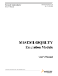
3.4.1 Hardware Connection
Use the cables that came with the MMEVS0508 for the hardware connection (the
Figure 3.2 depicts this connection). Configure the host to be a data terminal, so that it
sends data on the TxD lead and receives data on the RxD lead (as the MMEVS0508
hardware manual explains).
MMEVS0508 Target Interface
For More Information On This Product,
Go to: www.freescale.com
3–17
Freescale Semiconductor, Inc.
MM E V S T ar g e t I n t e r f ac e
3.5 Loading the MMEVS0508 Target
Freescale Semiconductor, Inc...
Figure 3.2
Hardware Connection
3.5 Loading the MMEVS0508 Target
Usually, the PROJECT.INI file specifies the target. To make the MMEVS the target,
change the file’s “Target=” line to “Target=Motosil”. The MotoSIL driver
automatically detects the MMEVS connection to your system. However, if the driver
detects nothing, an error message informs you that the target is not connected to the
expected port. Additionally, the Communications Device Specification dialog box
appears, so that you can set the correct baud-rate and communication-port parameter
values. See the Communication Configuration section of this document for more
details.
Another way to load the MMEVS0508 target is selecting Set Target... from the
Component Menu (See Figure 3.3), then choosing MotoSIL from the list of possible
targets.
Figure 3.3
Set Target menu
The MotoSIL driver automatically tries to find the MMEVS target, behaving as text
above explains.
3–18
MMEVS0508 Target Interface
For More Information On This Product,
Go to: www.freescale.com
Freescale Semiconductor, Inc.
M M E VS Ta rg et Int er f a ce
3.6 Communication Configuration
If MotoSIL does not detect a target, the MotoSIL menu remains in the main menu bar,
as shown in Figure 3.4:
Freescale Semiconductor, Inc...
Figure 3.4
Motosil Entry in menu bar
But after successful target loading, the MMEVS0508 menu replaces the Target or
MotoSIL menu in the main menu bar, as the Figure 3.5 depicts it.
Figure 3.5
MMEVS0508 in menu bar
3.6 Communication Configuration
In most situations, Debugger uses its default values to set communication with the
MMEVS automatically. In case of any problem, the dialog box below appears, so that
you can correct settings.
Another way to open this dialog box is selecting
MotoSIL | Connect... from the menu bar (see Figure 3.6). This
method is appropriate if when previous connection attempts failed
and Motosil still is in the main menu.
NOTE
MMEVS0508 Target Interface
For More Information On This Product,
Go to: www.freescale.com
3–19
Freescale Semiconductor, Inc.
MM E V S T ar g e t I n t e r f ac e
3.6 Communication Configuration
Freescale Semiconductor, Inc...
Figure 3.6
To change the connection settings
Make sure that host-computer parameter values are correct; make sure that the serialcommunication setting is correct. Otherwise, communication between Debugger and
the target is not possible.
3.6.1 Communication Device Specification
If the host and target are not connected, or if the communication device is not properly
indicated, the Communications Device Specification (Figure 3.7) dialog box appears:
Figure 3.7
Communication Device Specification dialog
Type the name of an available communication device in the Communication Device
edit box, use the drop-down control to set the baud rate, then click Connect. (The
default communication device is COM1.)
Once connection succeeds, Debugger saves the settings as defaults for later debug
sessions. Should the connection fail, a message box so informs you, so that you can
define a new communication device. To quit the dialog box and the environment, click
Cancel.
3–20
MMEVS0508 Target Interface
For More Information On This Product,
Go to: www.freescale.com
Freescale Semiconductor, Inc.
M M E VS Ta rg et Int er f a ce
3.7 Debugger Status Bar for the MMEVS
NOTE
Saving the communication device and the baud rate through this
dialog box overrides environment variables BAUDRATE and
COMDEV of the default.env file
Freescale Semiconductor, Inc...
3.6.2 Data Format
The MMEVS0508 data format is 8 data bits, 1 stop bit, no parity, and a variable baud
rate. The default speed is 9600 baud, unless you change this default via the menu
selection MMEVS0508 | Communication....
Communication speeds of 1200 through 115200 baud are available, depending on the
host-computer hardware.
3.7 Debugger Status Bar for the MMEVS
Once you have loaded the MMEVS target component, the Debugger status bar gives
specific information, as explained by Figure 3.8.
Figure 3.8
Status Bar
From left to right, this information is: the serial-communication baud rate, the
Debugger running mode, the MCU name (depending on the MCU-Id), and the
debugger status.
3.8 MMEVS0508 Menu Entries
MMEVS0508 Target Interface
For More Information On This Product,
Go to: www.freescale.com
3–21
Freescale Semiconductor, Inc.
Freescale Semiconductor, Inc...
MM E V S T ar g e t I n t e r f ac e
3.8 MMEVS0508 Menu Entries
3.8.1 Communication Baud Rate
You should specify the baud rate for host-computer-to-MMEVS0508 communication
early in a session. The system operates most efficiently at the maximum baud rate that
the host computer supports.
You can modify this baud rate, as text below explains.
3.8.2 Communication
Select MMEVS0508 | Communication... to display the Communication Device
Specification dialog box, as shown in Figure 3.9. Use the drop-down control to specify
the maximum value (115200 baud), or to specify the maximum rate your host
supports. If communication fails, Debugger reverts to the previous successful baud
rate.
Figure 3.9
3–22
Communication device specification
MMEVS0508 Target Interface
For More Information On This Product,
Go to: www.freescale.com
Freescale Semiconductor, Inc.
M M E VS Ta rg et Int er f a ce
3.8 MMEVS0508 Menu Entries
3.8.3 Maximum Baud Rate
The maximum baud rate depends on the speed and interrupt load of the host computer.
For slow notebook computers, or for computers running in a network, the maximum
baud rate may be as low as 19200. A buffered I/O card may allow the maximum rate
of 115200 for any host computer. The default value is 9600.
Freescale Semiconductor, Inc...
3.8.4 Show Protocol
If you check the Show Protocol check box, the system reports all commands and
responses in the command line window.
NOTE
Motorola or Metrowerks support personnel use this feature.
3.8.5 Memory Configuration
To view the memory layout, choose MMEVS0508 | Memory Map.... This opens the
Memory Configuration dialog box, illustrated by Figure 3.10
Figure 3.10
Memory Configuration
This dialog box shows the target’s memory setup. The system automatically loads this
setup if you check the Auto select according to MCU-Id check box. Debugger
MMEVS0508 Target Interface
For More Information On This Product,
Go to: www.freescale.com
3–23
Freescale Semiconductor, Inc.
MM E V S T ar g e t I n t e r f ac e
3.8 MMEVS0508 Menu Entries
identifies and sets the memory map through the processor MCU-Id. To open another
configuration, click the Open button. To save modifications to the current
configuration, click the Save... button.
3.8.6 Personality (.MEM) Files
For proper operation, the Motosil target must load the personality file (.MEM file) that
matches the connected Emulation Module (EM).
Freescale Semiconductor, Inc...
The.MEM file filename format is:
0nnnnVxx.MEM
where ‘nnnn’ is the four-digit, hexadecimal ‘MCU-Id’ number of the MCU, and ‘xx’
is a two-digit version number.
If that target cannot find this file, or if the file is not valid, the Error message box
shown in Figure 3.11 appears.
Figure 3.11
Personality file not found
Click Cancel to open the Communication Device Specification dialog box, instead of
establishing the connection.
Click Retry to bring up the Open Personality File dialog box, represented in Figure
3.12
3–24
MMEVS0508 Target Interface
For More Information On This Product,
Go to: www.freescale.com
Freescale Semiconductor, Inc.
M M E VS Ta rg et Int er f a ce
3.8 MMEVS0508 Menu Entries
Freescale Semiconductor, Inc...
Figure 3.12
Open personality file
This dialog box lets you browse to find and open the necessary.MEM file.
If you select another invalid.MEM file, the error message box and the Communication
Device Specification dialog box reappear.
If the .MEM file is valid, the target loads the file, copying it into the \PROG\MEM
directory, with ‘V00’ as the version number (for example, 00A18V00.MEM).
Note that the Memory Configuration dialog box displays the current memory map.
When starting Debugger:
If you have checked the Auto Select according MCU-ID checkbox, the system
automatically loads the default personality file for the MCU-ID. If this checkbox is
clear, the system automatically loads the most recently opened or saved memory map
file.
You can use the Memory Configuration dialog box to modify the memory
configuration, then save this new configuration into a memory configuration file.
(Click the Save button.)
You can use the Memory Configuration dialog box to load a different memory
configuration file (one that you previously defined and saved). (Click the Open
button.)
Another way to load personality files (or any memory configuration files) is to enter
the LOADMAP command in the command line.
MMEVS0508 Target Interface
For More Information On This Product,
Go to: www.freescale.com
3–25
Freescale Semiconductor, Inc.
MM E V S T ar g e t I n t e r f ac e
3.8 MMEVS0508 Menu Entries
3.8.7 Memory
Freescale Semiconductor, Inc...
The Memory area lets you specify the “Real-Time Memory”. For the MMEVS0508,
this is dual-ported memory that you can assigned to any valid RAM or ROM address.
While the MMEVS0508 is running, Debugger can display and modify this “RealTime Memory”. However, if a portion of this memory overlays internal MCU I/O,
RAM, or EEPROM, the Memory Configuration dialog box can only display, not
monitor, that memory portion.
3.8.8 Signals Emulation
To specify MMEVS0508 emulator signals, choose the MMEVS0508 | Emul Signals...
menu selection. This opens the Target Signals dialog box, depicted in Figure 3.13.
Figure 3.13
Target Signal dialog
This dialog box lets you specify the MCU clock and the reset signal connection.
Warning: in order to use any of these clock signals, you must configure EM jumper
headers correctly.
3.8.9 MCU Clock
The MCU Clock area lets you specify a different MCU clock, provided that the EM
configuration is correct.
3.8.10 Reset
The Reset area lets you specify the reset-signal connection with the target system.
3–26
MMEVS0508 Target Interface
For More Information On This Product,
Go to: www.freescale.com
Freescale Semiconductor, Inc.
M M E VS Ta rg et Int er f a ce
3.9 Default Target Setup
The Target Signals dialog box displays settings that the system reads from the
MMEVS0508. Click Ok to close the dialog box, and to write values back to the
MMEVS0508. Check the Save and Reload checkbox to have the system save the
configuration, then reload this configuration the next time you start the Debugger
debugger.
Freescale Semiconductor, Inc...
3.9 Default Target Setup
As with any target, you can use the Target menu to load the MMEVS target
component, or you can set the MMEVS target component as a default in the
PROJECT.INI file. This file should be in the project directory.
Example of PROJECT.INI file:
[DEFAULTS]
Window0=Source
0
0
50
40
Window1=Assembly
50
0
50
40
Window2=Register
50
40
50
30
Window3=Memory
50
70
50
30
Window4=Data
0
40
50
25
Window5=Command
0
65
50
20
Window6=Module
0
85
50
15
Target=Motosil
[Motorola ESL]
COMDEV=COM2
BAUDRATE=57600
SHOWPROT=1
NOTE
For more information about the PROJECT.INI file, please see the
Debugger manual.
MMEVS0508 Target Interface
For More Information On This Product,
Go to: www.freescale.com
3–27
Freescale Semiconductor, Inc.
MM E V S T ar g e t I n t e r f ac e
3.10 Motorola ESL Parameters
3.10 Motorola ESL Parameters
In normal use, you set these parameters in the PROJECT.INI file once, interactively,
during installation. You use these parameter values in subsequent debugging sessions.
3.10.1 COMDEV
Freescale Semiconductor, Inc...
This parameter specifies the host-computer communication port. COM1 is the default
communication device for PCs. The default for UNIX systems is /dev/ttya.
For a PC: Any valid communication device (COM1,COM2,etc.).
Example:COMDEV=COM2
For SUN:Any valid communication device (/dev/ttya, etc.).
Example:comdev=/dev/ttyb
3.10.2 BAUDRATE
This parameter specifies the communication baud rate between the host computer and
the target system. The Debugger default is 9600 baud, but you may set any of these
baud rates:
1200, 2400, 4800, 9600, 19200, 28800,
38400, 57600, 115200.
Example:BAUDRAUTE=19200
3.10.3 SHOWPROT
This parameter specifies whether to report commands and responses in the command
line window. To have the system report the commands and responses, give this
parameter the value 1. To have the system not do this reporting, give this parameter
the value 0. (Another way to specify reporting is checking the Show Protocol
checkbox of the Communication Device Specification dialog box.)
Please see the section Communication Configuration, Communication Device
Specification.
3–28
MMEVS0508 Target Interface
For More Information On This Product,
Go to: www.freescale.com
Freescale Semiconductor, Inc.
A
Freescale Semiconductor, Inc...
Appendix
A.1 MMEVS Commands
This section explains the commands specific to the MMEVS.
Use these commands as you would any others, typing them in the Command Line
component or when inserting them into a command file.
For further details about commands, please see the Debugger manual appendix,
Debugger Commands, as well as the section Command Line Component.
A.1.1 Baud Rate Command
BAUD
A.1.1.1 Short Description
sets the communication baud rate
A.1.1.2 Syntax
BAUD [rate]
rate: specifies the new baud rate; must be one of these decimal integer constants:
1200, 2400, 4800, 9600, 19200, 28800, 38400, 57600, 115200.
A.1.1.3 Description
The BAUD command sets or displays the baud rate for communication between the
system controller and the host computer. For maximum performance, the baud rate
should be as high as the host computer can accommodate. The maximum rate is
115200; the default baud rate is 9600.
MMEVS0508 Target Interface
For More Information On This Product,
Go to: www.freescale.com
A–1
Freescale Semiconductor, Inc.
App en d ix
A.1 MMEVS Commands
Without a rate value, the command displays the Communications Baud Rate
Specification dialog box for interactive rate selection. If the system does not support
the requested rate, the red message, “Error: <baud rate> is not a supported baud
rate.”appears in the Command Line window.
Example:
BAUD 57600
Freescale Semiconductor, Inc...
Changes the communication baud rate to 57600.
A.1.2 Target Signal Emulation Command
SIG
A.1.2.1 Short Description
sets emulator signals
A.1.2.2 Syntax
SIG [ [ENABLE] signal {signal}] [ DISABLE signal {signal}]
signal: The signal to be enabled or disabled: RESETIN or RESETOUT.
ENABLE: Connect the signal from the target system.
DISABLE: Disconnect the signal from the target system.
A.1.2.3 Description
The SIG command enables or disables reset control signals from the target MCU. If
the command specifies any signals, but lacks either keyword ENABLE or DISABLE,
the command enables the signals.
Examples:
SIG ENABLE RESETIN
Enables the “reset in” signal from the target system.
A–2
MMEVS0508 Target Interface
For More Information On This Product,
Go to: www.freescale.com
Freescale Semiconductor, Inc.
App en d ix
A.2 Other Commands
A.1.3 Reset Command
RESET
Freescale Semiconductor, Inc...
A.1.3.1 Short Description
resets target MCU
A.1.3.2 Syntax
RESET [GO|STOP]
GO: Resets the MCU and does a Go from Reset.
STOP: Resets the MCU and stops (default).
A.1.3.3 Description
The RESET command resets the target MCU.
Examples:
Reset Go
Resets the MCU and does a GO from Reset.
Reset
Resets the MCU and stops (default setting).
After the system asserts the reset is asserted, it executes the RESET.CMD command
file.
A.2 Other Commands
LOADMAP
A.2.0.1 Short Description
loads memory map
MMEVS0508 Target Interface
For More Information On This Product,
Go to: www.freescale.com
A–3
Freescale Semiconductor, Inc.
App en d ix
A.2 Other Commands
A.2.0.2 Syntax
LOADMAP fileName | MCUID
fileName: the full pathname of a file that defines a memory map.
MCUID: the MCU identifier. If the command includes an MCUID value, the system
loads a memory map from the file that matches this value.
Freescale Semiconductor, Inc...
A.2.0.3 Description
The LOADMAP command loads a memory map from a file. The file specification
must be the full pathname. If the file is in the current directory, the characters “.\”
must preceded the name (for example: LOADMAP .\00123V22.MEM).
Example:
LOADMAP 0xC17
Loads a memory map from a file that matches this MCU identifier (for the
68HC08AX48 MCU).
Note that the MCUID identifies an MCU, not an EM Board. The memory map
filename has this format:
0nnnnVvv.MEM
where ‘nnnn’ is the four-digit, hexadecimal ‘MCU-ID’, and ‘vv’ is a two-digit version
number.
MEM
A.2.0.4 Short Description
displays the memory map
A.2.0.5 Syntax
MEM
A.2.0.6 Description
The MEM command displays the current memory map.
Example:
A–4
MMEVS0508 Target Interface
For More Information On This Product,
Go to: www.freescale.com
Freescale Semiconductor, Inc.
Freescale Semiconductor, Inc...
App en d ix
A.2 Other Commands
in>MEM
Type
Addresses
Comment
------------------------------------------------------IO
0.. 3F PRU or TOP
TOP board resource or the PRU
NONE
40.. 4F NONE
RAM
50.. 64F RAM
NONE
650.. 7FF NONE
EEPROM
800.. A7F EEPROM
NONE
A80..3DFF NONE
ROM
3E00..FDFF ROM
IO
FE00..FE1F PRU or TOP
TOP board resource or the PRU
NONE
FE20..FFDB NONE
ROM
FFDC..FFFE ROM
COP
FFFF..FFFF special ram for cop
RT MEM
0.. 3FF (disabled)
-------------------------------------------------------
OSC
A.2.0.7 Short Description
selects emulator clock frequency
A.2.0.8 Syntax
OSC [rate | source]
A.2.0.9 Description
The OSC command selects the emulator clock frequency: one of five internally
generated frequencies (16 Mhz, 8 Mhz, 4 Mhz, 2 Mhz, or 1 Mhz) or an external clock
source. The firmware sets the default emulator clock rate, adapting it to the current
frequency.
Entering this command without parameters opens the corresponding dialog box.
OSC [rate | source]
where rate is:
OSC1MHZ
Selects the 1 Mhz oscillator.
MMEVS0508 Target Interface
For More Information On This Product,
Go to: www.freescale.com
A–5
Freescale Semiconductor, Inc.
App en d ix
A.2 Other Commands
OSC2MHZ
Selects the 2 Mhz oscillator.
OSC4MHZ
Selects the 4 Mhz oscillator.
OSC8MHZ
Selects the 8 Mhz oscillator.
OSC16MHZ
Selects the 16 Mhz oscillator.
Where source is: EXT
Selects an external clock source.
Example:
Freescale Semiconductor, Inc...
OSC OSC8MHZ
// Use the 8 Mhz internal emulator clock.
PROTOCOL
A.2.0.10 Short Description
controls Show Protocol functionality
A.2.0.11 Syntax
PROTOCOL [ON | OFF]
ON: Reports commands and responses in the command line window (default value for
this command).
OFF: Does not report commands or responses in the command line window; does not
log commands or responses in the log file.
A.2.0.12 Description
The PROTOCOL command controls reporting commands and responses in the
command line window. Entering this command without a parameter value has the
same effect as entering the command with the parameter value ON.
A–6
MMEVS0508 Target Interface
For More Information On This Product,
Go to: www.freescale.com
Freescale Semiconductor, Inc.
Index
Symbols
Removing the EM 11
Reset Switch 12
Signal Descriptions, Connector 13
.MEM 24
B
I
Freescale Semiconductor, Inc...
BAUD 1
BAUDRATE 21, 27, 28
Introduction 5
J
C
Cables, Connecting
Host Computer 11
Power 11
Target 11
COMDEV 21, 27, 28
Commands 1
Communication Baud Rate 22
Communication Configuration 17
Configuration 16
Memory 23
Connector, Cable
Pin Assignments 12
Signal Descriptions 12
D
Data Format 21
default.env 21
DLL 16
Dynamic Linking 17
E
EM
Installing 10
Removing 11
Emulation 26
Jumper Headers
Factory Test (J1) 9
Port Voltage Control (J2–J4) 9
L
LOADMAP 25
M
MCU Clock 26
MCU clock 26
MCU-Id 23
MEM 4
Memory 26
Memory Configuration 23
Menu 21
MMEVS05
Introduction 5
MMEVS0508 16
MMEVS0508 Server 17
MMEVS08
Introduction 5
MotoSIL 18
Motosil 27
O
OSC 5
H
Hardware Connection 17
Hardware Installation
Configuring the Platform Board 8
Connecting Cables 11
Installing the EM 10
Introduction 7
Pin Assignments, Connector 13
P
Parameters 27
Personality file 24
Pin Assignments, Connector 13
Platform Board, Configuration 8
Port Voltage Control Jumper Headers (J2–J4) 9
PROJECT.INI 18, 27
MMEVS0508 Target Interface
For More Information On This Product,
Go to: www.freescale.com
IDX–1
Freescale Semiconductor, Inc.
PROTOCOL 6
R
RESET 3
Reset 26
Reset signal connection 26
Freescale Semiconductor, Inc...
S
SHOWPROT 28
SIG 2
Signals 26
System
Components 6
Connections
11
T
Target 18
Target Setup 27
IDX–2
MMEVS0508 Target Interface
For More Information On This Product,
Go to: www.freescale.com