1
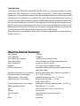
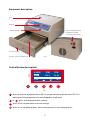
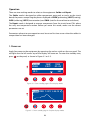
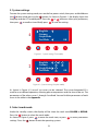
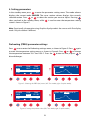
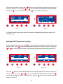
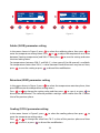
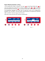
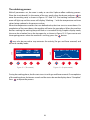
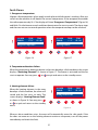
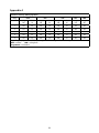
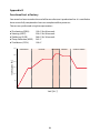
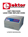
electronics worldwide
smt precision
lead-free reflow oven
USER MANUAL
Associated publications
Elektor SMT Precision Reflow Oven, Elektor October 2008.
Before Baking…, Elektor October 2008.
Baking…, Elektor October 2008.
© Elektor International Media 2008
www.elektor.com
www.elektor.de
www.elektor.es
www.elektor.nl
www.elektor.fr
Disclaimer
Elektor International Media b.v. shall not be liable in contact, tort, or otherwise, for any loss or damage suffered by
the purchaser(s) whatsoever or whosoever arising out of, or in connection with, the use of this equipment, other
than, at the option of Elektor International Media, to refund the purchaser money in respect of the equipment if
purchaser(s) returns equipment in unused, resalable condition, after having obtained written approval to do so from
Elektor International Media b.v.
Any use of the oven not explicitly described in this manual is strongly advised against and will void purchaser’s
warranty.
Equipment not suitable for heating foodstuffs, liquids or tissue.
Equipment must not be used in the vicinity of children, animals or unqualified people.
Contents
Introduction . . . . . . . . . . . . . . . . . . . . . . . . . . . . . . . . . . . . . . . . . . . . 4
Main technical features . . . . . . . . . . . . . . . . . . . . . . . . . . . . . . . . . . . . . 4
Equipment description . . . . . . . . . . . . . . . . . . . . . . . . . . . . . . . . . . . . . 5
Control button descriptions . . . . . . . . . . . . . . . . . . . . . . . . . . . . . . . . . . 5
Function of the temperature curve . . . . . . . . . . . . . . . . . . . . . . . . . . . . . 6
Common alloy solder temperature curve adjustment parameters . . . . . . . . . 8
Common alloy solder physical constant and characteristics . . . . . . . . . . . . . 9
Operation . . . . . . . . . . . . . . . . . . . . . . . . . . . . . . . . . . . . . . . . . . . . . 10
The soldering process . . . . . . . . . . . . . . . . . . . . . . . . . . . . . . . . . . . . . 16
Fault alarms . . . . . . . . . . . . . . . . . . . . . . . . . . . . . . . . . . . . . . . . . . . . 17
Cautionary Notices . . . . . . . . . . . . . . . . . . . . . . . . . . . . . . . . . . . . . . . 18
Appendix A: parameters of factory-defined programmes . . . . . . . . . . . . . . 19
Appendix B: functional test at factory . . . . . . . . . . . . . . . . . . . . . . . . . . 20
Appendix C: tray temperature vs. displayed temperature . . . . . . . . . . . . . . 21
Appendix D: Ball Grid Array (BGA) soldering . . . . . . . . . . . . . . . . . . . . . . 22
Warranty statement . . . . . . . . . . . . . . . . . . . . . . . . . . . . . . . . . . . . . . 23
Introduction
The Elektor SMT PRECISION LEADFREE REFLOW OVEN is an electrical appliance used for
production and maintenance of circuit boards using SMT (surface mount technology)
components. The equipment employs far-infrared heating elements as well as high quality
temperature sensing devices and materials. By means of accurate control exercised by an
internal microcontroller, temperature curves are obtained that closely match the requirements
of circuit board production using SMT. The temperature control curve of the equipment can
be adjusted accurately, allowing optimum use of a wide range of solder paste products with
different material parameters. The oven can shut down and supply fault alarms automatically.
Its functions cover PCB soldering and reworking as well as SMD drying.
The performance and operation of the oven have been upgraded and improved from a
previous version.
Main technical features
Line voltage:
Line frequency:
Max. power consumption:
Heating methods:
Menu languages:
Readout:
Modes of operation:
230 VAC
50-60 Hz
1650 W (10 A fused internally)
infrared radiation and hot air mixed heating
English or German (partly)
LCD, Text mode or Graphics mode
automatic reflow soldering; repair (maintenance);
temp. adjustable
Temperature phases (curve sections): Preheat, heat, solder, heat retention, cool down.
Preheating temp. / time range:
70 ºC-150 ºC / 0-5 min.
Heating temp. / time range:
[preheating temp.] to 220 ºC / 0-5 min.
Soldering temp. / time range:
[heating temp.] to 280 ºC / 0-30 s
(0-60 s below 260 ºC)
Heat retention temp. / time range:
[soldering temp.] to [soldering temp. – 0 to 50 ºC)
Effective soldering area:
280×280 mm (11×11 inch)
Size:
418×372×250 mm (16.5×14.6×10 inch)
Weight:
16.7 kg (net)
Case and finish: steel, high-gloss gray lacquer finish
CE
compliant
RoHS
compliant
Equipment description
Case
Display
Control buttons
Power receptacle, fuse
and power on/off
switch (on rear panel)
Drawer handle
Drawer with SMT board tray
Figure 1.
Control button descriptions
SOLDER
PREH
TEMP
150 ºC
EXIT
TIME
02 : 00
SET
Figure 2.
: press to turn the equipment on or off. It is not possible to switch the oven OFF if it is
working or if the temperature has not dropped to a safe level.
or
: press to change parameter settings.
: press to run set parameters and save settings.
: press to run complete process, exit running process or exit setting process.
Function of the temperature curve
In the SMT production process the temperature curve should be adjusted according to
different alloys of solder tin used, as well as the solder paste used, aiming to achieve the
best quality of the finished product. Usually, reflow soldering comprises five temperature
phases (curve segments). The temperature and the time of each phase can be set to satisfy
the combined requirements of different circuit boards. The various temperatures and
their role for the reflow phases are described individually.
1.
Preheating phase
Heating the PCB from room temperature to 120-150 ℃ serves to evaporate moisture, as
well as to eliminate internal stresses and residual gasses of the PCB. By setting a period
of 1 to 5 minutes for this segment, preheating is also a gradual transition to the next
temperature phase, the optimum time depending on board size and the number of the
components.
2.
Heating phase
Heating activates the liquid flux contained in tin alloy, enabling it to remove oxide layers
from SMDs in preparation for soldering. For low-temperature lead alloy solder and
precious metal alloy solder tin, the temperature in this phase should be set between 150 ºC
and 180 ºC, for example, the Sn42%-Bi58% and Sn43%-Pb43%-Bi14% alloys. For midtemperature lead solder alloys, set the temperature between 180 ºC and 220 ºC. For high
temperature lead-free solder alloys the temperature should be set between 220 ºC and
250 ºC. If you have reliable technical information on the solder material(s), the temperature
of the heating phase can be set to about 10 ºC below the tin/solder melting point for best
results.
3.
Soldering phase
This phase serves to finish the SMT soldering process. It has the highest temperature in the
soldering process, hence components are easily damaged if the temperature and/or time
are set incorrectly. The process is marked by substantial physical and chemical changes to
the solder, which determine to a large extent the success of the entire soldering process.
If you have reliable technical information on the solder material(s) in solid and liquid state,
the soldering temperature can be set 30-50 °C above the melting point.
Solder material may be divided into three groups:
- low temperature (150-180 ºC);
- mid-temperature (190-220 ºC);
- high-temperature (230-260 ºC).
Currently, lead-free solder materials for high-temperature soldering are the widest used.
Low-temperature lead-free variants based on precious metals are also available for special
requirements. At present, many lead-free solder materials are no substitute for lead
solder as mid-temperature leaded solder has excellent properties in terms of electrical
conductance, mechanical behaviour, hot and cold impact resistance, and the ability to act
as an anti-oxidant.
In this segment you can set the time according to several requirements discussed below.
After high-temperature melting of the solder, all SMDs effectively float on the surface of
the liquid solder. As a result of surface tension exerted by the flux and liquid, components
will be pulled to the centre of solder pads, causing parts to be repositioned automatically.
The solder flux vapour, solder tin and the metal surface of components together form an
alloy layer that, by infiltration, yields structures ideal for soldering.
A large PCB surface area and large component pads on the PCB generally govern a relatively
long soldering time (10-30 s). However, this stage should be kept as short as possible to
protect the components from damage due to overheating.
4.
Heat retention phase
This phase enables high-temperature liquid solder to solidify into firm joints. Solidification
quality has a direct impact the crystal structure of the solder and mechanical properties. If
the solidification process is too fast, rough crystalline will be formed causing a dull solder
joint of reduced mechanical strength. Under high temperature and mechanical impact,
such solder joints easily crack, eventually causing mechanical and/or electrical breakup
and reduced product durability. At slowly declining temperatures, solder can solidify and
crystallise properly. Generally set the temperature 10-20 ºC below the solder point. When
the temperature has dropped to the set value, natural cooling takes over.
5. Cooling phase
During this section of the temperature curve the temperature is reduced to a value that
allows PCBs to be removed from the oven without the risk of scalding your hands. To speed
up the cooling, you may also stop the process when the temperature drops below 150 ºC.
To avoid burns, use tools (pliers, tweezers) or heat resistant gloves
to take out the PCB board.
6. Note
In general, start from low-temperature curves, aiming to satisfy the soldering requirements
as much as possible to reduce the actual soldering temperature. Also note that longer heat
retention times allow shorter soldering times to be used — this will help to protect lowtemperature components, especially some types of connector and plug, from melting or
deforming. Components that do not fit the soldering temperature requirement should be
handled separately after reflow soldering.
Common alloy solder temperature curve adjustment parameters
Preheat
Heating
Soldering
ºC /30s
Retain
(‘Keep’)
ºC
ºC /min
ºC /min
Cool
Sn43-Pb43-Bi14
100-120
130-150
200-210
170
150
Lead-free,
low temperature
Sn42-Bi58
100-120
120-130
180-200
150
150
Lead-free,
low temperature
Sn48-In52
100-120
120-130
180-200
150
150
Lead,
mid- temperature
Sn63-Pb37
130-150
170-180
230-240
180
150
Lead,
mid- temperature
Sn60-Pb40
130-150
170-180
230-240
180
150
Lead,
mid- temperature
Sn62-Pb46-Ag2
130-150
170-180
230-240
180
150
Lead-free,
mid-temperature
Sn96.5-Ag3.5
130-150
180-190
240-250
240
150
Lead-free,
mid-temperature
Sn87-Ag3-Cu3-In7
130-150
180-190
240-250
240
150
Lead-free,
mid-temperature
Sn91-Zn9
130-150
180-190
240-250
230
150
Lead-free,
mid-temperature
Sn95.4-Ag3.
1-Cn1.5
130-150
180-190
250-260
240
150
Lead-free,
mid-temperature
Sn99.3-Cu0.7
130-150
180-190
270-280
260
150
Lead-free,
high temperature
Sn94-Ag3-Cu3
130-150
190-220
240-250
240
150
Lead-free,
high temperature
Sn97-Cu3
130-150
190-220
270-280
250
150
Lead-free,
high temperature
Sn95-Sd5
130-150
190-220
270-280
250
150
Solder Type
Composition
Lead,
low-temperature
Melting
temperature
Solder Alloy
Mechanical properties
Conductivity
Common alloy solder physical constants and characteristics
Liquidus
(ºC)
Push
Strength
(MPa)
Elongation
(%)
Rigidity
(HB)
37
183
61
45
16.6
11.0
40
183
10
90
299
41
45
12.7
8.2
Sn
Pb
63
60
Ag
Sb
Bi
In
Au
Cu
Zn
5
95
312
30
46
12.0
7.8
62
36
2
179
64
39
16.5
11.3
1
97.5 2.5
309
31
50
9.5
7.2
3.5
221
45
55
13
13.4
97.5 2.5
304
30
52
9.0
8.8
245
40
38
13.3
11.9
14
163
55
57
14
8.0
58
138
77
20-30
19.3
5.0
117
11
83
5
11.7
13.0
96.5
95
43
5
43
42
48
52
15
5
80
20
96.5
87
3
7
157
17
58
5
80
280
28
-
118
75
3.5
221
20
73
40
14.0
221
45
60
14
9.0
3
91
95.4
9
3.1
99.3
95
199
1.5
217
0.7
227
5
240
Operation
There are two working modes to select on the equipment: Solder and Repair.
The Solder mode is designed to solder components onto pads or tracks on the circuit
board, the process comprising the phases displayed as PREH (preheating), HEAT (heating),
SLDR (soldering), KEEP (heat retention) and COOL (wait for the machine to cool down).
The Repair mode is designed to remove components from the circuit board. This phase
has only one temperature section. Before you enter this mode, make sure the correct
parameters are set.
Parameters relevant to oven operation must be set on first time use or when the solder tin
composition has been changed.
1. Power on
Apply line power to the equipment by operating the rocker switch on the rear panel. The
red light near the left corner top of the display will come on. To enter the standby state,
press
on the panel, as shown in Figure 3-1 or 3-2:
SOLDER
PREH
TEMP
150 ºC
RUN
TIME
02 : 00
SET
Figure 3-1. Oven standby page in Text-display mode.
SOLDER PREH T:150ºC S: 00 : 30
1
300
200
Figure 3-2. Oven standby page in Graphic-display mode.
10
2. System settings
To enter the system setting mode, turn on the line power switch, then press and hold down
the
button while pressing the
button. As shown in Figure 4-1, the display shows the
language and the LCD mode options. Press the
or
button to select your preference,
then press
to confirm it and finally press
to save the setting.
English √
German
GraphMode
TextMode √
OK
Figure 4-1. System setting (Text mode).
English √
German
GraphMode
TextMode
0
1
√
4
5
2
3
OK
Figure 4-2. System setting (Graphic mode).
As shown in Figure 4-2, one of six curves can be selected. The curve designated ‘0’ is
used for user-defined operation, allowing phase temperature and the time to be set. The
parameters of the other curves 1 through 5 are fixed. You can find the parameters of each
curve in the table in the Appendix.
3. Select work mode
Under the standby screen, the display will be show the work state SOLDER or REPAIR.
Press the
button to select the work mode.
As shown in Figure 3, press
to enter the work state, or press
to enter parameters
settings. Press the
button to exit the operating system.
11
4. Setting parameters
In the standby menu press
to enter the parameter setting menu. The mode column
displays the current mode SOLDER. The curve section column displays the currently
selected section. Press
or
to select the section you want to adjust. Pressing
takes you back to the standby menu, while
is used to enter the temperature setting
state as shown in Figure 5.
Note: Functionally, the operation using Graphics display mode is the same as with Text display
mode. Only the readout is different.
Preheating (PREH) parameter settings
Press
once to enter the Preheating settings menu, as shown in Figure 5. Press
again
to enter the temperature setting menu, as shown in Figure 6. Press
or
to change
the temperature between 70 ºC and 150 ºC. Press the
button to save, or press
to
discard changes.
SOLDER
PREH
TEMP
150 ºC
SOLDER PREH T:150ºC S: 00 : 30
TIME
02 : 00
300
200
EXIT
SET
Figure 5. Selecting the PREH(eat) menu (left: Text mode; right: Graphic mode).
SOLDER
PREH
TEMP
150 ºC
SOLDER PREH T:150ºC S: 00 : 30
TIME
02 : 00
300
200
EXIT
OK
Figure 6. Setting the preheat value (left: Text mode; right: Graphic mode).
12
1
After the temperature setting, press
once to enter the time parameter setting state, as
shown in Figure 7 (8). Press the
or
key to set the time between 0 and 5 minutes,
then press
to save the value. Next, press
to enter the standby state.
SOLDER
PREH
TEMP
150 ºC
SOLDER PREH T:150ºC S: 00 : 30
TIME
02 : 00
300
200
EXIT
OK
Figure 7.
Figure 8.
In Graphic display mode, the curve will be redrawn automatically after returning to the
standby state.
Heating (HEAT) parameter setting
As illustrated in Figure 9, press the
key to select the heating phase. When the screen
displays ‘HEAT’, press
to enter the temperature setting. As shown in Figure 10, you press
or
to set the temperature to a value between [preheating temperature] and 220 ºC.
SOLDER
HEAT
TEMP
200 ºC
EXIT
TIME
00 : 20
SOLDER
HEAT
OK
TEMP
200 ºC
EXIT
Figure 9.
TIME
00 : 20
OK
Figure 10.
Press the
button to save the temperature setting and proceed to the time setting. As
shown in Figure 11, press
or
to set a time between 0 and 5 minutes. Then press
to save the setting and return to Mode Select, or press
to enter the standby state, as
shown in Figure 12.
13
SOLDER
HEAT
TEMP
200 ºC
EXIT
TIME
01 : 00
SOLDER
PREH
OK
TEMP
150 ºC
RUN
Figure 11.
TIME
02 : 00
SET
Figure 12.
Solder (SLDR) parameter setting
In the menu shown in Figure 5, press
to select the soldering phase, then press
to
enter the temperature setting menu. Press
or
to adjust the temperature to a value
between [heating temperature] and 280 ºC. Next, press
to save the setting and enter
the time setting menu.
For temperatures between 250 ºC and 280 ºC, a time span of 0 to 30 seconds is available.
For temperatures lower than 250 ºC, a value between 0 and 60 seconds may be set. Next,
press
to save the setting or press
to discard the modification.
Retention (KEEP) parameter setting
In the menu shown in Figure 5, press
to select the temperature retention phase, then
press SET to enter the temperature setting menu.
Press
or
to change the setting value and then press
to save it, or press
to
discard the modification. The software prohibits setting a value smaller than 50 ºC below
that of the previous phase.
Cooling (COOL) parameter setting
In the menu shown in Figure 5, press
to select the cooling phase, then press
to
enter the temperature setting menu.
Press
or
to change the value from 70 ºC to that of the previous phase and then
press
to save it, or press
to discard the modification.
14
Repair Mode parameter setting
In the standby menu shown in Figure 13, first press
to select Repair Mode, then
to
enter the temperature setting menu as shown in Figure 14. Press
or
to adjust the
desired temperature, then press
to save. Repair Mode offers three temperature ranges.
For temperatures between 70 ºC and 150 ºC no time has to be set. For temperatures
between 150 ºC and 200 ºC, the time range is 0 to 60 minutes. For temperatures between
200 ºC and 250 ºC the time range is 0 to 5 minutes.
After the set time, the oven will shut down automatically.
REPAIR
HEAT
TEMP
200 ºC
EXIT
TIME
10 : 00
REPAIR
HEAT
OK
TEMP
200 ºC
EXIT
Figure 13.
OK
Figure 14.
15
TIME
10 : 00
The soldering process
With all parameters set, the oven is ready to start the 5-phase reflow soldering process.
Place the circuit board(s) in the centre of the tray, gently close the drawer and press
to
enter the working state, as shown in Figures 15-1 and 15-2. The ‘working’ indicator on the
oven will light up and the screen will display: “Working…” with the temperature and time
values being updated as the process evolves.
When the temperature reaches the user-defined value, the time starts to count down. On
completion of the count down, the machine will enter the next phase. When the machine
finishes working the working lamp will flash or is turned off. Using Graphics display mode,
the curve has a broken line as the time goes by, as shown in Figure 15-2. If you want to exit
the ongoing process when the machine is running, press the
button.
may also be pressed to stop extractor fan activity (for gas and fume removal) and
return to standby mode.
SOLDER
PREH
TEMP
107 ºC
SOLDER PREH T:150ºC S: 00 : 30
TIME
02 : 00
1
300
200
Working...
EXIT
Figure 15-1 (Text mode).
Figure 15-2 (Graphic mode).
During the cooling phase, the fan starts to assist with gas and fume removal. On completion
of the cooling phase, the buzzer sounds and the status bar on the display shows “Complete”.
Press
to repeat the process.
16
Fault Alarms
1. Dangerous temperature
Highest safe temperatures values apply to each phase while the oven is working. After you
switch on the machine it will detect the current temperature. If the temperature exceeds
the safe temperature by 10 ºC the display will show ‘Dangerous Temperature!’ (Figure 16)
and blink. First the buzzer sounds and then the extractor fan starts to work. The alarm stops
and the oven returns to normal operation when the temperature drops to the safe level.
SOLDER
ERROR:
TEMP
172 ºC
Dangerous Temperature!
TIME
02 : 00
SOLDER
ERROR:
EXIT
TEMP
--- ºC
Detecting Element!
Figure 16.
TIME
02 : 00
EXIT
Figure 17.
2. Temperature detection failure
When the temperature-detecting device in the oven develops a fault condition, the screen
displays “Detecting Element!” as shown in Figure 17. The buzzer is activated and the fan
starts to operate. You may press
or
to quit and return to the standby menu.
3. Heating element failure
When the heating element in the oven
develops a fault condition, the alarm will
sound and the fan starts to work. The
screen displays: ‘Heating Element Fault’
as shown in Figure 18. You may press
or
to quit and return to the standby
menu.
SOLDER
ERROR:
TEMP
35 ºC
Heating Element Fault
TIME
02 : 00
EXIT
Figure 18.
When an alarm condition arises, the oven will automatically enter the safe mode. If the
fan does not come on or the heating element continues to operate, turn off the power
immediately and check the fault.
17
Cautionary Notices
1. Do not connect other equipment on the same power outlet as used for the oven. Make
sure the outlet and the power cord maintain a proper protective earth (PE) connection
and are rated for at least 10 A (230 VAC version).
2. The Infrared Reflow Oven should be placed horizontally with at least 20 cms (8 inch)
clearance to other equipment, objects or walls.
3. Do not use the oven in wet or high temperature environments.
4. Do not use water to clean the oven case.
5. Do not insert anything in the metal grille on the fan, or block the air intake or outlet.
6. Do not place or use combustible or explosive materials in or near the machine. Do not
use the oven to dry materials or devices containing combustible gas(es).
7. To avoid damaging the internal infrared heat pipe, prevent objects from impacting the
oven case. If a heat pipe malfunction is detected, turn off the power supply and request
authorisation to return the unit for servicing.
8. Do not insert your hand(s) in the cabinet when the machine does not indicate that
the inside has reached a safe temperature. In case of doubt, wear safety goggles and
gloves.
9. To prevent blocking the air intake, do not use the machine when stood on a
tablecloth.
10. If the infrared heat pipe is damaged, the replacement part must be authorised by the
manufacturer to prevent damage and serious malfunctioning.
18
Appendix A
Parameters of factory-defined programmes
Prog.
KEEP
COOL
temp.
(ºC)
PREH
time
(s)
temp.
(ºC)
HEAT
time
(s)
temp.
(ºC)
SLDR
time
(s)
temp.
(ºC)
temp.
(ºC)
1
120
60
160
58
190
30
170
150
2
130
60
180
58
200
30
185
150
3
140
60
200
58
220
30
210
150
4
150
60
220
58
250
30
240
150
5
150
60
220
58
280
30
265
150
Note: Prog. = programme - PREH = preheating - HEAT = heating - SLDR = soldering KEEP = retention - COOL = cooling down.
Programme 0 = user-defined.
19
Appendix B
Functional test at factory
Your oven has been tested at the end of the manufacturer’s production line. It is certified to
have successfully completed at least two complete reflow processes.
The test was performed using these parameters:
✔ Pre-heating (PREH)
✔ Heating (HEAT)
✔ Soldering (SLDR)
✔ Temp. Retention (KEEP)
✔ Cool down (COOL)
300
PREHEATING
150 ºC for 60 seconds
220 ºC for 90 seconds
260 ºC for 30 seconds
245 ºC
150 ºC
HEATING
SOLDERING
KEEPING
COOLING DOWN
TEMPERATURE
[ºC]
250
200
150
100
50
0
0
30
60
90
120
150
TIME [SEC.]
20
180
210
240
270
300
Appendix C
Tray temperature vs. displayed temperature
The temperature value you may read on the display is the oven’s internal (air) temperature.
This can be slightly different from the temperature measured on the PCB tray. The latter
value is marginally lower in most cases.
For this reason it is strongly suggested to run a few dummy tests before starting volume
production of boards. The values given in Appendix A are good starting points allowing
you to tune the various times for best results.
21
Appendix D
Ball Grid Array (BGA) soldering
Although the equipment is suitable for soldering BGA devices, this should be done with
extreme caution, and only if sufficient expertise and experience has been developed by
the user(s).
The most difficult aspects of BGA soldering include
1. Component placement — this is extremely difficult by hand and really requires the use
of specialized (expensive) optical equipment with camera and even x-ray support;
2. Reflow curve pre-testing — a time-consuming series of experiments may be required
to arrive at a ‘known-good’ temperature curve for successful BGA soldering.
Users should be aware that the soldering BGA devices is a complex task and might fail if
he/she has little or no experience. It is recommended to
1. Refrain from using BGAs for any initial or beginners-level experiments with the oven.
2. Attend a hands-on seminar or workshop session on BGA soldering before trying the
process on your own.
The substance of the Disclaimer on the second page of this manual is reiterated here.
22
Warranty statement
Definitions
“The Company” shall refer to Elektor International Media B.V.
“The Package” shall refer to the hardware, software and other component parts of this product.
“The Period” shall be one year from the date of delivery.
Warranty
The Company warrants that this Package is free from significant defects in materials and workmanship for the Period.
This warranty is not transferable, and does not include software upgrades.
Checking your product
This Package has been tested in the factory in accordance with the Company’s quality guidelines. We strongly
recommend that you carry out your own tests with this product, in accordance with the User Test guidelines available
for the product, which will confirm for you that this Package meets the specification for which it has been designed.
Exclusions
This Package, or parts of it, should not be used in life-critical applications.
This warranty does not apply in the following cases:
• Where the Package has been damaged as a result of using it in ways other than for which it is intended. Intended
use is described strictly in the User Manual supplied with the Package
• Where the Package has been modified.
• As a result of service by a person not authorized by the Company.
• Where damage occurs through improper transportation or packaging.
• Where the Package is damaged through improper physical handling.
• Where parts of this Package are lost or damaged.
The Warranty does not apply to the consumable parts of this Package – e.g. ICs or components supplied with this
Package including IC(s) contained in programmable systems which can be damaged by erroneous use.
Disclaimer
Except for the limited warranties made in this document, the Company disclaims all other warranties – expressed,
implied or statutory – including, but not limited to, implied warranties of merchantability or fitness for a particular
purpose. In no event shall the Company be liable for any incidental, special, or consequential damages, including,
but not limited to, loss of business, profits, whether in action, contract or tort or based on a warranty, arising out of or
in connection with the use or performance of this Package. The only warranty offered is the repair or replacement of
the Package, or parts thereof at the Company’s discretion. The Company has the option to offer a refund, at its own
discretion, under all circumstances.
Obtaining warranty service
Subject to the provisions above, you are entitled to service with respect to the Package with the following terms
and conditions:
Claims will only be honoured if made within the Period.
• Before making a claim, please review the Package documentation – supplied electronically and/or on paper – and
contact relevant representatives of The Company.
• If you have problems, please contact the Company by telephone. Your assistance will be required in running any
diagnostic tests the Company may feel suitable to ascertain where the problem with the Package lies. This will
help in reducing the number of ‘no defect found’ problems.
• Where a diagnostic test by telephone identifies one component at fault, the Company may send – by post or
courier at the Company’s expense – a replacement part.
• Where a diagnostic fault determines that an upgrade of software is required then the Company reserves the right
to send this using email.
• Where it is not possible to determine the fault and repair it remotely, the Package, or parts of it, will need to be
returned to the Company. Please provide proof of purchase and serial numbers for any parts of the Package, as
well as proof of shipment.
• The company will seek to determine the fault with all returned Packages.
• Where a returned Package is found to be defective in materials or workmanship, the Company will replace or
repair the Package at its own expense.
• Where no fault is found with a returned Package, the Company reserves the right to make a reasonable charge to
compensate the Company for the time taken to service the Package.
23