1
Network Video Recorder
User’s manual
Ver. 1.0
Safety Precautions
You must observe the following rules when you use this product:
1.
Do not place any container (e.g. a cup) that holds liquid on the NVR.
2.
Please position the NVR in a well-ventilated room.
3.
Please use this device within the allowed temperature and humidity range.
4.
Dust on the PCB will lead to a short circuit once it is affected with damp. To ensure that the
device can run properly for a long term, please regularly remove dust from the PCB,
connector, chassis fan, chassis and other parts using a soft hair brush.
5.
How to connect the ground pole of the device: This system is designed with two ground
terminals: the system protection ground terminal and the heavy current discharge ground
terminal. Connect the protection ground wire (a copper wire, with a sectional area greater
than 0.75 square millimeter) led out from the system protection ground terminal to the
protection ground bar of the equipment room. The heavy current discharge ground terminal is
used to discharge heavy current led in by the line to the ground, thus ensuring that the device
runs normally. This port must be connected to the lightning protection ground end of the
system in accordance with the lightning protection standard and cannot be suspended.
Features
Audio and video input
Supporting connection to 8*D1/1*1080P+1*D1/1*720P+5*D1 digital camera.
Each video channel supports dual stream compression, and either code stream can be selected
for connection and implementing network browsing.
The video encoding parameters of each channel can be adjusted separately, such as the
resolution, frame rate, code rate and image quality.
Supporting video stream encoding and composite stream encoding of synchronous audio
stream and video stream
Supporting the watermarking technology
Supporting 8 channels video playback simultaneous
Local surveillance
Supporting three independent local outputs of VGA/HDMI, main audio/video port and
auxiliary audio/video port
VGA/HDMI high definition output, highest resolution can be up 1080P.
Supporting 1/4/8/9-image preview and adjustable preview channel sequence
Preview supports packet switching, manual switching or automatic polling preview. The
automatic polling cycle can be set.
Supporting video motion detection and video loss detection
Built-in mainstream PTZ decoder control protocol; supporting customized PTZ protocol
upgrade, as well as preset point, cruise path and track
Harddisk file management
Supporting up to 8 SATA harddisks; the capacity of each harddisk can be greater than 2TB.
Supporting the harddisk S.M.A.R.T technology
Supporting harddisk dormancy
Supporting harddisk pack management
Using the EXT3 file format, stable and reliable, and thoroughly eradicating generation of
harddisk fragments
Video recording and playback
Supporting the cyclic write-in mode and non- cyclic write-in mode
Supporting the manual, scheduled, alarm, motion detection and other video recording trigger
modes
Seven video recording time segments can be set in a day, and the video recording trigger
modes in different time segments can be set separately.
Supporting switching value alarm and pre-recording and delay video recording of motion
detection
Supporting search and playback of video recording by conditions such as channel number,
video recording type, file time and start/end time
Supporting pause, fast play, slow play, play forward, play backward and other functions
during playback
Data backup
Supporting backup through the USB interface
Supporting backup through the eSATA interface
Supporting mass backup
Supporting management and maintenance of backup devices
Alarm and exception management
Uniformly managing the switching value alarm input/output of the device and IP channel.
Uniformly managing the motion detection alarm and alarm on video signal unavailability of
the device and IP channel
Supporting arm time setting of alarm input/output
Supporting alarm on video signal unavailability, video motion detection alarm, harddisk error
alarm, and full harddisk alarm
All alarms and exceptions can trigger video recording of any channel, switching value alarm
output, buzzer alarm, and uploading to the alarm center.
The system can recover automatically when an exception occurs during its running.
Other local features
The user can operate the system through the front panel button, shuttle key, mouse, remote
control and dedicated keyboard.
Three-level permission user management; the administrator can create multiple operation
users and set permissions for them, and make permissions specific to channels.
Supporting recording and searching of complete operation, alarm, exception and information
logs
Supporting manual alarm triggering and clearing
Network features
Supporting the 10M/100M/1000M adaptive network interface
Supporting the TCP/IP protocol stack and protocols including PPPoE, DHCP, DNS, DDNS,
FTP and SMTP
Supporting unicast and multicast; supporting TCP, UDP and RTP in the case of unicast
Supporting remote search, playback and downloading of video recording files
Supporting remote access and configuration of parameters
Supporting remote access of the device running status, system log and alarm status
Supporting remote key pressing operation
Supporting remote harddisk formatting, program upgrading, restarting, powering-off and
other system maintenance operations
Supporting RS-232 and RS-485 transparent channel transmission
Uploading alarms and exceptions to the remote alarm host
Supporting remote manual triggering and stopping of video recording
Supporting remote manual triggering and stopping of alarm output
Supporting remote JPEG image capture
Supporting remote PTZ control
Supporting voice intercommunication or voice broadcasting
Designed with an embedded WEB Server
Development support
Providing a SDK software development kit
Providing application source codes for demonstration
Providing development support and development training service related to the application
system
Contents
CHAPTER 1 OPERATION INSTRUCTIONS ................................................................................................ 8
1.1 Front Panel Buttons and LEDs ............................................................................................9
1.2 Mouse ................................................................................................................................12
1.3 Remote Control .................................................................................................................13
1.4 Input Method .....................................................................................................................15
1.5 Menu .................................................................................................................................16
1.6 Power-on and Power-off ...................................................................................................17
CHAPTER 2 PREVIEW ................................................................................................................................ 19
2.1 Preview Interface Status ....................................................................................................20
2.2 Preview Operation.............................................................................................................21
2.3 Lock System ......................................................................................................................22
CHAPTER 3 VIDEO RECORDING.............................................................................................................. 23
3.1 Settings before Video Recording .......................................................................................24
3.2 Scheduled Video Recording ..............................................................................................25
3.3 Video Recording of Motion Detection ..............................................................................27
3.4 Shield Alarm .....................................................................................................................29
3.5 Sensor Alarm .....................................................................................................................30
3.6 Manual Video Recording ..................................................................................................32
CHAPTER 4 PLAYBACK ............................................................................................................................. 33
4.1 Channel Playback ..............................................................................................................34
4.2 Playback by Time ..............................................................................................................36
4.3 Playback by File ................................................................................................................38
CHAPTER 5 BACKUP ............................................................................................................................... 40
5.1 Backup Using USB Interface ............................................................................................41
CHAPTER 6 ALARM .................................................................................................................................... 43
6.1 Detector Alarm ..................................................................................................................44
6.2 Motion detection Alarm ....................................................................................................46
6.3 Detector alarm ...................................................................................................................48
6.4 Shield Alarm .....................................................................................................................50
6.5 Harddisk Alarm .................................................................................................................52
6.6 Alarm Info .........................................................................................................................54
6.7 Alarm Handling .................................................................................................................55
CHAPTER 7 DEVICE SETTING .................................................................................................................. 57
7.1 Search Add ........................................................................................................................58
7.2 Manual Add .......................................................................................................................60
7.3 Delete Device ....................................................................................................................62
7.4 Modify Device ..................................................................................................................63
7.5 OSD Configuration ...........................................................................................................65
7.6 Image Adjust .....................................................................................................................66
7.7.1 Motion Detection....................................................................................................67
7.7.2 Sensor Alarm ..........................................................................................................69
7.7.3 Shield Alarm...........................................................................................................70
CHAPTER 8 NETWORK .............................................................................................................................. 71
8.1 Network General Settings .................................................................................................72
8.2 Platform Parameters ..........................................................................................................73
8.3 FTP ....................................................................................................................................74
8.4 PPPOE...............................................................................................................................75
8.5 DDNS ................................................................................................................................76
CHAPTER 9 ................................................................................................................................................... 77
PTZ CONTROL ............................................................................................................................................. 77
9.1 PTZ Parameters Setting.....................................................................................................78
9.2 Set and invoke the preset position: ....................................................................................78
9.3 PTZ Control Operation .....................................................................................................80
CHAPTER 10 HARD DISK MANAGEMENT.............................................................................................. 82
10.1 Initializing Harddisk........................................................................................................83
10.2 Setting Hard Disk ............................................................................................................83
10.3 Formatting Hard Disk .....................................................................................................85
CHAPTER 11 DEVICE MAINTENANCE AND MANAGEMENT .............................................................. 87
11.1 User Management ...........................................................................................................88
11.2 Log Information ..............................................................................................................91
11.3 Version Upgrade ..............................................................................................................92
11.4 Time and Information Management ................................................................................93
CHAPTER 12 ................................................................................................................................................. 94
OTHER SETTINGS ....................................................................................................................................... 94
12.1 Setting System Language, Device Name and Other General Parameters .......................95
12.2 Video Parameters Setting ................................................................................................96
12.3 RS485 Keyboard Setting .................................................................................................97
12.4 Restore to Leave Factory Default Parameters .................................................................98
CHAPTER 13 APPENDIX ........................................................................................................................... 100
13.1 Glossary ........................................................................................................................101
13.2 FAQs .............................................................................................................................103
Chapter 1
Operation Instructions
1.1 Front Panel Buttons and LEDs
No.
Name
Description
1
Video recording
LED
Video recording LEDs of channels 1-16; blinking in green means
video recording status.
2
Harddisk LED
Normal operating LED of the harddisk; blinking in green means
normal operating status.
3
STATE LED
It is constantly on when the device is powered on; blinking in
orange means normal operating.
4
Network port
LED
Green means normal network operation; blinking means data
transmission.
5
PWR LED
6
Power button
This button is constantly on in blue when the device is electrified.
7
eSATA
The eSATA harddisk interface is used to connect to the eSATA
harddisk.
8
Mouse interface
The mouse interface is used to connect to the mouse.
9
USB
It is the USB interface.
10
Earphone
interface
It is the audio output interface of earphone.
11
Microphone
interface
It is the audio input interface of microphone.
The PWR LED is constantly on in red when the device is
electrified.
① Power ON/OFF
② AC 220Vnd
③ Discharge ground :when cascading multiple devices, must ground through the common
ground first , and then connect with the control keyboard and power input protection grou
④ LAN interface
⑤ RS-485 Serial Interface, KB keyboard interface( support concatenation)
⑥ Dial switch
⑦ RS-232 interface、VGA output
⑧ HDMI output
⑨ VOUT、AOUT
⑩ VOUT、AOUT
Noet: Grounding
1. Requirement of device grounding type
Type
Name
Function
Requirement
EGND
Discharge
ground
For discharge lightning surge and other
large electric current, to protect related
disturbed interfaces
Ensure a good connection with project
discharge ground, wire proportion >1.5
mm2, recommend multistrand wires
GND
System
ground
Potential reference ground of PCB
board and other parts (i.e. harddisk) of
device.
Ensure a good connection with system
discharge ground, wire proportion >1.5
mm2, recommend multistrand wires
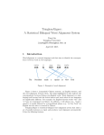
2. Ground
Condition
Method
Diagram
Discharge ground and
System ground
Discharge ground, system ground should be responding with
the project ground(EGND-EGND, GND-GND)and
connect,. NOT allowed to connect opposite or wrong
Picture 1
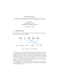
Two type grounds to
conbinning one
Short circuit the EGND, GND, then connect to the grounding
bar.
Picture 2
Picture 1 NVR discharge ground, system ground diagram
Picture 2 NVR system ground diagram
1.2 Mouse
Name
Action
Click
Selecting and confirming the operation item
Double-click
Switching to display single image and multiple images in the
preview and playback status
Press to drag
1. Setting the area scope in settings of motion detection and video
masking alarm area
2. Dragging the channel and time display scroll bars
3. Quickly access to PTZ control interface
Left key
Right key
Description
Click
Displaying the right-click menu
Note: If the mouse cannot be detected after it is connected, the possible reason is that the mouse is
incompatible with the NVR. Please replace the mouse.
1.3 Remote Control
No.
Key
Name
1
POWER
2
DEV
3
Numeric
Keys
Description
Powering off the device; press the POWER key
for more than 3 seconds to display the “Power
off” menu, and select “Power off” to turn off
the device.
Enabling/disabling the remote control; press
the [DEV] key, enter the device number of the
NVR to be operated (e.g., press the numeric
keys [0] and [1] if it is defaulted to “01”)
through the remote control, and then press the
[OK] key. Then, you can control the NVR
whose device No. is 01.
Entering numbers and capital and small
English letters, and switching 16 channels; You
need to press two numeric keys to switch 16
channels. For example, to switch to channel 1,
press the [0] key, and then press the [1] key in
1 S; to switch to channel 16, press the [1] key,
and then press the [6] key in 1 S.
Entering the editing status and deleting the
character before the cursor in the editing status
4
EDIT
5
A
6
REC
Entering manual video recording
7
PLAY
Entering search of video recording
8
INFO
Displaying the system information
9
VOIP
Entering the menu for setting main/auxiliary
interface screen split and polling
10
MENU
Entering the main menu of the system
11
PREV
12
Direction
Keys
Switching the entry status (numbers and capital
and small English letters)
Cyclically switching among 1 screen, 4
screens, 9 screens and 16 screens
Controlling the PTZ action in the PTZ control
status; in the play status, the [Up] key is used
for accelerating playing, the [Down] key is
used for slowing down playing, the [Left] key
is used for playing the previous file, and the
[Right] key is used for playing the next file; in
the preview status, the [Left] key is used to go
to the previous screen, and the [Right] key is
used to go to the next screen.
Controlling automatic PTZ revolving in the
PTZ control status and playing/pausing in the
play status
13
OK
14
PTZ
Entering the PTZ control menu
15
ESC
Exiting the menu
16
F1
Turning on/off the virtual keyboard in the
menu status
17
F2
Switching tabs in the menu status
18
FRAME
Playing forward or backward by I frame in the
video recording playback status
IRIS,
FOCUS
19
and ZOOM
Adjusting the iris, focusing and zooming
respectively
Keys for
lens control
20
LIGHT
Controlling switching of the PTZ light
21
WIPER
Controlling switching of the PTZ wiper
Precautions for using the remote control: Before using the remote control, make sure that the
batteries are installed correctly. In operation, point the infrared transmitting end of the remote
control to the infrared receiving port of the NVR. If operation fails, enter “Setup Menu” -->
“General”--> “Options” and check “Device ID” of this device; press the [DEV] key on the remote
control, enter the device ID of this NVR to be operated and the press the [OK] key on the remote
control. Now, if the NVR completely receives the remote control instructions, you can operate this
NVR by using the remote control. In the entire operation procedure, there is no prompt
information on the NVR panel or monitor. If the remote control cannot control the device, try it
again: press the [DEV] key, enter the device ID, and press the [OK] key. If control still fails after
many attempts, check as follows to find out the reason: 1. Check positive and negative polarities
of the batteries; 2. check if the batteries are exhausted; 3. check if the remote control sensor is
obstructed; 4. check if any fluorescent lamp is on nearby. If the remote control cannot function
well after the above reasons are eliminated, replace it; if the new remote control cannot function
either, contact the supplier.
1.4 Input Method
Icon
Description
Canceling the current input content in the Chinese character input status
…
Number input keys
Entering “.” and “@” in the English letter input status; “-” and “+” are
displayed in the Chinese character input status and used for turning pages of
candidate characters.
or
New line key
…
Letter input keys
Backspace key for deleting
Caps Lock key
Enter key
Chinese character and English word switching key
Space key (it is used to confirm Chinese phonetic alphabets and display
candidate Chinese characters when Chinese phonetic alphabets are entered)
Mouse/keyboard input(Display current input is Allah Number, uppercase
English or not of the mouse or keyboard)
Editor Number
Icon
Description
Enter
……
Number input icon
Backspace
Dot
1.5 Menu
Example Flag
Name
Description
Property page
The operation interface in the menu is marked using double
quotation marks in the text, e.g. “Option” and “Video”.
Input the letter, character and symbol via virtual keyboard, the
Edit box
character in the right of the box means the current input
character type.
Input box
You can edit and enter letters, characters, symbols, etc.
You can edit and enter a number, and use the upward/downward
Dropdown box
arrow button on the right to increase/decrease the selected
value.
Select one from the dropdown list options. At least two options
Check box
Or
Alarm
are available, but only one can be selected.
linkage
record
Button
Scheduled
Manually selecting the video recording channel
video
recording
Manual
Indicating whether this function is selected
Flag of scheduled video recording, blinking at the upper right
corner of the image
video
recording
Alarm indicate
Flag of manual video recording, blinking at the upper right
corner of the image
Flag of manual video recording, blinking at the upper right
corner of the image
USB indicate
Indicate when connecting USB at the right bottom of the image
First page
At the bottom of list, click to turn to the first page
Last page
At the bottom of list, click to turn to the last page
Previous page
At the bottom of list, click to turn to the previous page
Next page
At the bottom of list, click to turn to the next page
Turn to
Turning to the designated page
Note: Below are common functional buttons in lists:
Button
Function
Button
Function
Saving parameter settings in
Canceling parameter settings
the menu
in the menu
1.6 Power-on and Power-off
Power-on
Note: Confirm that the connected voltage matches the requirement of the NVR and the
ground end of the NVR is properly grounded. Prior to power-on operation, make sure that one
display is connected to the VGA interface on the back panel, or one monitor is connected to the
VIDEO OUT interface on the back panel when the VGA interface is not connected, otherwise you
cannot see any man-machine interaction prompt or operate the menu after the device is powered
on.
If the power status LED of the front panel is off, insert the power supply and turn on the
power switch. Then, the device starts. After the device starts, the [Power] button LED is in blue. If
there is “×” on the harddisk icon, it indicates that harddisk is not installed or not detected. The
interface is shown as follows:
The system is starting...
harddisk initialization
Power-off
Power-off normally
Steps: 1. Right-click on the real-time surveillance page.
2. Select “Shutdown” to display a dialog box.
3. You can select “Log out”, “Reboot” or “Shutdown”.
4. Select “Shutdown”, and then click [OK].
Use the front panel button
Steps: 1. Long press the [Power] button on the front panel when the device is
running. The interface pops up on the screen, as shown in the right diagram:
2. You can select “Log out”, “Reboot” or “Shutdown”.
3. Select “Shutdown”, and then click [OK].
Power-off abnormally
Use the switch on the back panel
When the device is running, do not cut off the power supply by directly pressing the
power switch on the back panel (especially during video recording).
Directly unplug the power cord
When the device is running, do not directly unplug the power cord (especially during
video recording).
Tip:
In some environments, abnormal power supply will disable the NVR from
operating properly, or even damage the NVR when the problem is severe. In these
environments, it is recommended to use the regulated power supply.
Chapter 2
Preview
2.1 Preview Interface Status
Login:
1. After the device is powered on and initialized, the real-time preview interface appears.
Right-click the display the system login box:
2. Click the virtual keyboard, and enter the username and password. Click [OK].
Note: You will go back to the preview interface when the username and password are
correct and login succeeds.
Then, you can right-click to display the system menu, or use the remote control and front
panel to perform operations.
Tip: Both the default system administrator username and password is “admin”.
Preview interface:
After the device completely
starts up, the preview interface
appears, as shown in the right
diagram:
2.2 Preview Operation
Right-click on the preview interface, and select main menu to enter the interface as shown
Name
Description
Main Output/auxiliary Output
Select the main output interface or auxiliary output interface
Start Sequence
Enter the automatic sequence switching status
Stop Sequence
Quit the automatic sequence switching status
Sequence Setting
Enter the sequence setup menu of the main interface or
auxiliary interface
Single View
Display a single view
2x2-Views
Display 4 views by splitting the screen
8-Views
Display 8 views by splitting the screen
3 x 3-Views
Display 9 views by splitting the screen
Previous View
Go to the previous screen
Next View
Go to the next screen
Tips:
1. The menu is not displayed for the auxiliary output interface.
2. To use the “Start Sequence” menu item, please complete sequence settings beforehand.
2.3 Lock System
Steps:
1. Right-click on the preview interface, and select “Lock System”:
2. The “Lock System” dialog box pops up. Enter the administrator username and password, and
then click the [OK] button to lock the system.
Tip: It is allowed to lock the system only by the current user.
Chapter 3
Video Recording
3.1 Settings before Video Recording
Before configuration
Before you configure encoding parameters, confirm that the harddisk has been installed in the
device and formatted. After format, there should be at least 1 piece reading and writing disk, to
make redundancy recording, please make sure at least 1 piece redundancy disk.
Path:
Right-click main menu --> “SysConfigure” --> “Storage”
● If the harddisk is not installed, please install and format it.
Note: The status of the harddisk that can operate normally is displayed as “Writable 、
“Redundancy” or “Read”。
Please set the same frame rate and frame interval before recording (1 key frame per second), so
that the playback time is normal.
3.2 Scheduled Video Recording
Step 1: Enter the “Record” tab of the record configuration menu.
Path:
Right-click main menu --> “SysConfigure”
Select the “Record”” tab.
Step 2: Set the video recording channel and video recording schedule.
Select the video recording channel and whether to enable video recording.
Select “Schedule”. Click “Week” dropdown box to choose everyday, or some day in a week
Double-click the “Start” and “End” columns and set the responding time segment.
Click [OK] to complete video recording setting for this channel. To set scheduled video recording
for other channels, please repeat Steps 1 and 2. To configure other channels consistent with this
channel, please go to Step 3.
Step 3: This channel is set to the common video recording status for 7*24 hours.
To copy setting of this channel to other channels, click the dropdown box to the right of “Copy
To”, select related channels, and then click [OK].
3.3 Video Recording of Motion Detection
Step 1. “SysConfigure””AlarmSet””Front-end Alarm”, choose channel.
Step 2: Set the target channel and the channel of responding video recording.
Select the channel (in the range of 1~8) for motion detection and the responding channel.
Step 3: Set the motion detection.
Enter the “Front-end Alarm” to set the sensitivity (1-99), enable the motion detection, detection
area and schedule. When the front device triggers the alarm, the NVR starts recording.
Step 4: Copy the setting of this channel to other channels.
If the configuration of another channel or all the other channels is consistent with this channel,
select “Copy” to copy its configuration to the channel or all the other channels.
Tips:
1. You can select “Record”, “FTP Upload Record” or “Record and FTP Upload Record”
from the “Responding channel” dropdown box.
3.4 Shield Alarm
Step 1: “SysConfigure””AlarmSet””Front-end Alarm”,
Step 2: Set the target channel and the channel of responding video recording.
Select the channel (in the range of 1~8) for shield alarm; Select the responding channel from the
“Responding” area.
Step 3. Set shield alarm
Enable shield alarm, sensitivity and alarm schedule
Step 4: Copy the setting of this channel to other channels.
If the configuration of another channel or all the other channels is consistent with this channel,
select “Copy To” to copy its configuration to the channel or all the other channels
3.5 Sensor Alarm
Step 1. Right-click main menu--> “SysConfigure” --> “Front-end Alarm”
Step 2. Set the target channel and the channel of responding video recording.
Select the channel (in the range of 1~8) for sensor alarm and Select the responding channel from
the responding channel
Step 3. Set sensor alarm.
Enable the sensor alarm in “Front-end Alarm”, choose sensor input, type and schedule.
Step 4: Copy the setting of this channel to other channels.
If the configuration of another channel or all the other channels is consistent with this channel,
select “Copy To” to copy its configuration to the channel or all the other channel
3.6 Manual Video Recording
Step 1: Enter the “Manual Record” interface by following the path below:
Right-click main menu --> “Manual Record”
Step 2: Select the channel for manual video recording
On the “Manual Record” interface, start or stop manual video recording for channels.
You can select one or more channels, or click [All Start] or [All Stop].
Chapter 4
Playback
4.1 Channel Playback
Playback by time for certain channel, it doesn’t work under loop
Operation:
Method: Move the mouse to the channel, click channel to playback
Playback interface: Control the playback via the playback tool.
Button
Function
Button
Function
Button
Function
ESC
Hide menu
Search recording
Volume up
Volume down
Speed down
Speed up
Play
Pause
Single frame play
Previous frame
Next frame
Backup play
Search current day video for channel
Click
to search recording for the current day, use mouse to move the time line, click Play to
playback the video
Use the following tool bar to control the time line
Button
Function
Zoom in time line
Button
Function
Default time line
Button
Function
Zoom out time line
4.2 Playback by Time
Description
Playback by time
Operation method
Steps:
1. Right-click main menu --> “Search”
Set the search condition: Time, channel, date, record type, start time and end time from
Tip: support 8* D1, 1*1080P+1*D1 or 1*720P+5*D1 playback simultaneously
2. Click the [Search] button. The record of the responding time segment will be displayed, as
shown in the right diagram:
3. Move the time line and click “Play” to playback via mouse or setting the time.
Search interface:
You
can use the following tools to operate.
Playback interface:
You can control the playback process using the playback toolbar in the lower part of the interface.
Button
Function
Button
Function
Button
Function
Search
ESC
Hide menu
Volume up
Volume down
Speed down
Speed up
Play
Pause
Previous
Next frame
Single
frame
play
frame
Backup play
Playback time
recording
4.3 Playback by File
Description
Playback by files
Operation method
Steps:
Right-click main menu --> “Video Search”
1. Set the search condition: Select “Files” for Search.
Select channel, date, record type, harddisk type, start time and end time.
2. Click the [Search] button. The record satisfied the condition will be displayed,
3. Use mouse to choose the record files, or lock the record file, the locking files can not be
covered. You can choose at most 9 record files to play.
3. Click “Play” to play it back.
Playback interface:
You can control the playback process using the playback toolbar in the lower part of the interface.
Button
Function
Button
Function
Button
Function
ESC
Hide menu
Search recording
Volume up
Volume down
Speed down
Speed up
Play
Pause
Single frame play
Previous frame
Next frame
Previous file play
Next file play
Chapter 5
Backup
5.1 Backup Using USB Interface
Setting method:
Search backup by time
Path: Right-click main menu --> “Search”
Step 1: Search the responding files according to your setting.
Step 2: Use the cutting tool under the time line to choose the record which need to backup
Step 3: Choose to backup to USB, and click”Backup”
Tips:
When you backup to USB, please make sure the NVR has recognized the USB device. If yes,
there will display
on the left bottom of the image.
There will be tips when failing or succeeding back-up.
Search backup by file
Path: Right-click main menu --> “Search”
Step 1: Search the responding files according to your setting.
Step 2. Select the file
Step 3: Select “USB Disk” from the “Backup” dropdown box. Click “Backup”
Tips:
To confirm a backup file, select this file, and then click [Play] to play the video record.
In the case of search by file, “Y” will be displayed at the “Select” column for the selected file. The
files are no more than 9.
When you backup to USB, please make sure the NVR has recognized the USB device. If yes,
there will display
on the left bottom of the image.
There will be tips when failing or succeeding back-up.
Chapter 6
Alarm
6.1 Detector Alarm
Detector defense
Step 1: Select the detector and set parameters.
Path:
Right-click main menu --> “SysConfigure” --> “Alarm”
Select the “Input” tab, select the detector, choose start checking, edit the detector name, choose the
status to be “Normal Open/Close”
Step 2: Set Alarming Schedule
Click the
OK to exit this step
to popup a time list as the right picture, setup the time and click
Step 3 Select the responding mode.
Methods:
Set the responding buzzer, set the responding alarm output
Set this responding channel to invoke preset position or automatic cruise.
Note: You can select the preset position and cruise track number from the range 1 ~ 255.
Set this channel to respond, i.e. set “Record”, “FTP Upload Record” or “Record and FTP Upload”
for this channel.
Set this channel to respond, i.e. set “Respond Snapshot”, “FTP Upload Snapshot” or “Snapshot
and FTP Upload” for this channel.
Step 4: If the settings of other detectors are inconsistent with the detector just set by you, you can
select to set these detectors with different settings. To make these detectors consistent with the
setting you just completed, just select them from the “Copy ” dropdown box and copy the setting
to them.
Tips:
1. You can enter a detector name easy to remember.
2. You can select “Everyday”, “Mon to Fri”, “Sat to Sun” or one day in a week as the schedule.
3. Detector name can not copy.
4. FTP upload snapshots and recording will not be stored to the local device. Choosing the
responding mode to record, capture and FTP upload could upload the snapshots and recordings to
the FTP and store to the local device.
6.2 Motion detection Alarm
Setting:
Path:
Right-click main menu --> “SysConfigure” --> “Alarm”, select Front-end Alarm
Step 1: Choose the channel you want set the motion detection; choose the alarm type to be
“Motion Detection”
Step 2: Enable the motion diction
Click to enter the setting, set the sensitivity (1-99), and then enable the motion detection
Note: The larger the sensitivity is, the more sensitive it is.
Step 3: Set the detection area
Click the “Set area” of “Enter Setup”, it
displays the image of the channel as in
the right picture: Select the motion
detection area, the area will display
small red blockage. Press the left button
of the mouse and drag to draw a
rectangle area, multi-area is acceptable.
Double choose at the chosen area could
cancel this area. Right click to exit the
setting.
Step 4. Set the detection time
Set the defense time as the right picture
Step 5 Select the responding mode.
Methods:
1. Set the responding buzzer, set the responding alarm output
2. Set this channel to respond to “Record”, “FTP Upload Record” or “Record and FTP Upload” .
3. Set this channel to respond to “Snapshot”, “FTP Upload Snapshot” or “Snapshot and FTP
Upload”.
Step 6: Copy the setting of this channel to other channels.
If the configuration of the other channels is consistent with this channel, you can copy its
configuration
to
the
other
channels.
Tips:
1. You can select “Everyday”, “Mon to Fri”, “Sat to Sun” or one day in a week as the schedule.
2. FTP upload snapshots and recording will not be stored to the local device. Choosing the
responding mode to record, capture and FTP upload could upload the snapshots and recordings to
the FTP and store to the local device.
6.3 Detector alarm
Setting:
Path:
Right-click main menu--> “SysConfigure” --> “Alarm”
Select the “Front-end Alarm” tab.
Step 1: Choose the channel; choose the alarm type to be “Detector Alarm”
Step 2: Setting
Click setting to popup the interface as right picture, select “input”, such as “Detector 1”, set the
type to be, Enable the detector alarm, set the time schedule to be “one day in a week”, “Everyday”,
“Mon to Fri”, “Sat to Sun” or any others.
Step 3 Select the responding mode.
Methods:
Set the responding buzzer, set the responding alarm output
2. Set this channel to respond, i.e. set “Record”, “FTP Upload Record” or “Record and FTP
Upload” for this channel.
Step 4: Copy the setting of this channel to other channels.
If the configuration of the other channels is consistent with this channel, you can copy its
configuration to the other channels.
Tips:
1. You can select “Everyday”, “Mon to Fri”, “Sat to Sun” or one day in a week as the schedule.
2. FTP upload recording will not be stored to the local device. Choosing the responding mode to
record, FTP upload could upload the record and recordings to the FTP and store to the local
device.
6.4 Shield Alarm
Setting:
Path:
Right-click main menu --> “Setup Menu” --> “SysConfigure” --> “Alarm”
Select the “Front-end Alarm” tab.
Step 1: Choose the channel; choose the type to be “ Shield Alarm”
Step 2: Front-end Alarm
Click to the “Front-end Alarm” to popup the interface as the right picture, set the sensitivity(1-5),
enable the alarm time schedule to be “one day in a week”, “Everyday”, “Mon to Fri”, “Sat to
Sun” or any others.
Step 3 Select the responding mode.
Methods:
Set the responding buzzer, set the responding alarm output
2. Set this channel to respond, i.e. set “Record”, “FTP Upload Record” or “Record and FTP
Upload” for this channel.
Step 4: Copy the setting of this channel to other channels.
If the configuration of the other channels is consistent with this channel, you can copy its
configuration to the other channels.
Tips:
1. You can select “Everyday”, “Mon to Fri”, “Sat to Sun” or one day in a week as the schedule.
2. FTP upload recording will not be stored to the local device. Choosing the responding mode to
record, FTP upload could upload the record and recordings to the FTP and store
to the local device.
6.5 Harddisk Alarm
Setting:
Set “No Disk Alarm”
Path: Right-click main menu --> “SysConfigure” --> “Storage” tab. Select responding buzzer and
responding alarm output.
2. Set “Disk Full Alarm”
Path: Right-click main menu -->“SysConfigure” --> “Record ”, choose “Overwrite,choose
“Automatic Overwirte”, “Disk Full Alarm” and “Threshold Value. Then click the main menu-->
“SysConfigure” -->”Storage”, choose “Harddisk alarm”, enable “Disk Full Alarm”, choose
responding
buzzer
and
responding
alarm
output.
Note: After enable the loop video, when the Harddisk reaches Threshold Value,device will delete
the oldest video files which are not locked, please set the Threshold Value to be 2-99G.
3. Set the “Disk Error Alarm”
Path: Right-click main menu --> “SysConfigure” --> “Storage”, choose “Disk Error Alarm”,
enable responding buzzer and responding alarm output.”
Note: Two conditions to trigger the alarm: 1. Harddisk can not be detected; 2 the bad sector of the
Harddisk reach a certain level.
6.6 Alarm Info
Path:
Main Menu Alarm Info
Click
to change pages to check the current alarm info. Click
current alarm and the responding buzzer and responding alarm output. Click
the latest alarm info. Click
to exit this interface.
to clear
to refresh
6.7 Alarm Handling
Description
When an alarm is reported, you can warn through audio alarm (beep), responding video recording
of alarm, responding snapshot of alarm, FTP uploading of record or snapshot, and sending of
alarm EMAIL.
Audio alarm
When an alarm is reported, the device will warn by sending the “beep” sound.
Responding recording and snapshot of alarm
When an alarm is reported, you can set video recording/snapshot taking for this channel or a
responding channel.
FTP loading of video record and snapshot taking
When an alarm is reported, the system supports FTP loading of video record/snapshot taking
Sending alarm EMAIL
Setting method:
Path:
Right-click main menu --> “Setup Menu” --> “SysConfigure” --> “Alarm”
Select the “MAIL” tab.
Step 1: Enable “Send E-mail When Alarm Raised”
Step 2: Input the E-mail server and E-mail server port
Step 3: Input Username and Password
Step 4: Input the sender’s name, address and recipient’s name & E-mail address. You could choose
the priority of this E-mail (High, Middle, Low)
Chapter 7
Device Setting
7.1 Search Add
Path: Main Menu--> “Sys Configure” --> “DevSet” --> “SearchAdd”
Step 1. Choose channel and resolution in the dropdown list of the Max. Resolution.
Step 2. Click
, the IP cameras or network/IP video servers which are in the same LAN
with the NVR will display in the Device list. Choose the device and choose channel.
Step 3. Configure username and password
Input the username and password in the edit box. Or load the default account and set to popup the
default account interface, input the username and password.
Step 4. Click
and quit, the device list will display the device, the channel will display
its video
Tip:
1.
After setting the default account, it won’t be changed until rebooting the NVR, new default
account should be set after rebooting.
2.
If there isn’t any video in the assigned channel, please check the username and password,
check whether the assigned device and NVR is connected successfully.
7.2 Manual Add
Path: Main Menu--> “Sys Configure” --> “DevSet” --> “ManualAdd”
3.
Step 1. Choose channel and resolution in the dropdown list of the Max. Resolution.
Step 2. Configure device name, device IP address, device port, device channel.
Step 3. Configure username and password
Step 4. Click
its video
and quit, the device list will display the device, the channel will display
Tip:
1. Device port is Data Port, the default port is 3000.
2. If there isn’t any video in the assigned channel, please check the username and password,
check whether the assigned device and NVR is connected successfully.
3. Device name could be NULL.
7.3 Delete Device
Path: Main Menu--> “Sys Configure” --> “DevSet”
4. Choose the channel and click
device.
to popup the tip, Click
to delete the
7.4 Modify Device
Path: Main Menu--> “Sys Configure” --> “DevSet”
Step 1. Choose channel and click
to popup the interface
Step 2. Configure device name, IP address, port and channel
Step 3. Configure username and password
Step 4. Click
to confirm the modification. Quit this interface to display the device, the
channel will display its video.
Tip:
1. Device port is Data Port, the default port is 3000.
2. If there isn’t any video in the assigned channel, please check the username and password,
check whether the assigned device and NVR is connected successfully.
3. Device name could be NULL.
7.5 OSD Configuration
Path: Main Menu--> “Sys Configure” --> “DevSet”
Step 1. Choose device, click
to enter the setting interface, choose the OSD
Step 2. Time Format: enable Time OSD display or not, set the position X & Y
Step 3. Bit Rate: enable Bit Rate display or not, set the position X & Y
Step 4. Text 1, 2: set the context and position X & Y, click OK to confirm and quit, the info will
display on the channel video.
Tip:
Please choose the format that the front-end device support, the it doesn’t support, whatever you set
the format, it doesn’t work.
Position set, X 0~672, Y 0~544
7.6 Image Adjust
Path: Main Menu--> “Sys Configure” --> “DevSet”
Step 1. Choose device and click
, choose Adjust
Step 2. Input the Brightness, Contrast, Saturation, Hue, Horizon Offset and Vertical Offset
Tip: Some devices doesn’t support Vertical Offset
7.7 Front-end Alarm
Path: Main Menu--> “Sys Configure” --> “DevSet”
Click device and
, enter the Alarm
7.7.1 Motion Detection
Choose Motion
Step 1. Set sensitivity
Step 2, Set motion detection area
Click
, it displays the image of the channel as in the right picture: Select the motion
detection area, the area will display small red blockage. Press the left button of the mouse and drag
to draw a rectangle area, multi-area is acceptable. Double choose at the chosen area could cancel
this area. Right click to exit the setting
Step 3. Set the Alarming Schedule, for” Everyday”, “Mon to Fri”, “Sat to Sun” or one day in a
week
7.7.2 Sensor Alarm
Choose Sensor and input, such as sensor 1, set type to be “Normal Open” or “Normal Close”,
Enable the alarm. Set the Alarming Schedule, for” Everyday”, “Mon to Fri”, “Sat to Sun” or one
day in a week
7.7.3 Shield Alarm
Step 1. Choose Shield, set the sensitivity, enable the alarm.
Step 2. Set area; enable the area shield and set.
Step 3. Set the Alarm Schedule.
Chapter 8
Network
8.1 Network General Settings
Setting method:
Path:
Right-click main menu --> “Setup” --> “Network”
Select the “General” tab.
1. You can view or edit the IP address, subnet mask, default gateway, DNS address, multicast
address or MAC address of the device.
2. You can select to enable or disable DHCP and UPNP.
3. You can set the WEB port, data port and multicast port.
After all the settings are completed, click the [OK] button, save parameters and reboot NVR to
take effect the modification.
8.2 Platform Parameters
Path: Right-click main menu --> “Setup Menu” --> “SysConfigure” --> “Network”
Select the “Platform” tab.
Set host IP and host port, save and reboot to take effection.
8.3 FTP
Setting method:
Path:
Right-click main menu --> “Setup Menu” --> “SysConfigure” --> “Network”
Select the “FTP” tab.
Step 1: Create an FTP host.
Step 2: Enter the FTP interface according to the above path.
Step 3: Enter the username, password, IP address and port of the FTP host created in Step 1.
8.4 PPPOE
Note: This function is set for the situation where router or PC is not provided.
Setting method:
Path:
Right-click main menu --> “Setup Menu” --> “SysConfigure” --> “Network”
Select the “PPPOE” tab.
Step 1: Select “Enable” from the “PPPOE” dropdown box.
Step 2: Enter the network access username and password.
Click the [OK] button.
8.5 DDNS
Note: This function is set for the situation where fixed IP address is unavailable.
Setting method:
Path:
Right-click main menu --> “Setup Menu” --> “SysConfigure” --> “Network”
Select the “DDNS” tab.
Step 1: Apply for a domain name: Enter the 51ddns.net domain name server to apply for a domain
name.
Step 2: Enter the DDNS setting interface according to the above path.
Step 3: Select “Enable” from the “DDNS Status” dropdown box, and enter “119.145.0.163” in the
“DDNS IP” box, DDNS username and password (which are registered in Step 1) in the related
boxes, “CamAnyWhere” in the DDNS Provider box, and “Sub-domain Name.51ddns.net” in the
DDNS domain name box.
Step 4: You can change the DDNS update time in the “Interval” box. The default value “60” is
recommended.
Click the [OK] button.
Note: All modification of network parameters will be take effect ion need save and reboot NVR
Chapter 9
PTZ Control
9.1 PTZ Parameters Setting
Set the baud rate, upgrade the suitable PTZ protocol (PELCO-P、PELCO-D、TRADE-SD), to
make sure PTZ works normal.
9.2 Set and invoke the preset position:
Note
You must enter the PTZ control interface to set and invoke the preset position, cruise and track.
Before setting, confirm whether your PTZ decoder supports settings of the preset position, cruise
and track.
Set and invoke the preset position:
Step 1: Select “PTZ Control” from the right-click main menu to enter the PTZ control interface.
Step 2: Set the preset position
Click
,enter preset position number and name, click
successfully; click
to set preset position
to delete the preset position witch is selected; click
modify preset position name which is selected; click
to
to exit the preset position setting.
Step 3: Invoke the preset position
Click
, you can check the preset position; select preset position, click
Invoke the preset position; click
to exit Invoke the preset position operation.
to
9.3 PTZ Control Operation
Path:
Right-click main menu --> “PTZ Control”
You need to implement PTZ control through the PTZ control bar.
Click “PTZ Control” to display the PTZ control bar.
Button
Description
Select the path (in the range of 1 ~ 8) for PTZ setting
PTZ direction control and automatic scanning button
Adjust the PTZ moving speed
Adjust the iris, focus and zoom respectively
Set the preset position
Invoke the preset position
Auxiliary switch, e.g. wiper and mist
Chapter 10
Hard Disk Management
10.1 Initializing Harddisk
After you power on the device, it will automatically initialize hard disk,
If the icon of a hard disk is ticked, it indicates that this hard disk is normal; if “×” is displayed on
the icon of a hard disk, it indicates that this hard disk is not installed or not detected.
10.2 Setting Hard Disk
Setting method:
Enter the harddisk management interface by following the path below:
Right-click main menu --> “Setup Menu” --> “Storage”
Step 1, select hard disk.
Step 2, click
, select disk type, click
Step 3: In display column, check the hard disk type if same with you set to check if set up
successfully.
10.3 Formatting Hard Disk
Setting method:
Enter the harddisk management interface by following the path below:
Right-click main menu --> “Setup Menu” --> “Storage”
Step 1: Select the harddisk to be formatted.
Step 2: Click the [Format] button in the lower part of the interface.
If format successfully, there will prompt “format successful”, or will prompt “format failed”
Chapter 11
Device Maintenance and
Management
11.1 User Management
Notes
The default ex-factory administrator username is “admin”, and password is “123456”. The
administrator can add and delete users or configure user parameters.
The system default users are classified into several grades: the administrator group, senior
operation group, normal operation group, and the network view group.
Adding a user:
Step 1: Enter the user configuration interface.
Path:
Right-click main menu --> “Setup Menu” --> “Users”
Step 2: Add User
Enter the username and password to be added in the “Username” and “Password” boxes, and
select the affiliated group from the “Group” dropdown box. You can also set permissions for the
added user through the “Permissions” options. Finally, click the [Add] button to add the user
successfully.
Permission description
“Local PTZ”: The user can set PTZ parameters and control at the local place.
“System Setup”: The user can set and edit system parameters.
“Users”: The user can set user management parameters and add or modify user permissions.
“Logs”: The user can manage the log information.
“Network Talk”: The user can implement the network intercommunication function.
“Network PTZ”: The user can control PTZ through the network.
“Manual Record”: The user can use the manual video recording function.
“Backup Record”: The user can back up the existing video record.
“Shutdown”: The user can shut down the system.
“Firmware Upgrade”: The user can upgrade the system.
The default “admin” user has the highest permission, only can modify the password of “admin”
user , can not be deleted.
The administrator user only can manage which permission lower user
Deleting a user:
Steps: Enter the user configuration interface.
Path:
Right-click main menu --> “Setup Menu” --> “Users”
Select the user to be deleted, and then click the [Delete] button to delete the user. Click [OK] to
take effect.
Editing a user:
Steps: Enter the user configuration interface.
Path:
Right-click main menu --> “Setup Menu” --> “Users”
Select the user to be edited, directly modify the password, affiliated group and permissions, and
then click the [Modify] button to complete the editing operation. Click [OK] to take effect.
11.2 Log Information
View method
Path: Right-click main menu --> “Setup Menu” --> “Logs”
Step 1: Select the type of the logs to be viewed from the “Type” dropdown box.
System logs are classified into the alarm type, exception type and operation type. You can also
select “All” to view all the types of logs.
Step 2: Select the time to be viewed.
Select a date from the “Date” box and a time segment from the “Time” box and “to” box, and then
click the [Search] button to display the logs to be viewed.
Step 3: You can click the
buttons to flip pages and view the log information.
Step 4: You can click the [Clear] button to clear the system logs.
11.3 Version Upgrade
Upgrade method: Upgrade from USB
Steps:
Step 1: Enter the version upgrade interface.
Path: Right-click main menu --> “Setup” --> “General” --> “Firmware”
Step 2: Correctly connect the USB device that stores the upgrade file (*.ITM) to the DVR, click
the [Get] button, and then select the name of the obtained upgrade file from the list.
Step 3: Click the [Upgrade] button to upgrade the version.
11.4 Time and Information Management
Setting method:
Enter the date and time setting interface.
Path: Right-click main menu --> “Setup” --> “General” --> “Time”
Step 1: Enter the time to be set in the “Set Time” box.
Step 2: Select the form and separator for the displayed date, and click the [ok] button to save
parameter settings.
Chapter 12
Other Settings
12.1 Setting System Language, Device Name and Other General
Parameters
Setting method:
Step 1: Enter the general parameter setting interface.
Path: Right-click main menu --> “Setup” --> “General” --> “Options”
1. Enter the device ID and name in the related boxes.
2. Select the related parameters from the “Language” box, and set the value in the “Menu
Transparency” box.
3. Set whether auto reset is required. If yes, set the auto reset time.
Step 2: After the above settings, click the [OK] button to save the parameter settings successfully.
12.2 Video Parameters Setting
Setting method:
Step 1: Enter the general parameter setting interface.
Path: Right-click main menu --> “Setup” --> “General” --> “Video”
1, Select the input video standard from the “Video Standard” box
2, Select the resolution of VGA /HDMI output from the “Video Resolution” dropdown box
3, Set indentation coefficient
4, Set horizontal/vertical denies.
Step 2: After the above settings, click the [OK] button to save the parameter settings successfully.
Change the video standard and resolution of video output, become effective after saving and
reboot.
12.3 RS485 Keyboard Setting
Steps: Enter the 485 keyboard configuration interface.
Path:
Right-click main menu --> “Setup” --> “Genaral” --> “COM”
Note: The protocol and baud rate set for the 485 keyboard should be consistent with the
parameters on the following interface.
12.4 Restore to Leave Factory Default Parameters
Setting method:
Step 1: Enter the general parameter setting interface.
Path: Right-click main menu --> “Setup” --> “General” --> “Default”
Step 2: Click
production?”, click “OK”
, there will Prompt “Are you sure to restore the parameters of
Step 3: “Restore the parameters of production successfully, if restart system now?” click “OK”,
device restart.
Note: Only “admin” user have the Permissions to restore the parameters of production. Restart
NVR after click restore to make sure NVR running normally.
Chapter 13
Appendix
13.1 Glossary
1. GUI (Graphical User Interface)
For example, Windows is operated in the visual GUI mode, because you can click buttons and
perform operations on interfaces through the mouse. While, DOS does not provide GUI, so you
can only enter commands. The DOS interface is called CUI (Command line User Interface).
GUI is the abbreviation of Graphical User Interface. Usually the design of man-machine
interaction graphical user interface is read as “goo-ee”. To put it accurately, GUI is the visual
experience and interactive operation part of screen product.
2. DHCP : DHCP (Dynamic Host Configuration Protocol) is used to automatically get IP
address.
3. PPPoE: PPPoE is the abbreviation of Point-to-Point Protocol over Ethernet. It enables the
Ethernet host to connect to a remote access concentrator through a simple bridge device. The
remote access device can control and charge every access user by using the PPPoE. In compassion
with the traditional access mode, PPPoE manifests a higher performance-price ratio. It is widely
used in a series of applications including cell networking construction, and also applied to ADSL,
the current popular broadband access mode.
The modem access technology is confronted with some mutually contradictive objectives. It
needs to connect to multiple remote user hosts through the front-end access device of the same
user, provide the access control, charging, and other functions similar to dialing-up, and to
minimize the user’s configuration operations at the same time. PPPoE aims to solve the above
problems.
4. PPP: PPP is the abbreviation of Point to Point Protocol.
PPP provides a standard method of transmitting multi-protocol packets over point-to-point
connections. The initial design of PPP aims to provide an encapsulation protocol for IP traffic
transmission between two peer-to-peer nodes. In the TCP-IP protocol set, PPP is a data link layer
(L2 in the OSI mode) protocol for synchronously modulating connection, and replaces the original
non-standard L2 protocol, i.e. SLIP. In addition to IP, PPP can carry other protocols, including
DECnet and Internet Internetwork Packet Exchange (IPX) of Novell.
5. UPnP: Automatic mapping of port
Question: What is UPnP?
Answer: Universal Plug and Play (UPnP) is the architecture of common peer-to-peer network
connection that is applied to PC and smart device or instrument, especially homes. Based on the
Internet standards and technologies (e.g. TCP/IP, HTTP and XML), UPnP enables such devices to
connect to each other automatically and operate collaboratively, so that more people can use
network (especially the home network).
Question: What does UPnP mean for consumers?
Answer: It means convenience, more choices and novel experiences. The network product
designed with the UPnP technology can start operating after being connected to the network
properly. Actually, UPnP can be used together with any network media technology (wired or
wireless technology), e.g. Category 5 Ethernet cable, Wi-Fi or 802.11B wireless network, IEEE
1394 ("Firewire"), telephone line network or power cable network. When these devices are
interconnected with PC, the user can fully use various innovative services and applications.
6. DDNS: DDNS is the abbreviation of Dynamic Domain Name Server. DDNS maps the user's
dynamic IP address to a fixed domain name resolution service. Each time the user is connected to
the network, the client program sends the dynamic IP address of this host through information
transfer to the server program located at the service provider’s host. The server program will
provide DNS service and implement dynamic domain name resolution. In other words, DDNS
captures the user’s IP address that changes each time, and then matches it with the domain name.
In this way, other online users can communicate with each other through the domain name.
The object of dynamic domain name service means dynamic and variable IP address. The
common DNS is based on static IP and may be in the one-to-many or many-to-many mode, but
one or more IP addresses are available and fixed. While, the IP address of DDNS is variable and
random.
7. Harddisk SMART: S.M.A.R.T. is the abbreviation of Self-Monitoring Analysis and
Reporting Technology. It can monitor the magnetic head unit of harddisk, harddisk temperature,
medium material of disk surface, motor and its driving system, and internal circuit of harddisk,
and timely analyze and forecast problems that may occur to the harddisk. We can see and open this
function in harddisk settings of the mainboard CMOS. Nevertheless, this function conducts
detection only when the computer is started up, so it is not real-time monitoring. For people who
love over-clocking frequency or frequently installing software for test, the harddisk utilization is
high, so is the problem occurrence probability. Therefore, they more urgently require a real-time
harddisk monitoring tool.
8. I frame
I frame is the intra-frame encoding image that compresses the transmitted data by reducing
the redundant information of image space as much as possible, and is also called key frame.
B frame
B frame is the encoding image that compresses the transmitted data by considering both the
encoded frame before the source image sequence and the time redundancy information between
encoded frames behind the source image sequence, and also called bidirectional predictive frame.
P frame
P frame is the encoding image that compresses the transmitted data by fully using the time
redundancy information that is lower than the encoded frame in the front in the image sequence,
and is also called predictive frame.
9. NTP
Network Time Protocol (NTP) is used to implement computer time synchronization. It
enables the computer to synchronize time with its server or clock source (such as a quartz clock or
GPS). In addition, it can correct time at a high precision (the difference from the standard time on
LAN is smaller than 1 millisecond, and than on WAN is smaller than dozens of milliseconds)
13.2 FAQs
Question: Why can’t the speed dome be controlled?
Answer: Please find out the reason as instructed below:
1. Check whether the cable connection of RS-485 interface is wrong;
2. Check whether the decoder type of speed dome is wrong;
3. Check whether the decoder rate set for the speed dome is wrong;
4. Check whether the decoder address bits set for the speed dome are wrong;
5. Check whether the RS-485 interface of the main board is damaged.
Question: Why isn’t video recording been made after motion detection is set?
Answer: Please check whether the related settings are completed according to the
sequence and whether these settings are correct:
1. Check whether the set recording time is correct, including the time settings in a
single day and time settings in a whole week;
2. Check whether settings of the motion detection area are correct;
3. Check whether video recording of the responding channel is triggered in alarm
handling of motion detection.
Question: Why can’t the backup device be found when the video record file is
backed up?
Answer: The backup device cannot be identified because it is incompatible with the NVR.