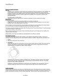
1
ESABASE2 - Sunlight Software User Manual Contract No: 16852/02/NL/JA Title: PC Version of DEBRIS Impact Analysis Tool ESA Technical Officer: G. Drolshagen, J. Sørensen Prime Contractor: etamax space GmbH Authors: K.Ruhl, A.Gaede Date: 2009-12-14 Reference: R077-235rep_01_01_Software_User_Manual_Solver_Sunlight.doc Revision: 1.1 Status: Final Confidentiality: etamax space GmbH Richard-Wagner-Str. 1 D-38106 Braunschweig Germany Tel.: +49 (0)531.3802.404 Fax: +49 (0)531.3802.401 email: [email protected] http://www.etamax.de © etamax space GmbH Table of Contents Document Information .......................................................................................... 3 I. Release Note .................................................................................................. 3 II. Revision History .............................................................................................. 3 III. Distribution List .............................................................................................. 3 IV. List of References ........................................................................................... 4 V. Glossary .......................................................................................................... 5 VI. List of Abbreviations ...................................................................................... 5 VII. List of Figures ................................................................................................. 6 1 Introduction...................................................................................................... 7 2 Sunlight Solver ................................................................................................. 8 2.1 Sunlight Geometry ......................................................................................... 8 2.1.1 Material Page ..................................................................................................... 9 2.1.2 Meshing page ................................................................................................... 11 2.2 Sunlight Input .............................................................................................. 12 2.2.1 Sun and Planet tab ........................................................................................... 13 2.2.2 Raytracing and Thermo-optical properties tab ............................................... 16 2.2.3 Analysis tab....................................................................................................... 19 2.3 Sunlight Analysis .......................................................................................... 21 2.4 Sunlight Results ............................................................................................ 23 2.4.1 3D Results tab ................................................................................................... 24 2.4.2 Element Charts ................................................................................................. 26 2.4.3 Listings tab........................................................................................................ 28 2.4.4 Notes tab .......................................................................................................... 29 Date: 2009-12-14 Revision 1.1 State: Final Page 2 / 29 ESABASE2 - Sunlight Software User Manual Reference: R077-235rep_01_01_Software_User_Manual_Solver_Sunlight.doc etamax space GmbH . Richard-Wagner-Straße 1 . 38106 Braunschweig Document Information I. Release Note Established by: Released by: Name Function Date Signature K.Ruhl Technical Project Manager 2009-12-14 signed K.Ruhl K.D. Bunte Project Manager 2009-11-25 signed K.Bunte II. Revision History Version Date Initials Changed Reason for Revision 0.1 2009-08-03 KR All Split from common ESABASE2 handbook. 0.2 2009-10-27 KR Chapter 2 Structure and screenshots for all. 0.5 2009-11-11 AG All Missing information added, review. 1.0 2009-11-25 KR All Reviewed and finalised. 1.1 2009-12-14 KR Section 2.1 Added pos/neg active side information. III. Distribution List Institution Name ESTEC Gerhard Drolshagen ESTEC John Sørenson diverse n/a Remarks ESABASE2 licensees ESABASE2 - Sunlight Date: Software User Manual Revision: Reference: R077-235rep_01_01_Software_User_Manual_Solver_Sunlight.doc State: etamax space GmbH . Richard-Wagner-Straße 1 . 38106 Braunschweig 2009-12-14 1.1 Final Page 3 / 29 IV. List of References /1/ K.Ruhl, K.Bunte, ESABASE2/Framework software user manual, R077-230rep, ESA/ESTEC Contract 16852/02/NL/JA "PC Version of DEBRIS Impact Analysis Tool", etamax space, 2009 /2/ ESABASE2 homepage, http://www.esabase2.net/ /3/ SWENET, ESA's Space Weather European Network, since 2004, http://www.esa-spaceweather.net/swenet/ /4/ ESABASE User Manual, ESABASE/GEN-UM-070, Issue 1, Mathematics & Software Division, ESTEC, March 1994 /5/ ESABASE/Sunlight Application Manual, ESABASE/SUN-UM-072 Issue 2, Technology/CAE Department, Dornier GmbH, Germany, September 1994 /6/ P. Rosenthal, F. Zilly, W. Keil, ESABASE/Sunlight Software Design Document, Version 2.0, Date 94/08/25, Dornier GmbH, Germany, August 1994 Date: 2009-12-14 Revision 1.1 State: Final Page 4 / 29 ESABASE2 - Sunlight Software User Manual Reference: R077-235rep_01_01_Software_User_Manual_Solver_Sunlight.doc etamax space GmbH . Richard-Wagner-Straße 1 . 38106 Braunschweig V. Glossary Term Description Application ESABASE application such as e.g. the "Debris" or the "Sun light" application. Eclipse Eclipse is an open source community whose projects are focused on providing an extensible development platform and application frameworks for building software. For detailed information refer to http://www.eclipse.org/. ESABASE Unix-based analysis software for various space applications. For details refer to the ESABASE User Manual /4/. ESABASE2 New ESABASE version running on PC-based Windows platforms (to be distinguished from the "old" Unix-based ESABASE). STEP Acronym which stands for the Standard for the Exchange of Product model data. VI. List of Abbreviations Abbreviation Description GUI Graphical User Interface JVM Java Virtual Machine NASA National Astronautics and Space Administration OCAF Open CASCADE Application Framework (contains the ESABASE2 data model) ESABASE2 - Sunlight Date: Software User Manual Revision: Reference: R077-235rep_01_01_Software_User_Manual_Solver_Sunlight.doc State: etamax space GmbH . Richard-Wagner-Straße 1 . 38106 Braunschweig 2009-12-14 1.1 Final Page 5 / 29 VII. List of Figures Figure 2.1: Geometry editor, Material page, Atmosphere/Ionosphere .......................... 9 Figure 2.2: Geometry editor, Meshing page.................................................................. 11 Figure 2.3: Sunlight input editor.................................................................................... 12 Figure 2.4: Sunlight input editor, Sun and Planet tab .................................................. 13 Figure 2.5: Sunlight input editor, Thermo optical properties tab ................................ 16 Figure 2.6: Sunlight input editor, Raytracing tab .......................................................... 17 Figure 2.7: Sunlight input editor, Analysis tab .............................................................. 19 Figure 2.8: Sunlight analysis, Run button ...................................................................... 21 Figure 2.9: Sunlight analysis, Run wizard ...................................................................... 21 Figure 2.10: Sunlight result editor ................................................................................... 23 Figure 2.11: Sunlight result editor, 3D results tab ........................................................... 24 Figure 2.12: Sunlight result editor, 3D results tab, Element chart context menu .......... 26 Figure 2.13: Sunlight result editor, 3D results tab, Element chart .................................. 26 Figure 2.14: Sunlight result editor, Listings tab............................................................... 28 Figure 2.15: Sunlight result editor, Notes tab ................................................................. 29 Date: 2009-12-14 Revision 1.1 State: Final Page 6 / 29 ESABASE2 - Sunlight Software User Manual Reference: R077-235rep_01_01_Software_User_Manual_Solver_Sunlight.doc etamax space GmbH . Richard-Wagner-Straße 1 . 38106 Braunschweig 1 Introduction ESABASE2 is a software application (and framework) for space environment analyses, which play a vital role in spacecraft mission planning. Currently, it encompasses Debris/Meteroid, Atmosphere/Ionosphere, Sunlight and Contamination/Outgassing analyses; with this, it complements other aspects of mission planning like thermal or power design. The application grew from ESABASE2/Debris, an application for space debris and micrometeoroid impact and damage analysis, which in turn is based on the original ESABASE/Debris software developed by the European Space Agency. ESABASE2 adds a modern graphical user interface enabling the user to interactively establish and manipulate three-dimensional spacecraft models and to display the selected orbit. Analysis results can be displayed by means of the colour-coded surfaces of the 3D spacecraft model, and by means of various diagrams. The development of ESABASE2 was undertaken by etamax space GmbH under the European Space Agency contract No. 16852/02/NL/JA. The first goal was to port ESABASE/Debris and its framework/user interface to the PC platform (Microsoft Windows) and to create a modern user interface. From the start, the software architecture has been expressively designed to accommodate further applications: the solvers outlined in the first paragraph were added, and more modules like radiation are to follow. ESABASE2 is written in Fortran 77, ANSI C++ and Java 6. The GUI is built on top of the Eclipse rich client platform, with 3D visualisation and STEP import realised by Open CASCADE. Report and graphs are based on the JFreeReport/JFreeGraph libraries. This user manual is the Sunlight handbook. It complements the Framework user manual /1/, which explains the common functionality of all solvers (e.g. Debris, Sunlight, Atmosphere/Ionosphere, or COMOVA). ESABASE2 - Sunlight Date: Software User Manual Revision: Reference: R077-235rep_01_01_Software_User_Manual_Solver_Sunlight.doc State: etamax space GmbH . Richard-Wagner-Straße 1 . 38106 Braunschweig 2009-12-14 1.1 Final Page 7 / 29 2 Sunlight Solver SUNLIGHT is a solver for analyses on spacecraft and missions defined within the ESABASE2 framework /1/. This handbook assumes you already have a spacecraft geometry and mission input file at hand, and now want to perform a Sunlight analysis. Towards this purpose, this chapter is split into four sections: Sunlight Geometry: How to adapt your spacecraft geometry such that the shapes possess the required input parameters. Sunlight Input: Describes the global Sunlight input parameters (those that are not directly pertinent to the geometry). Sunlight Analysis: How to run a Sunlight analysis. Sunlight Results: How to interpret the results of a Sunlight analysis. 2.1 Sunlight Geometry Sunlight relies mostly on the common spacecraft geometry description. There is no dedicated Sunlight page in the geometry wizard; however, some pages are of special interest. Material Page: The Sunlight solver uses settings from the material page. Meshing Page: Positive/negative sides and meshing recommendations. The following subsections cover these Wizard pages. Date: 2009-12-14 Revision 1.1 State: Final Page 8 / 29 ESABASE2 - Sunlight Software User Manual Reference: R077-235rep_01_01_Software_User_Manual_Solver_Sunlight.doc etamax space GmbH . Richard-Wagner-Straße 1 . 38106 Braunschweig 2.1.1 Material Page Sunlight interprets material definitions on the spacecraft. To define material surfaces, select an object in the geometry editor, rightclick to open the context menu, and choose "Modify Material". The wizard shown in the figure below will open. Figure 2.1: Geometry editor, Material page, Atmosphere/Ionosphere Materials specified in the material wizard page are used for multiple solvers (Atmosphere, Sunlight, etc.). Therefore, their attributes may vary. Take care to select only materials with material properties relevant to Sunlight, by setting the filter to Sunlight, as shown in the figure above (see also /1/ for more on the material wizard). ESABASE2 - Sunlight Date: Software User Manual Revision: Reference: R077-235rep_01_01_Software_User_Manual_Solver_Sunlight.doc State: etamax space GmbH . Richard-Wagner-Straße 1 . 38106 Braunschweig 2009-12-14 1.1 Final Page 9 / 29 In particular, the Sunlight relevant material properties are: range default no full alpha: solar absorptivity 0..1 1 0 1 epsilon: infrared emissivity 0..1 1 0 1 taua: direct solar transmissivity 0..1 0 0 1 taue: direct infrared transmissivity 0..1 0 0 1 tauad: diffuse transmissivity of solar radiation 0..1 0 0 1 taued: diffuse transmissivity of infrared radiation 0..1 0 0 1 range default diffuse specular speca: specularity ratio for reflection of solar radiation 0..1 0 0 1 spece: specularity ratio for reflection of infrared radiation 0..1 0 0 1 Date: 2009-12-14 Revision 1.1 State: Final Page 10 / 29 ESABASE2 - Sunlight Software User Manual Reference: R077-235rep_01_01_Software_User_Manual_Solver_Sunlight.doc etamax space GmbH . Richard-Wagner-Straße 1 . 38106 Braunschweig 2.1.2 Meshing page Although the meshing page (shown below) is the same for all solvers, the effects of the settings may vary. Figure 2.2: Geometry editor, Meshing page Subdivision of surfaces (i.e. "surface nodes") are supported by Sunlight, provided you choose the "Surface" results in the analysis tab of the Sunlight input editor (see 2.2.3). Regarding active sides: If you use "Surface", results can be shown for both sides of the elements separately. If you use "Element" or "Object" setting, the results for both sides are summed up. For volumes, this is uncritical, because only one side is ever affected. For surfacic shapes (e.g. plate), we recommend choosing only one active side, because the results can otherwise not be correctly assigned to an element side. All other Sunlight input parameters are defined in the Sunlight input file, which we handle in the following section. ESABASE2 - Sunlight Date: Software User Manual Revision: Reference: R077-235rep_01_01_Software_User_Manual_Solver_Sunlight.doc State: etamax space GmbH . Richard-Wagner-Straße 1 . 38106 Braunschweig 2009-12-14 1.1 Final Page 11 / 29 2.2 Sunlight Input All global Sunlight parameter settings are done in the Sunlight input editor, as shown in the figure below. To create a Sunlight input file, choose "File New Sunlight". Figure 2.3: Sunlight input editor Within the editor, the following tabs are available: Sun and Planet: To specify parameters for the Sun and the planet that the spacecraft is orbiting. In particular you set here how solar radiation behaves at the place where it is emitted (Sun) and where it is reflected (planet). Raytracing and Thermo-optical properties: Thermo-optical properties enable sunlight to consider temperature and wavelength dependencies. Raytracing parameters are necessary for the raytracing algorithm that is calculating the radiative flux on the geometry. Analysis: To define the sources of radiation (e.g. direct Sun, indirect planet albedo, etc.) considered in the analysis and to set output options for the result file. Date: 2009-12-14 Revision 1.1 State: Final Page 12 / 29 ESABASE2 - Sunlight Software User Manual Reference: R077-235rep_01_01_Software_User_Manual_Solver_Sunlight.doc etamax space GmbH . Richard-Wagner-Straße 1 . 38106 Braunschweig 2.2.1 Sun and Planet tab The Sun and Planet tab is separated into two sections. In the Sun section you can specify several parameters for the Sun. In the second section four parameters of the planet that is surrounded by the satellite can be defined. The parameters of the Earth are set as default. Figure 2.4: Sunlight input editor, Sun and Planet tab In the Sun section, the following parameters are available: Radius of the Sun: This parameter gives the radius for the surface of the sun where the solar radiation is emitted. It is necessary for all three solar spectrum types. Solar spectrum type: The selected solar spectrum type is valid at the surface where the solar radiation is emitted. This surface is defined by the radius of the sun (see previous parameter). You can select between three types of solar spectra. o THERMAL uses a constant value as spectrum parameter, the so called solar constant at the vicinity of the Earth. It is completely independent from wavelength and temperature. o BLACKBODY applies Planck’s radiation energy density formula; the spectrum is parameterised with respect to temperature and a wavelength range. "Blackbody radiation" refers to an object or system which absorbs all radiation incidents upon it and re-radiates energy which is characteristic of this radiating system only, not dependent upon the type of radiation which is incident upon it (e.g. all planets have a re-radiation "signature"). ESABASE2 - Sunlight Date: Software User Manual Revision: Reference: R077-235rep_01_01_Software_User_Manual_Solver_Sunlight.doc State: etamax space GmbH . Richard-Wagner-Straße 1 . 38106 Braunschweig 2009-12-14 1.1 Final Page 13 / 29 o USER allows to supply a user defined solar spectrum stored in a separate file (*.SSF). Here you can specify your own wavelength dependent values. Solar constant at the vicinity of the planet: This parameter is only necessary for the solar spectrum type "THERMAL" and gives the solar constant at the vicinity of the planet. Temperature of the Blackbody surface: Defines the temperature for the blackbody surface that is necessary for the solar spectrum type "BLACKBODY". Distance to geometry centre: For the solar spectrum type “BLACKBODY” radius of the Sun and distance to geometry centre are used for scaling the emitted radiation from the solar/blackbody radiation source. You can specify the distance between centre of solar/blackbody radiation source and system geometry centre. This makes only sense if you consider a sun synchronous orbit where the distance is roughly invariant. When setting distance to geometry centre to -1 it will be updated at each orbital point with the actual distance to sun centre. Lower value at wavelength range: You can set the lower value of the wavelength range ("blue end") considered in spectral integration. It is used for solar spectrum type BLACKBODY and USER. Setting it to -1 requests SUNLIGHT to evaluate the longest wavelength compatible with all supplied spectra and types. Upper value at wavelength range: You can set the upper value of the wavelength range ("red end") considered in spectral integration. It is used for solar spectrum type BLACKBODY and USER. Setting it to -1 requests SUNLIGHT to evaluate the smallest wavelength compatible with all supplied spectra and types. Scaling factor for user supplied solar spectrum: You can set a scaling factor for USER supplied solar spectrum. It can be used in case of terrestrial irradiation source to simulate switching on/off individual illumination sources. Solar spectrum file: A user defined solar spectrum file can be selected for the solar spectrum type “USER”. You can define here your specific solar spectrum. The preferred extension is "*.SSF". Only for advanced users. Below, in the Planet section, the following parameters are available: Radius of the planet: The default value for the planet radius is the Earth radius. But it is also feasible to make a sunlight simulation with a different radius. It affects the visibility of the planet albedo and planet infrared radiation. But keep in mind that the specified radius does not affect the orbit generation algorithm. Planet albedo factor: You can specify the planet albedo factor that gives the fraction of the radially reflected solar radiation relative to the solar irradiation. The larger this value is the larger is the radiation part of Planet albedo. Temperature of planet surface at the sub-solar point for planet infrared radiation: You can specify the temperature of the Earth surface at the sub-polar point (where the sun is directly over head) of Earth infrared radiation. Sunlight internally considers angular variation from sub-polar point to day-night terminator due to non radial line of sight and Earth surface temperature variation. Date: 2009-12-14 Revision 1.1 State: Final Page 14 / 29 ESABASE2 - Sunlight Software User Manual Reference: R077-235rep_01_01_Software_User_Manual_Solver_Sunlight.doc etamax space GmbH . Richard-Wagner-Straße 1 . 38106 Braunschweig Effective temperature of the planet surface for all points on the planet night side: For Earth infrared radiation you can specify the (effective) temperature of the Earth surface for all points on the Earth night side. For this side any temperature variation is neglected. The Earth surface temperature at day-night zone transition is considered as continuous. ESABASE2 - Sunlight Date: Software User Manual Revision: Reference: R077-235rep_01_01_Software_User_Manual_Solver_Sunlight.doc State: etamax space GmbH . Richard-Wagner-Straße 1 . 38106 Braunschweig 2009-12-14 1.1 Final Page 15 / 29 2.2.2 Raytracing and Thermo-optical properties tab The raytracing and thermo-optical properties tab is again separated into two sections. In the first section the thermo-optical properties (T.O.P.) can be defined and in the second several raytracing parameters can be set. The figure below shows the thermooptical properties. Figure 2.5: Sunlight input editor, Thermo optical properties tab The following T.O.P. parameters are available: Spectrum type for thermo-optical properties: With this combobox you can switch between THERMAL = standard thermo-optical properties defined in the material wizard (see core user manual /1/) and USER = thermo-optical properties that depend on the wavelength of the radiation. It is defined in a separate file that is selectable with the next parameter. User-defined T.O.P. file: You can select with the Browse button a so called *.TSF file that contains the user defined wavelength dependent T.O.P. In the second part, you can modify the raytracing behaviour. Raytracing settings can significantly influence the runtime of a Sunlight analysis Ray tracing is used for the calculation of radiative flux. The number of fired rays is essential for that algorithm. Depending on the conditions of the geometry, e.g. many objects where one shadows the other, the number of rays should be increased. The figure below shows the raytracing part of the tab. Date: 2009-12-14 Revision 1.1 State: Final Page 16 / 29 ESABASE2 - Sunlight Software User Manual Reference: R077-235rep_01_01_Software_User_Manual_Solver_Sunlight.doc etamax space GmbH . Richard-Wagner-Straße 1 . 38106 Braunschweig Figure 2.6: Sunlight input editor, Raytracing tab The following options are available: General: Total number of fired rays gives the possibility to set the number of rays relative to the element area. The larger an element is the more rays are fired compared to smaller elements You can specify a minimum number of rays that are fired at least from each element. Seed for random number generator: This number initialises the random number generator that is necessary for the ray tracing. As long as it remains unchanged always the same sequence of random numbers are generated. The calculated results depend on this value due to imperfections in the distribution of the random number generation. This dependency decreases with increasing number of fired rays. Select a value between 0 and 1. Multiple emission: Number of absolute propagation orders: This number defines how many times a reflection and/or transmission will be calculated for a ray. A value between 1 and 50 is feasible. A larger number will increase the computation time. Zero disables the multi emission algorithm. Ray extinction threshold: This threshold defines the stop criteria (in 100% of the direct irradiation) to stop the multiple emission for that ray. The remaining radiative flux is summed in an error variable (displayed in the report file). ESABASE2 - Sunlight Date: Software User Manual Revision: Reference: R077-235rep_01_01_Software_User_Manual_Solver_Sunlight.doc State: etamax space GmbH . Richard-Wagner-Straße 1 . 38106 Braunschweig 2009-12-14 1.1 Final Page 17 / 29 Reflection parameters: If a ray is reflected, it is split into multiple other rays. o Specular reflection is only for one ray. The propagation order determines how many times this particular ray can be reflected. o Diffuse reflection splits the incoming ray into many reflected rays. Again, propagation order determines how often these rays can be further reflected. o For diffuse rays, you can also specify how many diffuse rays are reflected per incoming ray. Transmission parameters: Similar to reflection, but instead of reflecting away from a body, the rays propagate inside that body (e.g. glass). Instead of one specular ray, the ray just goes straight through the material. As for the absolute propagation orders a value between 1 and 50 is feasible and zero disables the specific emission type. Relative propagation orders should be between 1 and 10. The absolute propagation orders limit the relative propagation orders, if the relative propagation orders are larger than the absolute propagation orders. In addition you can specify for both diffuse reflection and diffuse transmission the number of fired rays. The default value is 100 but any other value is feasible. Date: 2009-12-14 Revision 1.1 State: Final Page 18 / 29 ESABASE2 - Sunlight Software User Manual Reference: R077-235rep_01_01_Software_User_Manual_Solver_Sunlight.doc etamax space GmbH . Richard-Wagner-Straße 1 . 38106 Braunschweig 2.2.3 Analysis tab In the analysis tab, you can specify which results you want to have as output of the Sunlight run, as depicted in the figure below. Further on you can specify what sources and/or combinations of them shall be considered during the analysis. Figure 2.7: Sunlight input editor, Analysis tab The following analysis parameters are available: Output step sequence for orbital points: You can omit orbital points. In a result file, the orbital arc and mission summary are always generated. E.g. setting the parameter to 3 generates results for the 1., 3., 6., 9., .. orbital points. Zero suppresses all and 1 generates output for all orbital points. Data type to be stored in the result file: The analysis results can be stored for different geometry detail levels. You can select between "Element", "Surface" and "Object". For "Element" and "Object" you get the results on element resp. object level. If "Surface" is selected, you get the results on surface node level (see /1/ for more details). Data type to be stored in the report file: See previous parameter, except that it applies to the LISTING file, not to the 3D geometry overlay, and that only "Surface" or "Object" are selectable. ESABASE2 - Sunlight Date: Software User Manual Revision: Reference: R077-235rep_01_01_Software_User_Manual_Solver_Sunlight.doc State: etamax space GmbH . Richard-Wagner-Straße 1 . 38106 Braunschweig 2009-12-14 1.1 Final Page 19 / 29 Enclosure selection: It is possible to analyse specific parts (called enclosures) of the geometry. These Enclosures have to be specified first in the geometry. Specify here the number of the Enclosure to be analysed. In the "Sources" section, you can also specify whether direct/indirect rays, and whether Sun/Albedo/Planet infrared rays shall be considered in the analysis, and combination of both. The following points are to be considered: Six different basic sources exist (direct and indirect Sun, direct and indirect Planet albedo, direct and indirect Planet infrared). The other twelve selectable sources are combinations of the six basic sources. Direct irradiation is that part of radiation being incident upon a point which stems from sources external to the system under study (i.e. Sun shining on Earth in the default case). Indirect irradiation results from the multiple emission process (see 2.2.2). It could be caused by reflection or transmission of the direct irradiation and depends on the material properties of the geometry. Planet albedo is the radiation of the sun that is reflected by the planet. Its value depends on the planet albedo factor. Planet infrared is the infrared radiation emitted by the Earth. Date: 2009-12-14 Revision 1.1 State: Final Page 20 / 29 ESABASE2 - Sunlight Software User Manual Reference: R077-235rep_01_01_Software_User_Manual_Solver_Sunlight.doc etamax space GmbH . Richard-Wagner-Straße 1 . 38106 Braunschweig 2.3 Sunlight Analysis When you have spacecraft geometry, mission and Sunlight input file ready, then locate the Sunlight run button shown in the figure below. Press it on the right side and choose "Run Sunlight Analysis". Figure 2.8: Sunlight analysis, Run button A wizard similar to the other solver wizards will appear, in which you first select one of the projects in your workspace, and then geometry, mission, and Sunlight input file from that project, as shown in the figure below. Figure 2.9: Sunlight analysis, Run wizard In the lower part, you can specify the name of the output file. We recommend choosing a name that makes the file uniquely identifiable; as a first proposal, the "sunlight" label and the current date and time are given. ESABASE2 - Sunlight Date: Software User Manual Revision: Reference: R077-235rep_01_01_Software_User_Manual_Solver_Sunlight.doc State: etamax space GmbH . Richard-Wagner-Straße 1 . 38106 Braunschweig 2009-12-14 1.1 Final Page 21 / 29 Above the textfield for the output file name, there are two options: Only preprocessing Slim results If you choose only preprocessing, the Sunlight analysis will not occur. Instead, the pointing and kinematics will be checked; if for some reason pointing and kinematics can not be fulfilled, you will get a warning. For large result files, you can choose "Slim results". This will reduce the file size of the output file considerably, because no orbital point geometries will be saved. Therefore, you are only able to view mission and orbital arc results in the output file. Press "Finish" to start the analysis. A progress bar will appear and keep you updated about the status of the analysis. At its end, the Sunlight result editor will open, as shown in the next section. Date: 2009-12-14 Revision 1.1 State: Final Page 22 / 29 ESABASE2 - Sunlight Software User Manual Reference: R077-235rep_01_01_Software_User_Manual_Solver_Sunlight.doc etamax space GmbH . Richard-Wagner-Straße 1 . 38106 Braunschweig 2.4 Sunlight Results At the end of a Sunlight analysis, an output file (with the file name given by you in the Run wizard) will be created, and the Sunlight output editor will be opened, as shown in the figure below. Figure 2.10: Sunlight result editor The result editor has three tabs: 3D Results: Shows the spacecraft geometry with different values overlaid. Element charts can be called from this tab. Listings: Shows the LIS files as produced by the original ESABASE /4/. Notes: Text area for your own notes. ESABASE2 - Sunlight Date: Software User Manual Revision: Reference: R077-235rep_01_01_Software_User_Manual_Solver_Sunlight.doc State: etamax space GmbH . Richard-Wagner-Straße 1 . 38106 Braunschweig 2009-12-14 1.1 Final Page 23 / 29 2.4.1 3D Results tab In the 3D Results tab, you can see the spacecraft geometry, overlaid initially with the element number, as shown in the figure below (notice the colour scale to the right). To change the overlay value, rightclick into the editor, then choose "Colour [Desired Quantity]". Figure 2.11: Sunlight result editor, 3D results tab Unlike the other (e.g. Debris, Atmosphere) solvers, the number of entries below "Colour" varies according to the analysis options chosen in the Sunlight input file (see 2.2.3). Only the following options are fixed: Object colour: If you specified colours in the spacecraft geometry editor, these are shown now. Useful if you want to detect a certain small component in a much larger model. Object number: All geometrical shapes of the spacecraft are simply numbered, and assigned a different colour. Evident by the colour scale on the right. Surface number: Every object has one or more surfaces; surface numbering is more detailed than object numbering. Element number: Even more detailed than surface numbering (every surface has one or more elements); e.g. in the figure above, you can see at the top of the colour scale that the geometry has 800 elements. The other analysis results depend on the selected result type (ELEMENT, SURFACE or OBJECT). The name of these results include a combination of the result value, the selected source (see 2.2.3) and, for ELEMENT and SURFACE, front or back side. Date: 2009-12-14 Revision 1.1 State: Final Page 24 / 29 ESABASE2 - Sunlight Software User Manual Reference: R077-235rep_01_01_Software_User_Manual_Solver_Sunlight.doc etamax space GmbH . Richard-Wagner-Straße 1 . 38106 Braunschweig The result values depend on whether it is an orbital point or an orbital arc resp. mission output. They have the following names: Result column in report file Orbital point Orbital arc / mission 1 Illumination factor (100%) Exposure time (hrs) 2 Relative illumination factor (100%) Effective fluence (hrs) 3 Incident power (W/m²) Incident energy (W/m²) 4 Absorbed power (W/m²) Absorbed energy (W/m²) The source name part is given by the following possibilities (and combinations thereof, 18 in sum): … of direct Sun. … of direct planet Albedo. … of direct planet Infrared. … of indirect Sun. … of indirect planet Albedo. … of indirect planet Infrared. These combinations of result value and source value can be given for both positive and negative sides of the geometry elements and surfaces. This is indicated with pos (front side) or neg (back side) at the end of the result name, e.g. “Illumination_factor_of_direct_Sun_pos”. Object results do not have this annex. By default, the editor shows the values for the entire mission. To select single orbital points or an orbital arc, open the context menu by rightclick on the geometry and choose "Orbital Point Orbital Point n" or "Orbital Point Orbital arc". In an orbital point, the correct pointing will be shown (e.g. solar panels pointing to the sun); this is omitted for mission or orbital arc. Please note that orbital points and orbital arc are not accessible if you chose "Slim results" in the Run wizard. ESABASE2 - Sunlight Date: Software User Manual Revision: Reference: R077-235rep_01_01_Software_User_Manual_Solver_Sunlight.doc State: etamax space GmbH . Richard-Wagner-Straße 1 . 38106 Braunschweig 2009-12-14 1.1 Final Page 25 / 29 2.4.2 Element Charts The geometry overlay values give a good overview over Sunlight effects on the analysed spacecraft. Going into detail, you can see effects on a single element of the spacecraft, as shown in the figure below. Figure 2.12: Sunlight result editor, 3D results tab, Element chart context menu Shift+click on an element on screen to select a single element of the geometry. Then rightclick and choose "Element Chart" from the context menu. A new window will open, similar to the one pictured below. Figure 2.13: Sunlight result editor, 3D results tab, Element chart Date: 2009-12-14 Revision 1.1 State: Final Page 26 / 29 ESABASE2 - Sunlight Software User Manual Reference: R077-235rep_01_01_Software_User_Manual_Solver_Sunlight.doc etamax space GmbH . Richard-Wagner-Straße 1 . 38106 Braunschweig Initially, the graph area is empty, and you have to select a value from the combobox at the top. The choices are the same as for the 3D geometry colors; here in the graph, the progression of the value over the orbital points is shown. To the right of the combobox, you can see two buttons: "Options" and "Export Image". Within the options, you can change the scaling and various other settings for the graph below. Choosing "Export Image" allows you to export the currently displayed graph to PNG or JPG format. The image will take on the dimensions and appearance of the currently existing graph. ESABASE2 - Sunlight Date: Software User Manual Revision: Reference: R077-235rep_01_01_Software_User_Manual_Solver_Sunlight.doc State: etamax space GmbH . Richard-Wagner-Straße 1 . 38106 Braunschweig 2009-12-14 1.1 Final Page 27 / 29 2.4.3 Listings tab Users of the original ESABASE /4/ will feel familiar with the LIS files displayed in the Listings tab shown in the Figure below. LIS files are text reports of the analysis, and were the primary output mechanism in the original ESABASE. Figure 2.14: Sunlight result editor, Listings tab In the combobox at the top, you can select the listing file to be displayed. The following options are available: Sunlight results: The results as selected in the analysis section of the Sunlight input file (see 2.2.3). Orbit data: Information about the orbital points. Kinematic data: Pointing and kinematic information. Because the files are reports, they provide some information about their interpretation. For more detail, please see the user manual of the original ESABASE /4/. Date: 2009-12-14 Revision 1.1 State: Final Page 28 / 29 ESABASE2 - Sunlight Software User Manual Reference: R077-235rep_01_01_Software_User_Manual_Solver_Sunlight.doc etamax space GmbH . Richard-Wagner-Straße 1 . 38106 Braunschweig 2.4.4 Notes tab At the left end of the tabs within the Sunlight result editor, you can find the Notes tab. It is a simple text editor in which you can enter any notes, as shown in the figure below. Figure 2.15: Sunlight result editor, Notes tab When you edit the text, an asterisk ("*") besides the editor label (top left in the figure above) appears, as usual when a file is changed. Saving the file will also save your notes. ESABASE2 - Sunlight Date: Software User Manual Revision: Reference: R077-235rep_01_01_Software_User_Manual_Solver_Sunlight.doc State: etamax space GmbH . Richard-Wagner-Straße 1 . 38106 Braunschweig 2009-12-14 1.1 Final Page 29 / 29