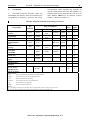
1
Chapter 25 – Machinery Condition Monitoring
2015
Unless otherwise specified, these Rules apply to ships for which the date of contract for
construction as defined in IACS PR No.29 is on or after 01st January 2015. New rules or
amendments entering into force after the date of contract for construction are to be applied
if required by those rules. See Rule Change Notices on TL website for details.
"General Terms and Conditions" of the respective latest edition will be applicable (see
Rules for Classification and Surveys).
If there is a difference between the rules in English and in Turkish, the rule in English is to
be considered as valid. This publication is available in print and electronic pdf version.
Once downloaded, this document will become UNCONTROLLED. Please check
www.turkloydu.org for the amended and valid version.
All rights are reserved by Türk Loydu, and content may not be reproduced, disseminated,
published, or transferred in any form or by any means, except with the prior written
permission of TL.
TÜRK LOYDU
Head Office
Postane Mah. Tersaneler Cad. No:26 Tuzla 34944 İSTANBUL / TÜRKİYE
Tel
: (90-216) 581 37 00
Fax
: (90-216) 581 38 00
E-mail
: [email protected]
http://www.turkloydu.org
Regional Offices
Ankara
İzmir
Adana
Eskişehir Yolu Mustafa Kemal Mah. 2159. Sokak No : 6/4 Çankaya - ANKARA / TÜRKİYE
Tel
: (90-312) 219 56 34
Fax
: (90-312) 219 68 25
E-mail
: [email protected]
Atatürk Cad. No :378 K.4 D.402 Kavalalılar Apt. 35220 Alsancak - İZMİR / TÜRKİYE
Tel
: (90-232) 464 29 88
Fax
: (90-232) 464 87 51
E-mail
: [email protected]
Çınarlı Mah. Atatürk Cad. Aziz Naci İş Merkezi No:5 K.1 D.2 Seyhan - ADANA / TÜRKİYE
Tel
: (90- 322) 363 30 12
Fax
: (90- 322) 363 30 19
E-mail
Marmaris
: [email protected]
Atatürk Cad. 99 Sok. No:11 Kat:4 Daire 6
Tel
: (90- 252) 412 46 55
Fax
: (90- 252) 412 46 54
E-mail
: [email protected]
Marmaris - MUĞLA / TÜRKİYE
Contents
Machinery Condition Monitoring
Page
Section 1 - General
A.
General ...................................................................................................................................................... 1- 2
B.
Definitions .................................................................................................................................................. 1- 2
C.
Documents to be Submitted ....................................................................................................................... 1- 4
D.
Survey Arrangement .................................................................................................................................. 1- 5
E.
Planned Maintenance System ................................................................................................................... 1- 5
Section 2 - Requirements for the Design of Condition Monitoring Systems
A.
General Requirements ............................................................................................................................... 2- 2
B. Requirements for Installation ..................................................................................................................... 2- 2
C. Requirements for Software ........................................................................................................................ 2- 3
D. Steps of Acceptance .................................................................................................................................. 2- 3
Section 3 - Requirements for Operation
A.
Operating Personnel .................................................................................................................................. 3- 2
B.
Measurements ........................................................................................................................................... 3- 2
C.
Analysis ..................................................................................................................................................... 3- 2
D.
Reporting .................................................................................................................................................... 3- 3
E.
Documents available on Board ................................................................................................................... 3- 3
Section 4 - Surveys
A.
General ...................................................................................................................................................... 4- 2
B.
Implementation Survey .............................................................................................................................. 4- 2
C.
Final Approval ............................................................................................................................................ 4- 2
D.
Annual Survey ........................................................................................................................................... 4- 2
E.
Non-periodical Surveys .............................................................................................................................. 4- 2
Annex A - Examples for Application
A.
Scope ........................................................................................................................................................ A- 2
B.
Cranktrain Bearings of Low-speed Diesel Engines ..................................................................................... A- 2
C.
Centrifugal Pumps ..................................................................................................................................... A- 2
D.
Accumulator Battery .................................................................................................................................. A- 4
Annex B - Standards for Lubricating Oil Analysis
A.
Test Methods .............................................................................................................................................. B- 2
Section 1 – General
1-1
SECTION 1
GENERAL
Page
A.
GENERAL ......................................................................................................................................................... 1- 2
1. Scope
2. Purpose
3. Structure of Condition Monitoring Systems
4. Equivalence
B.
DEFINITIONS .................................................................................................................................................... 1- 2
1. Baseline Data
2. Condition Based Maintenance
3. Condition Based Survey
4. Condition Monitoring
5. Condition Monitoring Equipment
6. Condition Monitoring System
7. Condition Monitoring Method
8. Machinery Component
9. Machinery System
10. Planned Maintenance System (PMS)
11. Reference Conditions
12. Reference Values
13. Trend Analysis
C.
DOCUMENTS TO BE SUBMITTED .................................................................................................................. 1- 4
1. General
2.
Scope of Documentation
D.
SURVEY ARRANGEMENT ............................................................................................................................... 1- 5
E.
PLANNED MAINTENANCE SYSTEM .............................................................................................................. 1- 5
TÜRK LOYDU - MACHINERY CONDITION MONITORING - 2015
Section 1 – General
1-2
A.
A,B
of producing relevant data trends from the values
General
collected
1.
Scope
1.1
These
and
compare
them
with
pre-defined
acceptance criteria (e.g. limit curves).
Guidelines
for
Machinery
Condition
Condition
2.3
Monitoring
for
a
Machinery
Monitoring apply to the machinery of ships, which are
Component, or parts of it, will be accepted by TL, if it is
classified by TL, and for which a Survey Arrangement
capable
CM has been concluded between the owner/operator of
information for determining the actual condition of the
the ship and TL.
Machinery Component, or parts of it.
1.2
These Guidelines can be applied to new ships
2.4
of
producing
reliable
and
trustworthy
The condition determination of a Machinery
and to existing ships. For already existing ships, for
Component or parts of it, achieved from a TL accepted
which a Survey Arrangement CM will be requested,
Condition
special considerations concerning their actual wear and
equivalent
tear condition have to be undertaken.
inspection, compare Section 4.
1.3
These Guidelines apply in addition to the TL
3.
Monitoring
to
System,
condition
will
be
determination
considered
by
direct
Structure of Condition Monitoring Systems
Rules for Classification and Construction.
Condition Monitoring Systems are distinguished in three
1.4
The
Guidelines
set
out
TL's
general
categories:
requirements regarding Condition Monitoring, which are
the basis for the acceptance of Condition Monitoring
−
fixed installed systems
−
systems with portable measurement equipment
−
sampling systems, e.g. for oil sampling
4.
Equivalence
with respect to Condition Based Survey.
1.5
If a Condition Monitoring System is used in the
frame of a monitoring and control system and/or a
safety system, the respective TL Rules for monitoring
and control systems and/or for safety systems shall be
applied, see in particular Chapter 5 – Electrical
Installation, Section 9, B.
Condition Monitoring Systems deviating from these
Guidelines in their type, equipment or some of their
1.6
For propeller shafts running within the stern tube
in oil under special conditions the intervals between
parts may be accepted, provided that they are found to
be equivalent to the TL requirements.
shaft withdrawals may be prolonged and the Class
Notation CM-PS may be assigned, see Chapter 2 –
Machinery, Section 5, C.
B.
2.
Purpose
The following definitions are used in this Guideline.
2.1
The purpose of Condition Monitoring Systems is
1.
Definitions
Baseline Data
to detect ongoing deterioration, especially wear and tear,
of Machinery Components or parts of them. For this
Baseline Data are generally obtained during operation
purpose values of significant parameters are to be
on board, where the performance of the component is
collected with the aid of an adequate measurement
considered to meet the initial condition.
chain. The values shall be suitable to show an obvious
trend of the monitored deterioration over a period of time.
Baseline Data are measured or observed Reference
Values defining the initial condition of a Machinery
2.2
Condition Monitoring Systems shall be capable
Component or parts of it, during operation under
Reference Conditions.
TÜRK LOYDU - MACHINERY CONDITION MONITORING - 2015
Section 1 – General
B
2.
Condition Based Maintenance
1-3
7.
Condition Monitoring Method
Condition Based Maintenance is a form of preventive
The
maintenance which uses the information from a
technique
Condition Monitoring System as additional input to
information about the condition of components or parts
adjust the planned activities according to the actual
of it. Examples are vibration monitoring, oil analysis,
wear and tear condition of a Machinery Component.
performance monitoring, thermography or motor current
condition
for
Monitoring
the
Method
collection
describes
and
the
evaluation
of
signature analysis.
It is recommended to include the so-called Condition
Based
Maintenance
actions
into
the
Planned
8.
Machinery Component
Maintenance System.
Machinery Components are units, such as diesel
3.
engines,
Condition Based Survey
generators,
pumps,
compressors,
fans.
Machinery Components consist of machinery parts,
A Condition Based Survey for Machinery Components
such as bearings, rotors, etc.
operating under Condition Monitoring is a survey where
the TL Surveyor primarily checks the Condition
9.
Machinery System
Monitoring Reports defined in Section 3, D. If such
reports are giving evidence to the Surveyor that the
A
Component or part of it, is in an acceptable running
Components,
providing
condition, he may grant a waiver from dismantling of the
operation
the
Component for direct inspection.
refrigerating
Machinery
of
System
is
a
group
specific
ship's
installation.
of
Machinery
functions
machinery
Examples
for
and/or
for
the
cargo
Machinery
Systems are fuel oil systems, cooling systems,
4.
ventilation systems, etc.
Condition Monitoring
Condition
Monitoring
comprises
actions
collecting
10.
Planned Maintenance System (PMS)
detect failures or deterioration of machinery condition.
PMS
is
Measurements or observations shall be carried out
maintenance and overhaul activities of machinery and
during operation under defined Reference Conditions.
electrical
regularly information about machinery condition to
a
computerized
plant
system
components
that
organises
according
to
manufacturers', Owners' and/or Classification Societies'
Within the scope of these Guidelines a clear distinction
requirements.
is made between Condition Monitoring and monitoring
intervals, maintenance instructions, lists of required
for control or safety systems (see A.1.5).
spare parts, measurement records and other relevant
The
system
includes
maintenance
information.
5.
Condition Monitoring Equipment
For the requirement of such a system see Classification
Condition Monitoring Equipment is any equipment used
and Surveys, Section 3, A 4.5.
to carry out Condition Monitoring measurements.
11.
6.
Reference Conditions
Condition Monitoring System
Reference Conditions are operating and/or ambient
Condition Monitoring System is a system used to detect
conditions during recording of Condition Monitoring
the condition of a component. It consists of Condition
data, e.g. operating conditions of the monitored
Monitoring Equipment, procedures, schedules as well
component (e.g. speed, temperatures, pressures),
as methods for data collection and analysis procedures
operating conditions of surrounding systems, operating
including trend estimation.
conditions of the ship (e.g. speed, draft) and relevant
ambient
conditions
(e.g.
pressure, sea state, wind).
TÜRK LOYDU - MACHINERY CONDITION MONITORING - 2015
temperature,
barometric
Section 1 – General
1-4
B,C
Reference Conditions are described by respective
2.1
reference parameters.
covered
Reference Conditions should be reproducible during
A list and description of the Machinery Components to
normal operation.
be covered by Condition Monitoring shall be provided.
12.
2.2
Reference Values
Listing of Machinery Components to be
Condition Monitoring System
Reference values are values of the measurement
Descriptions of the complete Condition Monitoring
parameters or descriptors that define the condition of a
System to be used specifying the following items:
Machinery Component or part of it, which is in an
acceptable running condition. With respect to Trend
−
overview of the system
−
functional description, including user manual,
Analysis, Reference Values are also referred to as
Baseline Data.
parameter definition, data collection method,
Reference
Values
are
valid
only
for
predefined
data handling, data analysis method
Reference Conditions. They can be obtained by
measurement or observation of a component or part of
−
it, which is proven to be free of failure or by rules and
local
arrangement
including
location
and
orientation of measuring points
standards.
−
13.
sampling
method
and
sampling
points,
if
applicable
Trend Analysis
A Trend Analysis presents time histories of measurement
−
wiring diagram, if applicable
−
power supply scheme, if applicable
−
parts
parameters or descriptors to evaluate the extent and
progress of deterioration and the trends for the future.
C.
list
including
sensors
(model,
type,
manufacturer, technical data sheet, attachment
Documents to be submitted
method) and data collection instruments (model,
1.
type, manufacturer, technical data sheet)
General
The required drawings, documents, calculations and
−
supporting documentation are to be submitted in
TL approval for the Condition Monitoring System
(see Section 2, D.), if already existing
Turkish or English language. This shall be done at a
sufficiently early date before the Condition Monitoring
−
TL approval, if already existing, for installation of
System is installed on the ship. For prototype systems
the measuring device (e.g. sensors, cables etc.)
special agreements may be considered.
on the respective Machinery Component based
on
2.
If the TL approval for a Condition Monitoring System is
requested
with
the
aim
to
the
agreement
of
the
Component
manufacturer
Scope of documentation
conclude
a
2.3
Details about Machinery Components
Survey
Arrangement CM (see D.) the following documentation
For each Machinery Component covered by Condition
has to be submitted to TL Head Office for approval.
Monitoring the following items shall be specified:
−
actual condition of
each
Component,
information about running hours, etc.
TÜRK LOYDU - MACHINERY CONDITION MONITORING - 2015
e.g.
Section 1 – General
C,D,E
−
1-5
procedure of Baseline Data collection, including
Monitoring System on a ship under construction or at
specification of Reference Condition(s)
sea are also subject to approval by TL. Documents are
to be submitted in due time before conversion.
−
procedure and schedule for collection of actual
operating data
−
D.
Survey Arrangement
1.
Where Machinery Components subject to Class
procedure and schedule for data analysis
(including
applied
acceptance
criteria
for
parameters) and reporting the results.
Surveys are covered by Condition Monitoring, a Survey
Arrangement
−
procedure and schedule for calibration and
functional
tests
of
Condition
CM
can
be
agreed
between
the
owner/operator of the ship and TL.
Monitoring
Equipment
2.
The Survey Arrangement CM shall follow the
relevant requirements defined in the following Sections.
−
agreement of Component manufacturer to the
Condition
Monitoring
parameters,
Condition
Monitoring Method, Reference Values, etc.
3.
Machinery Components covered by the Survey
Arrangement CM will be listed in the Approval
Certificate.
2.4
Further Documents
TL reserves the right to demand other documents
E.
Planned Maintenance System
where these submitted are not adequate to provide an
evaluation of the system.
The Condition Monitoring System shall be used in the
framework of a computerized Planned Maintenance
2.5
Modifications/extensions
of
Machinery
Components or Condition Monitoring Systems
System (PMS). The elements of the PMS considering
the Machinery Components or part of them covered by
Condition Monitoring shall be approved by TL according
Major modifications of the Machinery Components
to the TL Rules Classification and Surveys, Section 3, A
and/or the Condition Monitoring System which may
4.5.
affect the functioning of the approved Condition
TÜRK LOYDU - MACHINERY CONDITION MONITORING - 2015
Section 2 – Requirements for the Design of Condition Monitoring Systems
2-1
SECTION 2
REQUIREMENTS FOR THE DESIGN OF CONDITION MONITORING SYSTEMS
Page
A.
GENERAL REQUIREMENTS............................................................................................................................ 2- 2
1. Ambient Conditions
2. Interference to Machinery Control
B.
REQUIREMENTS FOR INSTALLATION .......................................................................................................... 2- 2
1. General
2. Portable Systems
3
Fixed Installed Systems
4. Central Recording and Processing Computer
C.
REQUIREMENTS FOR SOFTWARE ................................................................................................................ 2- 3
1. Data Measurement
2. Data Analyses
D.
STEPS OF ACCEPTANCE ............................................................................................................................... 2- 3
1. Design Approval
2. Type Approval for Components of Condition Monitoring Systems
3. Case by Case Approval of a Condition Monitoring System
4. Type approval of Condition Monitoring Systems
TÜRK LOYDU - MACHINERY CONDITION MONITORING - 2015
2-2
A.
Section 2 – Requirements for the Design of Condition Monitoring Systems
General Requirements
A,B
the Condition Monitoring System is still functioning
reliably.
1.
Ambient conditions
1.5
In principle, Machinery Components already in
The Condition Monitoring System has to operate under
service can only be included in a Condition Based
the ambient conditions of ship machinery installations
Maintenance scheme, if evidence is given that the
as defined in the TL Rules Chapter 4 – Machinery,
Components are in a condition close to their initial
Section
condition. In any case, an initial survey is mandatory.
1,
C.
The
degree
of
protection
of
electric/electronic components against the ingress of
foreign bodies and water according to TL Rules Chapter
1.6
5 – Electrical Installation, Section 1, K is to be
process is assisted by an expert familiar with the
considered.
Condition Monitoring System and with the respective
It is recommended that the implementation
Machinery Component.
2.
Interference to machinery control
2.
Portable systems
Data acquisition from machinery control and monitoring
systems for Condition Monitoring purposes has to be
Portable measurement devices are used for such
free of reactive effects.
systems.
The position of the measurement points, and in case of
B.
Requirements for Installation
directed values, the measurement direction, shall be
marked permanently. The coupling of the sensor to the
1.
General
measurement point shall be designed in an adequate
way to avoid any human influences.
1.1
Correct
functioning
and
accuracy
in
measurement of all measurement devices shall be
3.
Fixed installed systems
calibration procedures. They have to be documented.
3.1
The measuring devices shall be fixed installed at
Equipment for functional tests of the measurement
the Machinery Components to be monitored.
assured by individual functional tests and regular
devices shall be available on board.
3.2
1.2
The manufacturer of a Machinery Component to
be included in the Condition Monitoring System has to
The cables for data transfer shall comply with the
requirements of the TL Rules Chapter 5 – Electrical
Installation, Section 12.
give his agreement to the installation of the measuring
device on the Component as well as to the Condition
3.3
Monitoring Method to be introduced for the Component.
equipped with a directly connected central recording
On the basis of this agreement TL can approve the
and processing unit.
above
mentioned
installation
and
the
The Condition Monitoring System has to be
Condition
Monitoring Method.
3.4
Disturbed data collection shall be indicated and
recorded in a log file.
1.3
All parts of the Condition Monitoring System
have to be installed in a way to enable accessibility for
4.
Central recording and processing computer
4.1
The provided central recording and processing
survey, maintenance, repair and calibration.
1.4
If parts of Machinery Components or even
computer shall be capable of running the necessary
Components as a whole, which influence the design
analysis programs. The storage capacity shall be
and/or operation of the Condition Monitoring System,
suitable to keep the data used for the Annual Condition
have to be changed/renewed, it shall be ensured that
Monitoring Reports (see Section 3, D.2) at minimum
since the last Annual Survey.
TÜRK LOYDU - MACHINERY CONDITION MONITORING - 2015
B,C,D
4.2
Section 2 – Requirements for the Design of Condition Monitoring Systems
Computers in systems to be type approved shall
meet the requirements defined in Chapter 5 – Electrical
2-3
shall enable a clear evaluation of the actual condition of
the component or parts of it.
Installation, Section 10.
2.2
4.3
Trend analysis
The computer system has to be only accessible
for authorized operating personnel, see Section 3, A.
A trend analysis has to be established for the time
development of the measurement values. For this the
measurement values are to be presented over the
C.
Requirements for Software
operation time considering the Reference Conditions.
From this presentation it shall be possible to derive the
The software for the central recording and processing
consequences for necessary actions.
computer shall meet the requirements defined in
Chapter 5 – Electrical Installation, Section 10. In
addition, the following requirements shall be fulfilled.
D.
1.
If an owner/operator of a ship requests a Survey
Data measurement
Steps of Acceptance
Arrangement CM as defined in Section 1, D. the
1.1
Reference Values for the parameters to be
monitored shall be accepted by the manufacturer of the
monitored
Machinery
Component,
the
following steps of technical acceptance have to be
executed:
Condition
Monitoring System provider and require approval by TL.
1.
1.2
The documentation as defined in Section 1, C. has to be
The Reference Values shall be displayed
together with the trend curves.
Design approval
submitted to TL Head Office and checked to achieve
the design approval.
1.3
Reference
parameters
defining
Reference
Conditions and Condition Monitoring data shall be
2.
measured within an adequate time window to ensure
Monitoring Systems
Type approval for components of Condition
that the values belong to the same operating conditions.
All essential components of a Condition Monitoring
1.4
The sampling rate of the data acquisition shall be
System have to be type approved. For detailed
adequate for the respective duty of the Condition
requirements see TL Rules, Additional Rules and
Monitoring method.
Guidelines, Guidelines for the Performance of Type
Approvals, and Chapter 5 – Electrical Installation,
1.5
The evaluation rate shall be adequate to ensure
Section 10.
detection of failures at the Machinery Components in
time.
3.
Case by case approval of a Condition
Monitoring System
1.6
In fixed installed systems all data which define
the Reference Conditions of the Machinery Component
3.1
shall be made available.
System designed for a special, singular application on
For an approval of a Condition Monitoring
board of a ship the components of the Condition
2.
Data analyses
Monitoring System shall be type approved according to
2.
2.1
Monitoring and diagnosis
3.2
After installation of the complete fixed or portable
The Condition Monitoring System used to evaluate a
system on board of the ship, tests will be made in
component's
adequate
presence of TL representatives considering the overall
monitoring and diagnosis functions. These functions
functioning during the sea trials and after an operating
condition
shall
provide
TÜRK LOYDU - MACHINERY CONDITION MONITORING - 2015
2-4
Section 2 – Requirements for the Design of Condition Monitoring Systems
D
time of successful operation – the length of which will be
After successful testing, a Type Approval Certificate will
defined according to scope and complexity of the
be issued with the remark that a successful check of the
system – the Condition Monitoring System is approved.
application on board is still pending.
4.
4.2
Type
approval
of
Condition
Monitoring
Systems
If a system with a Type Approval Certificate
according to 4.1 is installed on board of a ship, after the
sea trials and after an operating time of successful
4.1
It is possible to get – on request – also type
operation – the length of which will be defined according
approval for a complete, fixed installed Condition
to scope and complexity of the system – the Type
Monitoring System. In this case the components shall
Approval Certificate will get the remark that the
be type approved according to 2. and the overall
application on board has been successful.
functioning of the system has to be proven by suitable
tests.
TÜRK LOYDU - MACHINERY CONDITION MONITORING - 2015
Section 3 – Requirements for Operation
3-1
SECTION 3
REQUIREMENTS FOR OPERATION
Page
A.
OPERATING PERSONNEL .............................................................................................................................. 3- 2
B.
MEASUREMENTS ............................................................................................................................................ 3- 2
1. Intervals
2. Baseline Data
3. Reference Conditions
4. Documentation of Results
5. Significant Failures and Defects
C.
ANALYSIS ......................................................................................................................................................... 3- 2
1. Documentation
2. Reference Values
3. Special Analysis Methods
D.
REPORTING...................................................................................................................................................... 3- 3
1. Immediate Reports
2. Annual Condition Monitoring Report
E.
DOCUMENTS AVAILABLE ON BOARD .......................................................................................................... 3- 3
TÜRK LOYDU - MACHINERY CONDITION MONITORING - 2015
Section 3 – Requirements for Operation
3-2
A.
A,B,C
Reference Conditions cannot be established at the time
Operating Personnel
of the measurements, the measured values shall be
1.
The chief engineer shall be the responsible
person on board in charge of the Condition Monitoring
converted to Reference Conditions, applying suitable
conversion algorithms.
Systems.
4.
2.
Documentation of results
The operation of Condition Monitoring Systems
is to be carried out only by assigned personnel.
To facilitate the comparison of the actual measurement
results with the Baseline Data, Baseline Data shall be
3.
The qualification of the operating personnel has
to be proven by adequate documents, compare Section
displayed or noted together with the documented
results.
4, B.2.
5.
Significant failures and defects
Such documents may relate to existing experience with
Condition
training
Significant failures and defects of the Condition
received/planned for the Condition Monitoring System
Monitoring
and/or
suitable
Monitoring System which cause that trends of the
installed on the ship.
measured data cannot be controlled, have to be
repaired promptly.
B.
1.
Measurements
C.
Analysis
1.
Documentation
Intervals
Measurements for Condition Monitoring purposes shall
be taken at defined intervals. The length of the intervals
Measurement results shall be documented in tables or
depends on the individual monitoring task and has to be
graphs. The trend of the measured data versus time has
defined for each individual task and each component.
to be documented and is in general the relevant
information to judge the condition of the monitored
2.
Baseline Data
Machinery Component.
2.1
Baseline Data shall be taken at Reference
2.
Reference Values
measurements and shall be adjusted during the period of
2.1
Reference Values shall be presented together
successful operation according to Section 2, D.3. and D.4.
with the documented results. A comparison of the
Conditions. The conditions have to be documented during
measured values with the Reference Values provides
Measurements of Baseline Data have to be carried out
the basis for the assessment of the condition status.
to the satisfaction of TL.
2.2
Reference Values may be reconsidered, taking
For retrofit of a Condition Monitoring System,
into account the operation experience with the individual
special consideration has to be given regarding the
machinery on board the ship. See also Section 2, C.1.1.
2.2
definition of the Reference Values of each component
subject to Condition Monitoring. This has to be done on
3.
Special analysis methods
a case by case basis.
The requirements for special analysis methods, like the
3.
periodical analysis of liquids, will be defined case by
Reference Conditions
case depending on the application.
Measurements for Condition Monitoring purposes shall
be taken at Reference Conditions. The Reference
Conditions have to be documented. In case that
TÜRK LOYDU - MACHINERY CONDITION MONITORING - 2015
Section 3 – Requirements for Operation
D,E
D.
−
Reporting
failures
3-3
and
defects
experienced
with
the
Condition Monitoring System
1.
Immediate reports
1.1
Any modifications of the Condition Monitoring
For the year where Class Renewal of the ship is due,
System, its procedures and/or schedules have to be
the same Annual Report as defined above has to be
submitted.
reported to TL's Head Office for approval.
1.2
TL's Head Office shall be informed, if scheduled
Condition
Monitoring
measurements
cannot
E.
Documents available on Board
be
performed due to failures/defects defined in B.5.
The following documentation shall be available:
2.
−
Annual Condition Monitoring Report
relevant manuals for all Condition Monitoring
Systems
An Annual Condition Monitoring Report has to be
submitted to TL's Head Office at least four weeks prior
−
to the annual survey onboard the ship. It shall contain:
records of measurements including Baseline
Data taken, sample analyses results received, as
well as corresponding data trends for the
−
a list of all Machinery Components covered by
machinery covered by Condition Monitoring
Condition Monitoring with the condition status of
each component and the respective trend curves
−
stated. The status and the trend curves are to be
based
on
all
results
including
the
calibration
protocols
and
functional
tests
protocols for the Condition Monitoring Equipment
latest
measurements.
−
reports of modifications on a component, repairs
or unscheduled maintenance, including the
−
a summary list of all Machinery Components
analysis of the reasons
covered by Condition Monitoring that has been
modified, repaired, and/or maintained unscheduled,
−
together with a description of the causes
records of training in the use of the Condition
Monitoring Equipment on board, or similar
means to prove adequate qualification for each
−
a description of any changes made regarding the
person
Condition
Monitoring procedures
Monitoring
System,
including
a
assigned
to
carry
out
Condition
statement of the reason
−
all reports concerning Condition Monitoring for at
least the last five years of operation
TÜRK LOYDU - MACHINERY CONDITION MONITORING - 2015
Section 4 – Surveys
4-1
SECTION 4
SURVEYS
Page
A.
GENERAL ......................................................................................................................................................... 4- 2
1. Avoidance of Direct Survey
2. Direct Survey
B.
IMPLEMENTATION SURVEY ........................................................................................................................... 4- 2
C.
FINAL APPROVAL ........................................................................................................................................... 4- 2
D.
ANNUAL SURVEY ............................................................................................................................................ 4- 2
E.
NON-PERIODICAL SURVEYS.......................................................................................................................... 4- 2
1. Damage and Repair Surveys
2. Conversion Surveys
3. Change of Ownership or Management
TÜRK LOYDU - MACHINERY CONDITION MONITORING - 2015
4-2
Section 4 – Surveys
A.
General
1.
Avoidance of direct survey
A,B,C,D,E
D.
Annual Survey
1.
The Annual Survey will be carried out to maintain
the validity of the Survey Arrangement CM. It is
Information derived from Condition Monitoring of a
recommended to carry it out together with the annual
Machinery Component or parts of it, can be accepted by
Class Survey of the ship and has to prove that the
TL as equivalent to direct inspection, if the information
Condition Monitoring System is operated as intended.
are giving evidence that the Component or part of it, is
All documents listed in Section 3, E. shall be available
in an acceptable running condition.
for the attending TL Surveyor.
In this case, for the particular Machinery Component or
2.
parts of it, which are covered by Condition Monitoring,
Condition Monitoring procedures are met and that the
the Surveyor may grant a waiver from dismantling of the
Condition Monitoring System is correctly operated. The
Component for direct inspection.
Surveyor will review the Annual Condition Monitoring
The Surveyor has to verify that the approved
Report, compare Section 3, D.2.
2.
Direct survey
3.
During the survey, the Surveyor will verify that on
Any item of a component not covered by Condition
board
Monitoring shall be surveyed and credited in the
Monitoring
conventional way.
Monitoring System, especially with the data collection
personnel
tasks
assigned
is
to
familiar
perform
with
the
Condition
Condition
and processing units.
B.
Implementation Survey
4.
Recorded data and data trends will be examined
and it will be checked if necessary maintenance actions
1.
An Implementation Survey has to be carried out
have been carried out.
in presence of a TL Surveyor after installation of the
Condition Monitoring System on board to verify that the
5.
Condition
in
on components covered by Condition Monitoring, and
accordance with the approved documents and is
inspections (e.g. dismantling of components) shall be
functioning as intended. See also Section 3, B.
carried out as far as practicable and reasonable, e.g.
Monitoring
System
is
implemented
At the discretion of the Surveyor, function tests
with respect to condition monitoring data.
2.
Documents
suitable
to
prove
adequate
qualification of the assigned operating personnel have
6.
to be checked, see Section 3, A.3.
due, the same Annual Survey as defined above will be
For the year where Class Renewal of the ship is
executed.
3.
For retrofit of a Condition Monitoring System, the
actual condition of the respective Machinery Component
or part of it shall be verified on a case by case basis.
C.
E.
Non-periodical Surveys
1.
Damage and Repair Surveys
Final Approval
Damage and repair surveys fall due whenever the
Final approval of the Condition Monitoring System
Condition Monitoring System or Machinery Components
implemented on board is achieved after a period of
covered by Condition Monitoring have suffered a
probation of at least six months. During this period the
damage, which might affect the validity of the Survey
Condition Monitoring System has to prove its fitness
Arrangement CM.
under normal operating conditions. TL is to be informed
of any required modifications.
TÜRK LOYDU - MACHINERY CONDITION MONITORING - 2015
E
2.
Section 4 – Surveys
Conversion Surveys
3.
4-3
Change of ownership or management
In case of conversions of the Condition Monitoring
In case of sale or change of management of the ship
System
by
the Survey Arrangement CM shall be reconsidered
Condition Monitoring, surveys are to be conducted with
or
Machinery
Components
covered
regarding the assumptions on which the Condition
a scope depending on the type and extent of the
Monitoring acceptance was based upon.
conversion and are to be decided case by case.
TÜRK LOYDU - MACHINERY CONDITION MONITORING - 2015
Annex A – Examples for Application
Annex A-1
ANNEX A
EXAMPLES FOR APPLICATION
Page
A.
SCOPE ................................................................................................................................................... ANNEXA -2
B.
CRANKTRAIN BEARINGS OF LOW-SPEED DIESEL ENGINES......................................................... ANNEXA -2
1. Description of Method
2. Special Requirements
3. Data to be Presented
C.
CENTRIFUGAL PUMPS ........................................................................................................................ ANNEXA -2
1. Description of Method
2. Special Requirements
3. Data to be Presented
D.
ACCUMULATOR BATTERY .................................................................................................................. ANNEXA -4
TÜRK LOYDU - MACHINERY CONDITION MONITORING - 2015
Annex A – Examples for Application
Annex A-2
3.
A.
Scope
1.
The Condition Monitoring scope for a Machinery
Component may be such that either the entire condition
A,B,C
Data to be presented
The following data has to be presented to the TL
Surveyor:
of the component can be evaluated or only the condition
of a part of the component. As characteristic example,
Table
A.1
provides
some
typical
−
operating hours
−
trend curve of distance values of the past year
−
log file containing log statements for any warning
Machinery
Components with characteristic Condition Monitoring
items and a range of relevant parameters that may be
monitored.
or alarm including sensor failures if recognised
2.
The actual Condition Monitoring scope, the
relevant parameters to be monitored and the limits and
−
protocols of crankcase inspections done by the
Reference Values for parameters are defined for each
chief
component on a case by case basis.
designer’s instructions
−
B.
engineer
according
to
the
engine
documentation of maintenance and/or repair
actions if done
Cranktrain Bearings of Low-speed Diesel
Engines
1.
Description of method:
The position of the crosshead assembly is measured by
C.
Centrifugal Pumps
1.
Description of method:
two distance sensors for each cylinder compartment at
bottom dead centre of the piston. If the surface of a
In most cases, centrifugal pumps consist of the casing
target mounted at each guide shoe side of the
with the impeller and the casing wear ring, the driving
crosshead enters the measuring range of the distance
shaft with roller bearings and mechanical seal and the
sensor, the lowest gap is evaluated and recorded. The
driving electric motor.
values are compared with Reference Values agreed
with the engine designer. In case of exceeding a limit
The condition of the roller bearings can be monitored by
value, a warning or an alarm can be triggered.
means of regular vibration measurements with a
portable system at marked measurement locations. By
2.
evaluation of the vibration spectrum and the envelope
Special requirements
spectrum, developing deterioration can be detected in
−
The bearing monitoring system shall include
an early stage and be allocated to the parts of the
enough data storage capacity to keep at
bearing, i.e. the inner or outer ring, the cage or the
minimum the trend curves of one class period of
rolling elements.
five years.
The condition of the impeller, the casing and the casing
−
−
The trend curve shall show a clear trend, i.e. that
wear ring can be monitored by driving the pump against
fluctuations caused by irregularities of the
the closed valve. The pressure difference between
combustion process or by movements of the ship
discharge side and suction side together with the power
in rough sea state or by changes in engine
input can be recorded and compared to Reference
speed should be smoothed or compensated.
Values, e.g. derived from the characteristic curve.
A crankcase inspection procedure published by
The condition of the shaft seal and of the coupling can
the engine designer and approved by TL, shall
be monitored by visual inspection.
exist. It shall contain clear instructions for
inspection of respective parts of the cranktrain
A certain voltage and current should lead to defined
and for the corresponding time schedule.
pressure difference or medium flow.
TÜRK LOYDU - MACHINERY CONDITION MONITORING - 2015
Annex A – Examples for Application
C
−
The temperature of the electric motor should be in
Annex A-3
The performance tests shall be carried out
regularly, on the minimum once a month.
certain limits at defined loads.
The insulation resistance of the electric motor gives
3.
Data to be presented
information about the conditions of the wiring insulation
The following data has to be presented to the TL
and dirt or wetness condition inside the motor.
Surveyor:
2.
−
Special requirements:
−
operating hours
−
traffic
The measurement locations shall be defined
according to ISO 13373-1:2002 (Table A.1), ISO
light
information
from
vibration
measurements for all covered centrifugal pumps;
10816-3:1998 and VDI Guidelines 3841: 2002.
in case of yellow or red state, trend curves of
−
The measurement locations shall be marked
overall levels of vibration and envelope signal
permanently, e.g. with a glued steel pad for
containing warning and alarm limits.
magnetic sensor coupling or with a mounted
−
bayonet socket.
trend curves for all covered pumps containing
measured pressure difference and power input
−
together with Reference Values
The measurement chain shall be calibrated
regularly, on the minimum once a year.
−
−
protocols of visual inspections (esp. with respect
to shaft seal and coupling)
The personnel has to be qualified for carrying out
vibration measurements.
−
−
Reference
Conditions
during
measurements
according to Table A.1
The vibration measurements shall be carried out
regularly, on the minimum once every three
−
months, in case of yellow state, the interval shall
be shortened according to expert advice.
documentation of maintenance and/or repair
actions, if done
Table A.1 Examples for the scope of Condition Monitoring
Machinery
Components
Cranktrain bearings
of low-speed diesel
engines (2)
Characteristic items
to be Condition
Monitored
Main bearings,
crankpin bearings,
crosshead bearings
Roller bearings
Centrifugal pump (3)
Condition Monitoring
parameters
Reference parameters (1)
-
engine speed
-
-
speed
-
Impeller,
casing,
casing wear ring,
mechanical seal
-
Electrical motor
-
load
Accumulator battery
-
displacement of
crosshead at bottom
dead centre position
bearing vibrations
lubrication oil pressure
pressure difference
between discharge
and suction side
power output
leakage control at
mechanical seal
current
insulation resistance
voltage
capacity
temperature
Advantages :
(1)
parameters describing the Reference Conditions.
(2)
early detection of bearing wear.
(3)
early detection of failures for a greater number of components with one portable system for a fleet where appropriate.
D.
Accumulator Battery
TÜRK LOYDU - MACHINERY CONDITION MONITORING - 2015
Annex A – Examples for Application
Annex A-4
1.
An algorithm for determining of the capacity and
2.
D
Special requirements
reserve time of the battery working under non-stationary
regimes will be used for the actual type of battery. This
The personnel shall be qualified for maintaining
process can be based on digital modeling.
batteries.
The capacity can be determined by continuously
3.
Data to be presented
scanning the following parameters:
The following data is to be presented to the TL
−
current of charge
Surveyor:
−
current of discharge
−
age of battery
−
voltage of the battery
−
trend curve of the remaining capacity including
the minimum required capacity
The temperature of the battery can be monitored for
critical values.
−
documentation of maintenance especially the
filling and the acid condition and refilling, if done
TÜRK LOYDU - MACHINERY CONDITION MONITORING - 2015
Annex B – Standards for Lubricating Oil Analysis
Annex B-1
ANNEX B
STANDARDS FOR LUBRICATING OIL ANALYSIS
Page
A.
TEST METHODS .................................................................................................................................... ANNEXB-2
TÜRK LOYDU - MACHINERY CONDITION MONITORING - 2015
Annex B-2
A.
Annex B – Standards for Lubricating Oil Analysis
Test Methods
A
tion Monitoring. These standards may especially be
used for Diesel engines and stern tube bearings. For
1.
The Table B.1 lists the necessary scopes and
propeller shafts running within the stern tube in oil the
standardised test methods, which are accepted by TL
Class Notation CM-PS may be assigned, compare
for lubricating oil analyses in connection with Condi-
Chapter 4 – Machinery, Section 5, C.
Table B.1 Proposed standards for lubricating oil analyses
Test property
ISO
Standard
Other test methods
ASTM
Kin. viscosity
[mm2/s]
3104
D 445
Base number
[mg KOH/g]
3771
D 2896
Acid Number
Flash point
Pensky-Martens
[°C]
Water content
[% vol]
Pentane and toluene
insolubles
[%m(A/B)]
Ash content
(oxide ash)
Diesel fuel dilution
[%m]
Chlorine content
Oxidation and
nitration
Wear metal analysis
Al, Cr, Cu, Fe,
Mg, Mo, Na, Ni,
Pb, Si, Sn and V
DIN
(DIN EN ISO)
3104
(DIN EN)
3771
AFNOR
JIS
T 60100
K 2283
Stern
tube
Diesel
engine
X
X
K 2501
X
D 664
2719
D 93
3733
D 95
D 893
X
MO 7919
K 2265
(DIN ISO)
3733
T 60113
K 2275
51365
T 60157
X
X
X
X
D 482
X
D 3524
X
no standard test method
X
FTIR method
X
D 5185
Abbreviations :
ISO
: The International Organisation for Standardisation
ASTM
: American Society for Testing and Materials
DIN
: Deutsches Institut für Normung
AFNOR
: Association Francaise de Normalisation
JIS
: Japan Industry Specification
FTIR
: Fourier transform infrared
Notes :
1. Oil change intervals prescribed by Diesel engine makers have strongly to be observed.
2. The use of test methods other than mentioned above requires approval of TL.
TÜRK LOYDU - MACHINERY CONDITION MONITORING - 2015
X
X