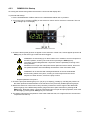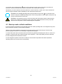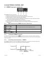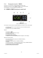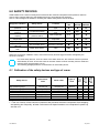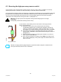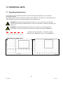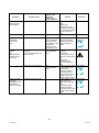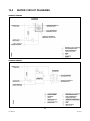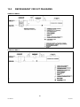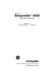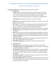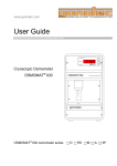
1
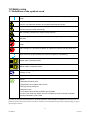
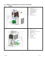
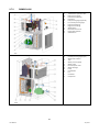
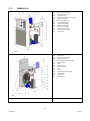
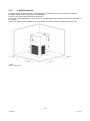
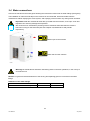
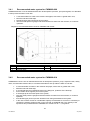
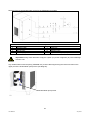
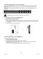
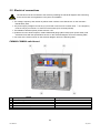
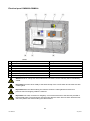
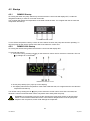
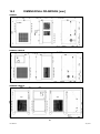
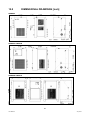
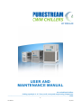
USER AND MAINTENANCE MANUAL Air cooled liquid chillers Cooling capacity 0.4 - 3.7 Tons, scroll, rotary and reciprocating compressors ............................................................................................................................................ 60Hz 1 User Manual July 2013 Dear Customer, Thank you for the trust you have placed in us. Please read this manual carefully to obtain the best performance from our product. In order to avoid incorrect operating conditions and danger for the operators, it is essential that you follow the directions meticulously as well as the current accident-prevention laws in the country of use. Each CWM chiller is rigorously tested before being packed. This verifies that there are no manufacturing defects and that the machine performs correctly the functions for which it was designed. This manual must be kept for future reference and is an integral part of the chiller you have purchased. Due to continuous technical development, we reserve the right to make the necessary modifications without any obligation to give advance notice. Do not hesitate to contact us if you have any problems or need more information. The product identification plate, located on the side of the chiller, contains all essential information about the machine. During installation, fill in the table below, copying the data on the identification plate. You will have to give this data to the manufacturer, or reseller, whenever you request information, replacement parts, etc., during the warranty period. Removing or tampering with the identification plate will void the warranty. Example Fill in this identification plate Warranty conditions: For 12 months from the commissioning date, and no more than 14 months from the shipping date, any parts that were originally defective will be repaired or replaced at no charge. Expenses for transport and travel, room and board for our technicians are excluded. The warranty excludes any liability for direct or indirect damage to persons, animals and/or property that are caused by incorrect use or inadequate maintenance and is exclusively limited to manufacturing defects. The right to service under the warranty is secondary to your faultless observance of the installation, use and maintenance instructions in this manual. The warranty will be voided immediately if the chiller is modified or tampered with, even slightly. When requesting warranty service, you must provide the data on the product's identification plate. 2 User Manual July 2013 Summary 1.0 Safety rules .................................................................................................................................................. 5 1.1 Definitions of the symbols used .............................................................................................................. 5 1.2 Warnings ............................................................................................................................................ 6 1.3 Proper use of the chiller .................................................................................................................... 6 1.4 Instructions for using equipment under pressure conforming to PED Directive 97/23/EC .............. 6 2.0 OPERATION AND MAIN COMPONENTS ................................................................................................. 7 2.1 Chilling circuit .......................................................................................................................................... 7 2.2 Water circuit ...................................................................................................................................... 8 2.3 Fan ..................................................................................................................................................... 8 2.4 Condensation control .............................................................................................................................. 8 2.5 Control of the water temperature..................................................................................................... 8 2.6 Protecting the integrity of the machine ............................................................................................ 8 2.7 CWM units: identification of the main components ......................................................................... 9 2.7.1 CWM002 ................................................................................................................................... 9 2.7.2 CWM003÷006 ......................................................................................................................... 10 2.7.3 CWM008÷014 ......................................................................................................................... 11 3.0 INSTALLATION...................................................................................................................................... 12 3.1 Transport ............................................................................................................................................... 12 3.2 Storage............................................................................................................................................. 12 3.3 Place of installation ......................................................................................................................... 12 3.3.1 Installation spaces .................................................................................................................. 13 3.4 Water connections .......................................................................................................................... 14 3.4.1 Recommended water system for CWM002÷006 ................................................................... 15 3.4.2 Recommended water system for CWM008÷014 ................................................................... 15 3.4.3 Use of ethylene glycol as a winter anti-freeze ........................................................................ 17 3.4.4 Charging the water circuit CWM002-006 ................................................................................ 17 3.4.3 Charging the water circuit CWM008-014 ................................................................................ 17 3.5 Electrical connections ...................................................................................................................... 18 3.5.1 Connecting a remote on/off switch......................................................................................... 20 3.5.2 Connection of a remote alert warning indicator ..................................................................... 20 4.0 PRELIMINARY CHECKS AND START-UP ................................................................................................ 20 4.1 Preliminary checks and preparation for the first start-up............................................................... 20 4.2 Startup ............................................................................................................................................. 21 4.2.1 CWM002 Startup .................................................................................................................... 21 4.2.2 CWM003-006 Startup ............................................................................................................. 21 4.2.3 CWM008-014 Startup ............................................................................................................. 22 4.3 Start-up under critical conditions .................................................................................................... 23 5.0 ELECTRONIC CONTROL UNIT ............................................................................................................... 24 5.1 CWM002 electronic control unit ..................................................................................................... 24 5.1.1 Main functions of the CWM002 electronic control keys ........................................................ 24 5.1.2 Turning the CWM002 on and off ............................................................................................ 24 5.1.3 Controlling water temperature – CWM002 ........................................................................... 24 5.1.4 Changing the set point – CMW002 ......................................................................................... 25 5.2 CWM003-CWM014 electronic control unit ..................................................................................... 25 5.2.1 Main functions of the electronic controller buttons and meanings of the icons - CWM003CWM014 26 5.2.2 Turning on and off CWM003-CWM014 .................................................................................. 27 5.2.3 Controlling water temperature – CWM003-CWM014 ........................................................... 27 5.2.4 Changing the set point - CWM003÷CWM014 ....................................................................... 28 5.2.5 Changing the type of restart after a power failure - CWM003-CWM014 .............................. 28 5.2.6 Changing the serial address (MODBUS and CAN) - CWM003-CWM014 ................................ 28 3 User Manual July 2013 5.2.7 Display of inputs and outputs - CWM003-CWM014 ............................................................. 29 5.2.8 Displaying the software release version of the electronic controller CWM003-CWM014 .... 29 5.2.9 Displaying the parameter set version - CWM003-CWM014 .................................................. 29 5.2.10 Alarms - CWM003÷CWM014................................................................................................... 30 5.2.11 Displaying and resetting alarms - CWM003-CWM014 ............................................................ 30 5.2.12 Table of alarm codes - CWM003÷CWM014 ............................................................................ 30 6.0 SAFETY DEVICES ................................................................................................................................... 31 6.1 Calibration of the safety devices and type of rearm ....................................................................... 31 6.2 Rearming the high-pressure pressure switch .................................................................................. 32 7.0 OPERATING LIMITS .............................................................................................................................. 33 7.1 Operating temperatures.................................................................................................................. 33 7.3 Low water temperatures ................................................................................................................. 36 7.3.1 Changing the setting of the anti-freeze thermostat – CWM003-CWM014 ........................... 36 7.3.2 Recommended glycol percentages for operating with low water temperatures. ................. 36 8.0 MAINTENANCE AND INSPECTIONS AND PERIODIC CHECKS ................................................................ 37 9.0 TROUBLESHOOTING ............................................................................................................................ 38 10.0 DISMANTLING THE CHILLER................................................................................................................ 43 12.0 WATER CIRCUIT DIAGRAMS ................................................................................................................ 44 13.0 REFRIGERANT CIRCUIT DIAGRAMS ...................................................................................................... 45 14.0 DIMENSIONAL DRAWINGS [mm] ........................................................................................................ 46 15.0 DIMENSIONAL DRAWINGS [inch] ....................................................................................................... 47 4 User Manual July 2013 1.0 Safety rules 1.1 Definitions of the symbols used Read this use and maintenance manual carefully before performing any repairs on the chiller. Warnings of a general character; risk of danger or possibility of damaging the machine, pay particular attention to the phrase following this symbol. Risk of electrical danger; the phrase highlights conditions that could be fatal. Follow the instructions provided meticulously. Risk of danger; component or system under pressure. Risk of danger; component or system that can reach high temperatures during operation. Risk of danger; it is absolutely forbidden to use water to extinguish fires near or on the chiller. Risk of danger; it is absolutely forbidden to operate the machine with the panel open. Service that can be performed by the machine’s operator, if qualified (1). Water input connection point. Water output connection point. Dispose of each type of material in accordance with the requirements of the country of use. NOTE: Phrases to be emphasized that do not contain safety rules. This chiller has been carefully designed and constructed to be environmentally friendly: Refrigerants without CFC. Expanded foam insulation without CFC. Energy-saving techniques. Reduced noise. The chiller and its packing materials are recyclable. In order not to hinder our efforts, the user is required to obey the simple ecological warnings indicated by this symbol. (1) These are persons with the experience, technical preparation and knowledge of standards and regulations who are qualified to perform the necessary actions and able to recognise and avoid possible dangers while handling, installing, using and maintaining the machine. 5 User Manual July 2013 1.2 Warnings Only qualified persons may use and maintain electrically-powered equipment. Before commencing maintenance operations ensure no parts of the machine are live and it cannot be re-connected to the electrical power supply. The CWM chillers contain R134a (CWM002) and R407C (CWM003-014) refrigerant. Operations on the cooling circuit must only be performed by specialist personnel with suitable equipment. Any modifications to the machine or related operating parameters not previously verified and authorised by the Manufacturer may be hazardous and will invalidate the guarantee. Do not use water to extinguish fires near or on the chiller. 1.3 Proper use of the chiller CWM units are monobloc water chillers with air-condensation. They are intended for use in industrial process or air-conditioning systems requiring chilled water. Any other use is considered as incorrect. The manufacturer is not liable for damage resulting from inappropriate use; in all cases, the user is liable for any resulting hazards. Proper use requires conforming to the installation conditions and limits of operation (see sections 3.5 and 7.0); in particular: • • • • power voltage and frequency; pressure, temperature of incoming water; water flow rate; surrounding temperature. The chiller has been tested and completely assembled. The user must only make the connections to other systems, as described in the chapters that follow. 1.4 Instructions for using equipment under pressure conforming to PED Directive 97/23/EC The proper use of equipment under pressure is an essential prerequisite for ensuring safety. To this end, the user must proceed as follows: 1. Use the equipment properly within the temperature limits shown in the operating limits stated on the manufacturer’s name/data plate. 2. Do not solder on the exchangers or refrigerant fluid pipes. 3. Do not install the equipment in insufficiently ventilated rooms, areas exposed to sources of heat or near inflammable substances. 4. During operation, the equipment must not be subjected to vibrations that could cause fatigue failures. 5. Keep the documentation attached to the equipment (user manual, declaration of conformity, etc.) for future reference. 6. The maximum working pressure stated on the manufacturer’s data plate must not be exceeded. Prior to use, the user must fit safety / pressure relief devices. 6 User Manual July 2013 2.0 OPERATION AND MAIN COMPONENTS 2.1 Chilling circuit CWM chillers use a vapour-compression cycle in a chilling circuit that essentially consists of the following components: evaporator, compressor, condenser, lamination device (thermostatic expansion valve or capillary tube). Evaporator: heat exchanger (co-axial or braze-welded) to enable heat exchange between the water and the coolant liquid without them coming into contact with each other. The water is cooled when it passes through the evaporator. Compressor: compresses the steam from the evaporator to send it to the condenser at a higher pressure. Condenser: finned pipe exchanger to enable heat exchange between the coolant and the air; it creates coolant gas condensation (which flows inside the pipes) transferring the gas coolant condensation heat to the air (which flows externally); high pressure coolant liquid is thus produced. Lamination device: reduces the pressure of the liquid coolant coming from the condenser, which is then sent to the evaporator. In particular, the thermostatic valve can modulate coolant flow such as to maintain continuous heating of the gas exiting the evaporator, during various operating conditions and therefore guaranteeing gas flow without liquid parts inside the compressor. Thanks to these components, the vapour-compression cycle works as follows: the refrigerant liquid evaporates in the evaporator, chilling the water; the refrigerant vapours are then aspirated from the compressor, which compresses them and sends them to the condenser under high pressure; here, thanks to a flow of forced air from the fans, the high-pressure refrigerant gas is cooled, making it condensed and undercooled. The flow of refrigerant liquid then passes through the lamination valve (thermostatic expansion valve), which drastically reduces its pressure: the refrigerant liquid returns to the evaporator at a reduced pressure where it again evaporates, taking heat from the water. The chilling circuit also includes a water pump, which ensures the flow of water to be chilled by evaporation, and the fan which ensures the condenser is cooled. 7 User Manual July 2013 2.2 Water circuit The water circuit mainly consists of a pump, evaporator, tank, bypass calibrated between the pump discharge and the system backflow, pressure gauge on the pump discharge, and level sensor (optional). The water flows into the evaporator first where it is cooled, then into the tank, and is then suctioned by the pump which sends it to the system (see water diagrams section 12.0) CWM002-006 models have an open circuit with a tank at atmospheric pressure. CWM008-014 models have a closed circuit with a pressurised tank; these models are also equipped with a differential pressure gauge to protect the evaporator, automatic air bleeder valve, safety valve and expansion tank. Units can be equipped with pumps with an oversized delivery head (P5). 2.3 Fan The fan forces air through the condenser fins to remove the coolant gas condensation heat, therefore limiting the pressure inside the condenser. CWM chillers are equipped with axial fans and have internal heat protection for the motor windings (excluding model CWM002). 2.4 Condensation control When the ambient air temperature decreases, air flow cooling capacity increases slightly, causing a reduction in pressure inside the condenser; to limit this decrease in condensation pressure from falling below acceptable limits for good cooling circuit operation the fan stops temporarily. 2.5 Control of the water temperature The purpose of the chiller is to maintain the temperature of the water produced within a desired interval as the load on the system varies; this is handled by an electronic controller and a temperature probe that turn the compressors on and off appropriately (see also sections 5.1.3 and 5.2.3) 2.6 Protecting the integrity of the machine In addition to controlling the temperature, the electronic controller uses pressure gauges, thermostats and timers to prevent and handle situations that could compromise the integrity of the machine (also see Chapter 6.0, Safety Devices). 8 User Manual July 2013 2.7 CWM units: identification of the main components 2.7.1 CWM002 21 14 08 07 16 09 06 32 15 19 18 Filling inlet Level sensor (optional) Evaporator Fan control pressure gauge Power supply cable Low pressure fitting High pressure fitting High pressure fitting Water bypass Switch Electronic control unit 22 10 17 23 05 24 03 13 12 04 11 01 09 Water inlet Tank Water level indicator Water outlet Coolant pressure gauges (optional) Water discharge Pump Water pressure gauge Fan Coolant filter Condenser Compressor Low pressure fitting 9 User Manual July 2013 2.7.2 CWM003÷006 21 02 06 14 08 20 07 09 32 15 18 19 25 Filling inlet Thermostatic expansion valve High pressure gauge Level sensor (optional) Evaporator Low pressure gauge (optional) Fan control pressure gauge Low pressure fitting High pressure fitting Water bypass Electronic control unit Disconnecting switch Switchboard 22 05 17 10 13 23 16 24 03 04 12 11 01 Water inlet Coolant pressure gauges (opt) Water level indicator Tank Water pressure gauge Water outlet Electrical power inlet Water discharge Pump Coolant filter Fan Condenser Compressor 10 User Manual July 2013 2.7.3 CWM008÷014 19 18 29 30 28 31 16 20 09 06 27 32 14 01 Disconnecting switch Electronic control unit On/Off remote switch Expansion tank Differential water pressure gauge Water safety valve Electrical power inlet Low pressure gauge Low pressure fitting High pressure gauge Pressure transducer High pressure fitting Level sensor (optional) Compressor 05 22 13 08 02 15 10 23 24 12 03 26 04 11 25 Coolant pressure gauges Water inlet Water pressure gauge Plate evaporator Thermostatic expansion valve Water bypass Tank Water output Water discharge Fan Pump Coolant glass warning light Coolant filter Condenser Switchboard 11 User Manual July 2013 3.0 INSTALLATION 3.1 Transport The units are supplied packed in a cardboard box on a wooden pallet. After checking that the packing is undamaged, position the unit near the installation site and unpack it. Always keep the chiller vertical: turning it upside down can irreparably damage several parts of the unit. Handle with care. Violent falls can cause irreparable damage. The centre of the machine is approximately its centre of gravity. In any case, when handling the machine with a forklift truck or pallet jack, always check its stability before lifting. 3.2 Storage Protect the machine from bad weather, even if packed. Always keep the chiller vertical, even when in storage. Turning it upside down can irreparably damage several parts of the unit. If not used, the chiller can be stored packed in an enclosed place, free of dust, with a maximum temperature of 50 °C // 122°F and specific humidity of no higher than 90%. The packing material is recyclable. Dispose of each type of material in accordance with the requirements in the country of use. 3.3 Place of installation Warning! The CWM002 model is intended for indoor installation only. All other CWM units can be installed indoors or outdoors. To determine the best place to install the unit, it is important to consider the following aspects: • the dimensions and source of the water pipes; • the location of the electricity; • the solidity of the support surface; • avoid any obstacles to the flow of the fan which could cause the recirculation of air to the condenser. • avoid the possible reflection of sound waves: (do not install in narrow or tight spaces). • provide access for maintenance or repair (see paragraph 3.3.1, “Installation spaces”). • Average air temperature in the chosen installation area (see Section 7.0 Operating limits) Attention: if the machine is installed outside, it could find itself at a temperature lower than 0°C//32°F, when stopped; the formation of ice could damage the evaporator. If you do not intend to drain the machine during the winter, you must add anti-freeze to the water circuit (see paragraph 3.4.2, Use of ethylene glycol as a winter anti-freeze) 12 User Manual July 2013 3.3.1 Installation spaces To ensure the good functioning of the unit and access for maintenance, you must respect the minimum installation space shown in the figure in this paragraph. The exit of air from the fans must not be obstructed. In any case, avoid all situations in which hot air can circulate between the output of the fans and the intake of the machine. Contact our office to verify feasibility in all cases where one of the preceding conditions cannot be met. 0,8 m = 31,5 inches 13 User Manual July 2013 3.4 Water connections Connect the machine to the water pipes following the instructions located near its water fittings (see figures) The installation of outlet and inlet taps on the machine is recommended, which will enable machine maintenance without emptying the entire system, and emptying of the machine only during winter downtime. Important! Install the mechanical water filter, provided with the machine, on its input: scum and impurities can seriously damage the evaporator. We recommend an extraordinary cleaning of the mechanical water filter after the machine has been running for the first week (also see Chapter 8.0, Maintenance and periodic inspections). . Water input to the machine Water exit from the machine Warning! No naked flames should be used during water connection operations, in the vicinity of or inside the unit. NOTE It is a good rule that the diameters of the arriving and departing pipes be not less than the water fittings. Diameters of the water fittings. CWM models Diameter of the in/out water fittings 002÷006 1/2” FM 008÷014 1” FM 14 User Manual July 2013 3.4.1 Recommended water system for CWM002÷006 CWM002-006 units come as standard with a tank at atmospheric pressure, pump and bypass; it is advisable to also provide the water circuit with: • • • • A mechanical filter for water in the machine inlet pipes, with mesh no greater than 1mm; Machine inlet and outlet taps; Discharge tap at the lowest point of the system; Inlet and outlet pressure gauges and thermometers for water from the machine, to control its operation. Diagram of recommended water circuit for CWM002-006 models Key 1 2 3 Tap Mechanical filter Pressure gauge 3.4.2 4 5 Thermometer System/unit discharge Recommended water system for CWM008÷014 CWM008-0014 units come as standard with a tank at atmospheric pressure, pump, expansion tank, safety valve, and automatic bleeder valve; it is however advisable to also provide the water circuit with: • • • • • • • • A mechanical filter for water in the machine inlet pipes, with mesh no greater than 1mm; Machine inlet and outlet taps; a mechanical filter and a backflow valve on the filling line, upstream of the feed tap; an air bleeder at the highest point of the system; a discharge tap at the lowest point of the system; Inlet and outlet pressure gauges and thermometers for water from the machine, to control its operation; anti-vibration pipe joints to prevent vibrations from being transmitted to the system. In the case of water circuits of considerable capacity it is advisable to check if it is necessary to combine the existing expansion tank on the unit with an additional tank. The capacity of the 3 expansion tank provided with the CWM008-014 models is 5 dm // 1,32 gallons . 15 User Manual July 2013 Diagram of the recommended water circuit for the CWM008-014 models Key 1 2 3 4 5 Tap Mechanical filter Anti-vibration joints Bleeder valve Pressure gauge 6 7 8 10 11 Thermometer Discharge Filling unit Backflow valve Expansion tank (if required) Important! During winter downtime empty the system (or just the refrigerator) to prevent damage from the cold. Any residual water inside the pump (CWM008-014) must be discharged using the relevant screws on the upper part of the archimedean pump screw (see diagram). Archimedean pump screw 16 User Manual July 2013 3.4.3 Use of ethylene glycol as a winter anti-freeze Instead of emptying the system in the winter, you can charge the system with a mixture of water and a suitable percentage of ethylene glycol, chosen as a function of the lowest expected temperature of the outside air. Percentages of ethylene glycol recommended as a function of the expected temperature of the outside air. Outside air temperature [°C] Outside air temperature [°F] Percentage of ethylene glycol [%] 0 32 10 -5 23 15 -10 14 20 -12 10,2 25 -15 5 30 Attention: Maximum concentration of ethylene glycol allowed: 30%. 3.4.4 Charging the water circuit CWM002-006 • Check that the drain taps are turned off. • Open the system interception devices. • Feed the water from the filling inlet above the machine until the water reaches the required level (near the transparent level indicator – see diagram). When the pump starts check the level again and top up if necessary. • Check for any leaks by examining the circuit. 3.4.3 Charging the water circuit CWM008-014 Check that the drain taps are turned off. • Open all the system’s bleed valves. • Turn on the system's shut-off devices. • Start filling by slowly turning on the system's water-charging tap. • When water starts coming out of the bleed valves, close them and continue charging until the manometer shows at least 1 bar // 15 psi. • Check for any leaks by looking at the manometer and inspecting the circuit. 17 User Manual July 2013 3.5 Electrical connections The machine must be connected to the electricity following the electrical diagram and conforming to the current laws and regulations in the place of installation. • The voltage, frequency and number of phases must conform to the data shown on the machine's identification plate. • The power supply voltage must not vary by more than ±10% from its nominal value. The frequency must not vary by more than ±1% from its nominal value (±2% for brief periods). • The imbalance between power phases must be <2%. • Upstream from the electrical panel, install a differential gauge (IDn=0.03A) (main power switch) and slow-blow fuses with the specifications shown on the electrical diagram and in the following table. • Use wires of the section shown on the electrical diagram and in the following table. CWM003-CWM006 switchboard: N° 1 2 3 4 5 Description Disconnecting switch Relay switch Transformer Condenser of the compressor Terminal boards Component ID QS KHP, KCC, KCP TF CR A1,A2 18 User Manual July 2013 Electrical panel CWM008÷CWM014: N° 1 2 3 4 5 6 7 8 Description Cut-off switch Compressor and pump protections Fuses Relays Transformer Phase-sequence control relay Compressor and pump remote switches Terminal strip Component ID QS QC1 QP1 FU1,FU2 etc. KHP, KON, KGA TF RPP KC1. KP1 A1, A2 Attention! Never change the internal electrical connections, as the warranty will be immediately voided. Important! Screw the wires solidly to the terminal strip of the cut-off switch and lock the wire with a cable-gland. Important! Make the cable entering the machine enters the cable-gland from below: this prevents rain from dripping inside the machine. Important! The earth connection is obligatory: connect the earth wire to the terminal provided in the electrical panel. The ground wire must be longer than the other wires so that it will be the last one to be pulled if the device holding the cable loosens. 19 User Manual July 2013 3.5.1 Connecting a remote on/off switch A remote ON/OFF switch can be installed using the terminal clamps on the switchboard terminal board, as shown in the following table: Models Terminals Voltage CWM002 Not available Not available CWM003-006 X2.7 – X2.8 24 V CWM008-014 X2.11 - X2.12 24 V Consult the electrical diagram NB: for CWM008-014 models any remote switch installed will be activated by putting the I/O/REM switch on the switchboard cabinet door in the REM position. 3.5.2 Connection of a remote alert warning indicator A remote alert warning indicator can be installed using the terminal clamps in the switchboard cabinet, as shown in the following table: Models Terminals Voltage CWM002 Not available Not available CWM003-006 X2.9 – X2.10 24 V CWM008-014 X2.14 – X2.15 – X2.16 No Voltage Consult the electrical diagram 4.0 PRELIMINARY CHECKS AND START-UP 4.1 Preliminary checks and preparation for the first start-up Before starting up the unit, it is a good idea to do the following: 1. Check that the water shut-off valves are open. 2. Verify the regular water level in the tank (for open water systems – CWM002-006) 3. Check the pressure shown on the gauge with the pumps stopped is approximately 1 bar (for closed water systems - CWM008-014). 4. Check that the surrounding temperature is in the range for the machine to function (see Chapter 7.0, Operating Limits). 5. Check the disconnecting switch on the machine switchboard is open. 6. Check that the run/stop switch (I/O/REM) in the electrical panel is in the 0 position (only for CWM008÷014 models) 7. Check that the mains voltage matches the voltage on the machine's identification plate with a tolerance of ±10%. 8. Close the main power supply switch. 9. Close the cut-off switch on the machine's electrical panel. 20 User Manual July 2013 4.2 Startup 4.2.1 CWM002 Startup On closing the switch the pump will start up and the electronic control unit will display OFF; to start the refrigerator hold key 4 down for more than 5 seconds. The controller will display the temperature of the water inside the tank - if it is higher than the set value the compressor will start up. CWM002 electronic control To turn off the compressor hold key 4 down for more than 5 seconds; the pump will continue operating. To stop the pump as well use the switch at the side of the electronic control unit. 4.2.2 CWM003-006 Startup On closing the disconnecting switch the electronic control unit will display OFF. To proceed with startup: 1. Turn on the unit by pressing UP (3) on the electronic control unit for more than 5 seconds. The icon (7) will light up on the display. CWM003÷014 electronic control 2. Check pump startup (icon (10) lit up on the display) 3. The display will show the temperature of the water inside the tank; if it is higher than the set value the compressor will start up. Turn off the unit by holding the UP (3) key on the electronic control unit for more than 5 seconds; the electronic control unit will first switch off the compressor then shortly after the pump. WARNING: it is important not to turn off the unit using the main power switch or disconnecting switch on the machine switchboard as this could cause a delayed switch-off of the pump with respect to the compressor, which could damage the evaporator. 21 User Manual July 2013 4.2.3 CWM008-014 Startup On closing the disconnecting switch the electronic control unit will display OFF. To proceed with startup: 1. Put the On/Off/Remote 1/0/Rem switch on the switchboard cabinet door in position 1. 2. Turn on the unit by pressing UP (3) on the electronic control unit for more than 5 seconds. The icon (7) will light up on the display. CWM003-014 electronic control unit 3. Check the alert symbol (8) does not appear on the electronic control unit; if it does appear press the X ESC(2) key to see which type of alert has been flagged. WARNING: on first starting up an alert could occur in relation to an error sequence in the R/S/T phases, shown by the code AC0 on pressing the X ESC(2) key. This safety system safeguards the compressor from the possibility of turning in the wrong direction. Should this occur open the main power switch upstream of the machine, and invert two phases between them immediately downstream of the main switch itself. WARNING: do not interfere with cabling downstream of the unit switchboard disconnecting switch at any time, as doing so could compromise the correct sequence of other devices, such as the pump or fans. Repeat operations from point 1. 4. Check the pump has started (pump icon (10) lit up on display), possibly by checking the pressure of the water upstream and downstream of the machine on the previously installed pressure gauges. 5. Wait for the electronic control unit to verify continuity of water flow via the signal of the differential pressure gauge; if the differential pressure gauge intervenes (alert code A03 on pressing the X ESC(2) key), bleed the system, check the interception taps are open and pump operation, then reset the alert flag by pressing the X ESC(2) key for 5 seconds. 6. The display will show the temperature of the water inside the tank; if it is higher than the set value the compressor will start up. 22 User Manual July 2013 Turn off the unit by holding the UP (3) key on the electronic control unit for more than 5 seconds; the electronic control unit will first switch off the compressor then shortly after the pump. Alternatively, once the machine has been switched on via the electronic control unit it can be switched on and off using the ON/OFF switch (I/O/REM) on the switchboard cabinet door. WARNING: the 1/0/REM operating switch has precedence over the UP (3); by turning off the machine using the 1/0/REM operating switch it will not be possible to start it again using the UP (3) key on the electronic control unit. WARNING: it is important not to turn off the unit using the main power switch or disconnecting switch on the machine switchboard as this could cause a delayed switch-off of the pump with respect to the compressor, which could damage the evaporator. 4.3 Start-up under critical conditions If the air and water temperatures are especially high and outside operating limits, the refrigerator may have been required to operate in unfavourable conditions. Startup under critical conditions could result in the high pressure gauge intervening (to reset the high pressure gauge see Section 6.2: Resetting the high pressure gauge). To resolve this issue reduce the heat load of the machine by partially intercepting the users or, if this is not possible, by reducing the rate of water flowing in the evaporator - to this end partially close the outlet tap from the refrigerator and restart the machine. Let the refrigerator operate under these conditions until the water temperature falls within stipulated operating values, then the tap can be opened fully. 23 User Manual July 2013 5.0 ELECTRONIC CONTROL UNIT 5.1 CWM002 electronic control unit The CWM002 electronic control unit • Displays the temperature of the water exiting the refrigerator. • Enables the required temperature of the water produced to be set (set point). • Enables compressor activation and deactivation (standby). • Controls on/off compressor operation depending on the temperature of the water measured with the set point and upper differential (3°C // 3K //5,4°F). • Guarantees minimum compressor on/off times to maintain its integrity. • Signals any faults in the temperature probe with the code OR, simultaneously turning off the compressor. 5.1.1 N° 1. 2. 3. 4. Main functions of the CWM002 electronic control keys Key Setpoint key Down key Enables the increase of the set point value used along with key 1 Up key Exit/standby key 5.1.2 Functions Displays the set point value Enables setting of the set point used along with keys 2 and 3 Enables the decrease of the set point value used along with key 1 Activates/deactivates the compressor when held for more than 3 seconds. Turning the CWM002 on and off To enable compressor operation hold the 4 key down for more than 3 seconds; to disable it repeat the same action: the fan and pump operate independently from the electronic control unit and can be stopped via the main switch. 5.1.3 Controlling water temperature – CWM002 The CWM002’s electronic control unit regulates the temperature on the basis of a set point value and an upper differential of 3°C // 3K // 5,4°F, according to the following diagram: 24 User Manual July 2013 5.1.4 Changing the set point – CMW002 Press key 1 for at least half a second to display the setpoint value. Keeping key 1 pressed, use keys 2 and 3 to set the required value. On releasing key 1 the new setpoint value will be stored. 5.2 CWM003-CWM014 electronic control unit CWM003-CWM014 electronic control unit The electronic control unit has a 7-segment display and a series of icons, and manages: • compressor operation to ensure temperature control of the water produced • pump operation • fan speed control (only CWM008-CWM014) displays: • • • • • • unit status (icon )(7) compressor status (compressor icon) (9) fan status (fan icon) (11) pump status (pump icon) (10) temperature of water produced (5) all digital/analogue inputs/outputs (parameter navigation via the display) displays the following alerts: • • • • • • • • water differential pressure gauge (only CWM008-CWM014) high pressure gauge low pressure gauge (optional on CWM003-CWM006) antifreeze compressor protection – wrong R/S/T phase sequence (only CWM008-CWM014) pump and fan protection (only CWM008-CWM014) insufficient water level in tank (optional) pressure and temperature probe fault 25 User Manual July 2013 5.2.1 Main functions of the electronic controller buttons and meanings of the icons - CWM003-CWM014 N° Button/Icon Functions 1. ENTER 2. X ESC 3. UP 4. DOWN 5. DISPLAY 7. COOLING icon Accesses the menu. Goes to the next menu level. Goes to the mode for editing the selected parameter. Confirms value entered for a parameter. Accesses the list of active alarms. When navigating the menus, returns to the previous menu level (pressed once). When navigating the menus, returns to the main page (pressed several times). Exits from parameter edit mode without saving the changes made. When pressed for at least 5 seconds, turns the unit on and off. During menu navigation, scrolls up through the menu items. Increases the value of the parameter being modified. Scrolls up through the alarm list. During menu navigation, scrolls down through the menu items. Decreases the value of the parameter being modified. Scrolls down through the alarm list. During the machine’s operation, shows the temperature of the water exiting the evaporator. During navigation of the menu, indicates the directory above the one where you are. During changing of parameter, indicates the value to be changed, flashing Indicates that the machine is ON, even when the compressors are stopped. 8. ALARM icon Indicates the presence of one or more active alarms. 9. COMPRESSOR icon 10. PUMP icon 11. FAN icon They indicate the state of the compressor and, more precisely: Off: compressor OFF On: compressor ON Slow flashing: compressor about to turn on. Fast flashing: compressor about to turn off. Indicates the state of the pump, more precisely: Off: pump OFF On: pump ON Fast flashing: pump about to turn off. Indicates the state of the fans: On: fans ON Off: fans OFF. 26 User Manual July 2013 5.2.2 Turning on and off CWM003-CWM014 To turn the unit on, hold down the UP button (3) for more than five seconds To turn the unit off, hold down the UP button (3) for more than five seconds Optionally, once the machine has been turned on using the electronic controller, it can be turned on and off from the run/stop switch (I/O/REM) on the door of the electrical panel. Attention: the run/stop I/O/REM switch has precedence over the “UP” button (3): after turning the machine office from the run/stop I/O/REM switch, it will not be possible to restart it with the “UP” button (3) on the electronic controller. 5.2.3 Controlling water temperature – CWM003-CWM014 The machines have a temperature probe at the exit from the evaporator: based on this temperature, the electronic controller starts and stops the compressors to keep this temperature as close as possible to the temperature set point. The electronic controller regulates the exit temperature of the evaporator using a dead-zone system: this system is based on three temperature intervals: lower differential - dead zone - upper differential and two temperature values: the set point and anti-freeze. All these values are distributed on the temperature scale as shown in the figure: Dead zone: 1°C // 1,8°F Lower differential: 1°C // 1,8°F Below this value, the compressors are forced off to avoid the formation of ice. Set point Anti-Freeze Anti-Freeze Lower differential Set point In this interval, the compressors are progressively turned off as the temperature of the water decreases: Upper differential: 1°C // 1,8°F Water temp. exiting the evaporator [°C] //[°F] Dead zone Upper differential In this interval, the compressors that are on are kept on and those that are off are kept off. In this interval, the compressors are progressively turned on as the temperature of the water increases: All the compressors are on. Numeric examples: 3°C // 37,4°F 3°C // 37,4°F From 6°C//42,8°F to 7°C//44,6°F From 9°C//48,2°F to 10°C//50°F 7°C 44,6°F 10°C 50°F From 7°C//44,6°F to 8°C//46,4°F From 8°C//46,4°F to 9°C//48,2°F Above 9°C//48,2°F From 10°C//50°F to 11°C//51,8 From 11°C//51,8°F to 12°C//53,6°F Above 12°C//53,6°F The set point of the water can be changed: the other parameters (differentials and dead zone) remain constant and follow the set-point value, moving on the temperature scale (see the numeric examples in the table above). 27 User Manual July 2013 5.2.4 Changing the set point - CWM003÷CWM014 WARNING: if it was not specified during the proposal phase that the unit is required to produce water at temperatures near to 0°C //32°F or below contact the company. (See section 7.3 Low water temperatures). To change the set point of the exiting water, proceed as follows: from the main screen, press ENTER use the DOWN button to go to the PAR menu. Press ENTER , and use the DOWN button to go to the REG menu. Press ENTER In the REG SET menu, press ENTER and the set point will be displayed. To change it, press ENTER and the value will flash. Use the UP and DOWN ,buttons to set the desired value. To confirm it, press ENTER . To exit without saving it, press X ESC. Press X ESC again until you return to the main screen. 5.2.5 Changing the type of restart after a power failure - CWM003-CWM014 In the case of a power failure, the chiller can behave in three different ways when power is restored: • stay off, • start, • return to the same condition it was in when the power failed. To select one of these options, proceed as follows: From the main screen, press ENTER Use the DOWN to go to the PAR menu. Press ENTER . Go to the GEN menu. Press ENTER Go to dSP menu. Use the DOWN to go to the STU menu, press ENTER . In the Y02 menu, the type of restart currently set will be displayed, which can be one of the following: • EQUA: when the power returns, the machine will work in the same way as before the power failed. • ON: when the power returns, the machine will start. • OFF: when the power returns, the machine will stay off. To change the type of restart, press ENTER and the parameter begins to flash. Use the UP and DOWN buttons to select the desired parameter and confirms with ENTER . To return to the main screen, press X ESC four times. 5.2.6 Changing the serial address (MODBUS and CAN) - CWM003-CWM014 If you are installing a serial network with several devices, it may be necessary to change the serial address of the electronic controller, which is set to 1 at the factory. From main screen, press ENTER . Using the DOWNbutton, go the PAR menu. Press ENTER . In the PAR GEN menu, press ENTER . Use the DOWN arrow to scroll to the GEN SER menu and press ENTER : the current serial address is displayed. From the SER menu, press ENTER : the current value will flash. Use the UP and DOWN arrows to set the desired value. To return to the main screen, press X ESC four times. 28 User Manual July 2013 5.2.7 Display of inputs and outputs - CWM003-CWM014 It is possible to display the analogue and digital outputs to check the operation of the machine and its main components. From the main screen, press ENTER . Use the DOWN button to move to the I/O menu. From here, press ENTER to access the I/O Od menu. Press ENTER and, using the UP and DOWN buttons, you can display all the values of the analogue and digital inputs and outputs. Press X ESC again until you return to the main screen. The following values can be displayed: Input/Output CWM 003÷006 CWM 008÷014 Description Unit of measure/Key AI 1 - analogue input AI 2 - analogue input Temperature at the entrance of the machine Temperature at the exit of the machine °C °C AI 4 - analogue input n.u. Pressure of condenser Bar g AO 1 - analogue output1 n.u. Opt. Fan speed 0÷100% DI 1 - digital input 1 n.u. Chiller on/off from run/stop switch (I/O/REM) 0=on 1=off DI 2 - digital input 2 High-pressure pressure gauge DI 3 - digital input 3 Opt. Low-pressure pressure switch circuit DI 4 - digital input 4 Opt. Water differential pressure gauge (CWM008÷014) Water level protection (CWM003÷014 – opz.) 0=ok; 1=device intervention DI 5 digital input 5 n.u. Compressor and/or phase sequence protection 0=ok; 1=protection intervention DI 6 - digital input 6 n.u. Water level and/or pump and/or fan protection DO 1 - digital output 1 Alarm present DO 2 - digital output 2 Compressor DO 5 - digital output 5 Pump DO 6 - digital output 6 n.u. Fan 0=ok; 1=pressure gauge 0=ok; 1=pressure gauge 0=ok; 1=protection intervention 0=no alarm 1=alarm 0=off; 1=on 0=off; 1=on 0=off; 1=on Key: n.u. = not used - Opt = optional 5.2.8 Displaying the software release version of the electronic controller CWM003-CWM014 From the main screen, press ENTER . Use the DOWNbutton to go to the SER menu. Press ENTER . From the SER INF menu, press ENTER and here you can display the version of the software release installed in your controller. Press X ESC again until you return to the main screen. 5.2.9 Displaying the parameter set version - CWM003-CWM014 From the main menu press Enter , using the Down key go to menu PAr, press ENTER , in the GEN menu press ENTER , dSP is displayed, press ENTER , PAR is displayed, press ENTER , the number indicating the parameter set version is displayed. To exit press X ESC to return to the main menu. 29 User Manual July 2013 5.2.10 Alarms - CWM003÷CWM014 An alarm condition is signalled by the Alarm icon (8). Some alarms must be rearmed manually while for others, the rearm is automatic or semi-automatic. - Manual rearm: these alarms must be reset, which can only be done when the alarm condition no longer exists; only then can the machine resume operation. - Automatic rearm: the alarm is automatically deactivated as soon as the alarm condition ceases and the machine restarts by itself. However, the signal (Alarm icon (8)) remains on the display until the alarm code is displayed. - Semi-automatic rearm: semi-automatic alarms behave like automatic alarms; but if the same semiautomatic alarm occurs 5 times in 90 minutes, that alarm becomes a manual alarm; therefore to restart the machine, you will have to remove the cause of the alarm and reset it. - 5.2.11 Displaying and resetting alarms - CWM003-CWM014 The Alarm icon (8) turns on to indicate an alarm. To display the code of the alarm that intervened, press the X ESC button; use the UP and DOWN buttons to display the codes of any other alarms that intervened at the same time. To reset an alarm, the condition that caused it must no longer exist For example, if the low-pressure gauge has intervened, the alarm can only be reset when the pressure has risen beyond the reset value (see paragraph 6.1, Calibrating security devices and type of rearm). Then, after displaying the alarm, wait for normal conditions to be restored, press X ESC again, hold it down for 5 seconds and the alarm will be reset. 5.2.12 Table of alarm codes - CWM003÷CWM014 Alarm code CWM CWM 003÷006 008÷014 A03 A03 AP1 AH0 AL0 AH0 AL0 AC0 A7A A7b A7A A7b A7G A09 AE1 A09 AE1 Alarm description Type of reset Evaporator differential pressure switch Water level insufficient Pump magnetothermic circuit breaker, water level insufficient and/or ventilator thermal protection High refrigerant pressure Low refrigerant pressure Magnetothermic compressor circuit breaker and/or wrong phase sequence Entering water temperature probe failure Exiting water temperature probe failure Refrigerant pressure transducer failure High exiting water temperature warning Anti-freeze alarm Semiautomatic Semiautomatic Manual Manual Automatic Manual Automatic Automatic Automatic Automatic Automatic 30 User Manual July 2013 6.0 SAFETY DEVICES CWM chillers have a series of safety devices that limit the machine's temperature and pressure values to ensure that it operates within the anticipated limits and to avoid dangerous situations. Here is a list of dangerous situations, including the relative safety device and its location. Dangerous situation High condensation pressure Low evaporation pressure Low water flowcapacity Low water temperature High water pressure Frequent compressor start-ups Low water level in the tank CWM 002 CWM 003÷006 CWM 008÷014 n.a. Opt. Plate evaporator n.a. n.a. n.a. Safety valve Water exit from the evaporator Accumulation tank n.a. n.a. Anti-circulation timer Electronic controller Water-level sensor Tank Opt. Opt. Opt. Safety device High-pressure switch Low-pressure switch Location Compressor output pipe Compressor intake pipe Water differential pressure switch Anti-freeze thermostat Key: n.a. = not available - Opt = optional When they reach their calibration value, most of the security devices trigger an alarm managed by the electronic controller. For some safety devices, once the cause of the alarm times out, the machine resumes operation automatically as soon as the reset value is reached. Others must be manually reset to restart the machine (also see paragraph 5.2.10). The following paragraph lists the characteristics of each safety device. Reset value 30 (20*) barg 435 (290) psi 1,7 barg // 25 psi 18 mbar // 0,25 psi 3°C // 37,4°F 6 barg // 87 psi -5 min. 23 (14*) barg 333 (203) psi 2,7 barg // 39 psi 25 mbar // 0,36 psi 6°C // 42,8°F ---- Type of reset CWM 008÷014 High-pressure gauge Intervention value CWM 003÷006 Safety device CWM 002 6.1 Calibration of the safety devices and type of rearm Manual Automatic n.a. Opt Low-pressure gauge Semiautom n.a. n.a. Water differential pressure gauge Automatic n.a. Anti-freeze thermostat -n.a. n.a. Water safety valve Opt Semiautom Opt Water-level sensor (Opt.) -Anti-circulation timer** • * CWM002 values • **This is a function of the electronic controller that prevents the same compressor from stopping Opt and starting too frequently: at least 3 minutes must elapse between one compressor’s power up and the next. 31 User Manual July 2013 6.2 Rearming the high-pressure pressure switch The intervention of the high-pressure pressure switch is the only case in which, in addition to manually rearming the electronic controller, it is also necessary to reset the pressure switch itself. The high-pressure pressure switch is located in the compressor compartment on the uninsulated copper pipe that goes from the compressors to the condensation batteries; there is a manual-reset button on top of it. This can only be rearmed when the pressure in the circuit has fallen below the reset value (see table, “Calibration of the safety devices and type of rearm” in paragraph 6.1). Warning! The upper part of the compressor casing and discharge pipe are at a high temperature. Be especially careful when working in their vicinity. For this reason, when dealing with an intervention of the high-pressure switch, it is necessary to: A) identify the cause of the rise in pressure (fans not working, condensation batteries dirty or obstructed, obstacles to the flow of exiting air, operating temperature outside operating limits, etc. (also see Chapter 9.0, Trouble shooting) and remove the cause, if possible; B) wait until the high-pressure manometer falls below the reset value (see the table, “Calibration of the safety devices and type of rearm” in paragraph 6.1); C) rearm the pressure switch by pressing the red button: if you do not hear a click, it is not rearmed. D) then, rearm the electronic controller: press X ESC once (alarm code AH1 or AH2 is displayed). Then press it again and hold it down for at least 5 seconds. High pressure switch Attention: the high-pressure gauge stops the compressors while it keeps the condenser fans running to lower the pressure in the condensers. 32 User Manual July 2013 7.0 OPERATING LIMITS 7.1 Operating temperatures The various units in the CWM line guarantee several operating limits depending on the model and accessories provided. The graphs show the limits for continuous operation of the CWM units, in relation to the temperature of the water exiting the machine Tw, and the temperature of the external air Ta. WARNING: produced water temperatures less than 5°C // 41°F require the use of glycolate mixtures and the setting of suitable electronic control unit parameters. Contact the company (see section 7.3) WARNING: external air temperatures lower than 0°C // 32°F can only be achieved with condensation control and continuous fan speed control (optional only with CWM008-014). Key Operation with glycolate water – contact the company. Operation with condensation control – only CWM008-014. CWM002 50Hz and CWM002 60Hz 33 User Manual July 2013 CWM003÷006 50Hz and CWM003÷006 60Hz CWM008÷009 50Hz CWM012÷014 50Hz 34 User Manual July 2013 CWM009÷012 60Hz CWM014 60Hz 35 User Manual July 2013 7.3 Low water temperatures If it was not anticipated that the chiller unit offered was to produce water at temperatures close to 0°C // 32°F, or below, you should contact our company. To achieve temperatures that are negative, or near zero, it is necessary to use anti-freeze (ethylene glycol) in percentages that depend on the desired temperature; it is also necessary to change the calibration of the anti-freeze thermostat. NOTE The anti-freeze thermostat can only be set at a high programming level for the electronic control unit - contact the company. 7.3.1 Changing the setting of the anti-freeze thermostat – CWM003-CWM014 Please ask our company for the password to change the parameters. From the main screen, press ENTER : the word LOG is displayed press ENTER : the text 0 - - is displayed; enter the first of the four digits of the password using the UP and DOWN buttons; then press ENTER : do the same for the other three digits: the word LOG is displayed. Use the DOWN button to scroll the menu until the text PAr is displayed; press ENTER : the text GEN is displayed. Use the DOWN button to scroll the menu until the text ALA is displayed; press ENTER : the text CFG is displayed. Use the DOWN button to scroll the menu until the text ALA ICE is displayed; press ENTER : the text AIS is displayed with the current setting of the anti-freeze thermostat alongside (the factory setting is 3.0). Press ENTER : again and the set value will begin to flash: select the recommended value using the UP and DOWN buttons. (see table in paragraph 7.3.2, Recommended glycol percentages for operating with low temperatures). After selecting the value, confirm it by pressing ENTER : Exit by pressing X ESC several times until you return to the main screen. 7.3.2 Recommended glycol percentages for operating with low water temperatures. The table below shows the percentage of glycol required and the setting of the anti-freeze alarm for each temperature of water produced. Temperature of the water produced set point [°C] Anti-freeze alarm setting [°C] -10 -14 -7 -9 -5 -9 -3 -5 0 -2 2 1 5 1 ≥6 3 Temperature of the water produced set point [°F] Anti-freeze alarm setting [°F] 14 6,8 19,4 15,8 23 15,8 26,6 23 32 28,4 35,6 33,8 41 33,8 42,8 37,4 Percentage of ethylene glycol [%] 30 30 30 25 20 15 15 0 CWM units can operate with water and ethylene glycol mixtures up to a concentration of 30%. 36 User Manual July 2013 8.0 MAINTENANCE AND INSPECTIONS AND PERIODIC CHECKS To keep the machine running properly and providing the guaranteed performance required, it is necessary to make some periodic checks: Operation Check that the temperature of the water produced is in the required interval. Check tank water level using level indicator – see section 3.4.2 (only units with open water circuit) Check for the presence of any alarm signals. Check the functioning of the fans. Check the pressure of the water circuit with the pump stopped (verify that it is about 1 bar // 15 psi) Check that the temperature of the air is compatible with the operating limits of the machine. Clean the air filters (only CWM008÷014) Clean the condensation batteries with a jet of compressed air. Clean the water filter. Check that the refrigerant liquid peep hole is clear or, at most, with a few bubbles (check with the compressor running – only CWM008÷014). Check that the subcooling and superheating values are, respectively between 3÷5K // 5,4÷9°F and 5÷7K // 9÷12,6°F. Check for traces of oil on the pipes of the chilling circuit (symptom of refrigerant leaks) Check the tightness of the electrical terminals both inside the electrical panel and on the terminal strips of the compressors. Check the contacts of the remote switches; if they show signs of deterioration, replace them. Check that the current absorbed by the machine is within the values on the identification plate. If the unit will not be used for a long time, drain the water from the pipes and the machine to avoid the formation of ice during the (3) winter . Frequency Daily Execution Daily Daily Monthly Monthly User Monthly (1) Monthly (1) Annuale (2) Monthly Every 6 months Every 6 months Every 6 months Specialized personnel Yearly Yearly Every 6 monthse Extraordinary User (1) It may be necessary to carry this out more frequently in the case of particularly dirty environments. (2) We recommend an extraordinary cleaning of the filter after the machine has been operating for the first week. (3) It is not necessary to do this if the system has been charged with an anti-freeze solution (water and a suitable percentage of glycol) (see paragraph 3.4.2, Use of ethylene glycol as a winter anti-freeze) Attention! Before carrying out any maintenance on the unit or accessing internal parts, make sure you have cut-off the electricity. Attention! The upper part of the compressor housing and the output pipe are hot. Be especially careful when working near them. 37 User Manual July 2013 9.0 TROUBLESHOOTING Symptom A) The unit does not start Contacts of the main differential switch are open Possible alarm signal on the electronic controller or other symptom Electronic controller off Unit's electrical panel cut-off switch is open Electronic controller off Close the contacts I/O/REM switch in the O or REM position (only CWM008÷014) No consent from the water differential switch (only CWM008÷014) Compressor timer active Electronic controller on Move the switch to I A03 Check the functioning of the pump, bleed the system. Wait (5 mins at the most) User Apply a thermal load to the machine or lower the set point User Reset a temperature of the water (set point) compatible with the calibration of the antifreeze thermostat (see table in paragraph 7.1.2 Check contacts and replace, if necessary User Possible cause Solution Execution Close the contacts User No consent from the service thermostat The compressor icon on the display of the electronic controller is flashing System water at temperature (see display A) User User User No consent from the antifreeze thermostat AE1 Service and anti-freeze probe defective A7b Entering water temperature probe defective A7A Check contacts and replace, if necessary Specialized personnel Intervention of the main differential switch Electronic controller off Look for current leakage inside the machine Specialized personnel Specialized personnel 38 User Manual July 2013 Symptom B) The Compressor doesn't start C) Intervention of the high pressure pressure switch Possible cause Possible alarm signal on the electronic controller or other symptom Intervention of the thermal protection inside the compressor The contactor of the compressor is on but the compressor is stopped Magnetothermic protection of the compressor open (QC1 only CWM008-014) AC0 Intervention of the phase sequence relay (only CWM008-014) AC0 Contactor of the compressor off (only CWM003-014) The compressor icon is on but the compressor is stopped Condenser obstructed or insufficient air flow-capacity AH0 (only CWM003-014) The unit has operated outside its operating limits (such as air or water too hot) AH0 (only CWM003-014) Solution Execution Wait for cooling: check that the compressor is working under normal conditions Check for insufficient refrigerant in the circuit (see point H) Look for short circuits in the motor windings of the compressors Check for possible over-absorption of current due to too low voltage; combined with operating conditions near the limits: check the power supply voltage and operating conditions Reverse the two phases upstream from the cut-off switch of the unit's electrical panel (see paragraph.4.2.3). Specialized personnel Check the voltage at the coil of the remote switch of the compressor and the continuity of the coil itself Remove dirt from the condenser and any obstacles to the flow of air. Wait for the pressure to drop below the reset value, then rearm the highpressure pressure switch by pressing the button on top of it (see figure in paragraph 6.2) If possible, restore conditions that are compatible with the operating limits. Reset the high pressure switch (paragraph 6.2) Specialized personnel Specialized personnel Specialized personnel User User 39 User Manual July 2013 Symptom Continued C) Intervention of the high-pressure pressure gauge Possible cause Fan not working Solution Execution See point F Excessive refrigerant charge High subcooling (greater than 10K // 18°F) Drain excess gas Specialized personnel Presence of air or incondensable gas in the refrigerant circuit Presence of bubbles on the flow peep hole, also with subcooling values greater than 5 K // 9°F. Pipe downstream from the component covered with frost. Drain the circuit, create vacuum and recharge Specialized personnel Check and replace Specialized personnel Water circulation pump blocked or defective (only CWM008÷014) A03 (only CWM008014) Unlock or replace the pump Specialized personnel Circulation pump stopped A03 (only CWM008-014) Pump icon lit.. Check the voltage at the coil of the contactor of the pump and the continuity of the coil itself Specialized personnel Refrigerant filter clogged or thermostatic valve stuck D) Intervention of the water differential pressure switch Possible alarm signal on the electronic controller or other symptom AH0 (only CWM003÷014) 40 User Manual July 2013 Symptom E) Intervention of the low pressure switch Possible cause Coolant filter clogged or thermostatic valve stuck Insufficient refrigerant charge F) Fan doesn't start Very low outside air temperatures and consequent intervention of the condensation control No voltage output from the fan-speed regulator (only CWM008-014 with optional condensation control) Possible alarm signal on the electronic controller or other symptom Pipe downstream from the component covered with frost AL0 (only CWM008014 – optional with CWM003006) AL0 (only CWM008014 – optional with CWM003006) Fan icon off. Condensation pressure normal Solution Check and replace Execution Specialized personnel See point H The machine can working anyway Fan icon on and fans stopped Check the voltage output from the regulator and replace, if necessary Specialized personnel Intervention of the thermal protection inside the fan (only CWM003-014) AP1 (only CWM008014) User Electrical connections of the fan loose Fan icon on and fan stopped (only CWM008-014) Check that the working conditions of the machine (outside air temperature) are compatible with the operating limits. Wait for the fan motor to cool. Check and tighten Specialized personnel 41 User Manual July 2013 Symptom Possible cause G) The unit is working without ever stopping Excessive thermal load Possible alarm signal on the electronic controller or other symptom No refrigerant H) Compressor intake pipe covered with frost No refrigerant I) The pump doesn't start Magnetothermic protection of the pump open Excessive water flow capacity; the pump is absorbing too much current. Short circuit or overcurrent J) The unit stops and starts repeatedly; water temperature changes suddenly. High overheating, low undercooling and high output temperature of the compressor. Traces of oil on the chilling circuit. AP1 (only CWM008014) AP1 (only CWM008014) Insufficient water flow rate. Solution Execution Reduce the thermal load. Reduce the temperature of the incoming water and/or the flow-capacity of the exit tap of the unit a little See point H User Check the chiller circuit with a leak detector. Repair any ruptures and recharge the circuit. Specialized personnel Reduce the flow capacity of the water by closing the output tap of the pump a little bit. Rearm the thermomagnetic protection of pump QP1 Look for a short circuit in the winding of the pump motor. Check for possible over-absorption of current due to too low voltage; check the power supply voltage Check water flow rate (see section 7.2). Open the system tap fully. If possible reduce system feed leaks. If possible add a pump in series with suitable head. User Specialized personnel Specialized personnel 42 User Manual July 2013 10.0 DISMANTLING THE CHILLER If the chiller is being dismantled, you must separate it into parts of homogeneous material. The following table lists the main materials of the various components of the machine. Part Refrigerant fluid Panelling and supports Chiller compressor Plate exchanger (evaporator CWM008÷014) Coaxial exchanger (evaporator CWM002÷006) Condenser Pipes Fan Valves Insulation Pump Tank Electrical wires Electrical parts Material R134a (CWM002),R407C, Oil Carbon steel, epoxy paint Steel, Copper, Aluminium, Oil Steel, Copper Copper Aluminium, Carbon Steel Rame Aluminium, Copper, Steel Steel, Bronze Synthetic rubber without CFC, EPS, Polyurethane Steel, Copper Steel Copper, PVC PVC, Copper, Bronze We recommend that you follow current safety norms for the disposal of each single material. The refrigerant contains particles of lubrication oil from the chiller compressor. Dispose of refrigerant properly. Remove it from the chiller with suitable tools and deliver it to authorized collection centres that will treat it and make it reusable. 43 User Manual July 2013 12.0 WATER CIRCUIT DIAGRAMS CWM002÷CWM006 CWM008÷CWM014 44 User Manual July 2013 13.0 REFRIGERANT CIRCUIT DIAGRAMS CWM002÷CWM006 CWM008÷CWM014 45 User Manual July 2013 14.0 DIMENSIONAL DRAWINGS [mm] CWM002 CWM003÷CWM006 CWM008÷CWM014 46 User Manual July 2013 15.0 DIMENSIONAL DRAWINGS [inch] CWM002 CWM003÷CWM006 CWM008÷CWM014 47 User Manual July 2013 CAG Purification Inc. 3770B Laird Road, Unit 2, Mississauga, Ontario, L5L-0A7, Phone: 1-800-951-0777, Fax: 905-820-3490 info: [email protected], web: www.cagpurification.com ------------------------------------------------------------------------------------------------------------------------------------------------------------------------------------ 48 User Manual July 2013