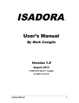
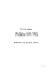
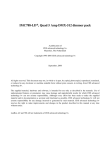
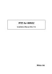
1
LAN-BOX
USER'S MANUAL (Rev. 1.10)
LAN-BOX
USER'S MANUAL (Rev.1.10)
REVISION HISTORY
Date
December 20, 1996
May 5,1998
Revision
1.00
1.10
Chapter
7.4
9
9.6
Explanation of revision
First edition
Solaris2.5.1 is added.
The reset command is added.
This chapter is added.
REVISION HISTORY
1
LAN-BOX
USER'S MANUAL (Rev.1.10)
CONTENTS
1.
INTRODUCTION................................................................................................................... 3
2.
SETUP OVERVIEW .............................................................................................................. 3
3.
TERMINOLOGY.................................................................................................................... 3
4.
CHECKING THE CONTENTS OF YOUR LAN-BOX PACKAGE........................................... 3
5.
SYSTEM CONFIGURATION AND COMPONENT NAMES ................................................... 4
6.
COMPONENT NAMES AND FUNCTIONS............................................................................ 5
7.
LAN-BOX SETTINGS ........................................................................................................... 7
7.1
ITEMS TO BE SPECIFIED................................................................................................................7
7.2
RS-232C TERMINAL-BASED SETTING PROCEDURE.....................................................................8
7.3
TELNET COMMAND-BASED SETTING PROCEDURE ...................................................................10
7.4
IP ADDRESS SETTING USING THE PING COMMAND..................................................................12
8.
CONNECTOR SPECIFICATIONS....................................................................................... 15
8.1
POWER SUPPLY JACK .................................................................................................................15
8.2
TERMINAL CONNECTOR ..............................................................................................................15
9.
LAN-BOX SETTING COMMANDS...................................................................................... 16
9.1
HELP (?) ........................................................................................................................................16
9.2
VER................................................................................................................................................16
9.3
SET................................................................................................................................................16
9.4
SAVE .............................................................................................................................................17
9.5
QUIT ..............................................................................................................................................17
9.6
RESET ...........................................................................................................................................17
10.
TROUBLESHOOTING ........................................................................................................ 18
CONTENTS
2
LAN-BOX
USER'S MANUAL (Rev.1.10)
1. INTRODUCTION
This manual describes the use of the LAN-BOX. The LAN-BOX is used to connect the RTE series
ICE to an engineering workstation (EWS) over a LAN.
2. SETUP OVERVIEW
This section briefly describes the setup required to enable the use of the LAN-BOX. Setup is
divided into two main phases. In the first phase, the LAN-BOX is set up (as described in this
manual). In the second phase, the RTE for UNIX is set up (as described in the "RTE for UNIX
Setup Manual").
1.
Set up the LAN-BOX.
2.
Set up RTE for UNIX.
3.
Specify the PATH and RTE4UNIX environment variables (by registering them
with .cshrrc).
4.
Specify the ICE type and LAN-BOX IP address to be used, by executing the "setrte"
command.
5.
Confirm the connection between the LAN-BOX and ICE by executing the "rte4unix -d"
command.
This manual focuses on step 1. Refer to the "RTE for UNIX Setup Manual" for details of steps 2 to
5.
3. TERMINOLOGY
This manual uses the following network-related terms.
MAC address
:
Stands for "media access control address." This is the physical address of
an individual hardware unit connected to a LAN. The user is not allowed to
change a physical address. Such an address is also known as an Ethernet
address.
The MAC address of the LAN-BOX is indicated on a label on the rear of the
unit. It can also be displayed, by executing either the "set" command (if the
LAN-BOX was connected using an RS-232C terminal) or the TELNET
command.
IP address
:
Stands for "Internet protocol address." This is a logical address, assigned to
an individual host that includes the LAN-BOX.
The user is requested to
assign it.
4. CHECKING THE CONTENTS OF YOUR LAN-BOX PACKAGE
After opening your LAN-BOX package, check that none of the items listed below is missing. If any
item is found to be missing or damaged, contact the dealer from whom you purchased the LANBOX.
* LAN-BOX main unit
* LAN-BOX AC adaptor (5 V), RTE-PS01
* ICE connection cable (with 36-pin connectors at both ends)
* RTE for UNIX setup CD-ROM
* User's manual (this manual)
* RTE for UNIX Setup Manual
INTRODUCTION/SETUP OVERVIEW/TERMINOLOGY/CHECKING THE CONTENTS OF YOUR LAN-BOX PACKAGE
3
LAN-BOX
USER'S MANUAL (Rev.1.10)
5. SYSTEM CONFIGURATION AND COMPONENT NAMES
This chapter describes the system configuration and names of component.
EWS
HUB
AC adaptor
LAN-BOX
ICE
LAN-BOX
ICE connection cable
LAN-BOX
: Unit used to connect the ICE to a LAN. It is provided with a 10BASE-T
connector to enable its connection to a LAN.
EWS
: Computer used to run a debugger. It is connected to the ICE via the LAN.
ICE
: RTE series ICE
RTE for UNIX, software for connecting the ICE, runs on the EWS.
ICE connection cable: Cable used to connect the LAN-BOX to the ICE. This cable is provided
with the LAN-BOX.
AC adaptor
: AC adaptor used to supply 5-V power to the LAN-BOX or ICE. Both the
LAN-BOX and ICE are connected to the same RTE-PS01.
SYSTEM CONFIGURATION AND COMPONENT NAMES
4
LAN-BOX
USER'S MANUAL (Rev.1.10)
6. COMPONENT NAMES AND FUNCTIONS
This chapter illustrates the LAN-BOX and describes the names and functions of its components.
LAN status LEDs
LAN connector
Status LEDs
Power supply jack
Power supply LED
5V
POWER
GND
3
10BASE-T
1
STATUS
4 2
L
P
A
C
LAN
ICE
RS232C
SWITCH
LAN-BOX
RESET
Mode switch
Reset switch
Terminal connector
ICE connector
Reset switch (RESET)
This switch is used to reset the LAN-BOX. It is normally not used, except when setting up
an IP address by using the PING command.
Mode switch (SWITCH)
This switch is used to specify the operation mode. It is normally not used, except when
setting up an IP address by using the PING command. (See Section 7.4.) All of its switches
must be left in their factory-set positions, that is, in the OFF position (with their notches to
the top).
LH4
1
2
3
4
2
OFF
ON
LAN connector (10BASE-T)
This connector is used to attach the LAN 10BASE-T cable.
ICE connector (ICE)
This connector is used for connection to the ICE.
Power supply jack
This is the power supply connector. See Section 8.1 for the specifications of the power
supply.
Connect only the supplied AC adaptor (RTE-PS01) to this power supply
jack. Do not attempt to use any other power supply.
Terminal connector (RS232-C)
This connector is used to connect the RS-232C terminal to be used to set the IP address.
See Section 8.2 for an explanation of how to attach the relevant cable.
Power supply LED (POWER)
This LED lights to indicate when power is being supplied to the LAN-BOX.
COMPONENT NAMES AND FUNCTIONS
5
LAN-BOX
USER'S MANUAL (Rev.1.10)
LAN status LEDs (LAN)
These LEDs indicate the status of the LAN. Their functions are listed below:
Code
L
A
C
P
Color
Green
Green
Red
Red
Name
Link
Active
Collision
Polarity
Description
Lights while the LAN cable is connected.
Lights when a packet is being transmitted over the LAN.
Lights if a packet collision occurs on the LAN.
Lights if a packet of the opposite polarity is received. This
indicator should not light during normal operation.
Status LEDs (STATUS)
These LEDs indicate the operation status of the LAN-BOX. Their functions are listed below.
In this table,
indicates an LED that is lit, while
indicates an LED that is off.
LED status
4
3
2
1
←→
Description
The LAN-BOX is waiting to be connected to the host. It has
yet to be connected for the first time.
The LAN-BOX is connected to the host.
←→
←→
←→
Others
The LAN-BOX is waiting to be connected to the host. It has
previously been connected.
The LAN-BOX is in IP address setting mode, as set with the
PING command. In this mode, the LAN-BOX cannot accept a
connection request from the host. (See Section 7.4.)
Undefined. Check the setting of the mode switch.
COMPONENT NAMES AND FUNCTIONS
6
LAN-BOX
USER'S MANUAL (Rev.1.10)
7. LAN-BOX SETTINGS
Before the LAN-BOX can be used, the following items, with the exception of the gateway address,
must be set.
IP address
Subnet mask
Gateway address
The settings made here will be saved into flash-ROM (rewritable ROM) in the LAN-BOX. The IP
address setting can be made using any of the three methods listed below:
Setting method
Merit
Restriction
Using the PING
No preparation is required.
The LAN-BOX must be connected
command
directly to the host (without using a
gateway).
Using the TELNET
No preparation is required.
This method cannot be used to set
command
up the LAN-BOX for the first time.
It can be used only to change a
previously set IP address.
Using an RS-232C
This method can be used
An RS-232C terminal and cable
terminal
regardless of the state of
are required.
the LAN-BOX.
The subnet mask and gateway address can be specified using either an RS-232C terminal or the
TELNET command after the IP address is specified.
Prior to using the LAN-BOX for the first time, an RS-232C terminal must be used to make all the
necessary settings. Alternatively, the PING command can be used to specify the IP address, after
which the TELNET command can be used to specify the other required settings.
7.1 ITEMS TO BE SPECIFIED
The following table lists the items that must be specified for the LAN-BOX.
Item
IP address
Subnet mask
Gateway address
Description
IP address of the LAN-BOX
A subnet mask should be specified.
If a gateway is used between the LAN-BOX and host, specify its
address. When there is no gateway, "0.0.0.0" should be specified.
LAN-BOX SETTINGS
7
LAN-BOX
USER'S MANUAL (Rev.1.10)
7.2 RS-232C TERMINAL-BASED SETTING PROCEDURE
The following procedure is used to set up the LAN-BOX by connecting it to an RS-232C terminal or
to terminal software running on a personal computer or EWS.
See Section 8.2 for the specifications of the RS-232C cable to be used and the related
communication conditions.
1. Connect the LAN-BOX to the RS-232C terminal, using a reverse cable.
2. Ensure that all the switches of the LAN-BOX mode switch are set to the OFF position (with
their notches to the top).
LH4
1
2
3
4
2
OFF
ON
3. Connect the AC adaptor to the power supply jack of the LAN-BOX, and turn on the power.
Ensure that the LAN-BOX status LEDs blink as shown below.
←→
4. Start the RS-232C terminal, then set the communication conditions: 9600 bps, 8 bits, no
parity bit, 1 start bit, 1 stop bit, hardware flow control).
5. Enter a return code from the RS-232C terminal.
Check whether the "rte>" prompt
appears.
6. Enter the following underlined commands to specify the respective addresses. In this
example, "0.0.0.0" is specified for the gateway address because no gateway is used.
←A return is entered.
Type HELP for help.
rte >set
←Displays the current settings.
Ethernet Address: 00-60-71-F0-01-01
IP Address
: 192.168.1.1
Subnet Mask
: 255.255.255.0
Gateway Address: 0.0.0.0
rte >set IP=xxx.xxx.xxx.xxx
←Specifies the IP address, in decimal.
rte >set MASK=yyy.yyy.yyy.yyy ←Specifies the subnet mask, in decimal.
rte >set GATE=0.0.0.0
←Specifies the gateway address, in decimal.
rte >set
←Confirms the specified information.
Ethernet Address: 00-60-71-F0-01-01
IP Address
: xxx.xxx.xxx.xxx
Subnet Mask
: yyy.yyy.yyy.yyy
Gateway Address: 0.0.0.0
rte >save
←Writes the specified information to flash-ROM and resets the LAN-BOX.
Ethernet Address: 00-60-71-F0-01-01
IP Address
: xxx.xxx.xxx.xxx
Subnet Mask
: yyy.yyy.yyy.yyy
Gateway Address: 0.0.0.0
Save IP Address...
Reset NetServer...
7. Connect the LAN-BOX to the LAN and, from the host, enter the TELNET command for the
specified IP address.
If the LAN-BOX is connected to the host by execution of the
TELNET command, and the "rte>" prompt appears, this means that the IP address has
been set up correctly. See Section 7.3 for an explanation of how to connect the LAN-BOX
to the host by using the TELNET command.
LAN-BOX SETTINGS
8
LAN-BOX
USER'S MANUAL (Rev.1.10)
If the power to the LAN-BOX is switched off before the "save" command
is executed, the specified information will not be saved; it will be lost.
Even if the subnet mask setting is incorrect, setting with the TELNET
command may be performed normally.
Double-check using the
"rte4unix -d" command. (Refer to the "RTE for UNIX Setup Manual.")
LAN-BOX SETTINGS
9
LAN-BOX
USER'S MANUAL (Rev.1.10)
7.3 TELNET COMMAND-BASED SETTING PROCEDURE
If an IP address has already been specified for the LAN-BOX and the TELNET command can be
used to connect the host to the LAN-BOX, this command can be used to change the setting. The
procedure is explained below.
1. Check that all the switches of the LAN-BOX mode switch are in the OFF position (with
their notches to the top).
LH4
1
2
3
4
2
OFF
ON
2. Connect the LAN cable to the LAN-BOX, then turn on the power to the LAN-BOX. Check
that the status LEDs on the LAN-BOX blink as shown below. Also, check whether the L
LAN status LED lights.
←→
3. Execute the TELNET command from the host to connect it to the LAN-BOX using the
current IP address.
4. Enter the following underlined commands to specify the respective addresses. In this
example, the SunOS TELNET command is used. "0.0.0.0" is specified as the gateway
address because no gateway is used.
Sun[20]:telnet
←The TELNET command is started.
telnet> open 192.168.1.1
←Connects to the LAN-BOX.
Trying 192.168.1.1 ...
Connected to 192.168.1.1.
Escape character is '^]'.
RTE NetServer Version 1.01.0.
Copyright (c) 1996 Midas lab, Inc. All rights reserved.
rte >set
←Displays the current settings.
Ethernet Address: 00-60-71-F0-01-01
IP Address
: 192.168.1.1
Subnet Mask
: 255.255.255.0
Gateway Address : 0.0.0.0
rte >set IP=xxx.xxx.xxx.xxx
←Specifies the IP address, in decimal.
rte >set MASK=yyy.yyy.yyy.yyy ←Specifies the subnet mask, in decimal.
rte >set GATE=0.0.0.0
←Specifies the gateway address, in decimal.
rte >set
←Confirms the specified information.
Ethernet Address: 00-60-71-F0-01-01
IP Address
:
Subnet Mask
:
Gateway Address :
rte >save
Ethernet Address:
xxx.xxx.xxx.xxx
yyy.yyy.yyy.yyy
0.0.0.0
←Writes the specified information to flash-ROM and resets the LAN-BOX.
00-60-71-F0-01-01
IP Address
: xxx.xxx.xxx.xxx
Subnet Mask
: yyy.yyy.yyy.yyy
Gateway Address : 0.0.0.0
Save IP Address...
Reset NetServer....
Connection closed by foreign host.
Sun[21]:
←The LAN-BOX is reset and disconnected → execution of the
TELNET command ends.
5. Enter the TELNET command from the host, specifying the newly set IP address. If, when
the host is connected to the LAN-BOX by executing the TELNET command, the "rte>"
prompt appears, this indicates that the IP address has been set up correctly.
LAN-BOX SETTINGS
10
LAN-BOX
USER'S MANUAL (Rev.1.10)
If the power to the LAN-BOX is switched off before the "save" command
is executed, the specified information will not be saved; it will be lost.
The TELNET command cannot be used to connect the host to the LANBOX, unless the result of ANDing the IP address of the network
connected to the LAN-BOX with the subnet mask matches the result of
ANDing the IP address of the LAN-BOX with the subnet mask.
Even if the subnet mask setting is incorrect, setting with the TELNET
command may be performed normally. Double-check by using the
"rte4unix -d" command. (Refer to the "RTE for UNIX Setup Manual.")
Note that the displayed version number may differ from that shown in
this example.
LAN-BOX SETTINGS
11
LAN-BOX
USER'S MANUAL (Rev.1.10)
7.4 IP ADDRESS SETTING USING THE PING COMMAND
The following procedure is used to specify the IP address of the LAN-BOX, based on the PING and
ARP commands of the host. This procedure can be used to specify only the IP address. The
TELNET command is used to make the other settings.
The formats of the PING and ARP commands vary slightly from host to host. This example covers
the procedures for each of three different hosts: Solaris2.5.1, SunOS 4.1.x, HP-UX 9.x, and
Windows 95.
1. Make a note of the MAC address (00:60:71:nn:nn:nn) provided on the label on the rear of
the LAN-BOX.
2. Set switch 1 of the LAN-BOX mode switch to ON (with its notch to the bottom), and the
other switches (2 to 4) to OFF (with their notches to the top). Then, press the reset switch.
LH4
1
2
3
4
2
OFF
ON
3. Connect the LAN cable to the LAN-BOX, and supply power to the LAN-BOX. Check that
the status LEDs on the LAN-BOX blink as shown below. Also, check that the L LAN status
LED lights.
←→
4. If the host is a UNIX machine, log on from the root (superuser). If the host is a Windows
95 machine, switch to a DOS window.
5. Enter the following underlined commands to specify the IP address. This example assigns
IP address "xxx.xxx.xxx.xxx" to that LAN-BOX having MAC address "00:60:71:nn:nn:nn".
The MAC address is in hexadecimal, while the IP address is in decimal. After setting the
IP address, enter the PING command again to confirm that the desired IP address has
been set correctly.
Case 1: The host is running Solaris 2.5.1.
Solaris[20]:arp -s xxx.xxx.xxx.xxx 00:60:71:nn:nn:nn temp
←The "arp" command associates the
MAC address with the IP address.
Solaris[21]:arp -a
←Confirms the setting made using the
le0 xxx.xxx.xxx.xxx 255.255.255.255 00:60:71:nn:nn:nn
"arp" command.
←Check that the list contains the items
set above.
Solaris[22]:ping xxx.xxx.xxx.xxx
←Sends a packet to the assigned IP
xxx.xxx.xxx.xxx is alive
Solaris[23]:ping xxx.xxx.xxx.xxx
xxx.xxx.xxx.xxx is alive
address. The LAN-BOX may not
become alive here.
←The PING command is issued again to
confirm that the LAN-BOX is alive.
LAN-BOX SETTINGS
12
LAN-BOX
USER'S MANUAL (Rev.1.10)
Case 2: The host is running SunOS 4.1.x.
Sun[20]:arp -s xxx.xxx.xxx.xxx 00:60:71:nn:nn:nn temp
←The "arp" command associates the
MAC address with the IP address.
Sun[21]:arp -a
←Confirms the setting made using the
? (xxx.xxx.xxx.xxx) at 0:60:71:nn:nn:nn
"arp" command.
←Check that the list contains the items
set above.
Sun[22]:ping xxx.xxx.xxx.xxx
←Sends a packet to the assigned IP
xxx.xxx.xxx.xxx is alive
address. The LAN-BOX may not
become alive here.
←The PING command is issued again to
Sun[23]:ping xxx.xxx.xxx.xxx
xxx.xxx.xxx.xxx is alive
confirm that the LAN-BOX is alive.
Case 3: The host is running HP-UX 9.x.
Hp[20]:arp -s xxx.xxx.xxx.xxx 00:60:71:nn:nn:nn temp
←The "arp" command associates the MAC
address with the IP address.
Hp[21]:arp -a
? (xxx.xxx.xxx.xxx) at 0:60:71:nn:nn:nn ether
←Confirms the setting made using the "arp" command.
←Checks that the list contains the items set
above.
←Sends a packet to the assigned IP address.
Hp[22]:ping xxx.xxx.xxx.xxx 64 1
PING xxx.xxx.xxx.xxx: 64 byte packets
64 bytes from xxx.xxx.xxx.xxx: icmp_seq=0. time=1. ms
In some cases, packet loss may occur here.
----xxx.xxx.xxx.xxx PING Statistics---1 packets transmitted, 1 packets received, 0% packet loss
round-trip (ms) min/avg/max = 1/1/1
←The PING command is issued again to
Hp[23]:ping xxx.xxx.xxx.xxx 64 1
PING xxx.xxx.xxx.xxx: 64 byte packets
64 bytes from xxx.xxx.xxx.xxx: icmp_seq=0. time=1. Ms
confirm that no packet has been lost.
----xxx.xxx.xxx.xxx PING Statistics---1 packets transmitted, 1 packets received, 0% packet loss
round-trip (ms) min/avg/max = 1/1/1
Case 4: The host is running Windows 95.
C:\>arp -s xxx.xxx.xxx.xxx 00-60-71-nn-nn-nn
←The "arp" command associates the MAC
address with the IP address.
←Confirm the setting made using the "arp"
C:\>arp -a
command.
Interface: yyy.yyy.yyy.yyy
Internet Address Physical Address
xxx.xxx.xxx.xxx
00-60-71-nn-nn-nn
Type
static
←Check that the list contains the items set
above.
C:\>ping xxx.xxx.xxx.xxx
←Sends a packet to the assigned IP address.
A time-out may occur here.
Pinging xxx.xxx.xxx.xxx with 32 bytes of data:
Reply from 203.180.66.2: bytes=32 time=2ms TTL=255
C:\>ping xxx.xxx.xxx.xxx
←The PING command is issued again to
confirm that no time-out occurs.
Pinging xxx.xxx.xxx.xxx with 32 bytes of data:
Reply from 203.180.66.2: bytes=32 time=2ms TTL=255
LAN-BOX SETTINGS
13
LAN-BOX
USER'S MANUAL (Rev.1.10)
6. Set all the switches of the LAN-BOX mode switch to the OFF position (with their notches
to the top), then press the reset switch. Confirm that the status LEDs blink as shown
below.
LH4
1
2
3
4
2
OFF
ON
←→
7. Set the subnet mask and gateway address, using the TELNET command. (See Section
7.3.)
If the IP address is to be set up using the PING command, there must
be no gateway between the host on which the PING command is
executed and the LAN-BOX. The host and the LAN-BOX must be
connected to the same node.
If an error occurs upon the execution of the "arp -s" command, issue
the PING command for the existing host IP address, then execute the
"arp -s" command again. This symptom occurs because, if there is no
correspondence between the MAC address and IP address, the "arp -s"
command may not be accepted. Issuing the PING command for an
existing host causes the MAC-IP correspondence to be registered,
making it possible to execute the "arp -s" command normally.
When the first PING command is issued to set up the IP address, and
the LAN-BOX receives the relevant packet and registers the IP address,
the status LEDs on the LAN-BOX do not blink for 2 or 3 seconds.
If the IP address specified in the PING command is equal to the current
setting, the LAN-BOX does not register the new IP address. So, issuing
the PING command repeatedly for a single address has no detrimental
effect.
LAN-BOX SETTINGS
14
LAN-BOX
USER'S MANUAL (Rev.1.10)
8. CONNECTOR SPECIFICATIONS
This chapter describes the specifications of the LAN-BOX connectors.
8.1 POWER SUPPLY JACK
The power supply jack is rated as follows:
Voltage
: 5V
Current
: 2 A (maximum)
Mating connector : Type A (5.5 mm diameter)
Polarity
: Center ground
+5V
GND
GND
+5V
Applicable power supply model: RTE-PS01
Never attempt to connect other than the supplied AC adaptor to the
power supply jack.
8.2 TERMINAL CONNECTOR
This section describes the specifications of the terminal connector (RS-232C connector). This
connector is a 9-pin D-SUB connector, like that which is commonly used for the RS-232C interface
on personal computers. The following table lists the pin arrangement of the connector when it is
used on a typical reverse cable connected to an EWS or personal computer.
1
2
6
3
7
4
8
5
9
Pin Arrangement
Pin
number
1
2
3
4
5
6
7
8
9
Signal name
NC
RxD(RD)
TxD(SD)
DTR(DR)
GND
DSR(ER)
RTS(RS)
CTS(CS)
NC
Input/
output
Input
Output
Output
Input
Output
Input
Pin number on host side
D-SUB9
D-SUB25
3
2
1, 6
5
4
8
7
2
3
6, 8
7
20
5
4
Cable Connection
Item
Baud rate
Number of bits
Parity
Start bit
Stop bit
Flow control
Local echo
Setting
9600 bps
8 bit
None
1 bit
1 bit
RTS/CTS (hardware flow control)
None
Communication Conditions
CONNECTOR SPECIFICATIONS
15
LAN-BOX
USER'S MANUAL (Rev.1.10)
9. LAN-BOX SETTING COMMANDS
This chapter describes the setting commands used when the LAN-BOX is connected using the
TELNET command or an RS-232C terminal. The setting commands are listed below:
Command name
HELP,?
VER
SET
SAVE
QUIT
RESET
Description
Provides help.
Displays version information.
Sets or displays addresses and
other information.
Saves the set information.
Terminates the connection.
Reset all connection.
9.1 HELP (?)
<Format>
HELP
<Explanation>
This command lists the available commands.
<Format>
VER
<Explanation>
This command displays the LAN-BOX version.
<Format>
SET [<parameter> = <value>]
<Explanation>
This command sets various parameters.
9.2 VER
9.3 SET
If no arguments are specified, the
command displays the current settings together with the MAC address (Ethernet
address). The command has the following three parameters. The information
specified using the SET command becomes effective only after it has been saved
by executing the SAVE command.
Parameter
IP
MASK
GATE
<Example>
Description
Causes the IP address of the LAN-BOX to be set. Each part of
the IP address is a decimal number, delimited by a period.
Causes the subnet mask to be set. Each part of the subnet
mask is a decimal number, delimited by a period.
Causes the IP address of the gateway to be set. Each part of
the IP address is a decimal number, delimited by a period.
When no gateway is used, "0.0.0.0" must be specified.
SET IP=192.168.1.1
SET MASK=255.255.255.192
SET GATE=192.168.1.4
LAN-BOX SETTING COMMANDS
16
LAN-BOX
USER'S MANUAL (Rev.1.10)
9.4 SAVE
<Format>
SAVE
<Explanation>
This command saves the information, set using the SET command, into flashROM (rewritable ROM), then resets the LAN-BOX.
The information specified
using the SET command becomes effective only after it has been saved using the
SAVE command.
If the LAN-BOX has been connected using the TELNET command, executing the
SAVE command resets the LAN-BOX and disconnects it from the host.
To
reestablish the connection, use a newly set IP address.
9.5 QUIT
<Format>
QUIT
<Explanation>
If the LAN-BOX has been connected using the TELNET command, executing the
QUIT command terminates the connection between the LAN-BOX and host. If
the LAN-BOX has been connected using an RS-232C terminal, executing the
QUIT command has no effect.
9.6 RESET
<Format>
RESET
<Explanation>
This command reset the LAN-BOX. The connection with the host can be
disconnected forcibly by this command.
LAN-BOX SETTING COMMANDS
17
LAN-BOX
USER'S MANUAL (Rev.1.10)
10. TROUBLESHOOTING
[Symptom]
[Measures]
The LAN-BOX cannot be connected using an RS-232C terminal (or terminal
software).
• Check that the RS-232C cable between the terminal and LAN-BOX is
attached correctly. (See Section 8.2.)
• Check that the communication conditions specified for the terminal are set
correctly. (See Section 8.2.)
[Symptom]
[Measures]
The LAN-BOX cannot be connected using the TELNET command.
• Check that all the switches of the LAN-BOX mode switch are set to the OFF
position (with their notches to the top).
• Check that the IP address of the LAN-BOX is set correctly, by connecting an
RS-232C terminal.
• If there is a gateway between the LAN-BOX and the host from which the
TELNET command is entered, the IP address of the gateway must be set on
the LAN-BOX. Check that the gateway address is set on the LAN-BOX, by
connecting an RS-232C terminal. Alternatively, connect the LAN-BOX to a
node for which no gateway is necessary, and observe whether operation is
satisfactory.
[Symptom]
The LAN-BOX can be connected by using the TELNET command. It cannot,
however, be connected using the "rte4unix -d" command.
• Check whether the net mask for the LAN-BOX is set correctly. The current
setting is displayed by connecting the LAN-BOX by executing the TELNET
command and keying in "SET."
• Check that the IP address set using the "setrte" command is correct. The
current setting is displayed by entering the "setrte -s" command.
• If the LAN-BOX host name rather than the IP address is specified using the
"setrte" command, check that the LAN-BOX host name is set in the DNS
correctly. Alternatively, specify the IP address, instead of the host name,
with the "setrte" command.
[Measures]
TROUBLESHOOTING
18
LAN-BOX
USER'S MANUAL (Rev.1.10)
• Memo -
LAN-BOXUSER'S MANUAL
M672MNL03
19