1
ISADORA
®
User’s Manual
By Mark Coniglio
Version 1.5
August 2013
© 2002-2013 Mark F. Coniglio
all rights reserved
Isadora Manual
1
TABLE OF CONTENTS
TABLE OF CONTENTS......................................................................2 ISADORA – OVERVIEW ..................................................................18 What is Isadora? ......................................................................................... 18 QUICK START..................................................................................19 REGISTRATION PROCEDURE .......................................................21 Step 1: Download ......................................................................................................................... 21 Step 2: Purchase............................................................................................................................ 21 Step 3: Register............................................................................................................................. 21 Step 3a: Register – Standard Version ........................................................................................... 21 Step 3b: Register – USB Key Version.......................................................................................... 23 Preparing Your Computer .......................................................................... 25 Download the Tutorials ................................................................................................................ 25 Online Video Tutorials ................................................................................................................. 25 Basic System Requirements ......................................................................................................... 25 Installing MIDI Interface Hardware & Drivers ............................................................................ 26 Setting Isadora Preferences .......................................................................................................... 26 Tutorial 1: Playing a Movie......................................................................... 29 Creating a New File ...................................................................................................................... 29 Creating Scenes ............................................................................................................................ 29 Importing Media ........................................................................................................................... 30 Using Isadora Actors .................................................................................................................... 31 Tutorial 2: Changing Actor Settings ......................................................... 34 Tutorial 3: Interactive Control.................................................................... 36 Tutorial 4: Live Video Input........................................................................ 38 Tutorial 5: Real Time Video Processing ................................................... 40 Tutorial 6: Sound ........................................................................................ 43 Tutorial 7: Using Scenes............................................................................ 46 Tutorial 8: Fine Tuning Links and Actors ................................................. 49 Understanding Property Types ..................................................................................................... 49 Understanding Value Scaling ....................................................................................................... 50 Isadora Manual
2
Initializing Property Values.......................................................................................................... 51 Tutorial 9: More Real Time Video Processing ......................................... 52 Video Mixer.................................................................................................................................. 53 Luminance Key............................................................................................................................. 53 Displace ........................................................................................................................................ 54 Video Feedback ............................................................................................................................ 54 Tutorial 10: Making Your Own Actors....................................................... 55 Adding Your User Actor to the Toolbox...................................................................................... 58 Using the Confirm User Actor Edit Dialog (v1.3) ....................................................................... 59 Sharing Your User Actors ............................................................................................................ 60 Tutorial 11: Getting the Most From the Projector (v1.3) ......................... 61 OPTIMIZING FOR SPEED................................................................65 ISADORA REFERENCE...................................................................71 Importing & Managing Media..................................................................... 71 Media Window Basics.................................................................................................................. 71 Importing Media ........................................................................................................................... 72 Selecting Media References ......................................................................................................... 73 Managing Media........................................................................................................................... 74 Using the Scene List .................................................................................. 76 Activating & Deactivating Scenes................................................................................................ 77 Selecting Scenes ........................................................................................................................... 77 Adding and Removing Scenes...................................................................................................... 77 Reordering Scenes ........................................................................................................................ 78 Renaming Scenes.......................................................................................................................... 79 Changing the Width of a Scene .................................................................................................... 79 Editing Scenes and Using Actors ............................................................. 79 Adding New Actors to a Scene / Using the Toolbox ................................................................... 80 Selecting and Deleting Actors ...................................................................................................... 81 Organizing Actors......................................................................................................................... 81 Editing Actors............................................................................................................................... 82 Making Links Between Actors ..................................................................................................... 82 Mutable Inputs and Outputs ......................................................................................................... 84 Getting Help for an Actor ............................................................................................................. 85 Navigating Inside the Scene Editor .............................................................................................. 86 Scaling Values Between Outputs and Inputs................................................................................ 86 Presetting a Property Value .......................................................................................................... 89 Editing Property Values................................................................................................................ 89 Collapsing/Expanding Actors....................................................................................................... 90 User Actors & Macros: Creating Your Own Actors ................................. 92 User Actor Synchronization Feature (v1.3).................................................................................. 93 Considerations for User Actors Created Before v1.3 ................................................................... 94 Creating and Editing a User Actor ............................................................................................... 95 Creating and Editing User Inputs and Outputs ............................................................................. 96 Isadora Manual
3
User Input/Output Reordering (v1.3) ........................................................................................... 97 Saving the User Actor After an Edit (v1.3) .................................................................................. 98 Converting a Macro to a User Actor (v1.3).................................................................................. 99 Adding User Actors to the Toolbox ............................................................................................. 99 Storing and Recalling Scenes with Snapshots...................................... 101 Storing and Recalling Snapshots ................................................................................................ 102 Disabling Snapshot Recall for Specific Actors (v1.3)................................................................ 103 Using Control Panels................................................................................ 104 Overview .................................................................................................................................... 104 Creating/Deleting Control Panels using Split & Join ................................................................. 106 Showing/Hiding Control Panels ................................................................................................. 107 Using / Editing Control Panels ................................................................................................... 107 Adding New Controls to a Control Panel................................................................................... 108 Linking a Control to an Actor Input or Output........................................................................... 108 Unlinking a Control from an Actor Input or Output .................................................................. 110 Selecting and Deleting Controls ................................................................................................. 111 Using a Picture as a Background (v1.1) ..................................................................................... 111 Positioning, Sizing and Aligning Controls ................................................................................. 112 Editing Controls.......................................................................................................................... 113 Setting the font, font style and font size for a group of controls: ............................................... 114 Locking Controls ........................................................................................................................ 114 Using the Grid Snap Feature ...................................................................................................... 115 Changing a Control’s Settings .................................................................................................... 115 Setting Control Specific Options ................................................................................................ 116 Seeing the Control ID Associated with Controls........................................................................ 117 Using FreeFrame Plug-ins ....................................................................... 117 Saving Files as Run-Only (v1.1) .............................................................. 117 Isadora Preferences ................................................................................. 120 General Preferences .................................................................................................................... 120 Video Preferences....................................................................................................................... 123 Stage Preferences........................................................................................................................ 127 MIDI/Net Preferences................................................................................................................. 130 Warnings..................................................................................................................................... 132 Status Window: Monitoring Performance and External Input.............. 133 Performance................................................................................................................................ 133 Midi In Monitor .......................................................................................................................... 134 Live Input ................................................................................................................................... 134 DV Devices................................................................................................................................. 135 Cue Sheets ................................................................................................ 136 Creating The Cue Sheet .............................................................................................................. 136 Using the Cue Sheet ................................................................................................................... 138 Pausing and Resuming the Isadora Engine ........................................... 139 VIDEO & AUDIO OUTPUT .............................................................140 Isadora Manual
4
Compositing with the Projector (v1.3) .................................................... 140 Layering & Blending .................................................................................................................. 140 Distorting the Image ................................................................................................................... 141 Alpha Channels........................................................................................................................... 142 YUV Video Processing (v1.1) ................................................................... 143 Working with YUV .................................................................................................................... 144 Recording the Stage Output .................................................................... 145 Rendering Complicated/High-Resolution Scenes ...................................................................... 145 Adjusting the Recording Settings ............................................................................................... 145 Adjusting the Compression Settings........................................................................................... 146 Recording Isadora’s Output........................................................................................................ 148 Mirroring Video to an External Device (v1.1) ........................................................................... 148 Outputting to a Video Projector .............................................................. 149 Mac OS X ................................................................................................................................... 149 Windows 7 .................................................................................................................................. 150 Windows Vista & XP ................................................................................................................. 151 Isadora ........................................................................................................................................ 152 Projectors in Performance: Two Critical Tips ............................................................................ 152 Using the Matrox Dual/TripleHead2Go ................................................... 152 Using External Multi-Channel Sound Output ......................................... 153 Installing Drivers ........................................................................................................................ 154 Setting Up Multi-Channel Sound With the Sound Player .......................................................... 154 Using Multi-Channel Sound with Movies.................................................................................. 156 Using Multi-Channel Sound with Sound Files........................................................................... 157 Creating a Multi-Channel Audio Movie Using QuickTime Player Pro ..................................... 158 Isadora & CoreAudio (v1.2 - MacOS X Only) .......................................... 159 Setting Up for Multi-Channel Sound in Mac OS X ................................................................... 159 Manipulating Pre-Recorded Sound - Tutorial ............................................................................ 160 Spatialized Sound - Tutorial ....................................................................................................... 161 Setting Up for Multi-Channel Sound in Windows Vista............................................................ 162 LIVE VIDEO & AUDIO INPUT ........................................................164 Live Capture Settings Window (v1.3) ........................................................................................ 164 Starting/Stopping Live Capture .................................................................................................. 166 Verifying Live Capture............................................................................................................... 167 Interactively Starting or Stopping Capture & Recording Capture Input .................................... 167 Controlling Video Capture Performance .................................................................................... 168 Capturing Video and Audio To Disk........................................................ 170 Starting Capture To Disk ............................................................................................................ 170 Stopping Capture To Disk .......................................................................................................... 171 Specifying the Location on Disk for Captured Media................................................................ 171 Deleting Captured Media............................................................................................................ 172 COMMUNICATING WITH EXTERNAL DEVICES..........................173 Isadora Manual
5
MIDI Input and Output .............................................................................. 173 Hardware Interface & Drivers .................................................................................................... 173 Midi Setup .................................................................................................................................. 173 Isadora Virtual MIDI Inputs & Outputs (v1.1 MacOS) ............................................................. 175 Open Sound Control (OSC) (v1.1) ........................................................... 176 How Open Sound Control Communicates ................................................................................. 176 Receiving Open Sound Control Packets..................................................................................... 177 Adding Custom Open Sound Control (OSC) Addresses............................................................ 178 Transmitting Open Sound Control Packets ................................................................................ 180 Transmitting/Receiving OSC Without a Router......................................................................... 180 Human Interface Device Input (HID) (v1.3) ............................................. 182 Setting up an HID ....................................................................................................................... 182 Serial Input/Output (v1.1) ......................................................................... 185 Hardware Interface & Drivers .................................................................................................... 185 Serial Port Setup ......................................................................................................................... 185 Input Data Parsing – Overview (v1.3)...................................................... 186 Text vs. Binary Actors................................................................................................................ 187 Data Parsing: Patterns................................................................................................................. 188 Data Parsing: Elements............................................................................................................... 188 Data Input: Parameter Assignment............................................................................................. 193 Data Input: Examples ................................................................................................................. 195 Data Output Formatting (v1.3) ................................................................. 195 2D Velocity (v1.1) ...................................................................................... 198 3D Ambient Light (v1.5)............................................................................ 199 3D Light Orientation (v1.1) ....................................................................... 200 3D Mesh Projector (v1.3) .......................................................................... 201 3D Mosaic (v1.3)........................................................................................ 203 3D Particles (v1.3) ..................................................................................... 206 3D Player.................................................................................................... 211 3D Projector (v1.3) .................................................................................... 214 3D Quad Distort (v1.1) .............................................................................. 217 3D Rect Project (v1.3) ............................................................................... 219 3D Renderer .............................................................................................. 222 Isadora Manual
6
3D Stage Options ...................................................................................... 223 3D Stage Orientation (v1.1)...................................................................... 224 3D Trackball (v1.5) .................................................................................... 225 3D Velocity (v1.3) ...................................................................................... 225 Absolute Value (v1.1) ............................................................................... 226 Activate Scene Amount (v1.1) ................................................................. 226 Activate Scene .......................................................................................... 228 Add Alpha Channel (v1.1) ........................................................................ 229 All Notes Off .............................................................................................. 230 Alpha Mask ................................................................................................ 230 Anything .................................................................................................... 232 Auto Fade .................................................................................................. 233 Background Color..................................................................................... 234 Blob Decoder (v1.1) .................................................................................. 234 Blob Minimum Distance (v1.5)................................................................. 236 Blob Target Proximity (v1.5) .................................................................... 237 Broadcaster ............................................................................................... 238 Buffer ......................................................................................................... 239 Calc Angle (v1.1) ....................................................................................... 241 Calc Angle 3D (v1.3) ................................................................................. 241 Calc Brightness (v1.1) .............................................................................. 242 Calc MBT.................................................................................................... 243 Calculator .................................................................................................. 244 Capture Control......................................................................................... 245 Isadora Manual
7
Capture To Disk ........................................................................................ 246 Character to Number ................................................................................ 247 Chop Pixels (v1.1) ..................................................................................... 247 Chopper (v1.1)........................................................................................... 248 Chroma Key............................................................................................... 250 Clock .......................................................................................................... 252 Color Maker ............................................................................................... 252 Color Maker RGB (v1.5)............................................................................ 253 Color to HSB (v1.5) ................................................................................... 254 Color to RGB ............................................................................................. 254 Colorizer .................................................................................................... 255 Comparator................................................................................................ 256 Compare Guarded (v1.1) .......................................................................... 257 Contrast Adjust (v1.1)............................................................................... 257 Control Watcher ........................................................................................ 258 Counter ...................................................................................................... 259 Crop............................................................................................................ 260 Current Scene (v1.5)................................................................................. 261 Curvature ................................................................................................... 261 Data Array.................................................................................................. 262 Deactivate Scene ...................................................................................... 265 Decay Generator ....................................................................................... 266 Desaturate ................................................................................................. 267 Difference .................................................................................................. 267 Isadora Manual
8
Displace ..................................................................................................... 268 Dither.......................................................................................................... 270 Dots ............................................................................................................ 271 DV Device Control .................................................................................... 273 Ease In-Out 2D .......................................................................................... 273 Effect Mixer ............................................................................................... 274 Enter Scene Trigger ................................................................................. 276 Enter Scene Value .................................................................................... 277 Envelope Generator ................................................................................. 277 Envelope Generator++ ............................................................................. 279 Explode (v1.1)............................................................................................ 280 Eyes............................................................................................................ 281 Eyes++ (v1.3) ............................................................................................. 284 Filter ........................................................................................................... 287 Flip.............................................................................................................. 288 Float Counter (v1.3) .................................................................................. 289 Float to Integer (v1.3) ............................................................................... 290 Freeze ........................................................................................................ 291 Gate ............................................................................................................ 291 Gaussian Blur............................................................................................ 292 Get Media Count ....................................................................................... 292 Get Media Index (v1.1).............................................................................. 293 Global Keystone ....................................................................................... 294 HID Value Listener .................................................................................... 295 Isadora Manual
9
Hold Range ................................................................................................ 295 HSB to RGB ............................................................................................... 296 HSL Adjust................................................................................................. 297 Image Tile .................................................................................................. 297 Inside Range (v1.1) ................................................................................... 299 Integer Counter ......................................................................................... 300 Interlacer.................................................................................................... 300 Jump .......................................................................................................... 302 Jump++ ...................................................................................................... 303 Key Table Watcher.................................................................................... 304 Keyboard Watcher .................................................................................... 304 LanBox Channels (v1.1) ........................................................................... 305 LanBox RGB Out (v1.1) ............................................................................ 307 Limit-Scale Value ...................................................................................... 310 Limit Resolution........................................................................................ 311 Lines........................................................................................................... 312 Listener...................................................................................................... 313 Logical Calculator (v1.1) .......................................................................... 314 Lookup (v1.1)............................................................................................. 314 Loop Calculator......................................................................................... 315 Luminance Key ......................................................................................... 316 Math............................................................................................................ 318 Matrix Value Receive ................................................................................ 319 Matrix Value Send..................................................................................... 323 Isadora Manual
10
Matte........................................................................................................... 324 Matte++ ...................................................................................................... 325 Max Value Hold ......................................................................................... 327 Maximum ................................................................................................... 328 Media Percent to Time (v1.2) ................................................................... 328 Media Time to Percent (v1.2) ................................................................... 329 Midi Enable ................................................................................................ 329 Midi Player ................................................................................................. 330 Midi Show Control Watcher (v1.5)........................................................... 331 Min Value Hold .......................................................................................... 332 Mini Sequencer ......................................................................................... 332 Minimum .................................................................................................... 333 Mono Pressure Watcher........................................................................... 334 Motion Blur (v1.1)...................................................................................... 335 Mouse Watcher ......................................................................................... 336 Movie Player .............................................................................................. 337 Movie Player Direct................................................................................... 340 Movie Player VR ........................................................................................ 343 MTC Compare............................................................................................ 344 Multi Blocker ............................................................................................. 344 MultiMix (v1.1) ........................................................................................... 345 MultiVid ...................................................................................................... 346 Net Broadcaster ........................................................................................ 347 Note Off Watcher ...................................................................................... 348 Isadora Manual
11
Note On Watcher....................................................................................... 349 Number To Text (v1.3) .............................................................................. 350 Number To String (v1.2) ........................................................................... 350 OSC Listener (v1.3)................................................................................... 350 OSC Multi Transmit................................................................................... 351 OSC Transmit (v1.1).................................................................................. 352 Overlay Box ............................................................................................... 353 Panner........................................................................................................ 354 Pass Value (v1.1)....................................................................................... 355 Performance Monitor................................................................................ 356 Picture Player ............................................................................................ 356 Picture Preload.......................................................................................... 357 Pitch Bend Watcher .................................................................................. 358 Pitch Roll Yaw to Rotation (v1.3) ............................................................. 359 Point Tracker (v1.1)................................................................................... 360 Poly Pressure Watcher............................................................................. 360 Preload Scene (v1.3)................................................................................. 361 Program Change Watcher........................................................................ 362 Program Change Watcher........................................................................ 364 Projector (v1.3).......................................................................................... 365 Pulse Generator ........................................................................................ 367 Random...................................................................................................... 368 Real Time Watcher (v1.1) ......................................................................... 368 Recall Snapshot ........................................................................................ 369 Isadora Manual
12
Reflector (v1.5) .......................................................................................... 369 RGB to HSB (v1.5)..................................................................................... 370 Resizable Bkg............................................................................................ 370 RGB to YUV (v1.1) ..................................................................................... 371 Router ........................................................................................................ 371 Scale Value ................................................................................................ 372 Scaler (v1.1)............................................................................................... 373 Scanner...................................................................................................... 373 Scene Intensity (v1.3) ............................................................................... 374 Selector...................................................................................................... 375 Send Bank Select...................................................................................... 376 Send Control ............................................................................................. 376 Send HiRes Control .................................................................................. 377 Send MIDI Show Control .......................................................................... 378 Send Mono Pressure ................................................................................ 380 Send NonReg Param ................................................................................ 380 Send Note .................................................................................................. 381 Send Pitch Bend ....................................................................................... 382 Send Poly Pressure .................................................................................. 383 Send Program Change ............................................................................. 383 Send Raw MIDI .......................................................................................... 384 Send Raw Serial Data (v1.3)..................................................................... 385 Send Serial Data (v1.1) ............................................................................. 385 Send Sys Ex .............................................................................................. 386 Isadora Manual
13
Serial In Watcher Binary .......................................................................... 387 Serial In Watcher Text .............................................................................. 388 Set Modified (v1.5) .................................................................................... 389 Sequential Trigger .................................................................................... 389 Shapes (v1.3)............................................................................................. 390 Shimmer..................................................................................................... 391 Show-Hide Stages .................................................................................... 392 Simultaneity............................................................................................... 392 Slit Scan..................................................................................................... 393 Smoother (v1.1)......................................................................................... 393 Sound Frequency Watcher ...................................................................... 394 Sound Level Watcher ............................................................................... 396 Sound Movie Player.................................................................................. 397 Sound Player ............................................................................................. 400 Sound Preload........................................................................................... 402 Sound Level Watcher ............................................................................... 403 Speak Text (v1.3) ...................................................................................... 404 Sprite.......................................................................................................... 405 Stage Background (v1.2).......................................................................... 407 Stage Mouse Watcher (v1.3) .................................................................... 409 String Formatter (v1.2) ............................................................................. 411 String (v1.1) ............................................................................................... 411 Syphon To Video (v1.5) ............................................................................ 411 Syphon To Image (v1.5)............................................................................ 412 Isadora Manual
14
Syphon Stage Output (v1.5)..................................................................... 412 Table........................................................................................................... 413 Take Snapshot .......................................................................................... 413 Tap Tempo................................................................................................. 414 TCP In Watcher - Binary ........................................................................... 414 TCP In Watcher - Text............................................................................... 415 TCP Send Data .......................................................................................... 416 TCP Stream Control.................................................................................. 417 Text (v1.3) .................................................................................................. 418 Text Chopper............................................................................................. 418 Text Draw (v1.1) ........................................................................................ 419 Text Formatter (v1.3) ................................................................................ 420 Text Parser (v1.3) ...................................................................................... 421 Text Wrapper (v1.5) .................................................................................. 421 Text/ure ...................................................................................................... 422 The Edge.................................................................................................... 424 Threshold (v1.1) ........................................................................................ 425 Timer .......................................................................................................... 426 Time of Day (v1.1) ..................................................................................... 426 Toggle ........................................................................................................ 427 Trigger Delay............................................................................................. 427 Trigger Divider .......................................................................................... 428 Trigger Text (v1.3)..................................................................................... 429 Trigger String (v1.1).................................................................................. 429 Isadora Manual
15
Trigger Value ............................................................................................. 429 Update Snapshot ...................................................................................... 430 Value Delay Line ....................................................................................... 430 Value Select............................................................................................... 431 Video Delay ............................................................................................... 432 Video Fader ............................................................................................... 432 Video In Watcher....................................................................................... 433 Video Inverter............................................................................................ 434 Video Mixer................................................................................................ 434 Video Noise ............................................................................................... 435 Video Preload ............................................................................................ 436 Warp ........................................................................................................... 437 Wave Generator ........................................................................................ 438 YUV to RGB (v1.1) ..................................................................................... 439 Zoomer....................................................................................................... 440 CONTROLS REFERENCE .............................................................442 2D Slider .................................................................................................... 442 Background ............................................................................................... 444 Bin Picker .................................................................................................. 446 Button ........................................................................................................ 449 Comment ................................................................................................... 451 Dial (v1.1) ................................................................................................... 452 Edit Text (v1.1) .......................................................................................... 454 FPS ............................................................................................................. 455 Isadora Manual
16
Monitor....................................................................................................... 456 Number ...................................................................................................... 457 Popup Menu .............................................................................................. 458 Slider .......................................................................................................... 459 Stage Preview ........................................................................................... 462 Video Picker .............................................................................................. 464 Isadora Manual
17
Isadora – Overview
What is Isadora?
Isadora is a software program designed to allow interactive, real-time manipulation
of digital media, including pre-recorded video, live video, sound, standard MIDI
files and more. You create an Isadora program by linking together modules (called
actors in Isadora parlance), each of which perform a specific function on the media.
You make these programs interactive by linking actors to another type of module,
called a watcher, which looks for information from the outside world (i.e. MIDI
messages, mouse and keyboard actions, messages send over a Local Area
Network). The results are presented via the computer’s video displays, speakers, or
MIDI interfaces.
The design of Isadora is the result of over a dozen years of experience of creating
interactive works with my dance theater company Troika Ranch
(http://www.troikaranch.org), as well as my experience teaching numerous
workshops on integrating digital media into live performance. It reflects my own
desire for a flexible, powerful and reliable tool with which to make my own pieces,
and to create a friendly working environment for those who do not have extensive
computer experience.
Perhaps the most difficult aspect of Isadora is that a new file is a blank slate – it
won’t do anything for you until you begin to bring actors into the program and link
them together. For those just beginning, this can be a bit daunting. So, we have
supplied a complete set of tutorials that lead you through the process of creating
several Isadora programs. In addition, you will find several example files included
with the application. Looking at these may be the best place to start, as it will give
you a sense of what you can do with Isadora and how to begin using it.
On the other hand, those who have more experience with media manipulation
software may want to head directly for the Quick Start section. It gives the essential
information required to start using the program.
It is worth mentioning here that help is always available. Control clicking (on
MacOS) or the right clicking (on Windows) on an Isadora module will display a
pop-up menu. Choose “Actor Help…” to display help information for that module.
To see help for an input or output, control or right click the name or value of an
input or output and choose “Actor Input Help…” or “Actor Output Help…” as
appropriate.
Enjoy,
Mark Coniglio
Isadora Manual
18
Quick Start
If you don’t like reading manuals, here are the essential things you need to know to
use Isadora.
• It is rather important that you set up the preferences correctly for your system. At
the very least, follow the instructions regarding “Setting Up Isadora Preferences”
under the “Preparing Your Computer” section of this Tutorials chapter below.
• If you intend to use MIDI, you should specify the input and output routing to your
MIDI interface by choosing Communications > Midi Setup. Note that you should
plug your MIDI interface into your computer (and install its drivers) prior to
starting up Isadora – otherwise Isadora won’t see the interface.
• An Isadora document has three main areas: the Toolbox (located along the left
side), the Scene List (located along the bottom) and the Scene Editor, which takes
up the remainder of the window. Each Isadora Scene is a complete program, made
up of one or more modules (called an actors in Isadora parlance) that manipulate
video, sound or data.
• The actors used to create a Scene are found in the Toolbox. There are several
groups of actors within the Toolbox that can be selected by clicking the Toolbox
Filter. Just click on the name of the group of actors you wish to display.
• To bring an actor into the Scene Editor, click on the module name in the Toolbox.
The cursor will change into a plus sign to let you know you’re about to add an
actor. Then, move the mouse into the Scene Editor area on the right. When the new
module is positioned where you want it, click again to deposit it into the scene.
• To delete an actor, select it and then choose Edit > Clear or press the delete key.
You may select multiple actors by holding down the shift key while clicking, or
select a group of actors by clicking on the Scene Editor background and dragging –
a selection rectangle will appear, and all actors under the rectangle will be selected
when you release the mouse.
• To send data from the output of one module to the input of another, click the
output port (the blue dot). A connection or link anchored to the output port will now
track your mouse movements. Click on the input port (again, the blue dot) next to
the input to which you want the data sent. When data flows through the link, its
color will change from red to green. Note that video and sound outputs cannot be
connected to number inputs or vice-versa.
• Read the section in the tutorials entitled “Understanding Value Scaling”.
Understanding this feature will allow you to get the most out of Isadora.
• To delete a link, click on it and choose Edit > Clear or press the Delete key.
• Point the mouse at a link that is carrying video and a small window will appear,
displaying the video moving through that connection. This is quite useful when you
Isadora Manual
19
have a complicated video patch and you want to see the video as it moves from
actor to actor.
• Contextual menus are available throughout the program. Control-click (MacOS)
or right-click (Windows) to display a pop up menu with the currently available
choices.
• To show help for an actor, or one if its inputs or outputs, control-click (MacOS) or
the right click (Windows) to show a pop-up menu From that menu, choose “Actor
Help…” to display help information for the actor, or “Actor Input Help…” or
“Actor Output Help…” to show help for an input or output.
• To insert more scenes, click to the right of the last scene in the Scene List at the
bottom of the window. When you see the blinking cursor, choose Scenes > Insert
Scene. A new, empty scene will appear.
• To delete a scene, click on the scene and chose Edit > Clear or press the Delete
key.
• To activate a different scene, click on it in the Scene List. The old scene will be
deactivated and the new scene and its actors will be shown in the Scene Editor.
• You can jump from one scene to another using the Jump actor found in the
“Control” section of the Toolbox Filter.
Isadora Manual
20
Registration Procedure
Before you will be able to save your work in Isadora® you must register Isadora®
on your computer. This section outlines the registration procedure.
Step 1: Download
You should download the latest demonstration version from the TroikaTronix web
site. The demonstration version becomes fully enabled (i.e. allows you to save) after
you register it. You can always find the latest version on the Downloads page at
http://www.troikatronix.com/izzydownload.html.
(If you have purchased a USB Key and the key has arrived, then make sure to
download the USB Key version.)
Run the installer once you have downloaded the program to install Isadora on your
computer.
Step 2: Purchase
You need to purchase a license from the TroikaTronix web site. Follow the
instructions at http://www.troikatronix.com/izzypurchase.html to obtain your
license. Each licensee is entitled to generate up to three registration codes per year.
This takes into account purchasing a new computer, reformatting your hard drive,
etc. Once you register Isadora on a computer it will work on that machine forever,
except if you reformat your hard drive.
Step 3: Register
If you have purchased a standard registration, please continue with step 3a; if you
purchased Isadora with a USB key, please skip to step 3b.
Step 3a: Register – Standard Version
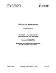
After your order has been processed, you will receive an email with the information
required to register your copy of Isadora. Keep this email in a safe place, as you
will need it to generate future registrations. The information in the email will look
like this:
User Name: Isadora Duncan
Serial Number: ISM-99999
Password: lucky-meter
Registrations Remaining: 3
This key is very important! Please print an offline copy so that you can access it in
an emergency.
Isadora Manual
21
Follow these steps to register your copy of Isadora:
• Ensure you are logged in as the administrator of your computer.
• Run your copy of Isadora by double-clicking its icon.
• Choose Edit > Registration…. The License Agreement will be displayed;
click “Agree” to accept the terms of the license agreement. Then the following
dialog box will appear.
•
•
•
Enter the User Name, Password, and Serial Number, exactly as you received it
in the email from TroikaTronix. (Capitalization counts!)
Click the “Generate Registration Code via Web Page”
Your browser will automatically open and generate a new registration code.
The code will appear near the bottom of the page:
•
•
Using the mouse, select the Registration code and choose Edit > Copy.
Go back to Isadora, and paste the code into the field at the bottom of the
Registration dialog, either by pressing Command-V (MacOS) or Control-V
(Windows), or by clicking the Paste button.
•
After you have correctly entered the registration code, the “Register” button
will become enabled. Click it. Your copy of Isadora is now registered.
Isadora Manual
22
Step 3b: Register – USB Key Version
After you purchase Isadora with a USB Key, you will receive two emails. The first
will contain a temporary registration code that will expire in three weeks or so. This
is to allow you to start working with Isadora until the physical USB key arrives. To
use this temporary code, you must download and install the standard version of the
program. Please see Step 3a for instructions on registering this version of the
program.
The second email will be sent when your USB key is shipped. It will contain the
permanent registration code to be used with the USB key. The key will look
something like this:
C46DFD5684047BD4B3D275D58D6BB689
C4DB260B43DA8A659725C5C455B0F6DF
F83E8350A42B196ECF5DC228DEE385CE
E35E3FDEA81FFC0C048734C2A5FE1BFE
A1756D92665F491E6AF0ACE108E5A5DB
This key is very important! Please print an offline copy so that you can access it in
an emergency.
Once you have received the physical USB Key, follow these steps to register your
copy of Isadora:
• Ensure you are logged in as the administrator of your computer.
• Download and install Isadora as described in Step 1. Ensure that you have
downloaded the special USB Key version of the program.
• Download and install the HASP USB Key drivers. At the time of this writing
the drivers were located on the page at
http://www.aladdin.com/support/hasp/enduser.aspx. If this link doesn’t work
for some reason, search the internet for “hasp driver download” At the time of
this writing, the Macintosh users should install the Sentinel HASP Mac OS X
Run-time GUI Installation. Windows users should install the Sentinel
HASP Run-time GUI Installation. After running this installer, you may be
required to reboot your computer.
• Insert the USB Key into the computer. There is a small red L.E.D. light in the
key; it should illuminate.
• Run the USB key version of copy of Isadora by double-clicking its icon.
• You will see this message when the application starts up:
Isadora Manual
23
•
•
•
Click “OK” to continue.
Choose Edit > Registration…. The License Agreement will be displayed;
click “Agree” to accept the terms of the license agreement. Then the following
dialog box will appear.
Paste the USB registration code you received from TroikaTronix into the text
field within this dialog box.
After you have correctly entered the USB registration code, the “Register”
button will become enabled. Click it. Your copy of Isadora is now registered.
Isadora Manual
24
Tutorials
Preparing Your Computer
Download the Tutorials
Before you begin, you should download the tutorial files from the TroikaTronix
web site. The address is
http://www.troikatronix.com/files/isadora-tutorials.zip
After decompressing this document, you will have an Isadora Tutorials folder, with
six Isadora documents and seven media files.
Online Video Tutorials
You can now go to the Help menu of the Isadora program and find the new Online
Tutorials menu. This will link you directly to 18 Isadora Tutorials. These can also
be found on the TroikaTronix You Tube Channel:
http://www.youtube.com/troikatronix
Basic System Requirements
Here are the basic system requirements needed to run Isadora:
Macintosh Requirements
• MacOS 10.4 or higher
• 1.5 MHz Intel Core Duo or better processor (2 GHz minimum recommended)
• 2 GB of RAM Minimum, 4 GB recommended
Windows Requirements
• Windows XP or higher
• 1.5 MHz Processor or better (2 GHz recommended)
• 2 GB of RAM Minimum, 4 GB recommended
Optional
• Second Video Monitor. Most desktop computers will require a second videooutput card to be installed for them to be able to output video to a second
monitor. Most contemporary laptops support a second video output as a
standard feature. If your laptop does not have this feature built-in, then it is
difficult to add it at a later time.
• Video Digitizing Card or Fire Wire Digital Video Input for live-video capture.
Note that if you want to use your computer’s Fire Wire input to bring live
video into Isadora, you will need to have either a digital video camera with a
Isadora Manual
25
•
Fire Wire output, or a analog video to Fire Wire converter such as the Sony
DVMC-2 or Canopus DVAC-100.
MIDI Interface and MIDI Input/Output Drivers – required if you plan to use
MIDI input and/or output.
Installing MIDI Interface Hardware & Drivers
If you plan on using MIDI as a way of controlling Isadora, or if you need to send
MIDI out of Isadora to control other programs, you will need a hardware MIDI
interface and driver software. The sections below give general information on how
to install the drivers for the various operating systems.
MacOS X
MIDI support is built into MacOS X. You will need to install OS X drivers for your
particular MIDI interface before it will be recognized. These drivers are generally
included on a CD-ROM that accompanies the interface.
Double-click the installer application and follow the instructions provided. You
may need to restart your computer again after installing these drivers – the installer
will ask you to do this if it is necessary. After installation is complete, plug your
MIDI Interface into your computer using the supplied cable.
Once the drivers are installed and the MIDI interface is connected, its input and
output ports should automatically show up in Isadora’s MIDI Setup dialog. (See
next section for information on setting up the MIDI Setup Dialog.)
Windows
MIDI support is built into Windows. You will need to install drivers for your MIDI
interface before it will be recognized. These drivers are generally included on a CDROM that accompanies the interface.
Double-click the installer application and follow the instructions provided. (You
may need to restart your computer again after installing these drivers – the installer
will ask you to do this if it is necessary.) After installation is complete, plug your
MIDI Interface into your computer using the supplied cable.
Once the drivers are installed and the MIDI interface is connected, its input and
output ports should automatically show up in Isadora’s MIDI Setup dialog. (See
next section for information on setting up the MIDI Setup Dialog.)
Setting Isadora Preferences
The first time you run Isadora, you should set up your preferences. To do this you
must find your Isadora application and double click on it. Isadora will open up with
a new file. From the menu along the top of your display choose Edit >
Preferences… to set up your preferences.
Isadora Manual
26
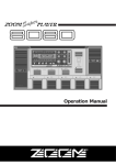
Isadora supports up to six video output channels, called Stages. The Stage section of
the Preferences window allows you to set the display on which a stage will appear
when it is shown.
For now, set up the preferences as follows:
• Click the “Stage” tab at the top of the window to change the Stage settings.
•
Under the heading Stage 1, choose “Screen 2” in the popup menu labeled
Place On. If you have a second monitor output on your computer, the
resolution of the display will be shown in the pop-up menu text (i.e. Screen 2
(640x480)). If not, it will just say “Screen 2”. Make sure that the popup to the
right of the Place On popup in the Stage 1 section is set to “Full” And the
Aspect popup is set to “Match Screen Aspect”.
Isadora Manual
27
•
•
Under the heading Stage 2, Stage 3, Stage 4, Stage 5, and Stage 6, choose
“None” in the popup menu labeled Place On.
Click “OK” to confirm the new preference settings.
This setup will show one stage window on your second monitor output, if a second
monitor output is available. If not, then a smaller window will appear on your main
display.
You can find out more about showing stages, setting them to occupy an entire
display, and other preference settings in the “Preferences” section of the Isadora
Reference chapter of this manual.
Isadora Manual
28
Tutorial 1: Playing a Movie
Creating a New File
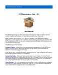
To create a new Isadora file, choose File > New. A new Isadora document that
looks like this will appear:
There are four main areas to the Isadora document: The Toolbox and Toolbox
Filter, found along the left; the Scenes List along the bottom; the Snapshots area
across the top-right, and the Scene Editor, which takes up the rest of the window. A
new Isadora document will have one untitled Scene already inserted into the Scenes
list at the bottom of the window. Note the green bar below that first Scene – this
indicates that the Scene has a Control Panel. (We will discuss control panels in a
later tutorial.)
Scenes are where you create the “program” that defines how the media will be
manipulated and controlled when that scene is active. You may have numerous
Scenes inside of one Isadora document, though, generally speaking, only one Scene
is active at a time. (There is more about multiple scene activation in the Advanced
Topics section of the manual.)
Creating Scenes
To insert a new scene into the Scene List:
• Click to the right of the last scene in the Scene List. If a scene is active, it will
deactivate (go from blue to gray) and a blinking cursor will appear at the spot
where you clicked. This indicates where the new scene will be inserted.
Isadora Manual
29
•
Choose Scenes > Insert Scene.
A new scene called “Untitled-1” will appear where the blinking cursor was
previously. You can see that it has been activated because the Scene Editor will be
visible.
You can activate different scenes by clicking on that scene in the Scene List. To
activate the first scene, simply click on it – you can try this now with the first scene
in the list. It will highlight to indicate that it is active, and the other scene will
deactivate. This will mean more when you have actually inserted some actors into
the two scenes.
To rename your Untitled Scene choose Scenes > Rename Scene and type in your
new scene name. You can find out more about cutting, copying, pasting and
deleting scenes, in the “Scene List” section of the Isadora Reference chapter of this
manual.
Importing Media
Isadora allows you to process both live and prerecorded images and sound. If you
want to use prerecorded media, you will need to import it into Isadora.
Isadora can play and manipulate four types of files: Digital Video Files, Digital
Audio Files (AIFF, WAVE or Sound Designer II), Pictures, Standard MIDI Files or
3D Object Files (3DS).
To import a media file into Isadora:
Choose Windows > Show Media to show the Media Window. It will look like this:
When you create a new Isadora document, it starts with five bins, one for each type
of media file that can be loaded into the window. You can make new bins using the
buttons at the top of the window.
Choose File > Import Media. A file selection dialog will appear. Find the
“dancer.mov” QuickTime movie in the “Isadora Tutorials” folder. The movie will
be imported into Isadora and appear in the Media window as shown below.
Isadora Manual
30
If you like, you can select multiple items in the file selection dialog by holding
down he Shift key as you select multiple items and then click the “Open” button.
All of the files you have selected will be imported into Isadora and appear in the
proper bin in the Media window.
Also note that you can add files by dragging them into the media window from the
Finder (MacOS) or Explorer (Windows).
Note the number to the left of the movie’s name. This number is important, as it is
how you specify which media file to play or manipulate within an actor. Under each
heading, the numbers start at one and count up from there. So, if you have three
movies and three audio files in the Media window, the movies would be numbered
1,2, 3 and the Audio Files would be numbered 1, 2, and 3.
Using Isadora Actors
To define what a Scene does, you drag actors from the Toolbox on the left side of
the window into the Scene Editor and connect them to each other in various ways.
The Toolbox is where Isadora keeps all of the modules that are used to define a
Scene. These modules can be divided into four basic types:
• Actors – Modules that act upon media or information
• Generators – Modules that create media or information
• Watchers – Modules that watch for information to come in from the outside
world
• Senders – Modules that send information to the outside world
The modules contained in the Toolbox are divided into several categories, as seen
in the Toolbox Filter. When you start up Isadora, the group “All Video” will be
selected in the Toolbox Filter, so only video related actors will be seen in the
Toolbox.
To make the modules under a different group available:
• Click on that group’s name in the Toolbox Filter.
Let’s create a scene that plays a movie. To do this:
• Click on the “All Video” in the Toolbox Filter to ensure that all video actors
are visible.
• Click on the scene called “Untitled”. The scene should become selected (if it
wasn’t already) and the empty Scene Editor should be visible in the top-right
portion of the scene.
Isadora Manual
31
•
•
•
•
Click on the module named “Movie Player.” The cursor will change to a plus
sign to indicate that you are about to add a new module.
Move the mouse into the Scene Editor.
Click a second time to deposit the Movie Player actor into the Scene Editor.
The Movie Player actor will appear in the Scene Editor.
Follow the same procedure with the Projector actor (if it is not visible then use
the scroll bar to the right of the list of modules to scroll through the list of
modules). Place it to the right of the Movie Player actor. Your document
should now look something like this:
You need to have both of these modules to play a movie because the movie player
does not send the video image it produces directly to the stage. Instead, you need to
route its video output to one of the stages by connecting it to the Projector module.
The relationship between the Movie Player and Projector actors is the same as that
between a videotape recorder and a television: the former handles the playback of
the video tape, the latter allows you to see those images it produces. You can’t see
the images on the television unless you connect it and the videotape player.
Note that both actors have dots next their input or output property values. These are
the actor’s input and output ports. Input ports are always on the left, output ports
always on the right. You move information (video, audio, or numbers) through
Isadora by linking the output ports of one module to the input ports of another. To
be able to see the video we need to route the video data from the Movie Player to
the Projector actor.
Let’s complete our patch.
Isadora Manual
32
First, connect the “video out” output Movie Player actor to the “video in” input of
the Projector actor. To do this:
• Click on dot to the right of video out output on the Movie Player actor. A red
line will appear and follow the position of your mouse as you move it. (You
don’t have to hold the mouse button down while you do this – a single click
will suffice.)
• Move the mouse to the dot to the left of the video in port on the Projector
actor. The red line will become thicker to let you know that you are inside the
input port.
• While the red line is thick, click to complete the link. Note that at this point
the link between the actors is red, indicating that no data is flowing through it.
Now we need to tell the Movie Player actor which movie to play. Remember, we
imported the movie called “dancer.mov” into the media window previously and it
was number “1” in the list.
• Click in the box to the left of the movie input in the Movie Player actor. The
number will disappear, and the black box will become blue to let you know
that you can type a new value.
• Type the number 1, and then press enter. Once you do this, you will see the
name of the movie (or at least part of it) to the right of the number “1”, e.g.,
“dancer.mov”. That is the movie we previously imported into the Media
Window. Also, the link between the Movie Player and Projector will turn
green, indicating that data is flowing through it. Finally, note the thin yellow
line moving across the green bar along the bottom of the Movie Player actor.
This shows you which frame of the movie is playing currently.
Finally, show the stage:
• Choose Output > Show Stages. The Stage window will appear. (If your
display goes black, it is probably because you forgot to set the Preferences as
described previously. To hide the stage again, hit the shortcut key for Show
Stages (Command-G on MacOS, Control-G on Windows). The stage will
disappear and you will be able to see your document again. Go back to the
section above entitled “Setting Isadora Preferences”, follow the instructions
there, and then try this step again.)
After showing the stage, you should be able to see the movie playing inside of the
stage window. Congratulations, you’ve made your first Isadora scene.
Take note of a few things before you quit this lesson:
• When the movie gets to the end, it automatically jumps back to the beginning
and continues playing from there. By default, the Movie Player actor loops
movies in this way.
• As mentioned above, a link is red when no data is flowing through it, green
when data is flowing through it. This color-coding helps you visualize when
how data moves through an Isadora Scene.
Isadora Manual
33
Tutorial 2: Changing Actor Settings
As you can see, both the Movie Player and the Projector actors have a list of
numbers and titles along both the left and right sides of the modules. The values
along the left side are input properties – they determine what the actor does when its
scene is activated or allow data to flow into the actor. The actor outputs information
through the output properties along its right side.
There are two basic ways to change the setting of a property: either with the
keyboard or the mouse. Let’s start by changing some input property values in the
Movie Player using the keyboard.
• Close any currently open Isadora documents. Then choose File > Open and
locate the file called “Tutorial 2” in the “Isadora Tutorials” folder.
• On your system, it may be that Isadora won’t automatically find the one media
file in this document – dancer.mov. If so, a file selection dialog will appear
that looks like this:
•
The dialog shows you the name of the media file it is trying to locate in the
title of the dialog box, as well in the text just below the file selector area of the
window.
To help Isadora locate the file, select the movie “dancer.mov” in the “Isadora
Tutorials” folder and double-click it.
Make sure that the stage is visible. If it is not, choose Output > Show Stages
to show the stage. You should see a movie of the dancer from Tutorial 1.
Isadora Manual
34
•
•
Then, in the Movie Player actor, click inside the box to the left of the words
play length (the property’s title). The box will turn blue and the number will
disappear to indicate that Isadora is waiting for you to type a value.
Type the number “5” and press enter.
Look at the video output on the stage window. You will see the dancer “jitter”
because we are now looping over a small portion of the movie. The bar at the
bottom of the Movie Player gives a graphic representation of the new setting: the
light green area is now a short portion at the left, while the rest of the bar is dark
green. The light green portion indicates what part of the movie is playing. In this
case, we are playing the first 5% of the movie. Watch the yellow playback indicator
– when it reaches the end of the light green area, it jumps back to the start of the
movie, showing how the movie loops.
• Now, click on the play start property value (the black box.)
• Type “50” and press enter.
The Movie Player is still playing 5% of the movie, but instead of starting at the
beginning, it is starting halfway through the movie, i.e. it starts playing at 50%, and
when it gets to 55%, it jumps back to 50%, etc. Look at the bar at the bottom for a
graphic indication of the portion of the movie that is playing.
You can also change values using the mouse. Currently the speed property value is
set to “1” which means, play forward at normal speed.
• To adjust this property using the mouse, click the speed property value (the
black box to the left of the property title) and, while holding the mouse button
down, drag slowly towards the bottom of the display. You will see the value
get lower as you do.
• Continue dragging down until the speed says “0.5” and then release the mouse
button.
The movie is now playing in slow motion, specifically, at 1/2 of its normal rate.
You can also make the movie play backwards:
• Again click in the speed property value and, while holding the mouse button
down, drag slowly towards the bottom of the display until the value reads “1.0”. Release the mouse button. The movie is now playing at “normal” speed,
but backwards instead of forwards.
Finally, you can make the movie play at twice its normal rate:
• Using the mouse, click in the speed property value and drag up until the value
reads “2”. Release the mouse button.
Another interesting property in the Movie Player is position. Do the following:
• Change play start back to 0
• Change play length to 25
• Change the speed to 0.0
• Using the mouse to change the value, click in the position property value and
drag the mouse up and down. As you movie the mouse you will “scrub” the
Isadora Manual
35
movie back and forth. It is a bit like a DJ scratching a record, but instead you
are scratching video with the mouse movements.
In this last example, each time you change the position property to a new value, the
movie jumps to the specified position within its play duration. The movie doesn’t
continue playing because its speed is set to 0 (i.e. still.)
You can also try editing the other movie properties: try setting the loop enable
property “off” to cause the movie to play only once without looping. Or, import a
movie with a sound track and or change the volume property to change its playback
volume.
Tutorial 3: Interactive Control
In the previous tutorial we used the Movie Player and Projector actor’s to play a
movie on the stage, and you used the mouse and the keyboard to change how the
movie played. In this tutorial we will build on this setup to allow you to
interactively control movie playback with the mouse.
• Close any currently open Isadora documents. Then choose File > Open and
locate the file called “Tutorial 3” in the “Isadora Tutorials” folder, located in
the same folder as your Isadora application.
• Click “Mouse & Keyboard” in the Toolbox Filter to show that group of
actors.
• Drag the Mouse Watcher into the Scene Editor. After depositing it there, take
a look at the horz pos. and vert pos. output property values. These outputs tell
you the horizontal and vertical position of the mouse as a percentage of the
total display size. Move the mouse all the way to the top/left corner of the
display: the outputs will both read 0. Now move the mouse across the top of
the display. You’ll see the horz pos. value gradually increase until it reads
100.Then move the mouse down along the right side of the display. The vert
pos. will gradually increase until it reads 100.
• Set the play length property to 5 by clicking on it and typing from the
computer keyboard. Then, link the Mouse watcher’s horz pos. output port to
the Movie Player’s play start input port. You can see how the horizontal
mouse movements scrub through the movie as it’s playing. Then connect vert
pos. to the play length input port on the Movie Player. You’ll remember from
the previous tutorial that the Movie Player’s play start and play length values
are also expressed as a percentage, from 0 to 100 of the movie’s total duration.
Your patch should look something like this:
Isadora Manual
36
•
Show the stage and experiment by moving the mouse around on the screen.
Try moving the mouse so that it is all the way to the left of the screen, and
nearly all the way to the top. Take a look at the stage: the Movie Player actor
should be looping on a small portion of the movie. Now gradually move the
mouse across the screen to the right. The portion of the movie that is looping
will change as you move. Look also at the indicator at the bottom of the movie
player window to see how it changes as you move the mouse. It will give you
a clear visual indication of what part of the movie you are playing.
This model of taking input from the outside world and linking it to an actor’s input
properties is the one on which all interactive programming in Isadora is based. Just
remember that instead of the mouse position, it could be the computer keyboard,
MIDI, or remote Network connection controlling the previously demonstrated
variations of the play back of the movie. We’ll illustrate these possibilities in later
tutorials, but for now, try a couple of other interactive setups:
• Disconnect the links between the Mouse Watcher and Movie Player. You do
this by clicking on the link to select it (the link changes to a brighter color to
indicate that it is selected) and then choosing Edit > Clear or pressing the
delete or backspace key. Note that you can select more than one link by shift
clicking.
• Set the Movie Player’s speed to 0. Set play start to 0, and play length to 100.
Then connect the Mouse watcher’s horz pos. to the Movie Player actor’s
position input. Move the mouse left and right to “scratch” the movie like a DJ
would scratch a record.
• Now connect the vert pos. to the Projector actor’s zoom input. You will be
able to scratch the video by moving horizontally, and zoom the video by
moving vertically.
• Disconnect all of the links except the one connecting the video out from the
Movie Player to the video in on the Projector. Set the zoom input on the
Projector to 100. Set the Movie Player actor’s speed to “1” again. Set the
Projector actor’s width and height properties to 50. Then connect the
horizontal and vertical mouse positions to the Projector actor’s top and left
Isadora Manual
37
properties. Move the mouse around to squeeze and stretch the video image on
the stage.
You can also use the computer’s keyboard to manipulate actors.
• Disconnect all of the links except the one connecting the video out from the
Movie Player to the video in on the Projector. Set the Movie Player actor’s
speed to “1” again. Set the Projector actor’s width and height properties back
to 100.
• With the Mouse & Keyboard group selected in the Toolbox Filter, click on the
Key Table actor and drag it into the Scene Editor.
• Click on the num. keys property value, type the number 4, and press enter.
The actor will “grow” taller as three more inputs are added.
• Click on the key 1 property value, type ‘a’ (i.e. single-quote, the letter a, and
another single-quote). Then, press the Tab key to move to the key 2 property
value and type ‘s’. Repeat this process for key 3 and key 4, entering ‘d’ and
‘f’ respectively and finish by pressing enter.
• Now connect the key num. output to the Movie Player’s position input.
• Try pressing the a, s, d, and f keys on your computer keyboard. (Make sure
the Caps Lock key is off!) Each time you do, the value at the key num. output
will change to indicate which of the four keys you pressed, 1 through 4. This
causes the movie to jump between 0%, 33%, 66%, and 100% its total play
length. (How does 1 to 4 become 0 to 100? The output value of the Key Table
actor is automatically being scaled to match the range of the Movie Player’s
position input, which can vary between 0 and 100. More on how Isadora
automatically scales values in a later tutorial.)
The key thing here is to see that all Isadora parameters can be manipulated in real
time by sensors (yes, the mouse and keyboard are sensors!) in the real world.
Tutorial 4: Live Video Input
Isadora can just as easily process video from a live input as that from a prerecorded
source. This tutorial shows you how to use live video with Isadora.
First, you must have capture hardware that allows Isadora to “see” the video
coming into your computer. On contemporary Macintoshes the Fire Wire input is
the most ubiquitous way to input video. (Fire Wire, aka iLink or IEEE1484, is also
becoming common on Windows machines.) In addition, there are various capture
boards, PC Cards (for laptops), USB video capture devices, etc. Any of these can be
used with Isadora as long as you have installed drivers that allow them to be seen
by QuickTime. On the Macintosh, this is pretty much a given. On Windows
machines, it is may be somewhat more difficult to configure.
When using capture boards or other external video capture hardware, the
installation procedure varies from vendor to vendor. Follow their instructions to
install the video input hardware on your system.
Isadora Manual
38
Here’s how to create a simple patch that will allow you to show live video on
Isadora’s stage.
• You should start by making sure that Isadora is not running. If it is, quit it
before connecting your camera.
• First, connect your video camera or VCR to the video the video capture device
on your computer. For computers with Fire Wire inputs, you would connect
your digital video camera’s Fire Wire output to the computer’s Fire Wire
input. Most other capture devices accept an analog video input. If this is the
case, connect the analog output of your camera (often a yellow RCA phono
plug) to the analog video input of your capture device.
• Now you need to enable video capture in Isadora – as it is not enabled by
•
•
•
•
default. First, to select the video device from which you will capture, you need
to choose Input > Live Capture Settings. The dialog shown above will
appear.
Ensure that the Channel Select popup menu shows “1”, and that the “Enable”
checkbox is checked.
Click the “Scan for Devices” button. (If you connect your video device after
you start Isadora, it may not be recognized until you click this button.)
Under the heading Video Input, select your capture device/camera from the
popup menu labeled Device. (If your device is not in the menu, then the
device is properly not connected to your computer properly. Check the
connections and power, and click the Scan for Devices” again.)
After selecting your device, click the “Start Live Capture” button. After doing
this, a thumbnail preview of the live video stream should appear above the
box labeled “Channel 1”.
(If you don’t see live video in the Channel 1 box, it probably means that you
are using a capture device with a composite video input, and that the camera is
not connected properly. Ensure that the cable between to your camera iand the
Isadora Manual
39
•
•
capture device is securely attached. Then click the “Stop Live Capture”
button, followed by the “Start Live Capture Button” to try again.)
If you see the video thumbnail, you’ve verified you have live input coming
into Isadora. Then, create a new file by choosing File > New. Drag the Video
In Watcher and Projector actors into the Scene Editor. Then connect the video
out output of the Video In Watcher to the video in input of the Projector actor.
You’re patch should look something like this:
The link between the modules should be green, indicating that video is
flowing from one to the other. Now, choose Output > Show Stages to show
the stage window. You should see the video from your camera or other video
source on the stage.
In subsequent tutorials, we will use a movie as a video source because it is
something that every Isadora user will be able to try. Just remember that “video is
video is video” in Isadora regardless of its source – you can try using live input
instead of prerecorded video in any tutorials where it seems appropriate or
interesting.
Tutorial 5: Real Time Video Processing
Isadora offers a number of video processing actors that can manipulate a video
image in real time. These can be found in the Toolbox if you choose “All Video” in
the Toolbox Filter.
While the function of the video processing actors varies, the basic concept is the
same: video comes into the actor, it manipulates the video image based on
parameters that you set, and sends the result to its video output. Most video
processing actors have just one video input, though some may have two or even
three video sources. We’ll focus on the single source actors in this tutorial.
We’ll start with a simple setup that should illustrate the basic concept.
• As you did in Tutorial 1, insert the Movie Player and Projector actors into the
Scene Editor window, and import the “dancer.mov” file in the “Isadora
Tutorials” folder (located in the same folder as your Isadora application) into
the Media Window.
• Now, click on the Colorizer actor in the Toolbox and drag it into the Scene
Editor. Link the video out port of the Movie Player actor to video in port of
Isadora Manual
40
•
•
the Colorizer actor. Then, connect the video out of the Colorizer actor to the
video in of the Projector actor.
Choose Output > Show Stages to show the stage.
You should see the video image as you did in Tutorial 1. But now, click on the
Colorizer’s red property value and change the setting to –50. The image will
change color. Try other values for the green and blue properties. You can also
click, hold down the mouse and move it up or down to scroll through the
values of these properties.
What’s happening? Well, the red, green, and blue properties control the intensity of
the red, green and blue pixels of the video image. Setting these properties to a
negative value reduces the intensity of that color by the specified percentage, while
setting them to positive values increases them by the specified percentage. If you
were to set the green and blue values to –100, all of the green and blue would be
removed from the image resulting in a red monochromatic image.
Let’s try another actor.
• Select the Colorizer actor by clicking on it, and then delete it by choosing
Edit > Clear or by pressing the delete or backspace keys.
• Now, click on the Dots actor in the Toolbox and drag it out to the Scene
Editor. Connect its video inputs and outputs as you did previously with the
Colorizer actor.
• The video image will look something like a picture printed in a newspaper – a
series of dots that vary in size to represent the brightness of the image.
• Try experimenting with the dot size input property. Larger values produce
larger dots. By the time you get to 25% or so, the image becomes fairly
abstract.
• You can also change the mode property from “circle” to “square”. The latter
produces squares of varying sizes instead of circles.
There are several more actors that manipulate video. One quick way of seeing what
the video processing actors can do is to open the “Isadora Examples.izz” file
located in the “Isadora Examples” folder that was installed with your copy of
Isadora. But, the best thing to do if you really want to understand these modules to
create simple patches of your own. Don’t forget that all of the input property values
can be manipulated in real time – connect the Mouse Watcher’s outputs to some of
the your filter’s inputs and experiment.
Below is a brief description of the single input video processing actors included
with the Isadora, along with a description of what they do so that you can get
started.
• Colorizer – Individual manipulation of the intensity of the red, green, and
blue components of the source video image.
• Desaturate – Allows you to incrementally remove the color information from
the source video.
Isadora Manual
41
•
•
•
•
•
•
•
•
•
•
•
•
•
•
•
•
•
Difference – Compares the brightness of the current frame of video with the
previous frame. The greater the difference in brightness between the two
frames is, the brighter the resulting video. Can produce lovely, ghosting
effects.
Dither – Allows you to make grainier in various ways.
Dots – Manipulates the incoming video so that it resembles a photograph
printed in a newspaper. The dots vary in size to represent the brightness of the
source image. You can vary the size of the dots from quite small to huge.
Flip – Allows you to flip the video image horizontally, vertically, or both.
Freeze – Allows you to freeze the incoming video stream.
Gaussian Blur – Blurs the incoming video stream. Be cautious with the size
parameter – values above 8 can cause Isadora to run very slowly, sometimes
to the point where you might think that it has crashed.
HSL Adjust – Adjusts the hue, saturation, and/or luminance (brightness) of
the video image.
MultiVid – Produces numerous copies of the source video – you can select
the number of copies across and down independently.
Panner– Allows you to pan up and down or left and right within the source
vide stream. It does this by defining an area that is a subset of the source
video, and then moving that area around. The actor gives visual feedback of
what portion of the source video you are seeing.
Shimmer – Produces dust like trails of pixels on moving imagery.
Slit Scan – Copies a single line from the source image and scrolls that out,
either horizontally or vertically. Named after the technique invented by
Douglas Trumbull for the final sequence of 2001: A Space Odyssey. Works
best with slowing moving source imagery.
Spinner – Allows you to rotate and zoom the source image.
The Edge – Edge detection algorithm makes a highly digital look on highcontrast video imagery.
Video Delay – Delays the incoming video image by passing it through a
number of buffers, bucket-brigade style. Useful in a number of scenarios, but
you can start by trying to mix the original and delayed video using the Video
Mixer.
Video Fader – Allows you to fade between the source video image and a
solid color background.
Video Inverter – The default behavior of this actor is to invert the video
image, so that it looks like a photographic negative. For wilder results, change
the “invert color” by using the color picker that appears when you clicking its
‘color’ input’s value box (which shows as a little block of color.)
Warp – As each frame of video comes in, this actor copies one line to the
destination, moving down one line each time. Works best with a stationary
background and a slowly moving object in the foreground. (Try pointing a
camera at your face and moving it slowly.)
Isadora Manual
42
•
Zoomer – Allows you to zoom in or out on the source video stream, with the
additional capability of dimming the image as it passes through the filter. This
can be especially useful with the Luminance Keyer (more on that actor later)
to create beautiful feedback effects.
The most important thing that you can do is to experiment wildly. Our experience
with any software is that the most interesting things occur when you attempt to
misuse it. We encourage you to do the same with Isadora.
Tutorial 6: Sound
Isadora allows you to play and manipulate digital audio files, though in a somewhat
more limited fashion than video. Currently there are two ways to play sound: from a
QuickTime movie or from a digital audio file (AIFF, WAVE, or Sound Designer II
formats.)
Let’s start by importing some media
• Create a new Isadora document. Choose File > Import Media. From the
“Isadora Tutorials” folder import the files called “voice1.aif”, “chords.aif” and
“thunder.mov”. Note that the first two are digital audio files in the AIFF
format, while the second is a QuickTime movie that has audio only– no video.
(You can identify a “sound-only” QuickTime movie in the Media Window
because a speaker icon will replace what would normally be a thumbnail
image.)
First we’ll work with the QuickTime movie audio.
• Click “Video Sources” in the Toolbox Filter. Drag the Movie Player actor into
the Scene Editor.
• Set the movie input property to 1 so that the Movie Player will play the
“thunder.mov” you imported above. You should immediately hear the sound
begin to play. Note that you don’t have to connect the Video Player to any
other modules to hear the sound play. Unlike video, sound within a movie is
sent directly to your computer’s sound output and doesn’t need a Projector
actor for you to hear it.
• Click “Mouse & Keyboard” in the Toolbox Filter and drag the Mouse
Watcher actor from the Toolbox into the Scene Editor. Connect the horz pos.
and vert pos. to the pan and volume inputs of the Movie Player actor. After
doing so, move the mouse around on the screen. When the mouse is towards
the top, the sound is soft, towards the bottom it is louder. Moving the mouse
left and right will pan the sound to the left and right audio outputs on your
computer. (You will only be able to hear the sound panning left and right if
you have stereo speakers built-in or otherwise attached to your computer’s
audio output. Try some headphones if you’d really like to hear the effect.)
• You can also change the play start and play length parameters to play a
portion of the sound. Set the play start to 10 and the play length to 5. You will
Isadora Manual
43
•
hear a short loop of the sound. In fact, all of the movie player properties will
work in the same way as when playing a video QuickTime movie.
Turn off the Movie Player for now by setting is visible property to off.
Now, let’s try the playing the AIFF file.
• Click “Audio” in the Toolbox Filter to display the actors in the Audio Group.
Drag the Sound Player actor into the Scene Editor and set its sound input
property to play the “voice1.aif” file – the number will be 1 or 2, depending
on which number was given to the file when you imported it. Take a look in
the Media Window to be sure.
• The sound does not immediately start playing like the Movie Player. That’s
because you need to trigger its restart input for it to begin playing. Do that
now by clicking in the restart input’s value box with the mouse. (Note that
this is a trigger input, indicated by the dash. You can’t edit the value, but you
can send a trigger when you click in the value edit box.) You should hear the
sound of a solo voice singing a short phrase. Like the Movie Player actor, the
Sound Player has a progress bar along the bottom that shows you how much
of the sound is playing, and a yellow indicator line showing the part of the
sound playing now.
• We can make a simple sampler by adding a watcher to look for keys to be
pressed on the computer keyboard. Click “Mouse & Keyboard” the Toolbox
Filter. Drag the Keyboard Watcher actor into the Scene Editor. This actor
allows you to trigger other actors when a key on the computer keyboard is
pressed.
• Click on the key range input value and type single-quote, the letter a, and then
another single quote, and press enter. The key range value box should read
‘a’. This causes the Key Watcher to look only for the key ‘a’. (Note that it will
not see ‘A’, or a capital a – just a small letter a.) Each time you press ‘a’ on
your computer keyboard, the Keyboard Watcher sends the letter ‘a’ out of the
key output. Connecting the key output to the restart input of the Sound Player
so that you can trigger the sound each time you press ‘a’.
• So now, press the letter “a” on your computer keyboard. Make sure your Caps
Lock key is off so you’re not typing a capital “A”. When you type the letter,
you should hear the sound begin to play. If you press the letter “a” again, the
sound will start playing from the beginning. If you don’t press ‘a’ again, the
sound will play to the end and stop.
• Note that the sound stops playing when it gets to the end. This is because the
loop enable property is turned off. If you change the loop enable property to
“on” and press the letter “a” again, the sound will play continuously.
So, what’s the difference between the Sound Player and Movie Player? The most
important distinction is that Movie Player plays its sounds from your hard drive,
while Sound Player loads all of the sound data into your computer’s RAM (Random
Access Memory – much faster than your disk) when you tell it to play. This means
that Sound Player can make seamless loops, start up instantly, and in general be
more responsive than Movie Player when manipulating the play start and play
Isadora Manual
44
length properties. The downside is that long sound files can consume much of your
available RAM. (FYI: CD Quality Stereo Audio takes up about 10 megabytes per
minute.)
Generally, if you are going to play a music track that is several minutes long, and
you don’t need to manipulate anything besides the volume and pan, you should
convert your sound to a QuickTime movie. If, however, you want to instantly
trigger short samples, or you need to manipulate those sounds using the play
start/play lengths settings, or other settings available only within the Sound Player,
then you should import your sounds as AIFF, wave or Sound Designer II files.
The properties that the Sound Player shares with the Movie Player, namely speed,
volume, pan, play start, play length, and loop enable, work in exactly the same way
for both actors. Sound Player includes two other properties that we will explore
presently: play channel and crossfade.
• To try out the crossfade property, do the following: in the Sound Player actor,
turn loop enable on, set play length to 5. Then connect the Mouse Watcher’s
horz pos. output to the Sound Player’s play start input. Press the letter ‘a’ on
your keyboard to start the sound. Now, as you move the mouse left and right,
the portion of the sound that will play moves through the sound file.
• If you leave the mouse still and listen to the sound, you’ll notice that you often
will get a noticeable click when you reach the end of the play segment and
Sound Player starts playing from the beginning again. Now set the crossfade
property to 5000. This value is specified in samples, so 5000 is about 1/10 of a
second for CD quality sound sampled at 44100 samples per second. The click
should either be gone or much less noticeable. The higher the number, the
longer the crossfade.
To begin our final experiment with Sound Channels, set the loop enable property of
the Sound Player to off so that the sound stops playing. Then disconnect the Mouse
Watcher, and restore the play start/play length values to 0 and 100 respectively.
Then:
• Highlight both the Keyboard Watcher and Sound Player by shift clicking on
them. The choose Edit > Copy and finally Edit > Paste. Drag the copied
actors so that they don’t overlap the originals.
• Working now with the copied actors, set the sound input property of the
Sound Player so that it will play “chords.aif”. Then, change the key range
input property to ‘b’.
• Press the letters ‘a’ and then ‘b’ on your computer keyboard. Each time you
do, ‘a’ should trigger the first Sound Player, and ‘b’ should trigger the second.
Again, this is a bit like a mini-sampler in that you can trigger short portions of
each sound.
• Now, press the letter ‘a’, and before the first sound is done playing, press the
letter ‘b’. Note that the first sound stops playing, and the second one starts.
Why does one sound interrupt the other? It’s because both of the sounds are set to
play on the same Sound Channel. Look at the Play Channel input of the two Sound
Isadora Manual
45
Player actors – both are set to 1. Because a Sound Channel can play only one sound
at a time, when a second one starts to play, it interrupts the first. You can, however,
get both sounds to play by setting them to different sound channels.
Set the play channel of the second Sound Player to 2. Repeat the experiment above,
pressing the letter ‘a’ followed quickly by letter ‘b’. Now you will hear both sounds
playing at the same time.
Being able to interrupt a sound that is currently playing and being able to play two
sounds simultaneously are both useful, depending on what you are trying to do. Just
know that if you have a sound that is cutting out unexpectedly, it’s probably
because you are playing two sounds on the same Sound Channel.
Tutorial 7: Using Scenes
Scenes are a powerful feature of Isadora. They allow you to create several
complicated setups and instantly switch between them, either by manually clicking
on the scenes or by using triggers from the outside world. This is useful when you
are creating pieces with multiple sections that have different interactive setups. In
this tutorial we will illustrate several methods of working with Scenes.
• Close any currently open Isadora documents. Then choose File > Open and
locate the file called “Tutorial 7” in the “Isadora Tutorials” folder, located in
the same folder as your Isadora application.
• Choose Output > Show Stages so that the stage is visible.
• In the Scene List you will see three scenes, label “one”, “two” and “three”.
None of them are active because the default behavior is to start with all scenes
deactivated when opening a file. Activate the scene labeled “one” by clicking
on it.
• After you activate the first scene, you will see its actors appear in the Scene
Editor. You should also see a movie being played in the Stage window.
• Press the space bar. You will see that scene “one” is deactivated, and scene
“two” becomes active, and that the movie appearing in the Stage window
changes.
• Press the space bar again. Now scene “two” is deactivated and scene “three” is
activated. Again the movie shown in the Stage changes.
• Press the space bar one final time. Scene “three” is deactivated and scene
“one” becomes active again.
How does this work? Take a look at the actors in scene “one”. You will see a Movie
Player connected to a Projector Actor. Below that, you will see a Keyboard Watcher
and a new actor we have not yet used called Jump.
The Jump actor has three input properties. The mode works in tandem with the
jump to input to determine which Scene will be activated when the jump is
triggered. When a value arrives at the trigger input, the current scene is deactivated
and the scene specified by the mode and jump to properties is activated.
Isadora Manual
46
If mode is set to relative and the jump to property is set to “+1”, then the Jump actor
will activate the next scene when triggered. If jump to is set to “-1”, then Jump will
activate the previous scene. “+2” would advance two scenes; “-2” would go back
two scenes, etc. Relative jumps are useful when you want to be able to cut and paste
a group of scenes that work together, and have their jumps still work properly.
If mode is set to “absolute”, then the jump to property gives the number of the
scene to jump to, where the first scene in the Isadora document would be “1”, the
second scene would be “2”, etc. These jumps are generally less useful because
cutting and pasting scenes would cause the absolute jumps to activate the wrong
scene. However, there are situations that are useful, for instance, when you always
want to jump to the first scene in the document.
As mentioned above, it is possible to cut, copy and paste, and rename scenes. Here
are some quick examples of how to do this.
• Select scene “two” by clicking on it, and then choose Edit > Cut. Scene
“two” will disappear from the scene list, and you will be left with a blinking
insertion point between scenes “one” and “three”. Note that no scene is
currently active, as both “one” and “three” are not highlighted (i.e. gray).
• Click the mouse to the left of scene “one”. The insertion point will be now be
blinking to the left of scene “one”.
• Choose Edit > Paste. Scene “two” will appear where the insertion point was
previously, and the other two scenes will move to the right.
• Click the mouse in between scenes “two” and “one”. Choose Edit > Paste
again. You will now have another copy of scene “two”.
• With the copy of scene “two” still selected, choose Scenes > Rename Scene.
The name “two” will turn into a text edit box. Type “four” into this scene and
press enter.
• Activate scene “two” (the first scene) by clicking on it. Now press the space
bar three times. Each time you do, the next scene in the list will be activated,
ending up with scene “three”. Press the space bar again. Note that scene
“four” becomes active, because scene “three” jumps backwards two scenes.
Using only the space bar, you wouldn’t be able to get back to the first scene,
which is called “two”. The only way to get there would be to click on it with
the mouse.
You can select a group of scenes by clicking on the first one in the group, and then
shift clicking on the last one in the group. Let’s fix the order of our scenes (so they
go from “one” to “four”) and so that we can go through all of them using only the
space bar.
• Click on scene “three”. Choose Edit > Cut. Click in between scenes “two”
and “four” to show the insertion point there. Choose Edit > Paste.
• Now, click on scene “two”. Then, shift-click on scene “four”. This will select
scenes “two” through “four”. Chose Edit > Cut.
Isadora Manual
47
•
•
•
•
Click to the right of the only remaining scene, labeled “one”. The blinking
cursor will be to the right of scene “one”. Choose Edit > Paste. Our scenes
are now in order. Now we have to fix the Jump actors.
Click on scene “three”. Click in the value box for the Jump actor’s jump to
property, type the number 1, and press enter. Now scene “three” will jump to
scene four when you press the space bar.
Finally, click on scene “four”. Set the Jump actor’s jump to property to –3.
This will jump backwards three scenes, which means we’ll end up at scene
“one”.
Now, press the space bar repeatedly. You’ll see that you are now able to loop
through all the scenes.
Remember, we’re using the Keyboard Watcher as an easy way to illustrate how
input from the outside world can be used to move from scene to scene. If you are
interested in trying out an example that uses MIDI Note On messages to move from
scene to scene, try the tutorial file “Tutorial 7 (Midi)”. If you’d like to try out this
file, quit Isadora, make that your MIDI Drivers are installed and that your MIDI
interface is plugged in. Then start Isadora again and load “Tutorial 7 (Midi)”. Set up
your MIDI Input Ports by choosing Communications > Midi Setup. (See the
tutorial on MIDI for more help.) If you connect a MIDI keyboard to your MIDI
interface and press keys on the keyboard, the Note On messages will do what the
space bar did in the example above.
As a final example, we’ll set up a document that automatically moves from one
scene to another, without any user or performer intervention, as this is often useful
for self-running museum installations.
• Close any currently open Isadora documents by repeatedly choosing File >
Close. Then choose File > New. As usual, you begin with one scene called
“Untitled.”
• Click “Control” in the Toolbox Filter. Drag a Jump actor into the Scene Editor
from the Toolbox.
• Choose the “Generator Group” by clicking on the number 4. Drag the actor
called Pulse Generator into the Scene Editor. This actor will send a trigger at a
regular interval. It has four input properties and one output property. The freq
input allows you to set the frequency of the pulses in pulses per second; the
run property allows you to allow the pulse generator to pause by setting its
value to off; the reset input allows you to start the timing cycle over again.
We’ll only be modifying the freq input here, which you should set to 0.1 Hz.
This means that the trigger output will pulse once every ten seconds.
• Connect the trigger output of the Pulse Generator to the trigger input of the
Jump operator. At this point, even if the Pulse Generator sends a trigger,
nothing will happen because there is only one scene.
• Select the Pulse Generator and Jump actors, and choose Edit > Copy. In the
Scene List, click to the right of the one existing scene, and then choose Scenes
> Insert Scene. Click on the Scene Editor to activate it, and then choose Edit
> Paste to paste the two actors into the scene.
Isadora Manual
48
•
Finally, change the jump to property of the Jump Actor to –1 and then wait.
Then next time the Pulse Generator sends a trigger, you will jump to the first
scene. If you then wait another ten seconds, you will jump to the second
scene. This loop will continue indefinitely.
Of course, we didn’t put any actors in these scenes that show movies or otherwise
manipulate media. But the principal of how to automate the jump process would be
the same regardless of the contents of the Scenes.
Tutorial 8: Fine Tuning Links and Actors
This chapter is vaguely mathematical because of the subject matter. Nevertheless,
for those who dislike things mathematical, I strongly encourage you to take the time
to understand this tutorial because understanding how property values work
together that you can get the most out of Isadora.
Understanding Property Types
Before we talk about scaling values between inputs and outputs, we need to spend a
moment talking about property types. We’ve mentioned some of them in passing in
the previous tutorials: triggers, numbers, video, etc. Basically, each property is of
one of the following types:
Integer
Float
Boolean
Range
Trigger
Video
Sound
Number, without Decimal Points
Number, with Decimal Points
Number, only 0 or 1 (often displayed as off or on)
A pair of integers, specifying a range of values
A Boolean, but specifically looking for a “pulse”
A video stream
An audio stream
All of the numeric types can be connected to one another, and will be scaled and
converted (if needed). Video, however, can only be connected to video, and sound
only connected to sound.
When you link different numeric types, the values may be converted. For instance,
sending a Float value of 1.5 to an Integer input will yield a 1, because Integers don’t
allow numbers after the decimal point. (Note: the part after the decimal is simply
discarded – values are never rounded up or down.) If you send an Integer value of 5
to a Range value, the Range will be set to 5-5 (i.e. from 5 to 5.) Hopefully these
conversions are self-evident, except for the Trigger type, which constitutes a bit of a
special case.
Triggers are numeric values (essentially 0 and 1, displayed as a dash or an X) but
respond to incoming values in a special way. Whenever any new value arrives at a
trigger input, the trigger “fires”. You could illustrate this by linking horz pos.
output of the Mouse Watcher to another actor’s trigger input. Every time you move
the mouse, new values are sent out of the horz pos. output and the trigger input to
which it is connected will fire.
Isadora Manual
49
You can easily find out the type of a property. Just move the mouse cursor over the
property’s value edit box and then don’t move it for a moment. An information box
will appear, that shows you the property’s name, type, and minimum and maximum
values. It looks something like this:
Understanding Value Scaling
When connecting two numeric properties whose ranges of values are the same, you
don’t need to think too much about what happens to the values as they pass through
the link: when a value is sent out of the output, that same value appears at the input
to which it is connected. Even when both properties don’t vary between 0 and 100,
Isadora behaves in a consistent way by scaling the range of output values to match
the range of inputs values. For example, when an output that varies between 0 and
127 (e.g., a MIDI value) is connected to an input that varies between 0 and 100,
Isadora will scale the values proportionally so that as the output goes from 0 to 127,
the input will go from 0 to 100.
Isadora’s default behavior works great when you want an input property to vary
over its entire range. But what if you want a finer degree of control over an effect,
so that a value will vary between 20 and 40 instead of 0 to 100? Or if you need an
input value to go down when the output value driving it goes up? This tutorial
shows you how to accomplish this.
• Close any currently open Isadora documents. Then choose File > Open and
locate the file called “Tutorial 8” in the “Isadora Tutorials” folder, located in
the same folder as your Isadora application.
• This document has three scenes. Click on the Scene called “Tutorial 8”. In it
you will find a Sound Player actor, and a Mouse Watcher with its horz pos.
output connected to the speed input of the Sound Player. Note that the sound
started playing as sound as you clicked on the Scene, even though a Sound
Player normally doesn’t start playing unless you trigger its restart input. In
this scene, we added an “Enter Scene Trigger” actor to start the sound. The
Enter Scene Trigger sends a trigger whenever the Scene it is in is activated.
Thus, activating the Scene starts the sound automatically.
• Now, move the mouse left and right. You will hear the sound go from a low
pitch to a very high pitch, as its playback speed varies from 0 to 10 times
normal speed. Note that Isadora is already scaling the values: as the Mouse
Watcher’s horz pos. varies between 0 and 100, the Sound Player’s speed input
Isadora Manual
50
ranges between 0 and 10. This is Isadora’s default behavior when you link an
input to an output, namely, scale the output value to match the input value.
This particular sound, the recording of the singer we used in Tutorial 6, seems a bit
comical when playing at 10 times normal speed. Let’s limit the range of speed so
that it goes from 0.5 to 1.
• Click on the word speed in the Sound Player. An inspector window appear:
•
•
At the top is the name of the input or output along with the absolute minimum
and maximum values allowed for this property. Below are four value edit
boxes: Ctl Link, Init, Scale Min. and Scale Max.
By changing Scale Min and Scale Max, you can change the minimum and
maximum values of the input, and thus change the way Isadora scales the
values.
Note that these fields work like any value edit box: you can use the mouse to
scroll up or down through the values, or click in the box, type a new value and
press enter.
Click in the value edit box next to “Scale Min.”, type 0.5, and press enter.
Now enter 1.0 into the Scale Max. value edit box.
Move the mouse left and right again. You see (and hear) that, as the horz pos.
output of the Mouse Watcher varies between 0 and 100, the speed of the
sound will go between 0.5 and 1.0.
It is important to know that Scale Min. doesn’t have to be less than Scale Max. In
fact, you can “invert” the scaling by setting the number in Scale Min to a higher
value than Scale Max. Try this:
• Again, click on the word speed in the Sound Player. Now enter 1.0 in the
Scale Min value edit box, and 0.5 into Scale Max.
• Move the mouse from the left side of the screen to the right. Now, the
playback speed of the sound goes from 1.0 to 0.5 as you move from left to
right. You’ve inverted the behavior of the mouse movement.
Initializing Property Values
Finally, we should take a moment here to note the “Init” checkbox and the value
edit box that accompanies it. When you need to make sure that a property is preset
Isadora Manual
51
to a specific value when its Scene is activated, check the “Init” checkbox and enter
the desired value into the value edit box to its right.
Let’s create an example that illustrates why this feature is important.
• Click on the Scene called “Initializing” in the Isadora file “Tutorial 8” you
opened above. Inside is an Envelope Generator that will ramp from 0 to 100
over a period of two seconds. Its output is connected to the volume input of a
Sound Player. There is also a Keyboard Watcher looking for the space bar – it
will trigger a Jump actor to take us to the next Scene. Note that, though the
sound is playing, the current volume of the Sound Player is 0 so you hear
nothing.
• Now, click in the value edit box next to the trigger input property of the
Envelope Generator. You will see the ramp run from 0 to 100. The volume of
the Sound Player is now 100.
• Hit the space bar. You will be in the Scene called “Init Part II”. This scene
looks for the space bar to take you back to the previous scene. Hit the space
bar again.
We return to the Scene called “Initializing”, but unlike last time, we can hear the
sound playing because the value of the volume was 100 when we left the Scene.
Remember, when you leave a Scene, every Isadora value is remembered so that
when you return to the Scene, things will function exactly as they did when you left.
But what if you wanted to make sure that, upon returning to this scene, the sound
always started off with a volume of 0 so that it would be silent until you clicked the
Envelope Generator’s trigger input. That’s where the “Init” value comes in.
• Click on the word volume in the Sound Player. The inspector for that property
will appear. Click the checkbox next to “Init” to check it. Enter the value 0
into the value edit box next to the word Init.
• Again, click the trigger input of the Envelope Generator and then hit the space
bar to go to “Init Part II”. Then hit the space bar again to return to
“Initializing”. You won’t be able to hear the sound, as its volume has been
initialized to 0.
• Now click the trigger input of the Envelope Generator. The sound will fade in,
its volume going from 0 to 100.
Fully understanding how to scale and initialize values as they pass from one actor to
another is the key to getting exactly what you want out of Isadora. Try more
experiments with this feature in your patches to familiarize yourself with this
important feature.
Tutorial 9: More Real Time Video
Processing
In the previous chapter on real time video processing, we only looked at the Video
Processing actors that have one video input and one video output. There are a
Isadora Manual
52
handful of actors that take two or three video inputs. We’ll take a look at several of
them in this tutorial.
Video Mixer
•
•
•
•
Close any currently open Isadora documents. Then choose File > Open and
locate the file called “Tutorial 9” in the “Isadora Tutorials” folder, located in
the same folder as your Isadora application.
Activate the Scene called “Crossfade” by clicking on it. In it you will find two
Movie Player actors, a Projector actor, and an actor we haven’t seen yet called
Video Mixer. A Mouse Watcher is connected to the mix
Choose Output > Show Stages. Note that you won’t see anything yet, as the
input to Projector hasn’t been linked to anything yet.
Move the up and down. As you do, the image on the Stage crossfades from
one video to the other.
The Video Mixer actor fades between two video sources. When its mix amount
property is 0, you see only the video stream arriving at its video in 1 input. As the
value increases, you see more and more of video in 2 until you reach 100, when the
video from that input is all that you see.
Luminance Key
•
•
•
Activate the Scene called “Luminance” by clicking on it. In it you will find
two Movie Player actors, a Projector actor, and an actor we haven’t seen yet
called Luminance Key.
So that you know what imagery you are dealing with, link the video out of the
top Movie Player to the video in of the Projector. You should see a dancer
moving on a black background. Choose Edit > Undo to undo the link. Do the
same with the video out of the bottom Movie Player. You should see some
bubbles floating on a blue background. Again choose Edit > Undo to remove
the link.
Now, connect the video out of the Luminance Key to the video in of the
Projector. What you will see on the Stage is the dancer superimposed on the
bubbles.
What the Luminance Key actor does is combine two images. You specify a range of
brightness in its key top and key bottom properties. Where the foreground video
stream is within this range of brightness, you see the foreground. Where it is outside
this range, you see the background.
Currently the key top is set to 100% and the key bottom to 5%. (100 means as
bright as possible, 0 means black.) The dancer’s body is fairly bright so it falls
within the 100 to 5 range and you see the foreground, i.e. her dancing. But the black
background is outside of the range 100 to 5, so the bubbles show through on that
part of the image.
• Change the key top value to 5 and the key bottom value to 0.
Isadora Manual
53
Now you see a silhouette of the dancer, showing the bubbles inside of that outline.
We’ve reversed the operation: we see the foreground image where that image is
dark and the background image where it is bright.
You can experiment further by connecting the Mouse Watcher’s horz pos. and vert
pos. to the key top and key bottom properties and moving the mouse around the
screen. Note that as you move the mouse around, the graphic in the center of the
Luminance Key actor will give feedback regarding the range of brightness currently
specified by the key top and key bottom properties.
Displace
•
•
•
Activate the Scene called “Displace” by clicking on it. This time you will find
a Movie Player, a Picture Player, a Projector, and yet another actor we haven’t
seen called Displace.
So that you know what imagery you are dealing with, link the video out of the
Movie Player to the video in of the Projector. You should see a dancer moving
on a black background. Choose Edit > Undo to undo the link. Do the same
with the video out of the Picture Player. You should see some bubbles floating
on a blue background. Again choose Edit > Undo to remove the link. Now,
connect the video out of Displace to the video in of the Projector.
You should see the dancer on the black background. Now, use the mouse to
adjust the displace amt property in the Displace actor. As you increase its
value, the dancer’s image will become more and more distorted.
Displace uses the brightness of the video stream at its displace input to shift the
pixels of the video stream arriving at its source input. Where the displace video is
50% gray, the source video’s pixels aren’t moved at all; where it is dark, pixels are
shifted to the left; where it is light, pixels are shifted to the right. How far the pixels
are moved depends on the amount setting.
The angle property determines the angle at which pixels are shifted: when set to
zero, they move left and right, when set to 25% (90 degrees) they move towards the
top-left and bottom-right, etc. The offset parameter will shift the apparent
brightness of the displace video – this is useful if the displace video is too bright or
too dark overall. Experiment with these to see how they change the result.
It is hard to predict what exactly you will get out of Displace, but the results can be
quite beautiful. Import your own movies and try using them with Displace.
Remember, though we used a still picture as our displace source, you can use a
moving video image or live video input just as easily.
Video Feedback
Video Feedback (pointing a video camera at the monitor that was displaying the
image from that camera) was a staple technique of some early video artists. Here
we’ll use a pair of Isadora video processing modules to create our own digital
version of this technique.
Isadora Manual
54
•
•
•
Activate the Scene called “Feedback” by clicking on it. This time you will
find Movie Player, Luminance Key, Zoomer, and Projector actors. Note how
this patch is linked: the dancer video is the foreground input to the Luminance
Key, and the key’s video out goes to the projector. But that same output also
goes to the video in of Zoomer whose output goes to the background input of
the Luminance Key. In essence, we’ve created a loop with the Zoomer actor
manipulating the Luminance Key’s output and feeding it back into itself.
Take a look at the resulting image. You will see a kind of “decay” around the
dancers body as she moves. This decay is because the Zoomer module is
scaling the image down by 1%, making it just a tiny bit smaller. By keying the
original image with a scaled down version of itself, you get these lovely trails.
Experiment with all five parameters of the Zoomer module. You will get a
wide range of effects, from subtle to explosive. Also try adjusting the key top
and key bottom properties of the Luminance Key module.
Tutorial 10: Making Your Own Actors
As you use Isadora, you will find that there are groupings of actors that you often
use. This tutorial shows you how to use Isadora’s User Actors and Macros to build
your own actor from several Isadora actors.
User Actor and Macros work in precisely the same way, except for one: when you
make changes to a User Actor, you have the option of updating every copy (also
known as an instance) of the User Actor so they will all work in exactly the same
way. This is very useful when you’ve have a User Actor in several scenes and you
want the functionality of the other instances to stay in sync. A Macro, on the other
hand, will not update copies of itself when you make changes. You would most
often use a Macro when you simply wanted to logically group some actors or when
you want to save screen “real estate” by embedding several actors into a smaller
object.
In this example, we will focus on creating User Actors. Let’s ay we wanted to turn
two actors (Luminance Key and Zoomer) into our own actor called “Feedbacker”.
• Close any currently open Isadora documents. Then choose File > Open and
locate the file called “Tutorial 10” in the “Isadora Tutorials” folder.
• Click on the Scene called “Feedback” to activate it. (This is the same Scene
we looked at in Tutorial 9.)
• Click “User” in the Toolbox Filter. This is the User Actor Group.
• Bring a User Actor into the current Scene. Initially, the user actor will look
like this
Isadora Manual
55
•
•
•
•
•
•
because it does not yet have any inputs or outputs.
Select the Luminance Key and Zoomer actors and choose Edit > Cut.
Double-click the User Actor. A tab will in the current scene, showing the
name of the User Actor. We will change the name of this user actor in a
moment.
Choose Edit > Paste to paste the Luminance Key and Zoomer actors inside of
the User Actor.
Click “User” in the Toolbox Filter. When you are inside a User Actor’s editor,
the User Group has three more actors available: User Input, User Output, and
User Actor On/Off.
Bring two User Input actors and one User Output actor into the Scene.
Make a link from the first User Input to the video input of the Luminance Key
actor, and the from second to both the horizontal and vertical zoom inputs of
the Zoomer actor. Then connect the User Output to the video output of the
Zoomer actor. The User Actor’s editor now looks like this:
When you link a new User Input or User Output to another actor, two things
will happen: 1) it’s name will automatically change to match the input or
output to which it was connected, and 2) the value associated with the User
Input or User Output will change its type to match the property of the input or
output to which they it connected. This adaptation includes the type, minimum
and maximum, and the scale minimum and scale maximum, etc. In this case,
both two of the actors changed to a type of video because they were connected
to a video input or output. The third actor, connected to the zoom inputs of the
Zoomer, changed to an Integer with a minimum of 0 and a maximum of 1000.
You can change this behavior using the Set User Property Info dialog
described next.
Isadora Manual
56
At this point your using actor is complete. But you many want to rename your User
Inputs and Outputs so that their function is more descriptive. To do this:
• Double-click on the first User Input. The Set Property dialog box will appear.
•
•
•
•
Type “video in” into the Property Name field to give this input a name.
Click OK
Do the same for the User Output, calling it “video out”.
And finally, change the name of the Second User Input to “Zoom”.
Note also the Data Type popup menu. By default, this popup is set to Match
Property, which means that the User Input or Output will adapt to match the
settings of the input or output to which it is connected. If you want to force a User
Input or Output to a particular type, you can select it in this menu. The other
choices are:
•
•
•
•
•
•
Integer: sends/receives an integer number (i.e. no digits after the decimal
point.)
Float: sends/receives a floating point number, i.e. a number that can have
numbers after the decimal point.
Trigger: sends/receives a trigger.
On/Off: sends/receives an integer value that is either on (1) or off (0).
Video: sends/receives video.
Movie/Audio/Picture/MIDI/3D File: sends/receives an integer number that
represents the number of an object in the Media Window. The name of the file
is displayed with the number.
Isadora Manual
57
In this case, we don’t need to change the Data Type of our User Input and Output,
so you can leave it set to Match Property.
To close the editor for your User Actor, choose File > Close. In version 1.3 and
later, following dialog will appear:
Choose “Save & Update All” to save this User Actor. Normally this would update
all other copies of your User Actor to match the changes you’ve just made. In this
tutorial, you have not yet made any copies of this User Actor, so making this choice
has no real effect. But, if there were copies of this actor, either in the document, or
in the Global or Local User Actor toolbox (more on those later), all of these would
be automatically updated to match the changes you’ve just made.
The editor window will close, and you will now see your user actor in the Scene
Editor of the main document.
The final step is to name the User Actor itself.
• Select the actor by clicking on it.
• Choose Actors > Rename Actor. A text edit box will appear above the actor.
• Type “Feedbacker” and press the return key.
Your actor is complete. You can freely copy and paste this actor into other Scenes,
just like any other actor.
Adding Your User Actor to the Toolbox
You can add your User Actor to the Toolbox so that it will be available in other
Isadora documents. This section shows you how.
But, before you can do so, you must choose a folder within which Isadora will save
your User Actors. This is necessary so that Isadora will know where to look for
your custom actors when it is opened. To choose this folder:
• Create a folder on your computer to hold your User Actors. Your
“Documents” folder is a good place to put this, but you could also locate the
folder in the same folder as the Isadora application.
• Choose Actors > Set Global User Actor Folder.
Isadora Manual
58
•
•
Using the file dialog that appears, select your User Actor folder.
Click OK.
Once your User Actor Folder is defined, you can save your new Actor to the
toolbox.
• Select your User Actor by clicking on it.
• Choose Actors > User Actor To Global Toolbox.
Now, whenever you create a start up Isadora, your User Actor will be available in
the toolbox.
Using the Confirm User Actor Edit Dialog (v1.3)
Save & Update All Feature
As mentioned above you are able to able to update all instances of a User Actor
when you finish editing it. To see this in action, try this:
• Click on “User” in the Toolbox Filter. Drag two copies of your newly created
User Actor to the Scene Editor. Set the second input value (which we
connected to the horz and vert zoom inputs of Zoomer) of each User Actor to
two different values.
• Double-click one of the two actors, and change some aspect of it; for example,
change the name of a User Input, move the actors within the Scene Editor, or
edit the value of some input property that is not connected to a User Input.
• Then, choose File > Close. The following dialog will appear:
•
Choose “Save & Update All”
Double-click at the User Actor you didn’t edit. You will see that, inside the actor, it
now exactly matches the modifications you just made. Close this editor, and take a
look at the second input of the User Actor. This value stays the same as it was
previously. When updating User Actors, Isadora attempts to maintain the existing
value of all the inputs to the User Actor if possible. (There are situations where this
can’t be done, e.g., when you change a User Input from a number input to a video
input.)
Now, drag another copy of the User Actor from the toolbox and examine it; you
will see that it also matches the copy you just edited and saved.
The point here is, when you choose “Save & Update All”, you ensure that all
instances of a given User Actor stay in sync and will function in exactly the same
manner.
Isadora Manual
59
Creating a New Instance
Sometimes you want to make a variation of a User Actor that is distinct from the
other instances within your file or the toolbox. In this case, you should choose
“New Instance”. When you do, the User Actor you are editing will be assigned a
new, unique identifier, which makes it distinct from the original User Actor. If you
later edit copies of this variation and choose the “Save & Update All” button, then
only the matching instances of this new instance will be updated; the original User
Actor instances from which you made the variation, will not be changed.
Converting the User Actor to a Macro
If you no longer want this User Actor to update other instances like it, you can
choose the “Convert to Macro” feature. This converts the User Actor into a Macro
that will no longer attempt to update other copies of itself throughout the file or the
toolbox. If you later want to convert this into a User Actor again, you can do so by
selecting the actor and choosing Actors > Convert to User Actor.
Cancel & Revert
If you choose “Cancel” you will be returned to the User Actor editor. If you choose
“Revert”, all of the changes you’ve made since opening this User Actor editor will
be discarded. (You can actually get the changes back, one step at a time, by
choosing Edit > Redo.)
Sharing Your User Actors
If you would like to save a User Actor you’ve made so that you can share it friend,
you can do so by using the Save User Actor command. You can also load another
User’s actor using the Place User Actor command.
To save your actor:
• Click on one User Actor so that it is selected.
• Choose Actors > Save User Actor…
• Use the file dialog that appears to choose a name and a place to save your
actor.
• Click OK.
The actor will be saved to your hard disk with the extension “.iua” which stands for
Isadora User Actor.
Feedbacker.iua
To load an actor you’ve received from someone else:
Isadora Manual
60
•
•
•
•
Choose Actors > Place User Actor…
Use the file dialog that appears to choose the User Actor you want to load.
Click OK.
The User Actor will now be tracking your mouse, as if you had clicked on it
in the Toolbox. Click once to deposit the actor into your scene.
Alternatively, you can just drop the User Actor into your Global User Actors Folder
(described in the previous section). If you do, it will appear in the User Group in the
Toolbox the next time you run Isadora.
Tutorial 11: Getting the Most From the
Projector (v1.3)
•
•
•
•
•
•
•
•
Double click on the Isadora icon to launch the application. This will
automatically open a new “Untitled” file.
Choose Output > Show Stages to show the stage. If the (black) Stage fills the
display, press Command-G (MacOS) or Control-G (Windows) to hide it. Then
choose Output > Force Stage Preview, and again choose Output > Show
Stages to show a smaller version of the stage.
Choose File > Import Media and navigate to the Examples folder included
with the Isadora download.
Select all of the media available in the Examples folder.
Double-click the gray area in the Scene Editor, and from the pop-up toolbox
type “Movie”.
Click “Movie Player” to add a Movie Player actor to the Scene.
Follow the same procedure to add a Projector actor.
Link the video output of the Movie Player to the video input of the Projector.
Your patch should look like this:
Isadora Manual
61
•
•
•
Choose Windows > Show Media to ensure you can see the Media Window.
Look for the movie called “eyezoom.mov” – it will have a number just to the
left. This is the video clips’s media index.
Click on the number “0” just to the left of the word ‘movie’ in the Movie
Player. The number will turn yellow to indicate Isadora is waiting for you to
type.
Type the number “1” (without the quotes) and hit enter. The movie will start
playing. You should now see the movie playing on the Stage
Since V1.0 of Isadora, it has always been possible to position and shape the image
within the frame using the Projector actor. This is accomplished using five
parameters: horz pos, vert pos, width, height, and zoom.
horz pos
and vert pos control where the image appears on the stage, from 0 to
100% of the Stage width and height, respectively. Width and height control how
wide and tall the image is, again from 0 to 100% of the stage width and height.
Zoom controls the size of the image, and can range from 0 (invisible) to 50% (half
Isadora Manual
62
size) to 100% (normal size) all the way up to 1000% (i.e. 10 times the normal
image size.)
Below are some example settings:
Width 50% - Height 100%
Width 100% - Height 50%
horz pos 0% – vert pos 0%
horz pos 0% – vert pos 0%
Zoom 100%
Zoom 100%
Width 100% - Height 100%
Width 100% - Height 100%
horz pos 0% – vert pos 0%
horz pos 25% – vert pos 0%
Zoom 50%
Zoom 50%
Note that when you change the Width and Height parameters, the image will be
squeezed in one direction or another. By changing these parameters you can reshape
the image and change its aspect ratio.
Experiment with these five settings to see how they affect the image. When you are
done, restore the projector to its default values by selecting the Projector actor and
choosing Actors > Reset to Default Values.
Three of the new features have to do with how the image is shaped. They are: spin,
aspect mod, and perspective. Spin does exactly what its name implies: it rotates the
image by a specified number of degrees. Aspect mod allows you to adjust the ratio
of the image’s width to height. Negative numbers reduce the height while positive
numbers reduce the width. Perspective is a bit like the “keystone” control on a
video projector, except that it adjusts the image horizontally instead of vertically. It
is best explained by showing an example: the left image has it’s perspective input
set to –10, while setting it to +10 produces the right image.
Isadora Manual
63
Experiment with these three settings. Restore the projector to its default values by
selecting the Projector actor and choosing Actors > Reset to Default Values when
you are done.
In Isadora 1.1 it became possible to display two or more images on the same stage
by using multiple Projector actors in the same scene. To take best advantage of this
capability, it is essential to understand the blend, intensity, and layer input
properties.
The layer input property controls the layering of the images. Higher numbers are
closer to you; lower numbers are further away. So, if you have two Projector actors,
in the same scene, and layer input of the first one is set to 5, and the layer of the
second is set to 4, then the image from the second projector will be drawn behind
that of the first.
There are three blend modes: additive, transparent and opaque. Additive means that
the two images are literally “added together” – they will both be visible at the same
time, even when one is on top of the other. When using this setting, the intensity
parameter simply controls the brightness of the image. Transparent means that the
transparency of the image can be adjusted using the intensity parameter. If intensity
is set to 100, then the image will be opaque, and you won’t be able to see the image
behind it. As the intensity approaches zero, the image will become more and more
transparent, allowing you to “see through” to the images below. The opaque blend
mode means the image’s rectangle is always opaque. So, as the intensity approaches
zero, you will see a black rectangle on top of any images rendered behind it.
Isadora Manual
64
Optimizing for Speed
There are many factors that influence Isadora’s video processing speed, including
the speed and type of your processor, amount of RAM installed on your computer,
hard disk speed, the format in which the video files are stored, and several other
factors. This section details several tips to help you get the very fastest frame rates
from Isadora.
Tip 1: When it comes to speed, the three most important hardware
considerations are the CPU, Graphics Card (GPU) and the Hard Drive.
CPU
It is always the case that higher CPU frequencies are better. At this time, a dualcore 2 GHz processor would be the minimum one would want to consider for
serious work when working with higher resolution video. Multiple core machines
can also boost performance.
When using the standard movie players and video processing actors and FreeFrame
1.0 effects, the video processing is done by the CPU. In this case, CPU speed is the
top consideration when it comes to speed.
Graphics Card (GPU)
The importance of the graphics card will depend on the version of Isadora you are
using. As mentioned above, if you are not using the Core Image actors provided
with the optional Core Image upgrade, then CPU speed is the key factor one must
consider. In this case, spending a lot of money on a top-grade graphics card will not
boot performance appreciably.
However, when using the Core Image version of Isadora, the speed of the graphics
card, its available RAM, and the transfer rate from main system memory become
far more important. If you are using this optional feature, investing in a high-grade
graphics card can improve performance measurably.
Hard Drives
When it comes to hard drives, the fastest units are the relatively new SSD (solidstate) hard drives. Because there is no physical head to move, access speeds, are
phenomenally fast. especially when playing more than one movie. Such speed can
be especially important if you are attempting to play multiple HD clips. The
downside is that these drives are very expensive as of this writing.
Second in speed would be eSata drives, third would be FireWire 800, and finally
USB 2. We do not recommend USB 2 when playing high-resolution movie clips
from an external drive. When considering traditional drives, a drive with a high
RPM speed will improve performance. Drives with 10,000 are now available, with
7200 RPM being a the recommended minimum.
Isadora Manual
65
The standard drives included with most laptops are usually 5400 RPM which will
give less efficient performance, but are still workable depending on the resolution
of your video.
Tip 2: Add as much RAM (Random Access Memory) to your computer
as you can afford.
Modern operating systems rely on a feature called “virtual memory.” When the
computer senses that some data that resides in your computers RAM (i.e. the
extremely fast internal memory linked to your main processor) has not been used
for a while, it will write it out to disk to make more RAM available to other
applications. This is called “page swapping” and can adversely affect performance.
The best way to solve this problem is to add more RAM to your computer. As a
general rule, 2 Gigabytes is a good base line. 4 Gigabytes is even better. Page
swapping will often take place on machines with less memory than 2 Gigabytes of
memory.
Tip 3: Donʼt run other applications at the same time as Isadora
Every running application consumes system resources. So, especially when using
Isadora for a live performance, don’t run any other applications at the same time.
Even if they aren’t “doing anything” they get some of the processor’s time, and thus
slow down Isadora.
Tip 4: Keep your video resolution as low as you can.
The biggest burden any real-time video software faces is the size of the image it has
to process. This data has to be brought in from the hard drive or from a live camera
input, moved through any effects, and sent to the graphics card for output. It’s a
simple relationship: as resolution increases, the speed at which those frames can be
processed decreases.
In addition, there is the CPU overhead necessitated by decoding the video from it’s
compressed format to the uncompressed format that can be processed by the video
effects and/or graphics card.
So, while Isadora has no limitation on the resolution of the video it can play, if you
want good frame rates, it is best to keep the resolution as low as you possible so as
to get the best frame rates.
To give you a sense of the amount of data being processed, take a look at this table:
Resolution
Megabytes / Frame
Megabytes / Sec. @
30FPS
320x240 QVGA
0.3 Mb
9.2 Mb/S
720x480 DV Video
1.3 Mb
41 Mb/S
1920x1080 HD
8.2 Mb
248 Mb/S
Isadora Manual
66
Thus you can expect a single frame of full res 1080p video to take 26 times longer
to process than a QVGA frame and six times longer than a frame of DV. Moreover,
consider the situation when you’re cross fading from one scene to the next: if you
were playing two 1080p HD clips, you’d be pushing around nearly 500 Mb per
second. That’s approximately 62% of the maximum bus bandwidth of a top-of-theline 2011 Mac Book Pro. Playing a third HD clip would put you at 93% of the
maximum bus bandwidth of the same machine.
Note that the final column in the table above is the decompressed bandwidth of the
image; the actual bandwidth required when reading the clip from disk can be
considerably lower depending on the compression scheme used.
BONUS TIP: If you are outputting to video projector with less than HD resolution
(e.g., 1024x768) there is no reason to play a full res 1080p HD video. Recompress
or crop the so that it matches the resolution of your output device.
BONUS TIP: If you are letterboxing 16:9 video into a 4:3 output device (e.g.,
1024x768) calculate the resolution you are actually using. For example, on a
1024x768 device, the resolution of a 16:9 image that uses the entire width of the
display would be 1024 x 576. (used height = display width * 9 ÷ 16) Using a movie
rendered at 1024x576 saves you 25% of the full 1024x768 bandwidth.
Tip 5: Keep all video resolution consistent
When Isadora has to combine two video streams of different resolutions (e.g., with
the Video Mixer actor), it has to scale one stream to match the resolution of the
other. (Which one gets scaled is determined by the “Video Image Processing”
section of the Video tab in the Preferences.) Scaling is slow, and so you want to
avoid it as much as possible. If all of the video streams you are processing are the
same resolution, you will get the best possible performance.
Tip 6: In addition to changing the resolution of your files, choosing the
correct codec for recompression is crucial (Photo JPEG, H264, DV,
NTSC)
Photo JPEG
Photo JPEG is ideal for 320 x 240 (QVGA) or 640x480 (VGA) resolution, it offers
speed improvements when playing video from your hard drive and while the files
will not be as small as with other codecs, the Photo JPEG compressor offers several
advantages. The most important is that it requires less processor power to
decompress the images when compared to many other codecs.
When compressing using Photo JPEG, we suggest using a quality setting of “high”
or “medium” (75% or 50%). Using a quality setting of “best” produces very large
files that are not significantly better in image quality.
Isadora Manual
67
DV NTSC or DV PAL
For standard DV resolution, PAL is best for 720 x 576 and NTSC is best for 720 x
480. The NTSC and PAL DV codecs exhibit many of the same benefits as Photo
JPEG, and are relatively efficient to decompress.
High Definition (HD)
For HD resolution the HDV codec has performed best in our tests, though it is
anamorphic (i.e., it’s true resolution is 1440x1080, not 1920x1080.) This codec
requires about 3 Mb/s in disk bandwidth, which is relatively low. For the highest
HD quality we recommend Apple ProRes. The color fidelity and image quality is
excellent but it also requires a significantly higher disk bandwidth of 20 Mb/S.
H264 should not your first choice!
The H264 is extremely popular because it makes small files with good image
quality. But it is not the best choice to use with Isadora (or any interactive video
software) for several reasons.
First, the CPU overhead required to decompress the image is significantly higher
than for Photo JPEG or DV NTSC/PAL.
Second, H264 is only designed to play forward. If you are a VJ or artist who is
scrubbing video or you often use the position input of the Movie Player actors, then
H264 is most definitely not for you. If you play an H264 movie backward, or you
scrub the video back and forth rapidly, you will see the CPU usage increase
significantly. This is simply because the codec is not designed to deliver the images
in reverse order.
By contrast, the Photo JPEG and DV formats render each frame individually (i.e.,
the current image is not inherently related to the previous one.) Therefore it these
codecs are very fast when jumping to an arbitrary location within the clip and will
play just as well backwards as forwards.
You can use a number of software tools to recompress your files, but perhaps
easiest is the Pro edition of Apple’s QuickTime Player. See Tip 9 for instructions on
how to use QuickTime Player to compress your video.
Tip 7: The duration of a movie has little or no impact upon
performance.
We often are asked: “Can Isadora play movies that are an hour long?” The answer
is “yes,” because, in fact, the duration of a clip has little to do with playback
performance.
The video playback software within the operating system only reads a small amount
of the video file at a time, usually about a half-second in advance of where the
current playback position. Thus, whether a clip is 1 or 1000 minutes long has little
impact on performance. Far more important are the factors listed in the tips listed
above.
Isadora Manual
68
Tip 8: Stick with one frame rate for all your videos.
Isadora will happily play videos of any frame rate within the same file. But for the
smoothest playback performance, you should use the same frame rate for all your
videos and set the Target Frame Rate in the General tab of the Isadora Preferences
to the same rate.
Furthermore, you should set the Refresh rate of your monitor or video projector to a
multiple of your chosen frame rate if at all possible. (Consult the manual for your
monitor or projector to learn how to do this.)
For NTSC video rendered at 29.97fps:
§
Set the Target Frame Rate to 29.97 fps
§
Set the Monitor/Video Projector refresh rate to 60 Hz.
For PAL/SECAM video rendered at 25fps:
§
Set the Target Frame Rate to 25 fps
§
Set the Monitor/Video Projector refresh rate to 50 Hz.
For videos transferred from film at 24fps or 23.978 fps:
§
Set the Target Frame Rate to 24 fps or 23.978 as appropriate.
§
Set the Monitor/Video Projector refresh rate to 50 Hz.
Tip 9: Turn off the Video Capture when youʼre not using it.
The Capture Control actor allows you to turn live video on and off from within an
Isadora scene. If you are not using live video in a section of your piece, then use
this actor to turn it on and off at the appropriate moment.
Tip 10: How to use Appleʼs QuickTime Player (Pro Edition) to
recompress your movies.
Below are instructions on how to use the Apple’s QuickTime Player to store your
movies in this format.
NOTE: While QuickTime and QuickTime Player are free, the Pro edition required
to recompress movies costs $29.99 at the time of this writing. You must have the
Pro Edition to recompress movies using QuickTime Player.
1) Open QuickTime Player by double clicking on its icon. From the File menu select “Open
Movie” to open the movie you want to recompress.
2) Choose File->Export or press cmd-E to call up the export dialog.
3) After the window appears, click the Options button to show the “Movie Settings”
window.
4) Then click the Settings button.
5) Choose your desired compression format using the pop-up menu under the heading
“Compressor”.
Isadora Manual
69
6) Set the slider under “Quality” to the halfway point, which should be labeled “Medium.”
You can use “High” if you like – you’re movies will be somewhat larger but the quality
of the image will be better.
7) In the text box to the right of “Frame Rate” type 30, if it is not already set to 30. (Use 25
if you are compressing PAL movies.) Uncheck the other two boxes that say Key Frame
and Limit Data Rate.
8) Press the OK button.
9) You’re back at the Movie Settings window. Click on the Size button.
10) Click the “Use Custom Size” radio button. Two text boxes marked Width and Height
will appear.
11) Type your desired sizes into the Width and Height text box.
12) Press the OK button.
13) You’re back at the Movie Settings window. Press the OK button.
14) Choose a name for your movie (it should be different than the old name) and press the
Save button.
15) This process can take a while, depending on how long your movie is. A progress dialog
(a window with a little blue thermometer type display) will appear to show how things
are going.
16) When the progress dialog disappears, your movie is done.
17) Open the new movie and play it to see how it looks now.
To see the difference in size between the original movie and the newly compressed
one, do the following:
1) Bring the original movie to the front by clicking on its window.
2) Choose Movie->Get Info to show a window that gives information about the
movie.
3) Choose “Movie” from the pop-up menu on the top left.
4) Choose “General” from the pop-up menu on the top right.
5) Look at the “Data Size” and “Data Rate” in that window. Take note of the
values.
6) Close the window by clicking on its close box in the top left or by choosing
File->Close.
7) Now bring the new movie to the front by clicking on its window.
8) Follow the same procedure starting at Step 2 to show its Data Size and Data
Rate.
9) You’ll see how much smaller the movie is and how its data rate has been
lowered through the resizing and compression process.
Isadora Manual
70
Isadora Reference
Importing & Managing Media
Media Window Basics
Isadora allows you play and manipulate movies, audio files, pictures, Standard
MIDI Files, and 3D Object Meshes in the 3DS (3D Studio Max) format. To use
these files, you must create references to them in the Media Window.
The Media Window can contain any number of bins, each of which is associated
with a particular media type. Each bin can contain any number of media files. You
can organize your files by creating new bins and dragging existing media references
into them.
When you do import media, Isadora automatically places the media files in the first
available bin of the matching type in the Media Window, i.e. movie files go into the
first movie bin, sound files go into the first sound bin, etc.
It is important to understand that the Isadora document does not contain the actual
media file data – just a pointer to its location on your hard drive or other storage
device. If you later delete the file, Isadora won’t be able to find it. It is a good idea
to create a folder to hold your Isadora document and all of the media associated
with it. This should make it easier to manage your data when you are working with
many files.
Isadora can import and play several types of movie, sound, and picture file formats.,
namely:
Video Files
QuickTime Movies (.mov)
Digital Video Files
Shockwave Files (.swf)
Sound Files
Audio Interchange Format Files (.aif, .aiff)
Windows Wave (.wav, .wave)
Sound Designer II (.sd2)
MIDI Files
Standard MIDI Files (.mid)
Pictures
Macintosh Pictures (.pic)
QuickTime Image (.qtif)
Windows Bitmap (.bmp)
Photoshop Documents (.psd)
Isadora Manual
71
TIFF (.tif)
Graphics Interchange Format (.gif)
PNG (.png)
SGI Image Files (.sgi)
Mac Paint (PNTG)
Targa Image Files (TPIC)
3D Object Meshes
3D Studio Max (.3ds)
Importing Media
To import one or more media references using a File Selector dialog:
• Choose Windows > Show Media to show the Media Window. Initially, it
will look like this:
•
•
•
Choose File > Import Media…. A file selection dialog will appear.
Or, control-click (MacOS) or right-click (Windows) to show a pop up menu.
From that menu, choose “Import Media…”.
Select the file you want to open by clicking on it, and then click Open. If you
like, you may shift-click to select several files (they can be of different types)
and then click Open.
To import one or more media references using Drag and Drop:
• Select the file or files you want to import in the Finder (MacOS) or in from
the Explorer (Windows).
• Drag the files over the Media Window. Its outline will highlight to indicate
that it is ready to receive files. If the group of files you have selected contain a
file type that Isadora cannot read (i.e. not a Movie, Sound File, MIDI file, or
Picture) then no highlighting will appear.
• Release the mouse button to import the files.
All of the files you have selected will be imported into Isadora and appear as
reference in the Media Window. The references will be stored in the first available
bin of that matches the type of file you dragged.
Here is how the media window looked after we dragged in three movies, one sound
file, and seven pictures and one 3D model:
Isadora Manual
72
Note the number to the left of the each media reference. This number is used to
identify the media when specifying which one you want to play inside an actor.
To replace the file associated with a media reference:
• Double-click the media reference (it is OK if the reference is currently
<Unassigned>).
• Or, control-click (MacOS) or right-click (Windows) the media reference to
choose “Replace Media…” from a pop-up menu.
• A file dialog will appear that allows you to select a different file to associate
with that media reference.
• Select the new file and click Open to confirm the new file. The name of the
reference in the Media Window will change to match that of the newly
selected file.
Selecting Media References
To select an item or bin:
• Click on a media reference to select it. Clicking on a bin selects the bin and all
media references inside that bin.
To select multiple media references
• Click on an unselected media reference to select it. Then hold down the shift
key and click another item to select all items in between.
• Or, Click on an unselected media reference and drag to select several
contiguous items.
• You can hold down the Command/Apple key (MacOS) or the Alt key
(Windows) and click a media reference to toggle its selection state.
Isadora Manual
73
To select an multiple bins
• Click on an unselected bin to select it. (All media references within that bin
will be selected too.) Then hold down the shift key and click another bin to
select all items and bins in between.
• Or, Click on an unselected bin and drag to select several contiguous bins.
• You can hold down the Command/Apple key (MacOS) or the Alt key
(Windows) and click a bin to toggle its selection state.
Managing Media
To add a new bin to the Media Window
• Click on the appropriate button at the top of the Media Window.
Add Movie Bin
Button
Add Sound Bin
Button
Add Picture Bin
Button
Add Midi Bin
Button
Add 3D Bin
Button
• A new bin of the specified type will be added to the end of the Media Window.
Automatically Adjusting Media Numbers
When you delete or move a media object, the number of the media objects will
change, and Scenes that reference a given media object will not play the same file
they played before the change. Often this is the behavior you want, but it may be
that you want to ensure that all the actors still play the same media after you have
deleted or moved some object in the Media Window. To do this, you need to enable
the “Auto Adjust Media” feature in the Media Window.
Auto Adjust
Media Enabled
Auto Adjust
Media Disabled
To enable or disable the Auto Adjust Media feature:
• To turn on the Auto Adjust Media feature, click the button in the top left of
the Media Window.
• To turn off the feature, click the button again.
To delete a media reference or bin:
• Select the media references you want to clear.
• Choose Edit > Cut to remove the references from the Media Window. Or,
control-click (MacOS) or right-click (Windows) the media reference to
choose “Cut” from a pop-up menu.
To clear (unassign) a media reference:
• Select the media references you want to clear.
Isadora Manual
74
•
•
Choose Edit > Clear to clear the references from the Media Window. Or,
control-click (MacOS) or right-click (Windows) the media reference to
choose “Clear” from a pop-up menu.
After a reference is cleared, its title will read “<Unassigned>”. Attempting to
play a media reference that has been unassigned has no effect – the media
simply doesn’t play.
To hide the media references within a bin:
• Click on the downward pointing arrow to the left of the bin’s title. The items
within the bin will be hidden.
To show the media references within a bin:
• Click on the sideways pointing arrow to the left of the bin’s title. The items
within the bin will be shown.
To reorder media references within a bin, or to move them to a different bin:
• Select the media references you want to move. You should only select media
references of the same type (i.e. only movies, only audio files, etc.)
• Click a second time on one of the selected items and drag the media
references. As you do, an insertion point will appear between pairs of existing
media references or below an existing bin. This let’s you know where the
media references will be inserted when you release the mouse.
• Release the mouse button when the insertion point indicates the desired
position of the media references. When you do, they will be moved to that
position.
QuickTime movies and the High Quality Flag
Since version 1.1, Isadora has respected the high-quality flag setting for each
movie. This flag is most important for movies that contain interlaced video (notable
DV-NTSC and DV-PAL). When the high-quality is turned on, both fields of the
video are rendered; when turned off, only one field will be rendered, and the other
field will be interpolated. You can set the high-quality flag for a movie using
QuickTime Player Pro or other applications.
In the Media Window, you can set a flag to force Isadora to render the movie at
either high-quality or standard quality. Setting either of these flags overrides the
high-quality flag stored with the movie.
To force high-quality playback of your movies:
• Select the movies references you want to play in high-quality mode.
• Click the HQ button at the top right of the Media Window. An HQ marker
will appear to the right of each movie in that was selected.
• Or, you can right-click (or control-click on Mac OS) and choose Set Force
High Quality from the popup menu.
Isadora Manual
75
To force standard-quality playback of your movies:
• Select the movies references you want to play in standard-quality mode.
• Click the SQ button at the top right of the Media Window. An SQ marker will
appear to the right of each movie in that was selected.
• Or, you can right-click (or control-click on Mac OS) and choose Set Force
Standard Quality from the popup menu.
Using the Scene List
An Isadora document can have any number of Scenes, each of which is a collection
of actors that manipulates one or more streams of digital media. Isadora scenes are
like scenes in a play: each one may have a different set, different lighting, etc.
Similarly, each Isadora Scene may manipulate media in a completely different way.
Because you can jump almost instantly from one scene to another using the Jump
actor or by clicking on Scenes in the Scene List, it is possible to move from one
interactive setup to another as you move through sections of a performance.
When you manually activate a Scene in the Scene List by clicking on it with the
mouse, its actors are displayed in the Scene Editor and they all begin
communicating with each other. If the activated Scene generates video output, it
will appear on the appropriate Stage, if it produces sound, the sound will be sent to
the computer’s audio output, etc.
It is important to understand that each Scene is completely independent from the
other Scenes in the same document. Because of this you cannot pass data from one
Scene to another. When you activate a new scene, all of the media output of the
previously active scene stops.
Generally speaking, only one scene is active at a time. However, you can use the
Activate Scene and Deactivate Scene actors to activate more than one scene at a
time. See the documentation for these two actors for more information.
Each Scene is visually represented by rectangular shaped objects displayed in the
Scene List at the bottom of an Isadora document.
Each Scene is associated with a Control Panel, indicated by the bar just below the
Scene proper. (When the bar goes between two or more scenes, it indicates that
those Scenes share the same Control Panel.) Control Panels allow you to create a
user interface for your Scene consisting of one or more Isadora controls. See the
section “Using Control Panels” on Page 104 for more information.
Isadora Manual
76
Activating & Deactivating Scenes
To activate a Scene manually:
• Click on the Scene you want to activate, which means that that Scene will be
selected. The highlighting on the previously activated scene (if there was one)
will be removed, the Scene you clicked on will be highlighted, the actors for
the selected Scene will appear in the Scene Editor, and they will begin
communicating with each other and the outside world.
To deactivate the currently active Scene, leaving no Scenes active:
• Click on the background area of the Scene List. If there was a scene activated,
its highlighting will be removed and its actors will disappear from the Scene
Editor indicating that no Scene is active currently. This will stop all output
(video, sound, MIDI) that was being generated by the Scene that has been
deactivated.
Selecting Scenes
To select a Scene:
• Click on the Scene you want to select, which means that that Scene will be
activated. The highlighting on the previously activated scene (if there was
one) will be removed, the Scene you clicked on will be highlighted, and the
actors for the selected Scene will appear in the Scene Editor.
To select a range of scenes:
• Click on the first scene in the group you want to cut or copy. It will highlight
to indicate that it is selected.
• Shift-click on the last scene in the group you want to select. Isadora will
highlight the second scene you clicked, and all of the scenes in between. Note
that the Scene Editor will disappear, because you cannot have more than one
scene active at a time.
To make a discontinuous selection, or to deselect one or more selected scenes:
• Hold down the Command () key (MacOS) or Alt key (Windows) and click on
the scenes that you want to select. If it was not selected previously, it will be
selected. If it was selected previously, it will be deselected.
Adding and Removing Scenes
To insert a new scene into the Scene List:
• Click to the left of the first scene, to the right of the last scene, or in between
two scenes. A blinking cursor will appear at the spot where you clicked. This
indicates where the new scene will be inserted.
Isadora Manual
77
•
Choose Scenes > Insert Scene. A new scene will appear where the blinking
cursor was previously. You can see that it has been activated because the new
scene will be highlighted and the Scene Editor will be visible.
To activate a scene:
• Click on the scene you want to activate. It will highlight to indicate that it is
selected, the Scene Editor will be shown (if it isn’t already visible) and all of
the modules in that scene will be visible inside the Scene Editor.
Note that you can activate a new scene from within a Scene by using the “Jump”
actor.
To cut or copy a range of scenes:
• Select one or more scenes.
• Choose Edit > Cut. Isadora will cut the selected scenes.
To paste scenes:
• Click to the left of the first scene, to the right of the last scene, or in between
two scenes. A blinking cursor will appear at the spot where you clicked. This
indicates where the scenes will be pasted.
• Choose Edit > Paste. Isadora will insert scenes that you cut or copied
previously at the point where the cursor was blinking.
To delete scenes:
• Select one or more scenes.
• Choose Edit > Clear or press the Delete key. Isadora will delete the selected
scenes.
Reordering Scenes
To change the order of the Scenes in the Scene List:
• Select one or more scenes.
• Click in one of the selected Scenes and hold the mouse button down for a
moment. (This delay is to prevent you from accidentally dragging scenes.)
• The cursor will change into a “closed hand” icon
• Drag the scenes to the right or the left.
• As you drag, the scenes will reorder themselves so you can see the order.
•
When you have placed the scenes where you want them, release the mouse
button..
Isadora Manual
78
Renaming Scenes
To change the name of a scene:
• Highlight the scene whose name you want to change. Then choose Scenes >
Rename Scene. A text edit box will appear in place of the scene.
• Type the new name of the scene and press enter. The text edit box will
disappear and the scene will be displayed with its new name.
• Shortcut: Control-clicking (MacOS) or right clicking (Windows) will show a
popup menu. From that menu choose “Rename Scene” to open the text edit
box for a Scene’s name.
Changing the Width of a Scene
Sometimes it is useful to change the width of a scene to better visually organize
your Isadora document.
To change the width of a scene:
• Hold down the Command Key (MacOS) or the Control Key (Windows) and
place the cursor at the right edge of the Scene you wish to modify. The cursor
will change to indicate you are ready to change the width of the scene.
•
Drag the mouse left or right to adjust the size of the scene.
Editing Scenes and Using Actors
As described in the previous chapter, a Scene is a collection of actors that
manipulates one or more streams of digital media. So, the Scene Editor is where
you define the way in which those actors work together.
Using the Scene Editor, you place your actors and connect the outputs of one to the
inputs of the other. In so doing, you define the how the media (whether it is video,
sound, MIDI, etc.) is manipulated. You will also edit the property values associated
with each actor here, allowing you to determine the specific way in which a given
actor functions. Finally, you will edit how data is scaled as it moves through a link.
Most Scenes follow this model: a media stream arrives from a source, whether it be
prerecorded media stored in the Media Window or media arriving in real time from
the outside world; the media stream flows through one or more actors to change it
in some way, and then the manipulated data is sent to an appropriate output.
Interactive setups have an added component in that some information from the
Isadora Manual
79
outside world is changing the way in which one or more actors manipulate their
media streams in real time.
To understand what each of the actors do, take a look at the Tutorials or read the
Isadora Actors Reference portion of this manual. This section describes how to add,
remove, organize and connect actors within a Scene.
Adding New Actors to a Scene / Using the Toolbox
The actors available in Isadora can be found in the Toolbox,
which is located along the left side of an Isadora document.
Near the top of the window is the Toolbox Filter, as seen
here on the right. It gives several categories into which
Isadora’s actors have been grouped.
To make a actors from one group visible in the Toolbox:
• Click on the name of the group you wish to show in
the Toolbox Filter. The name will highlight and only
the actors in that group will appear in the Toolbox.
To hide or show the Toolbox Filter:
• Click the white “disclosure triangle”
just above
and to the left of the Toolbox Filter. Or choose
“Toolbox Filter” in the Views menu.
To quickly locate an actor by name: (v1.3)
•
•
•
Click in the textbox at the top of the toolbox and type any portion of the actors
name. Any actor, from any of the eight groups, whose name contains the text
you type will appear in the toolbox.
You may also choose Actors > Search for Actor or Command-Shift-A
(MacOS) or Control-Shift-A (Windows) to activate the search text box. (This
feature added in v1.3)
To clear the search text box, click the small “X” to the right of the text field.
To add a new actor into a Scene:
• Click in actor you want to add in the Toolbox. The cursor will change into a
plus sign to let you know you have selected an actor.
• Move the mouse into the Scene Editor. As you do, you will see the actor you
selected following the movements of your mouse.
• Once you have the actor in the position you desire, click the mouse to confirm
its addition to the Scene.
• Note: You can click again the Toolbox or hit the Escape (esc) key to cancel
the addition of the actor.
Isadora Manual
80
To add a new actor into a Scene using the “Popup” Toolbox (v1.3)
• You can access a “popup” version of the Toolbox at any time by doubleclicking in the grey area of the Scene Editor.
•
•
•
After the Popup Toolbox appears, type all or part of the name in the text box
at the top of the Popup Toolbox. Only actors with that text in their name will
be displayed.
Then, either click the desired actor with your mouse or use the up or down
arrow keys to select the desired actor and press the enter or return key on your
keyboard.
The Popup Toolbox will disappear and the desired actor will be deposited into
the scene.
Selecting and Deleting Actors
To select an actor:
• Click on the main portion of the actor with the mouse.
To select multiple actors:
• Hold down the shift key while clicking on the actors you want to select.
To select a group of actors:
• Click on the Scene Editor’s background, and drag the mouse. A selection
rectangle will appear. When you release the mouse, any actors under the
selection rectangle will be selected.
• If you hold down the shift key before you click, the actors under the selection
rectangle will be added to the current selection.
Organizing Actors
To reposition actors within the Scene Editor:
• Select one or more actors.
Isadora Manual
81
•
Click on the main body of the actor and drag. The selected actors will follow
the movements of your mouse until you release the mouse button.
Editing Actors
To delete actors:
• Select one or more actors.
• Choose Edit > Clear or press the Delete key. Isadora will delete the selected
actors.
To cut or copy a range of actors:
• Select one or more actors.
• Choose Edit > Cut. Isadora will cut the selected actors, or
• Choose Edit > Copy. Isadora will copy the selected actors.
• Note that when cutting or copying a group of actors, all of the links between
actors in the group will be kept intact. When you paste these actors, the links
that were in place at the time of the cut/copy will be restored.
To paste actors:
• Make sure that the Scene Editor is active by clicking on its background.
• Choose Edit > Paste. Isadora will paste the actors that you cut or copied
previously.
• The newly pasted actors will all be selected, so you can click on any one of
them and drag to move them to a new location.
Making Links Between Actors
For Isadora’s actors to work together, you must define the way in which the data
moves from one actor to another. You do this by making links between the output
of one actor and the input of another.
Property Types
Each property is of one of the following types:
Integer
Float
Boolean
Range
Text
Trigger
Video
Sound
Blobl
Isadora Manual
Number, without a decimal points
Number, with decimal points
Number, only 0 or 1 (often displayed as off or on)
A pair of integers, specifying a range of values
A string of text characters.
Number, only 0 or 1 represented as a hyphen (–) and an X.
Whenever a new value arrives, the trigger “pulses”.
A video stream
An audio stream
Blob information from an Eyes++ module.
82
You can find out the type of a property by placing the mouse cursor over a
property’s value edit box and then keeping it still for a moment. An information box
will appear that shows the property’s name, type, and its minimum and maximum
values.
You can connect any numeric or trigger output to any other numeric or trigger
input. Video outputs can only be connected to video inputs, sound outputs to sound
inputs.
To connect one actor’s output to another actor’s input:
• Click in an output port (the blue dot on the right side of an actor). A red line,
representing the link, will now follow the movements of your mouse.
• Move to another actor’s input port (the blue dot on the left side of an actor).
The link will thicken whenever you are inside of a valid input port.
• Click the mouse to confirm the link.
• Some data types are incompatible and so you will not be allowed to make a
connection. (For instance, you cannot connect a video output to a numeric
input.) If the data types are incompatible, the cursor will change be into a
circle-slash icon ( ) to indicate you are not allowed to make a connection.
• Note that the link is red when no data is flowing through the link, and that it is
green when data is flowing.
To cancel a link in progress:
• Hit the esc key, or press Command-Period (MacOS) or Control-Period
(Windows).
• Or, control-click (MacOS) or right-click (Windows) to choose “Cancel Link”
from a popup menu.
To delete a link:
• Click on a link to select it. It will turn bright red or bright green (depending on
whether or not there is data flowing through the link) to indicate that it has
been selected. You can shift click to select more than one link at a time.
• Choose Edit > Clear to delete the link or press the delete key.
Isadora Manual
83
To segment Links for better visual organization:
You may want to organize your links visually so that you can better understand
what your Scenes are doing when it contains several actors. You can do so by
laying them out in segments. For example:
To create a link with segments:
• Start the process as before by clicking in an output port. The link will begin
tracking your movements.
• As appropriate, click on the Scene Editor background. When you do, a new
point will be added to the link. The red line now tracks from that point.
• Continue adding segments as desired. To finish the link, click in the input port
of the target actor.
To move an existing Link segment:
• Click in the link segment and drag. Horizontal segments can only be dragged
up and down. Vertical segments can only be dragged horizontally.
Mutable Inputs and Outputs
Normally, one cannot link inputs and outputs whose data types do not match. For
instance, a video output cannot normally be connected to a number input because
such a connection would have no meaning.
But, some actors support “mutable” inputs or outputs – meaning these inputs or
outputs will “mutate” (i.e., change) to match the data type when the first link is
made to them. Mutable inputs or outputs are indicated by a green dot next to the
input or output port. (Normally this dot is blue.)
For example, take a look at the Table actor:
Table Actor with Mutable Connections
The image on the left shows the actor before any connections have been made. The
green dots at the three value inputs and the val out output indicate that these ports
Isadora Manual
84
are mutable. When you add a new Table actor, the default data type for the inputs
and outputs is float (i.e., a number with a decimal point). In the second image, a
video actor has been connected to the first input. All the inputs and outputs of the
Table actor have changed to say video, indicating they can receive or send a video
stream. In addition, the dots next to the inputs and outputs have become blue to
because they are no longer mutable. In this example, once you’ve made the first
link and the data type changes to video, you would not be able to make a new link
to a numeric input or output until you disconnected all of the links to the value and
val out ports.
Many actors who have mutable inputs or outputs are like the Table actor; once a
connection is made to any input or output, the data type of all related inputs or
outputs changes to match the first connection and these ports are no longer mutable.
There are some exceptions though. Consider the Send Serial actor:
Send Serial Actor Connected to Multiple Types
In this actor, each input is individually mutable. The first input was attached to a
Toggle actor whose output shows on/off; the second input was connected to the
output of a video effect. In both cases, the input “mutated” to match the data type of
the first link. The dots to the left of these two inputs are blue to indicate they are no
longer mutable. But the dot to the left of the third input, which has not yet been
connected, is green to indicate that it can still mutate.
Getting Help for an Actor
Each actor has built in help information. To display help for an actor, control-click
(MacOS) or right-click (Windows) and choose “Actor Help…” from the popup
menu. If you control or right click in an input or output, you can choose “Actor
Input Help…” or “Actor Output Help…” to see specific information about that
input or output.
To get help for an actor:
• Control-click (MacOS) or right-click (Windows) and choose “Actor Help…”
from the popup menu. A small window will appear with the help information.
Click anywhere to dismiss the help window.
Isadora Manual
85
To get help for an actor’s property:
• Control-click (MacOS) or right-click (Windows) and choose “Actor Input
Help…” or “Actor Output Help…” from the popup menu. A small window
will appear with the help information. Click anywhere to dismiss the help
window.
As a shortcut, you can also option click (MacOS) or alt click (Windows) an actor or
its properties to show built in help information.
Navigating Inside the Scene Editor
In addition to using the scroll bars, you can use the mouse to drag the visible area of
the Scene Editor up and down or left and right.
To scroll up or down, or left and right using the mouse:
• Hold down the command key (MacOS) or alt key (Windows) and click in the
gray portion of the Scene Editor. The cursor will change into a “hand”. While
holding the mouse button down, drag the Scene Editor.
Scaling Values Between Outputs and Inputs
Whenever you link an actor’s numeric output to another actor’s numeric input,
Isadora’s default behavior is to scale the output’s range of values so that they match
the input’s range of values.
Two pairs of values are used to calculate how values are scaled. Output properties
have a Limit Minimum and Limit Maximum value that give the lowest and highest
possible values that can be sent by that output property. Input properties have a
Scale Minimum and Scale Maximum value that specifies the range to which any
value arriving at that input will be scaled.
By changing these values for any pair of connected output and input properties, you
can control the way that values are scaled as they move from output to input.
Here is an example:
Isadora Manual
86
Outpu
Limit Maximum: 10
Inpu
Maximum: 10
Scale Maximum: 6
Scale Minimum: 2
Minimum:
Minimum:
AsLimit
the output
property value on the left goes from 0 to
100, the input value will go
from its Scale Minimum and Scale Maximum values, which have been set to 20 and
60 respectively. Thus, when the output property sends a value of 50 (halfway
between 0 and 100) the value at the input will “see” the scaled of 40 (halfway
between 20 and 60). You can also invert this relationship (e.g., Scale Minimum is
60 and Scale Maximum is 20) so that as the output value goes up, the input value
will go down.
Whenever you add a new actor to a Scene, each input property’s Scale Minimum
and Scale Maximum values default to the absolute minimum and maximum value
allowed by that property. Similarly, each output property’s Limit Minimum and
Limit Maximum also default to the absolute minimum and maximum.
To change the scaling of an input property:
• Click on the name of an input property, found just to the right of the input
value box on the left side of an actor. The name will turn yellow to indicate
that it is selected and an inspector with information about that property will
appear.
At the top is the name of the input along with the absolute minimum and
maximum values allowed for this property. Below are four value edit boxes:
Isadora Manual
87
•
Ctl Link, Init, Scale Min. and Scale Max. (We’ll discuss the “Init” box
below, and the “Ctl Link” boxes in the section on Controls.)
The values of “Scale Min.” and “Scale Max” determine the range of values to
which any incoming value will be scaled.
Change Scale Minimum and Scale Maximum values to specify the range of
values to which values arriving at this input will be scaled. These value edit
boxes work like the ones inside any actor – you can use the mouse to scroll
through the possible values, or you can enter a value into the box by clicking
on it, typing the value, and pressing enter or return.
To specify the limits of an output property:
• Click on the name of an output property, found just to the left of the output
value box on the left right of an actor. The name will turn yellow to indicate
that it is selected and information about that property will appear just below
the Scene Editor.
•
•
•
At the top is the name of the output along with the absolute minimum and
maximum values allowed for this property. Below are three value edit boxes:
Ctl Link, Scale Min. and Scale Max. (We’ll discuss the “Ctl Link” value in
the section on Controls.)
The values of “Limit Min.” and “Limit Max” determine the minimum and
maximum values that the output will send, and are used in combination with
the Scale Minimum and Scale Maximum input property values to determine
how values will be scaled from an output to an input.
Change Limit Minimum and Limit Maximum values to specify the lower and
upper limit of values that can be sent by this property. These value edit boxes
work like the ones inside of any actor – you can use the mouse to scroll
through the possible values, or you can enter a value into the box by clicking
on it, typing the value, and pressing enter or return.
To invert the relationship between and output and an input:
• If you want to invert the relationship between the output and the input so that
as the output goes up the input goes down, set Scale Minimum to a value
greater than Scale Maximum.
Isadora Manual
88
For example, if the output property ranges from 0 to 100, and its is connected
to an input whose Scale Minimum is 100 and Scale Maximum is 0, then as the
output property goes from 0 to 100 the input will go from 100 to 0.
Presetting a Property Value
There are situations when you may need to preset a property’s value when its
actor’s Scene is activated. This is accomplished using the “Init” checkbox and
value.
To mark a property value to be preset when its Scene is activated:
• Click on the name of an input property, found just to the right of the input
value box on the left side of an actor. The name will turn yellow to indicate
that it is selected and an inspector with information about that property will
appear.
•
•
At the top is the name of the input along with the absolute minimum and
maximum values allowed for this property.
Click in the checkbox to the left of the word “Init” to enable initialization.
Then enter the value to which the property will be initialized in the value edit
box to the right.
Editing Property Values
To change the value of one of the actor’s properties, do one of the following:
• Click on the value edit box (the black box next to the property’s name) and
drag the mouse up or down. The value will go up or down as you drag the
mouse.
• Click in the value edit box. It will turn blue and the current value will
disappear to indicate that you are about to type a value. Type the new value,
and press enter.
Note that if the value you are editing is displayed as text (e.g., the wave type
property of the Wave Generator, which can be set to sine, square, triangle,
etc.) you can type the first few letters of the text and press enter. Isadora will
find the value that most closely matches what you typed and enter it for you.
(It is possible that this feature may not be implemented on some third-party
Isadora Manual
89
•
actors – if this is the case, you can always type a number, usually starting
with 1 for the first item, to select the correct value.)
Click in the input port (the blue dot) of a value. A combination slider/value
edit box control will appear. You can edit the property’s value by moving the
slider’s indicator up or down, or by typing into the value edit box. This feature
is especially useful if you’ve collapsed the actor, as it is the only way you can
change the value without first expanding the actor.
Collapsing/Expanding Actors
Each actor has three main components: the body (the rectangle on which the other
elements sit), property value boxes, and the property value names. The latter two
can be shown or hidden independently, allowing you to make an actor much
smaller. Here is how the Note On Watcher actor looks in all of its possible states:
Standard
Property Names Hidden
Values Hidden
Collapsed
To make one or more actors as small as possible:
• Select the actors you wish to collapse.
• Choose Actors > Collapse. Isadora will hide both the value edit boxes and
property titles, making the actor as small as possible.
To restore one or more actors to its standard state:
• Select the actors you wish to restore.
• Choose Actors > Expand. Isadora will show both the value edit boxes and
property titles, returning the actor to its normal state.
Isadora Manual
90
You may also hide or show the value edit boxes independently.
• To hide the value edit boxes of the currently selected actors, Choose Actors >
Hide Values. Isadora will hide the value edit boxes of the selected actors.
Choose Actors > Show Values to make the value edit boxes visible again.
• To hide the property titles of the currently selected actors, Choose Actors >
Hide Names. Isadora will hide the property titles of the selected actors.
Choose Actors > Show Names to make the property names visible again.
You can still edit any actor’s input property value, even when its value edit boxes
and property titles are no longer visible.
To see the title of a property when its actor is collapsed:
• Move the mouse over the input or output port (the blue dot.) The property’s
name will be displayed next to the mouse cursor:
To edit the value of an input property when its value edit boxes are not visible:
• Click in the input port of an actor. A combination slider/value edit box will
appear, like this:
•
You can edit the property’s value by either dragging the slider indicator (the
white triangle), clicking on the relevant input port and using the scroll on your
mouse for more precise control, or, by clicking in the value edit box and
typing a new value.
•
If adjusting values for Actors with properties that do not have a scale
min/max:
•
You can edit the property’s value by either dragging the wheel, clicking on the
input port and using the scroll on your mouse for more precise control, or, by
clicking in the value edit box and typing a new value.
Isadora Manual
91
•
To adjust the color input of an actor, click on the color input port and select
your color. Please note that to dismiss the color picker icon, click in the scene.
When opened again the picker will have saved your last choice in the small
square row below (the previous color selected in the example was black as can
be seen by the black square).
To show or hide all actor names in a Scene:
• If the names are currently visible, choose Actors > Hide Names to hide them.
• If the names are currently hidden, choose Actors > Show Names to show
them.
User Actors & Macros: Creating Your Own
Actors
As you use Isadora, you will find that there are groups of actors that you often use
together. Isadora’s User Actors and Macros allow you to build your own actors
from one or more Isadora actors.
User Actor and Macros work in precisely the same way, except for one: when you
make changes to a User Actor, you have the option of updating every copy (also
known as an instance) of the User Actor so they will all work in exactly the same
way. This is very useful when you’ve have a User Actor in several scenes and you
want the functionality of the other instances to stay in sync. A Macro, on the other
hand, will not update copies of itself when you make changes. You would most
often use a Macro when you simply wanted to logically group some actors or when
you want to save screen “real estate” by embedding several actors into a smaller
object.
Once you have identified a group of actors that you want to encapsulate into a User
Actor or Macro, you can create one as follows: click “User” in the Toolbox Filter,
drag the User Actor or Macro actor into the Scene Editor.
You then open its User Actor Editor tab by double clicking on it. The tabs look like
this:
Isadora Manual
92
Inside the editor, you can add the Isadora actors that define the function of this
particular User Actor. Finally, you will add User Inputs and/or Outputs to bring data
into, and send data out of, the new actor. When the actor is complete, close its tab
by clicking its close box and choose “Save & Update All” in the Confirm User
Actor Edit dialog. (No dialog will appear for Macros, as they do not update copies
of themselves.) The user actor now exists in your Scene, and can be copied, pasted
and otherwise treated like any other Isadora actor.
Once a User Actor or Macro has been created, you can open its editor tab at any
time and change its functionality without disturbing the way in which the owning
Scene operates. Additionally for User Actors, you have the option of updating all
other instances of this actor to match the changes you’ve just made, or to create a
new, unique instance of the actor that is distinct from the previous versions.
User Actors are an advanced feature - you may want to review the User Actor
tutorial in the Tutorials section to fully understand how they work.
User Actor Synchronization Feature (v1.3)
As of version 1.3, you are able to automatically synchronize all copies of a given
User Actor after you’ve made changes to it. This allows you to easily ensure the
functionality a given User Actor is the same throughout an Isadora document.
Whenever a new User Actor is created, it is assigned a unique identifier. Each User
Actor with the same identifier is called an instance, in other words, a kind of
“copy” of the master User Actor. This identifier is maintained for all instances of
the User Actor, whether it is created by copying and pasting, or by dragging it into
the Scene Editor from the Toolbox. Whenever you make a change to one instance
of a given User Actor, you are given the opportunity to automatically update all
instances (i.e. all copies with the same unique identifier) throughout document and
in the toolboxes so that they match the newly edited version. Any existing links into
or out of the User Actor are maintained, as long as the corresponding User Input or
Output was not deleted, and if the types are compatible. (If you change a User Input
or Output from a number type to a video type, for instance, the link will be broken
because these types are not compatible.)
Isadora Manual
93
When you close a User Actor editor tab, you are presented with a dialog that allows
you to choose if you’d like to update all matching copies to reflect the recent
changes, or to create a new instance of the actor.
The meaning of each of the choices is described below.
Save & Update All
Updates all instances of this User Actor (including any copies in the Global or
Local User Actor Toolbox) so that they exactly match the changes you’ve just
made.
New Instance
Create a new instance of this User Actor that is distinct from all previous instances.
Existing instances are left unchanged.
Convert to Macro
The User Actor is assigned a new, unique identifier and is marked as being a
Macro. This actor will no longer preset the “Confirm User Actor Edit” dialog or
attempt to update other copies of itself throughout the file or the toolbox.
Cancel & Revert
You may also choose “Cancel”, which will return you to the User Actor editor. If
you choose “Revert”, all of the changes you’ve made since opening this User Actor
editor will be discarded. (You can actually get the changes back, one step at a time,
by choosing Edit > Redo.)
Further details regarding all of these choices can be found in the section below
entitled Saving the User Actor after an Edit.
Considerations for User Actors Created Before v1.3
User Actors created prior to version 1.3 of Isadora do not have the unique identifier
that allows the automatic User Actor synchronization described above. In essence,
User Actors created before 1.3 function as what are now called Macros; when you
close the editor for a pre v1.3 User Actor, you will notice that no dialog box will
appear asking if you’d like to “Save & Update All”, etc. This is because Isadora
cannot identify which User Actors are instances of the User Actor you’ve just
edited. In other words, you can continue to use and edit pre-v1.3 User Actors as you
did in previous versions of the program.
Isadora Manual
94
But, you may want to update the User Actors in your document to make the new
features available. To do this, simply select the User Actor and choose Actors >
Update User Actor to New Format.
No Recursive References Allowed
Because pre v1.3 User Actors did not offer the “Save & Update All” feature, you
were allowed to recursively reference those actors, i.e. a copy of a given User Actor
could be placed inside itself. This is no longer allowed in v1.3 and later, because it
would lead to an infinite loop when attempting to update the actors.
If you attempt to double-click a pre v1.3 User Actor that contains embedded
references to itself, you will see the following dialog.
If you choose “Cancel”, the User Actor Editor will not be opened. If you choose
“Update” the embedded User Actors will be converted to the new format and
assigned a new, unique identifier to ensure they are distinct from the “parent” User
Actor.
User Actors Files Before and After v1.3
Prior to version 1.3, Isadora User Actors files were saved with the extension “iza”.
The extension for 1.3 and later User Actors is “iua” (Isadora User Actor). Isadora
will continue to load Global User Actors in the Global User Actor Folder with the
“iza” extension. You can also use the “Place…” command to add “iza” files to your
document. But all newly created User Actor files will have the extension “iua” to
indicate that they are saved in the new format.
Creating and Editing a User Actor
To add a User Actor:
• Click “User” in the Toolbox Filter. Then, select the User actor by clicking on
it, drag it into the Scene, and click again to deposit it. You will see an actor
with no inputs and no outputs.
Isadora Manual
95
To edit a User Actor:
• To open a User Actor’s editor tab, double-click the User Actor. A new tab will
appear at the top of the Scene editor, displaying the name of your User Actor.
In this editor you add Isadora actors, as well as User Input and User Output
actors to define the functionality of your actor.
Adding Isadora Actors to a User Actor:
• To add an Isadora actor into a User Actor, click on the actor in the User Actor
Editor’s Toolbox, and deposit it into the User Actor’s editor.
Creating and Editing User Inputs and Outputs
Adding inputs or outputs to a User Actor:
• Click on “User” in the Toolbox Filter. There you will find the User Input and
User Output actors.
• Drag a User Input and/or User Output to the Scene Editor and deposit it by
clicking. They will look like this initially:
•
•
After adding a User Input or User Output actor inside of the User Actor
Editor, a corresponding input or output will appear as part of the User Actor
that you are modifying.
Important Note: At the moment you connect a User Input or User Output to
another actor, all of the properties of the User Input or Output mutate to match
the properties of the actor to which it was connected. This includes the
Property Type (integer, float, video, etc.), Minimum and Maximum values,
and the Scale Min/Max or Limit Min/Max values.
Setting input and output properties:
• Double-click the User Input or User Output actor. A dialog box will appear
that allows you to define its characteristics:
•
Set the name of this property, as it will appear in your User Actor, by typing
the name into the “Property Name” text edit box.
Isadora Manual
96
•
•
Set the data type using the “Data Type” pop-up menu. There are five
possibilities:
1. Match Property
2. Integer – Whole numbers with no decimal point
3. Float – Numbers with a decimal point
4. Trigger – A trigger input
5. On/Off – An on or off (1 or 0) only input
6. Video – A video stream
7. Movie – A movie file number from the Media Window
8. Audio File – An audio file number from the Media Window
9. Picture File – A picture file number from the Media Window
10. MIDI File – A MIDI File number from the Media Window
11. 3D File – A 3D File number from the Media Window
The most common setting is Match Property. When this option is selected, the
User Input or Output will automatically adapt itself to match the
characteristics of the input or output property to which it is connected. (E.g., if
you have a User Input, and you change the Scale Min or Scale Max of the
property to which it is connected, the User Input’s Scale Min and Scale Max
will automatically be updated to match the new settings.)
When you choose Integer or Float you can set the absolute minimum and
maximum values for this property using the “Minimum Value” and
“Maximum Value” fields. (Note: to use the lowest possible value for the
selected Data Type, type MIN into the Minimum Value field. To specify the
highest possible value, type MAX into the Maximum Value field.)
Like inputs and outputs on normal Isadora actors, the Minimum and
Maximum Value fields determine the absolute minimum and maximum value
that can be received by this input, or that can be sent out of this output.
However, like any input or output, these limitations can be further constrained
by using the inspector window to change the Scale Minimum, Scale
Maximum, Limit Minimum and Limit Maximum values as needed.
Click the OK button to confirm your settings.
User Input/Output Reordering (v1.3)
As of version 1.3, you can easily reorder the inputs and outputs of a User Actor.
To reorder the inputs or outputs of a User Actor:
• Click the small button labeled “I/O” (i.e., input/output) in the current tab.
• A dialog box will appear listing all the inputs and outputs, each in their own
column:
Isadora Manual
97
•
•
•
Click on an input or an output in the list.
Drag it to the desired position.
Click OK.
Saving the User Actor After an Edit (v1.3)
After you’ve edited a User Actor and you choose File > Close, you will be
presented with the following dialog box:
The five choices have the following meanings:
• Save & Update All: All instances of the User Actor you have just edited will
be updated to reflect the changes you just made. This includes all User Actors
in all currently open Isadora documents, as well as all instances in the Global
or Local Actor Toolboxes.
Any existing links into or out of the User Actor are preserved, as long as the
corresponding User Input or Output was not deleted and if the types are
compatible. (If you change a User Input or Output from a number type to a
video type, for instance, all corresponding links will be broken.)
Isadora also attempts to preserve the input values for the other instances, even
though the internal structure of the actor will be updated to exactly match your
recent edits. This behavior recognizes that not every input to a User Actor will
be driven by some output value; sometimes the inputs are just edited
manually, and such values should be preserved In some cases the input value
Isadora Manual
98
•
•
•
•
cannot be maintained; for instance, when a numeric input type is changed to a
text input type, the value cannot be preserved because the types are
incompatible. Another case is when the range of a User Input was changed
inside the User Actor; in this case, the old value is limited to the current
possible values.
New Instance: Choosing this option assigns a new unique identifier to this
User Actor, making it distinct from any existing copies. Choose this option if
you intend to make a variation of the User Actor and do not want to change
the functionality or layout of other matching actors in the open documents or
in the Global or Local Actor Toolboxes.
Convert to Macro: Choosing this option assigns a new, unique identifier and
is marked as being a Macro. This means that when you make changes to this
actor, it will no longer attempt to update other copies of itself throughout the
file or the toolbox. If you later want to convert this into a User Actor again,
you can do so by selecting the actor and choosing Actors > Convert to User
Actor.
Cancel: The editor window is not closed, and nothing is updated.
Revert: If you choose “Revert”, all of the changes you’ve made since opening
this User Actor editor will be discarded. (You can actually get the changes
back, one step at a time, by choosing Edit > Redo.)
Note that if you are editing a User Actor saved prior to v1.3, this dialog box will not
appear. This is because the User Actor does not have the unique identifier required
to allow the automatic synchronization of User Actor instances. You can convert
this User Actor to the new format by saving it to the Global User Actor toolbox.
Converting a Macro to a User Actor (v1.3)
You can choose to convert a Macro to a User Actor at any time. If you choose to do
this, the actor will be assigned a new, unique identifier and marked as a User Actor.
If you later edit this actor or copies of it, you will be presented with the “Confirm
User Actor Edit” dialog as you would with any User Actor.
Converting a User Actor to Macro:
• Select the Actor
• Choose Actors > Convert Macro to User Actor.
Adding User Actors to the Toolbox
If you create a User Actor that you would like to use frequently, you can add it to
the Global Toolbox. After you do so, the actor will appear in the User section of the
Toolbox even after you quit and restart Isadora. You can drag this actor into the
Scene Editor like you would any other.
You may also add an actor to the Local Toolbox. In this case, the user actor is
stored along with your Isadora document. This feature may be useful if you create
user actors that would only be needed within a particular file.
Isadora Manual
99
Choosing a Folder to Hold Your Global User Actors:
Before you can store any actors to the Global Toolbox, you must choose a folder to
which they will be saved. This is the folder that Isadora will look in to find your
user actors the next time it is started up.
• Choose Actors > Set Global User Actor Folder. A dialog will appear that
allows you to select a folder.
• Click OK to confirm your selection.
To Add a User Actor to the Global Toolbox:
• Select the User Actor.
• Choose Actors > User Actor To Global Toolbox. The Toolbox will
automatically switch to the User Actor Group and the new actor will be shown
there.
• Note that if the User Actor you are saving was created prior to v1.3, it will be
converted to the new format and saved with a new unique identifier.
You can only add a User Actor to the Global Toolbox if there is not an actor with
that name already in the Toolbox. Isadora will warn you with an alert box if the
name is already in use and you can choose to replace the actor or cancel. Otherwise,
make sure actor names are visible, and then choose Actors > Rename Actor. A
text edit box will appear. Type the new, unique name and press the Return key.
Then follow the procedure above to add the User Actor.
To Add a User Actor to the Local Toolbox:
• Select the User Actor.
• Choose Actors > User Actor To Local Toolbox. The Toolbox will
automatically switch to the User Actor Group and the new actor will appear
be shown there.
You can only add a User Actor to the Local Toolbox if there is not an actor with
that name already in the Toolbox. Isadora will warn you with an alert box if the
name is already in use and you can choose to replace the actor or cancel. Otherwise,
make sure actor names are visible, and then choose Actors > Rename Actor. A
text edit box will appear. Type the new, unique name and press the Return key.
Then follow the procedure above to add the User Actor.
To Remove a User Actor from the Toolbox:
• In the Toolbox, click on the User Actor you want to remove. Below the
Toolbox, a small trashcan will appear.
• Move the cursor to the trash can – the cursor will change into a downward
pointing arrow.
• Click on the trashcan. The User Actor will be removed from the Toolbox.
To Save an Individual User Actor to Disk:
You may want to share a User Actor with another Isadora user. To facilitate this,
you can save an individual User Actor.
Isadora Manual
100
•
•
•
•
Select the User Actor.
Choose Actors > Save User Actor... A save file dialog will appear.
Using the file dialog, name your user actor and chose the place to which it will
be saved. Then click OK.
Note that if the User Actor you are saving was created prior to v1.3, it will be
converted to the new format and saved with a new unique identifier.
To Bring a Saved User Actor into the Scene Editor:
If you have received a User Actor file and you would like to bring it into your
document, use the “Place User Actor” command.
• Choose Actors > Place User Actor... An open file dialog will appear.
• Select the User Actor file in the dialog.
• Click OK.
• The actor will appear in the Scene Editor as if you had just clicked on it from
the Toolbox. Position the actor within the Scene window and click to deposit
it.
Storing and Recalling Scenes with
Snapshots
The Snapshots feature of Isadora allows you to memorize the current value of all of
input ports of all of actors within a Scene. You can then use these snapshots to
restore the actor’s settings. This becomes useful when you want to create several
variations of one scene and recall those settings later. The recall of Snapshots can
be done either interactively or via operator input.
Taking a snapshot is as easy as clicking on the camera icon at the top left of the
Scene Editor, or by choosing Scenes > Take Snapshot. As you take the snapshots,
they appear to the right of the camera along the top edge of your Isadora document.
If you make changes to a scene and want to update the currently selected snapshot,
you can do so by choosing Scenes > Update Current Snapshot or by holding
down the control key and clicking the snapshot.
Note that once if you add more actors after you have taken one or more snapshots,
the snapshots won’t actually have enough information to restore the entire scene. To
let you know that this is the case, if you add or paste actors into a Scene after taking
one or more snapshots, a the snapshots will turn red indicate that they are only
partially valid, i.e. they don’t have a total picture of the current scene.
Isadora Manual
101
If you take more Snapshots after this point, they won’t be red. You can choose to
delete all of the invalid snapshots by choosing the Scenes > Clear Invalid
Snapshots.
Storing and Recalling Snapshots
To take a Snapshot of a Scene:
• Click on the camera, at the top left of the Scene Editor, or choose Scenes >
Take Snapshot. After you do, an indicator with an identifying number will
appear to the right of the Camera.
To recall a Snapshot of a Scene:
• Click in the Snapshot (the numbered circle) you want to recall.
To update the contents of a Snapshot:
• Click on the snapshot that you want to update to make it active.
• Choose Scenes > Update Current Snapshot or by holding down the control
key and clicking the snapshot. A new snapshot of the current Scene will
replace the old.
To Delete a Snapshot:
• Click on the Snapshot you want to delete and drag it above or below the
Snapshots area. When you do, the cursor will change into a Trash Can.
• Release to mouse to delete the Snapshot.
To Delete Invalid Snapshots in a Scene:
• Choose Scenes > Clear Invalid Snapshots. All of the Snapshots that are red
will be deleted.
To Delete All Snapshots in a Scene:
• Choose Scenes > Clear All Snapshots. All of the Snapshots for the currently
selected Scene will be deleted.
To Reorder Snapshots:
• Select one or more snapshots using the shift key.
• Click in one of the selected Snapshots, and drag the mouse to the right or to
the left.
• As you drag, a white cursor will appear between the Snapshots. This shows
where the Snapshots you are dragging will be inserted when you release the
mouse. In the example below, the cursor is between scenes “5” and “6”.
Isadora Manual
102
•
When the cursor is displayed at the location where you would like the
Snapshots to be inserted, release the mouse button. The Snapshots will move
to that location.
To Renumber Snapshots:
• Choose Scenes > Renumber Snapshots. All of the Snapshots will be
renumbered starting from 1.
Disabling Snapshot Recall for Specific Actors (v1.3)
Sometimes it is useful to prevent an actor from having its input values changed
when recalling a snapshot. You can control which actors respond when a snapshot
is recalled using the Enable Actor Snapshot and Disable Actor Snapshot items in
the Actors menu.
Initially an actor will respond if it was in the Scene when a Snapshot was taken. If,
however, you select one or more actors and choose Actors > Disable Actor
Snapshot, a special icon will be added to the actor’s title to indicate that it will not
respond when a snapshot is recalled.
Before
After
Note that this setting has does not change the way a snapshot is taken. All of the
input of all actors are always recorded when a snapshot is taken. Instead, the
Disable Actor Snapshot features prevents the actor from responding to the stored
values when a snapshot is recalled.
To Disable Snapshot Recall on Specific Actors.
• Select the actors you will to disable in the Scene Editor.
• Choose Actors > Disable Actor Snapshot. If the actor names are visible, an
icon will appear to the right of the actor’s name to indicate it is not responding
to snapshots.
To Enable Snapshot Recall on Specific Actors.
• Select the actors you will to enable in the Scene Editor.
• Choose Actors > Enable Actor Snapshot. If the actor names are visible, the
Snapshot Disable icon shown to the right of the actor’s name will disappear,
indicating this actor is again responding to snapshots.
Isadora Manual
103
Using Control Panels
Overview
An Example Control Panel
The Control Panels feature of Isadora allows you to create a user interface for a
Scene or group of Scenes. Each Control Panel communicates with the Actors inside
the Scene(s) with which it is associated via a variety of Isadora Controls including
Sliders, Buttons, Dials, etc. The Control Panel Editor occupies the same area as the
Scene Editor – you toggle between the two views using Controls > Show Controls
and Controls > Hide Controls menu commands. You may also see the Control
Panel and the actors in the current Scene by choosing Controls > Show
Actor/Control Split.
You can choose to have one Control Panel for an entire document, or to have
several Control Panels, each associated with a group of one or more Scenes.
Whenever a Scene is activated, its associated Control Panel is also activated, which
in turn makes the controls for that panel visible.
Each control has one or more “Control IDs”, numbers that uniquely identify that
control. To have an actor input “listen” to a particular control, you will set the
Control ID Link for that input (accessed via a pop-up window that is shown when
you click on the title of an input in the Scene Editor). From that point on, whenever
the control is adjusted the actor input(s) to which it is linked will “hear” the values
coming from the control. Similarly, it is possible to link an actor output to a control.
This can sometimes be useful if you want to monitor a output changing value in the
Isadora Manual
104
control panel, e.g., by connecting the position output of the Movie Player to a Slider
control.
A horizontal bar drawn below Scenes in the Scene List represents control Panels
visually. The bar indicates the Scene or Scenes with which the Control Panel is
associated. If a Control Panel is associated with two or more Scenes, the bar below
those scenes will be unbroken.
Same Control Panel for All Scenes
Control Panel for Scenes One & Two, different Control Panel for Scene Three
Different Control Panels for Each Scene
It is important you understand that when editing a Control Panel associated with
more than one Scene, that you are changing the panel for all of those Scenes.
You can create a separate Control Panel for a group of Scenes using the Split
Control Panels command from the menu. The inverse can be accomplished by the
Join Control Panels command.
Editing Scenes and Their Control Panels
The Control Panel associated with a Scene travels with that Scene when it is copied
or cut. After a paste, Isadora will group all Control Panels that are the same,
indicating that group by an unbroken bar below the scenes. Otherwise a gap will
appear to show that there is a separate Control Panel.
Take a look at the following examples.
Select Scene Three and Cut
Paste Before Scene One
In the example above, Scene Three is cut and then pasted before Scene One. Since
the Control Panel for Scene Three and Scene One were the same, the bar below the
first three Scenes remains unbroken.
Isadora Manual
105
Select Scene Four and Cut
Paste After Scene One
Now, Scene Four is cut and then pasted after Scene One. Since the Control Panel
for Scene Four is different than both Scene One and Scene Two, the bar is broken
after Scene One and before Scene Two.
Communicating with Actors
The way in which a Control communicates with an Actor’s property is through its
Control ID. When you change a control’s value, it sends its Control ID and value to
the currently active Scene. Actor properties can be linked to a particular Control ID,
so that if a message arrives from a controller the property will be set to the new
value.
You can also choose to have the controller “listen” to the value of its linked
property so that the controller always shows the current value of that property. This
is useful if you need to have a controller show the current value of an input
property, even though it is being changed by messages sent from another actor.
Creating/Deleting Control Panels using Split & Join
Since the Control Panels travel with the Scenes as you edit them, there are separate
commands that allow you to create or delete a Control Panel. They are the Split
Control Panel and Join Control Panel, respectively.
For both commands, you must first click in the space between two Scenes so that
the blinking cursor appears.
If the Control Panel for the Scenes on either side of the blinking cursor is the same
(i.e. an unbroken bar), the Split Control Panel command will be enabled. When you
perform this command, the Control Panel for the Scenes to the left remains
unchanged, while a new Control Panel is created for the Scenes to the right.
If the Control Panels for the Scenes on either side of the blinking cursor are
different (i.e. a cursor is blinking between a broken bar) the Join Control Panels
command will be enabled. When you perform this command, the Control Panel for
the Scenes to the right are discarded, and the Control Panel for the Scene to the left
now extends until the next Control Panel.
To create a new Control Panel for a group of Scenes:
• Click in the space just to the left of the Scene where you want the new Control
Panel to appear. A blinking cursor will appear.
Isadora Manual
106
•
Choose Controls > Split Control Panels. A new, empty control panel will be
created and added to the Scene to the right. The bar between the two scenes
will now be broken, indicating that they have two separate control panels. The
Control Panel for the Scene to the left will be unchanged, while the Control
Panel to the right will be empty.
To delete an existing Control Panel from a group of Scenes:
• Click in the space between Scenes where one Control Panel ends and the next
begins (i.e. where the bar below the Scenes is broken.) A blinking cursor will
appear.
• Choose Controls > Join Control Panels. The control panel to the right will
be deleted. The bar between the two scenes will now be unbroken, indicating
that they have one control panel. The Control Panel for the Scene to the left
will be unchanged. The Control Panel to the right will has been deleted.
Showing/Hiding Control Panels
To see the currently active Control Panel:
• Choose Controls > Show Controls. The Control Toolbox and Control Panel
Editor will appear, occupying the same area as the Actor Toolbox and Scene
Editor.
Note that the Group Select buttons above the Actor Toolbox disappear, as there is
only one group of controls. This gives you a clear indication that you are looking at
a Control Panel editor, not a Scene Editor.
To see the currently active actors in the Scene Editor:
• Choose Controls > Hide Controls. The Control Toolbox and Control Panel
Editor will reappear and the Scene Editor will replace the Control Panel
Editor.
Using / Editing Control Panels
The Control Panels can be either in Edit Mode or Use Mode. When in edit mode,
you can move the controls, change their size, and edit their settings. When in Use
Mode, the controls are active and respond to mouse clicks as appropriate, i.e.
clicking on a Slider control causes the indicator to move, changing the control’s
value. You can go between modes using the state with the Edit Controls/Use
Controls menu item in the Controls Menu.
To Use Control Panels:
• Choose Controls > Use Controls. The Control Toolbox will disappear, and
the Control Panel will expand to fill the entire Isadora document. The
background of the Control Panel will change to give a further visual indication
that it is in use.
Isadora Manual
107
To Edit Control Panels:
• Choose Controls > Edit Controls. The Control Panel’s will move to the
right, leaving enough room for the Control Toolbox, which will reappear to
the left. The background of the Control Panel will change to give a further
visual indication that it is in edit mode.
Adding New Controls to a Control Panel
The controls available in Isadora can be found in the Control Toolbox, which is
located along the left side of an Isadora document.
To add a new control to a Control Panel:
• Click the control you want to add in the Toolbox. The cursor will change into
a plus sign to let you know you have selected a control.
• Move the mouse into the Control Panel Editor. As you do, you will see the
control you selected appear, following the movements of your mouse.
• Once you have the control in the position you desire, click the mouse to
confirm its addition to the Control Panel.
• Note: You can click again the Toolbox or hit the Escape (esc) key to cancel
the addition of the control.
Linking a Control to an Actor Input or Output
After laying out your controls, you will likely want to link those controls to
properties of actors in the Scene(s) associated with your Control Panel. An actor
property is linked to a control through its Control ID.
Whenever the value of a control changes, it broadcasts its Control ID and its new
value to the currently active Scene. Any input properties linked to that control will
change their value based on the new value of the control.
Conversely, whenever an output property is linked to a control and its value
changes, the linked controls will change their value based on the output property’s
new value. This allows you to use controls as an output, displaying an output
property’s current value.
To link an Actor input property to a Control:
• Choose Controls > Show Actor/Control Split. When you do this, the
Control Panel and the contents of the current Scene will both become visible
as shown below.
Isadora Manual
108
•
Click in the Control ID shown at the top right of the control, and drag the
mouse. A red line will track your mouse as you do.
•
Move the mouse to the input of the actor to which you want to link it and
release the mouse.
Once you have done this, a small “link indicator” will appear to the left of the
input, showing the Control ID linked to that actor input.
•
•
Once you see the link indicator, you know that whenever a control with that
Control ID changes value, this input property will “see” that change, and
automatically set its value appropriately.
Note that if you want the control to track the value of the input property when
it is changed by another actors or when you change it manually, you will need
to turn on the “Show Value of Linked Input Properties” checkbox in the
Control’s Settings Dialog.
Once you are done linking controls to actors, you can choose Controls > Show
Actor/Control Split again to hide the actors and only show the Control Panel.
To link an Actor output property to a Control:
While controls are most commonly linked to actor inputs, sometimes you may want
to link a control to an output, so that you can monitor some changing value in the
Control Panel. To link a control to an actor output, do the following:
• If the Control Panel is not currently visible, choose Controls > Show
Controls.
Isadora Manual
109
•
•
•
•
•
Ensure that Controls > Show Actor/Control Split is turned on (has a
checkmark.) If it does not, choose it now.
Click in the Control ID shown at the top right of the control, and drag the
mouse. A red line will track your mouse as you do.
Move the mouse to the output of the actor to which you want to link it and
release the mouse.
Once you have done this, a small “link indicator” will appear to the right of
the output, showing the Control ID linked to that output.
Once you see the link indicator, you know that whenever a control with that
Control ID changes value, this input property will “see” that change, and
automatically set its value appropriately.
Note that if you want the control to track the value of the input property when
it is changed by another actors or when you change it manually, you will need
to turn on the “Show Value of Linked Input Properties” checkbox in the
Control’s Settings Dialog.
Unlinking a Control from an Actor Input or Output
To unlink an Actor input property to a Control:
• Click on the actor’s input or output title. A small popup window will appear.
•
Click on the value edit box to the right of Ctl ID Link. The edit box will turn
blue to indicate that it is ready for you to type a number.
Isadora Manual
110
•
Type the number 0 and hit return or enter. Once the Ctl ID Link is set to zero,
it is no longer linked to any control.
Selecting and Deleting Controls
To select a control:
• Click on the control with the mouse.
To select multiple controls:
• Hold down the shift key while clicking on the controls you want to select.
To select a group of controls:
• Click on the Control Panel Editor’s background, and drag the mouse. A
selection rectangle will appear. When you release the mouse, any controls
under the selection rectangle will be selected.
• If you hold down the shift key before you click, the controls under the
selection rectangle will be added to the current selection.
Using a Picture as a Background (v1.1)
You can choose to fill the background of the Control Panel with a Picture in the
Media Window. You may either draw the picture as is, tile it so that a small image
fills the entire Control Panel, or scale the image to fit the control panel
To choose a background for a control panel:
• Choose Controls > Set Control Panel Background… The following dialog
will be shown:
•
•
•
Check the Use Control Background checkbox to use a Picture as a
background.
In the Picture field, type the media index of a Picture in the Media Window.
If the picture doesn’t exist, a solid gray background will be used.
Use the Placement popup to determine how the picture is drawn. Choose Tile
to repeat the image over and over to create a continuous background. Choose
Top Left to draw the image once, aligned to the top left of the control panel.
Choose Scale To Fit to scale the image to match the size of the control panel.
Isadora Manual
111
IMPORTANT NOTE: If you choose the Tile option, it is very important that you
use an image whose horizontal and vertical dimensions match one of the following
values: 4, 8, 16, 32, 64, or 128. (The horizontal and vertical dimensions don’t have
to match each other, e.g., 16 x 64 is OK.) When the horizontal and vertical
dimensions match one of these sizes, optimized routines are used to tile the
background. If either dimension is not one of these values, drawing can be very
slow – especially for small images!
Positioning, Sizing and Aligning Controls
Isadora gives you several ways to organize and beautify your Control Panel.
Beyond the normal dragging, you can
1) Use the arrow keys to precisely move or size your controls
2) Use the alignment commands to align and/or distribute your controls.
3) Lock controls in place so that they aren’t moved accidentally during editing.
This section covers all of these editing features.
To move controls within the Control Panel Editor:
• Select one or more controls.
• Click on one of the selected controls and drag. The controls will follow the
movements of your mouse until you release the mouse button, or
• You can also use the up, down, left or right arrow keys on your computer
keyboard to move the controls. If grid snapping is on, they will move by one
grid unit. Otherwise, they will move by one pixel.
• To move a control five units at a time, hold down the command key while
pressing the arrow keys.
To change a control’s size:
• Click in its size box (the small right rectangle drawn to the bottom-right of the
Control) and drag. The Control will resize as you drag, following the
movements of your mouse.
• If you hold down the shift key and press one of the arrow keys, all selected
controls will also resize. Shift-right-arrow makes the control wider, shift-leftarrow makes is thinner. Shift-down-arrow makes it taller, shift-up-arrow less
tall. If grid snapping is on, they will resize by one grid unit each time you
press the arrow key. Otherwise, they will change size by one pixel.
• Release the mouse when the desired size is set.
To align a group of controls:
• Select two or more controls.
• Choose Controls > Align Left, Align Horizontal Center, Align Right,
Align Top, Align Vertical Center, or Align Bottom to align all specified
edge of the selected controls
Isadora Manual
112
To distribute a group of controls evenly:
• Select two or more controls.
• Choose Controls > Distribute Horizontally or Controls > Distribute
Vertically to distribute the selected controls in the specified direction.
To place controls in front of other controls:
• Select one or more controls.
• Choose Controls > Bring to Front to place all of the selected controls in
front of other controls in the panel
To place controls behind other controls:
• Select one or more controls.
• Choose Controls > Send to Back to place all of the selected controls in
behind of other controls in the panel
Editing Controls
To delete controls:
• Select one or more controls.
• Choose Edit > Clear or press the Delete key. Isadora will delete the selected
controls.
To cut or copy controls:
• Select one or more controls.
• Choose Edit > Cut. Isadora will cut the selected controls, or
• Choose Edit > Copy. Isadora will copy the selected controls.
To paste controls:
• Make sure that the Control Panel Editor is active by clicking on its
background.
• Choose Edit > Paste. Isadora will paste the controls that you cut or copied
previously, offsetting their position slightly from their original position. Note
that normally the Control IDs for the pasted controls will automatically be
updated to avoid conflicts with other controls in the Control Panel. You can
disable this behavior by unchecking Auto Renumber ID Conflicts in the
Control menu.
• The newly pasted controls will all be selected, so you can click on any one of
them and drag to move them to a new location.
• You can choose Edit > Paste Over to paste the controls without offsetting
them from their original position. This can be useful if you want to use the
arrow keys to move the new controls into position. Note that normally the
Control IDs for the pasted controls will automatically be updated to avoid
conflicts with other controls in the Control Panel. You can disable this
behavior by unchecking Auto Renumber ID Conflicts in the Control menu.
Isadora Manual
113
Setting the font, font style and font size for a group
of controls:
•
•
Select the controls
Choose Controls > Set Font for Selected Controls. A dialog box will
appear.
•
To change the font, choose a new font from the pop up menu. When you do,
the Font checkbox will automatically be checked.
To change the typeface, check the Bold, Italic, or Underline checkboxes.
When you do, the Style checkbox will automatically be checked.
To change the size, type a number into the text box to the right of the Size
checkbox. When you do, the Size checkbox will automatically be checked.
If you decide you don’t’ want to change the font, style or size, uncheck the
corresponding checkbox.
Click OK. The font, style, and size of the selected controls will be changed as
specified.
•
•
•
•
Locking Controls
You can also lock a control in place, so that they cannot be moved. This is
especially useful when applied to the Background control, as you won’t
accidentally move the background as you place other controls on top of the
background. Note however that you can still cut, copy, or paste locked controls.
To lock controls so they can’t be moved:
• Select one or more controls.
• Choose Controls > Lock Selected Controls. Note that the selection indicator
(the blue border around the control) now changes to red for all locked
controls. This gives you a clear visual indication that they are locked.
To unlock controls so they can be moved:
• Select one or more controls.
• Choose Controls > Unlock Selected Controls. Note that the selection
indicator (the blue border around the control) now changes to blue for all
Isadora Manual
114
unlocked controls. This gives you a clear visual indication that they are no
longer locked.
Using the Grid Snap Feature
To help you organize your controls, the Control Panel Editor has a Grid Snap
feature that allows you to define a grid to which controls will be aligned. You can
tell if grid snapping is on or off by looking at the Grid Snap On item in the
Controls menu – it will have a checkmark next to it if snapping is on.
To turn grid snapping on or off:
• Choose Controls > Grid Snap On. The grid snap feature will turn on if it
was off or vice-versa.
To change the size of the grid:
• Choose Controls > Edit Grid Settings. The following dialog will appear:
The Horizontal Grid and Vertical Grid settings determine the grid to which
the top-left corner of the control will be snapped.
If the Snap Width and Height checkbox is on, then the object’s size will be
snapped when you resize it. The Width Snap Offset and Height Snap Offset
values are subtracted from the Horizontal and Vertical Grid values to
determine the width and height to which controls will be snapped. The
resulting width and height will be shown next to the Width Snap Offset and
Height Snap Offset, respectively.
Changing a Controlʼs Settings
Each control has settings that determine its characteristics including its visual
operation, mode of operation and, most importantly, its Control ID. The Control ID
is used to identify the control when it broadcasts new values to actor properties to
which it is linked.
The settings for each type of control vary. See the documentation in the Control
Reference section for specific information about each control.
To edit a controller’s settings:
• Select the control and choose Controls > Edit Control Settings… or
• Double-click a control, or
Isadora Manual
115
•
•
•
Control-click (MacOS) or right-click (Windows) the control and choose “Edit
Control Settings…” from the popup menu.
The control’s settings dialog will appear. Here is the Control Settings Dialog
for the “Slider” control:
The items above the separator line (Control Title, Width, Height, Font
Settings, and the Show Value of Linked Inputs check box) are common to all
controls. Items below the separator are specific to the type of control whose
settings are being edited.
The Control ID will be in the lower section. This number is important because
its value is used to identify the controls to which they are linked. Most
controls have one Control ID. Some have more than one – a few (notably the
Comment control) have none.
Once the settings are as you desire, click the OK button to confirm your
changes.
Note that, when clicking OK to confirm your settings, if the Control ID for
this control conflicts with an existing control in this panel, you will be shown
a warning dialog indicating there is a conflict. Click OK to accept the Control
ID as you have set it, click Cancel to return to the Settings dialog, or click
Don’t Show Again to accept the Control ID and prevent this warning from
being shown in the future.
Setting Control Specific Options
Some controls have options that cannot be edited in the Control Settings dialog
(e.g., the Video Picker.) You can access these settings by choosing the Control
Specific Options dialog. Each dialog is specific to the control, so you should refer
to the specific documentation in the Controls Reference chapter for more
information.
Isadora Manual
116
To edit a Control Specific Options:
• Select the control and choose Controls > Control Specific Options…
The control’s options dialog will appear. Please refer to the documentation
for the specific control for more information.
Seeing the Control ID Associated with Controls
While editing, you can choose to show the Control IDs associated with the controls
shown in the Control Panel Editor.
To show the Control IDs used by a control:
• Choose Controls > Show Control IDs. The Control ID will appear in a small
rectangle located at the top right of the control.
To hide the Control IDs used by a control:
• Choose Controls > Hide Control IDs.
Using FreeFrame Plug-ins
Isadora supports FreeFrame, an evolving video plug-in standard for MacOS and
Windows. (You can find out more about FreeFrame at their home page –
http://freeframe.sourceforge.net/)
Isadora looks for FreeFrame plug-ins in a standard location. The FreeFrame
development community has agreed upon standard locations where application
programs should search for FreeFrame Plug-ins. On MacOS, you should place the
plug-ins in /Library/Application Support/FreeFrame; on Windows you should place
them in C:\Program Files\Common Files\FreeFrame. (You may need to create these
folders – they don’t normally exist by default.) You can however choose a different
directory in the Video tab of the Preferences – see Page 126 for more information.
Saving Files as Run-Only (v1.1)
Isadora now allows you to save your files as “run-only”, so that others can use the
file but can modify in specific ways. One place this might be useful is when Isadora
is used to create installations that will be maintained by others. Making a document
run-only means that only you will be able to modify the file.
To save a file as Run-Only:
• Choose File > Save As Read Only… The following dialog will appear:
Isadora Manual
117
•
•
•
Type the password for this file into both the Password and Confirm
Password fields.
Choose what users opening this document may edit. Choosing User Can Edit
Controls means that the user can modify the Control Panels of your
document. Choosing User Can Edit Media Window means that the user will
be able to import media into the Media Window. Finally, choosing User Can
Save Changes means that the user can save any changes that they make if
they have a registered version of Isadora.
Click OK to confirm your choices.
At this point, Isadora will ask you to save the file, so that it will be saved on disk
with the password protection enabled. Once you’ve done this, the document will
open in the run-only mode you specified. To edit it, you will need to unlock it using
the File > Unlock Document… command.
To unlock a Run-Only file so that you can edit it:
• Choose File > Unlock Document… The following dialog will appear:
•
Type the password into the Password field and click Unlock to unlock the
document so that it can be edited.
To lock a previously unlocked document
• Choose File > Lock Document… The document will return to locked mode.
To remove the password from a Run-Only document
• Choose File > Remove Password… The following dialog will appear
Isadora Manual
118
•
Type the password into the Password field and click Unlock to unlock the
document and remove the password protection from it.
At this point, Isadora will ask you to save the file, so that it will be saved on disk
with the password protection disabled. Once you’ve done this, the document will
open without any restrictions on what other users can do with it.
Isadora Manual
119
Isadora Preferences
Isadora’s Preferences allows you to specify options that control performance and
workflow. There are five sections in the Preferences window: General, Video,
Stage, MIDI/Net and Alerts. Each section can be selected by clicking the
appropriate tab at the top of the window.
To edit Isadora’s preferences, choose Edit > Preferences…
General Preferences
Target Frame Rate (v1.1)
The Target Frame Rate popup allows you to specify the rate at which Isadora will
attempt to render its video output. This value relates directly to the FPS display in
the Status Window.
Isadora Manual
120
General Service Task (v1.3)
Refers to the frequency with which Isadora will try to service all actors except
Movie related actors in all currently active scenes. Generally this setting relates to
actors that have to do with time like the envelope generator, wave generator, pulse
generator etc. The General Service Task is specified as a multiple of the Target
Frame Rate; the actual period between service tasks is shown to the right of the
popup menu.
Play Windows Movie Formats Natively (v1.3 – Windows Only)
Enabling this feature allows Isadora to play Windows movie formats (WMV &
AVI) and will use the native operating system calls to play them. You’ll often see
better performance if you use these formats as compared those played by Apple’s
QuickTime, especially on multi-processor machines. However, Windows movie
playback has some limitations that QuickTime does not have, namely:
• You cannot play movies backwards. This also means the ‘palindrome’ option
of the ‘loop enable’ input of the Movie Player will not, in fact, palindrome
loop.
• Scrubbing the movies (i.e., interactively changing the ‘position’ input of the
Movie Player actor will not perform as well as QuickTime.)
• Certain QuickTime specific features are not available. Notably the ‘snd out’,
‘text track’ and ‘freq bands’ inputs of the Movie Player will not work.
Startup Action
You can choose what action Isadora will take when the program starts up. There are
three options:
• Show New Window – Creates a new empty window on startup
• Open File Dialog – Shows the open file dialog and asks you to open a file on
startup.
• Nothing – Does nothing on startup.
Click the radio button for the desired option.
After Loading File
You can choose whether or not Isadora will activate a Scene when a file is loaded.
There are three options
• Don’t Activate Any Scene – After loading a file, no Scene is activated. You
must activate the first scene manually.
• Activate First Scene – After loading a file, activate the first Scene in the Scene
List.
• Restore Scene Active When File Was Saved – After loading a file, activate the
Scene that was active at the time the file was saved.
Click the radio button for the desired option.
Isadora Manual
121
You can also choose to automatically show the Stage window(s) after loading the
file. Check the “Automatically Show Stages”: checkbox to enable this feature.
Floating Windows
This selection allows you to specify which of windows will be “normal” windows,
which go behind other windows when deactivated, and which will be “floating”
windows, which always stay on top.
• Status Window: check this box to make the Status window a floating window.
• Video In Preview: check this box to make the Video In Preview window a
floating window.
Thumbnails
You can choose whether or not Isadora will store thumbnails for the movies and
pictures imported in the Media Window with your Isadora documents. If you don’t
choose to store the thumbnails, Isadora creates them when the document is loaded,
which can be time consuming if you have of lots of media. Choosing to store the
thumbnails with the document results in larger files but ensures that Isadora won’t
spend time creating thumbnails after the file is loaded.
User Interface
These pop-up menus allow you to choose the font size for the Actor Toolbox and
for the Actors displayed in the Scene Editor.
Here you can also enable or disable the Control ID Linking feature available when
using the Control Panel / Scene Editor Split feature.
File Import
These allow you to control the way in which media is imported into the Media
Window.
• Import GIFs as Movies – If you load a GIF file, it will be imported into the
Movie section of the Media Window. This allows you to play animated GIFs
as a movie.
Isadora Manual
122
Video Preferences
Video Image Processing: Default Resolution (v1.1)
The Default Resolution determines the resolution of a video stream when no other
reference is available. There are two general situations when the Default
Resolution setting comes into play.
First, when an actor generates video and has no video inputs to determine what the
resolution should be, e.g., the Video Noise actor. For these actors, the output
resolution will always be forced to the Default Resolution setting.
Second, when actors with one or more video inputs have one of those inputs
disconnected, e.g., the Text Draw actor or Video Mixer actor. For these actors, a
black frame will be generated at the Default Resolution to provide a “signal” for
the missing inputs.
To make this more clear, we’ve provide two examples of the second situation
mentioned above. For purposes of these examples, we'll assume the Default
Resolution is set to 320x240.
First, let’s say you have a Text Draw actor. Its 'video' input (which allows the text
to be drawn on top of another video stream) is disconnected. In this case, the output
Isadora Manual
123
resolution of the Text Draw actor would be set to the Default Resolution of
320x240, because the black frame replacing the missing video input will have a
resolution of 320x240.
Second, let’s consider a Video Mixer actor. The first video input is connected to a
video stream with a resolution of 1920x1080. The second is not connected. Since
there is no input to the second video input, a black frame with is generated at the
Default Resolution of 320x240. Now the Video Mixer must scale one of the two
videos (the 1920x1080 input and the 320x240 black frame) so that their resolutions
match.
How this scaling is performed in this situation is controlled by the When
Combining Video popup menu described in the next section. If this parameter is
set to:
• Scale To Smallest (Faster) then the 1920x1080 video will be scaled down to
320x240 and the output will be 320x240.
• Scale To Largest (Slow) then the 320x240 video will be scaled up to
1920x1080 and the output will be 1920x1080.
• Scale to Default Resolution then both inputs are scaled to the Default
Resolution of 320x240. The black frame is already 320x240, so it won’t be
scaled. But the 1920x1080 video will be scaled down to 320x240 and the
output will also be 320x240.
If, on the other hand, you had both video inputs of the Video Mixer actor connected
– and if their resolutions were different from each other – then only the "When
Combining Video" setting is used when deciding how the videos are scaled. In this
case, the Default Resolution would only come into play is if When Combining
Video popup menu is set to Scale to Default Resolution.
Video Image Processing: When Combining Video
This setting how Isadora combines processes video as it flows through the program.
The When Combining Video setting determines how video images of differing
sizes will be combined when two video streams are combined by a single actor.
• Scale To Largest Image – When this option is chosen Isadora will combine
video images that are of different sizes by scaling the smaller images up to
match the size of the largest image. This results in slower performance but
better resolution.
• Scale To Smallest Image– When this option is chosen Isadora will combine
video images that are of different sizes by scaling the larger image down to
match the size of the smaller image. This results in faster performance but
lower resolution.
• Scale To Default Resolution – When this option is chosen, Isadora will scale
all video images to the default resolution specified above. If you want to speed
up video processing, make this a smaller value (i.e. 160 x 120).
Isadora Manual
124
OpenGL: Full Frame Antialiasing (v1.3)
Full Frame Antialiasing reduces aliasing (sometimes called “stair stepping”)
artifacts that can be seen along the edges of 3D objects rendered to the stage. (This
may be especially noticeable when using the 3D Player actor and rendering 3D
models with fine detail, for instance.)
Turning on this feature will smooth these rough edges, but may also reduce
performance. If you rendering an image to the full stage or to a rectangular shape
that is not rotated in any way, there is no advantage to enabling this feature. If
however you are using the 3D actors, you may find that enabling this feature
produces more pleasing results.
OpenGL: Disable Vertical Retrace Sync (v1.5)
Normally Isadora synchronizes the each new frame with the vertical retrace interval
of your monitor. This option allows you to disable this behavior. On the positive
side, disabling this feature can lead to more fluid performance because Isadora
never has to wait for the vertical synchronization interval; on the downside, you
may see noticeable visual “tearing” of the image. If you disable this feature, please
take some time to run through your entire show to see if it negatively affects the
image quality.
Open GL: Show OpenGL Features for Stage (v1.3)
Reports OpenGL driver and feature information for the various stages. The stage
must be visible for this information to be displayed. To see the specific driver
information for a given stage, click the radio button for that Stage.
Video Input Settings (v1.1)
Some video cameras, notably the iSight on MacOS, have a number of settings that
are not normally remembered after you disable live video input in the Input menu.
If you would like Isadora to retain all of the settings associated with the camera,
you can enable the Load/Save All Settings when Starting/Stopping Live Input
checkbox. Note that, if you do this, it is likely that starting up live input will take
noticeably longer than when this option is not enabled. If you are using the Capture
Control actor to enable/disable Live Input programmatically, this may cause notable
freezes in the video output, sound drop outs, etc.
External Video Output (v1.1 – MacOS X Only)
Isadora now has the capability to mirror one of its Stages to a FireWire camera or a
video card. (See on Page 148 for more information on this feature.) Choose the
stage that to be mirrored when External Output is enabled here. You can also
choose to disable the external output feature entirely – this is important if you plan
to use the DV Device Control actor, because this feature is disabled when the
External Video Output is enabled.
Isadora Manual
125
FreeFrame Plug-in Directory (v1.1)
Isadora now looks for FreeFrame plug-ins in the /Library/Application
Support/FreeFrame on MacOS, or the C:\Program Files\Common Files\FreeFrame
on Windows. The FreeFrame development community has agreed upon these
directories as the standard place for application programs to search for FreeFrame
Plug-ins.
You can choose to have Isadora look in a different folder however. Choose Isadora
> Preferences (MacOS) or Edit > Preferences (Windows) and click on the Video
tab. In the section marked FreeFrame Plug-in Directory, uncheck the Use Default
Path checkbox. When you do, a folder selection dialog box will appear. Choose the
folder where you’d like Isadora to look for plug-ins, and click OK. The next time
you start up Isadora, it will look in the specified folder for FreeFrame plug-ins.
Quartz Composer Plugin Load Options (v1.3 – MacOS X Only)
Isadora loads Quartz Composer plugins from three standard locations:
§
§
§
/System/Library/Compositions
/Library/Compositions
~/Library/Compositions (i.e., the Library folder in your home directory.)
These checkboxes allow you to disable one or more of the Quartz Composer plugin
folders, which can noticeably reduce the amount of time it takes Isadora to start up.
The default setting is to search all three folders for plugins. But we recommend that
you uncheck the “/System/Library/Compositions” checkbox if you are not actively
using these compositions.
Isadora Manual
126
Stage Preferences
Isadora supports up to six video output channels, called Stages. The Stage Settings
section of the Preferences window allows you to specify the display on which a
stage will appear when it is shown, as well as other options relating to Stages.
Preview Stage Size
Preview Stage Size, seen at the top of the window, determines the size of the stage
when it is in “preview” mode. A stage can appear in preview mode in two ways.
First, if the display associated with a particular Stage is not available when you
choose Output > Show Stages, then the Stage will be shown on the Main Display
at the resolution specified by the Preview Stage Size.
Second, when you explicitly choose Output > Force Stage Preview. If the Stage is
at its full size, it will switch to “Preview Mode”, moving to the Main Display and
being shown the resolution specified by the Preview Stage Size. If it is already in
Preview Mode, it will return to full size on the correct display.
Isadora Manual
127
Stage 1/2/3/4/5/6 Options: (v1.3)
For each of Isadora’s six stages there are three settings:
•
Place On allows you to specify the monitor on which the stage will be
shown.
•
Aspect allows you to force the stage to a specific aspect ratio
•
Split Screen (seen to the right of the Place On popup) allows you to
position the stage when working with the Matrox Dual- or TripleHead2Go.
(To learn more about how these devices allow you to use additional video
outputs from a single computer, see page 149.)
Stage Options: Place On (v1.3)
Use the Place On popup menu to specify the display on which the Stage will appear
when it is visible. Here the word “display” refers to a video output that would
typically be attached to a video projector or video monitor through a VGA or DVI
output. (To learn how to configure your computer so that Isadora’s output can
appear on a second monitor or video projector, please follow the instructions under
“Outputting to a Video Projector” on page 149.)
This menu will contain at least one item for each display currently attached to your
computer. For instance, if you had a desktop computer with two, dual-output video
cards installed, there would be four displays active in the “Place On” popup menu.
If a display is currently available on the computer, its dimensions will appear next
to the name in the “Place On” popup menu (e.g., “Display 2 (1024 x 768)”). You
may also select “None” if you don’t want a given Stage to be visible.
On computers with more than one display, you would generally set Stage 1 to
appear on Display 2, Stage 2 to appear on Display 3, etc. That way, you can edit
your Isadora document on the Main Display (i.e., Display 1) and show the output on
the other displays. If you only have only one display, you would place Stage 1 on
Display 1 and set the other “Place On” popup menus to “None.” In this case, you
can conveniently toggle between the full display and the preview stage size by
choosing Output > Force Stage Preview.
Stage Options: Aspect (v1.3)
In the popup menu labeled Aspect you can choose Match Display Aspect, so that
the stage will entirely fill the display, or you can choose Limit To to limit the stage
to a custom aspect ratio defined by you, leaving the remainder of the display area
black (sometimes referred to as “letterboxing.”) When you choose the Limit To
option, two text boxes will appear that allow you to specify the aspect ratio you
would prefer, e.g. 4:3 or 16:9
Stage Options: Split-Screen (v1.3)
The Split Screen menu (just to the right of the “Place On” popup) is specifically
designed to work with the Matrox Dual- or TripleHead2Go, and would, generally
Isadora Manual
128
speaking, not be useful unless you were working with one of those two devices. (To
learn more about how the Dual- and TripleHead2Go allow you to get more video
outputs from a single computer, see page 149.)
There are six choices:
•
•
•
•
•
•
Full
Full
Left Half
Right Half
Left Third
Mid Third
Right Third
is the default; when using this option, the stage fills the entire display.
Left Half
and Right Half would be used with the DualHead2Go, to route the image to
the first or second video projector, respectively.
Left Third, Mid Third,
and Right Third would be used with the TripleHead2Go to
route the image to the first, second or third projector, respectively.
Floating Stage Windows
If you would like your Stage windows to “float” (i.e. to always be in front of the
Isadora document), check this box.
Hide Cursor When Full Screen
If you would like your cursor hidden when the stage fill the main display of your
computer function is activated, check this box.
Stage Preview Control – Settings: Resolution
Underneath this menu are two text boxes that allow you to customize the stage
preview thumbnail size, which is used when generating the image for the Stage
Preview Control in the Control Panel. For best performance set to a relatively small
value like 80 by 60 pixels. Higher values will give greater resolution but may be
noticeably slower.
Stage Preview Control – Buffering Mode (v1.3)
You can place the Stage Preview control in the Control Panel to see a preview
image of any of Isadora’s Stages. The Buffering Mode setting allows you to
control how Isadora generates this preview. There are three choices:
• Single (Faster, One Frame Delay): This is the default option and should be
used as long as no problems are encountered when using the Stage Preview
control.
• Faster – Double Buffer: This is similar to the first option, except that the
preview frames are “double buffered” as they’re read from your graphic card.
You may find a speed improvement on some cards with this option, but with a
longer delay in the Stage Preview control’s image.
Isadora Manual
129
•
None (Slower): Choose this option if you experience crashes when using the
Stage Preview Control. Some older OpenGL driver implementations crash
when or incorrectly render the image when using the default option.
MIDI/Net Preferences
MIDI Scene Control
In this section, can choose to allow MIDI message to activate Scenes. When this
option is turned on, and when the proper MIDI message arrives, it will cause one of
a Scene to be activated in the same way it would be if you clicked on that Scene
with the mouse.
You specify which MIDI message will activate the Scenes using the Activate Scene
With popup. The choices are:
• None – Don’t use MIDI commands to activate scenes
• Program Change.
• Continuous Control
• Note On
• Note Off
If you choose the Program Change, Note On, or Note Off choices, the area below
the popup will have two settings: the MIDI Channel and Base Value.
The MIDI Channel specifies what MIDI Channel the message must arrive on to
cause the activation of a Scene. If a message arrives and its MIDI channel does not
match the one specified here, it will not activate the Scene. You can choose 0 to
allow messages on any channel to work.
The Base Value specifies message value that will activate the first Scene. This is
interpreted differently for each message type:
Isadora Manual
130
Message Type
Program Change
Continuous Control
Note On
Note Off
Message Value
Program Change Number
Controller Value
Pitch
Pitch
If Isadora sees a MIDI message of the proper type on the specified MIDI Channel,
and its value matches the one specified in the Base Value field, Isadora will activate
the first Scene. If the value is greater than the Base Value, Isadora will activate a
subsequent Scene if it is available. For example, if Isadora were looking for
Program Change messages with a Base Value of 5, then MIDI program change 5
would activate the first scene; program change 6 would activate the second, etc.
If you choose to activate Scenes using the Continuous Controller messages, the
MIDI Controller Number field will appear.
For Continuous Control messages, Isadora checks the message’s Controller Number
in along with the MIDI Channel and Base Value. If the controller number does not
match the one specified by the Controller Number field, the message is ignored.
Net Setup
Here you specify a number that identifies this computer when multiple copies of
Isadora communicate with each other over a Local Area Network. The Net
Broadcaster actor specifies which computer will receive a given message using this
number – see the Net Broadcaster actor for more information.
Open Sound Control (OSC) Port Number (v1.1)
If you are using Open Sound Control (OSC) to receive messages from another
computer (or another program running on your computer), you may need to set the
OSC port number. The other application needs to know two pieces of information
when transmitting OSC messages to Isadora via UDP: your computer’s IP address,
and the port number. Normally, you can set the port number in the other
application. But, in some cases, it may be necessary to change Isadora’s port
number to match the other application.
Once you change this value, you will need to quit and restart Isadora before the
change will take affect.
For more information on Open Sound Control support, see Page 176.
Isadora Manual
131
Warnings
To help new users avoid common problems, Isadora shows warning messages when
certain actions are taken. When these warnings appear, you have the option of
continuing with the operation, canceling the operation, or choosing “Don’t Show
Again” to continue with the operation and to prevent the warning from appearing
again in the future. Choosing “Don’t’ Show Again” has the side effect of
“unchecking” the corresponding checkbox in the Warnings section of the
Preferences.
Note that the Warn when video input start fails and Warn when sound input
start fails boxes are unchecked by default. This is to prevent these errors from
stopping operation of a Scene, especially when using the Capture Control actor to
enable live input programmatically.
You can enable the warnings again by checking the appropriate box in this section
of the Preferences window.
Isadora Manual
132
Status Window: Monitoring Performance
and External Input
The Status Window exists to give you information about data arriving into Isadora
from the outside world, about external devices connected to Isadora, and about
Isadora’s performance.
To see the Status Window, choose Windows > Show Status. You will see a
window that looks like this:
There are four sections: Performance, MIDI In Monitor, Live Input (one for each
channel to a maximum of four) and DV Devices. The Performance and MIDI In
Monitor sections are always visible. The other sections may or may not be visible if
your computer does not have the appropriate hardware or drivers.
Performance
This section tells you Isadora’s Cycle Rate, Video Processing Overhead, and Frame
Rate
Cycles reports how many times per second Isadora can process all of the actors in
the currently active Scene(s). The higher this number, the better Isadora’s
performance. This maximum value of this number is directly related to the General
Service Task setting in the General tab of the Preferences – higher Service Task
rates will yield a higher number of cycles per second.
VPO stands for Video Processing Overhead. This value, given as a percentage of
total processor usage, indicates how much time is being used by the video
processing actors in the active Scene. As this number gets larger, Isadora will run
more slowly and your frame rates will go down.
FPS shows the current output frame rate of the stage. Isadora always attempts to
render video frames at the rate set in the Target Frame Rate of the General tab of
Isadora Manual
133
the Preferences. If the patch is complex and/or has numerous video effects, this
value may not reach the target set in the Preferences.
Midi In Monitor
This section has a series of indicators for each MIDI Source Port (as set up using
the MIDI Setup dialog.) Whenever a MIDI message arrives on a given Source Port,
the indicator with the corresponding MIDI Channel will illuminate briefly. If the
message is a System Exclusive message, then the indicator marked SX will
illuminate.
In addition, each time a message is received, specific information about that
message will appear in the area marked Last Message.
Live Input
The live input section gives you information and feedback about the video input
device and sound input device, including the frequency content of the incoming
audio stream.
Video Input
When you are capturing video (e.g., Start Live Capture has been chosen from the
Capture menu), the Video Input panel displays the name of the video input device
that is being captured, the resolution of the video and the format (RGB or YUV)
that is being captured, and a thumbnail of the incoming video image.
Sound Input
When you are capturing audio (e.g,, Start Live Capture has been chosen from the
Capture menu), the Sound Input panel displays the name of the audio device from
which the sound is being captured along with a “VU” meter that allows you to
monitor the current input volume. See the Sound Level Watcher actor to find out
how to use the sound input volume to control other actors.
Frequency Display
If you are capturing audio and the “Sound Frequency Analysis” checkbox in the
Live Capture Settings Window is turned on, you will also see the “Frequency
Display” panel. Here you can see a real-time display of the frequency spectrum of
the sound coming into the computer. If Sound Frequency Analysis is not enabled,
you can enable it by 1) choosing Input > Live Capture Settings to show the Live
Capture Settings Window, 2) selecting the desired live capture channel in the
Channel Select popup, and 3) turning on the “Sound Frequency Analysis”
checkbox.
There is also a pop-up menu that allows you to choose the maximum frequency of
this display. This is particularly useful if you are trying to determine the frequency
spectrum of a particular sound and need a finer resolution in the lower end of the
spectrum.
Isadora Manual
134
See the Sound Frequency Watcher actor on Page 338 to find out how to use the
frequency spectrum of the live sound input to control other actors.
DV Devices
If you connect digital video cameras or other devices that allows transport control
via your computer’s Fire Wire port, then those devices will appear here. It will
report the device’s unit ID, its name, its status and the current frame number of its
media (if available.)
When you see a device here, you will be able to control it using the DV Device
Control actor. Use the unit ID shown here to identify which device you wish to
control with the DV Device Control actor.
Isadora Manual
135
Cue Sheets
Isadora has an integrated Cue Sheet feature that is useful when you are creating a
performance that is linear, e.g., a play that goes from the one scene to the next. This
feature allows you to trigger events in Isadora while simultaneously displaying text
to an operator to prepare them to take the next cue.
The cue sheet works by simulating key presses on the computer keyboard.
Whenever the operator triggers a cue, the specified character is sent to all Keyboard
Watcher actors in the current Scene. By setting the Keyboard Watcher to look for a
specific key coming from the Cue Sheet, you can trigger actions in response to the
operator executing a cue.
Creating The Cue Sheet
Each Scene has its own list of cues, numbered starting at Q1. You can access the
cues for a particular scene by clicking on a Scene to activate it. Note that if you
copy/paste or duplicate a scene, the cues associated with that scene will be also be
duplicated.
To add a new cue:
• Activate the Scene whose cues you wish to edit.
• Choose Windows > Show Cue Sheet Editor… to show the Cue Editor
window. Initially, it will look like this:
•
Click the Plus Sign (+) to add a new cue. After you do, fields will appear that
allow you to edit that cue.
Isadora Manual
136
•
•
Next to the prompt you can type the text that will be shown to the operator.
Generally this will describe something that is happening on stage, which will
cause them to execute the cue.
To the right of the “Send Key” prompt, you can choose the character that will
be sent to Isadora Keyboard Watcher actor. Using the radio buttons, you may
choose from the Space Bar, Return Key, Enter Key, Escape Key, or Other.
If you choose Other, then you need to enter the character you want to be send
to the keyboard watchers in the text field to the right of the Other radio
button.
To edit an existing cue:
• Select the cue from the list located in the bottom portion of the Cue Editor
window.
• Edit the Cue Desc field and Send Key radio buttons shown in the top portion
of the Window.
To remove cues:
• Select the cue(s) in the list located in the bottom portion of the Cue Editor
window.
• Click the minus button (-), or press the delete key, or choose Edit > Clear to
delete the cue. Or choose Edit > Cut to cut the cue so that it can be pasted
into another location the list.
To paste cues:
• Click between two cues to set the blinking insertion point. This is where the
cue(s) will be inserted when you paste.
• Choose Edit > Paste
To change the order of cues:
• Select the cue(s) in the list located in the bottom portion of the Cue Editor
window.
• Drag them to a new location – the blinking insertion point shows where the
cues will be inserted.
• Release the mouse button.
To change the name of the cue itself:
• Option-click (MacOS) or Alt-click (Windows) the cue in the list located in the
bottom portion of the Cue Editor window.
• A text edit field will appear showing the current name of the cue.
• Type the new name of the cue
• Hit the return key to confirm the edit.
Isadora Manual
137
Using the Cue Sheet
Once the cue sheet has been created for each scene, you are ready to use the Cue
Sheet feature. Start by activating the first scene in the Isadora document. Then do
the following:
• Choose Windows > Show Cue Sheet to show the cue sheet to the operator. It
will look like this:
•
To execute a cue, hold down the Control key and press the Space Bar. When
you do, Isadora will simulate pressing a key on the computer keyboard, as
defined for this particular cue in the Cue Editor window. It will then
immediately show the next cue.
For example, for example the cue above (When the dancer moves upstage left) the
Other radio button had been selected and the Send Key set to ‘1’. Upon holding
down the Control key and pressing the Space Bar, Isadora would simulate pressing
the number ‘1’ on the computer keyboard. Any Keyboard Watcher actors in the
current scene set to watch for the key ‘1’ would send a trigger, thus allowing you to
trigger a specific action when this cue is executed.
Isadora Manual
138
Pausing and Resuming the Isadora Engine
It is possible to create a patch that will never let you edit it again. For example,
connecting the Enter Scene Trigger actor to the Jump actor would cause a jump to
another scene as soon as the scene is activated.
The Pause Engine and Resume Engine commands in the Output menu can help
you in just such a circumstance. To edit a scene, regardless of how it is
programmed, choose Output > Pause Engine and then activate the scene by
clicking on it. When in this mode, all of Isadora’s internal timers and messaging are
disabled. As such, actors like Enter Scene Trigger will never be activated, Movies
will not play, and so on. Because of this, it is impossible to exit the scene because
of the way in which it is programmed.
After you have edited the Scene to your satisfaction, choose Output > Resume
Engine to return to normal use.
Isadora Manual
139
Video & Audio Output
Compositing with the Projector (v1.3)
Layering & Blending
To help you understand these principals, you can follow along in the file called
“Compositing.izz” which is included with the Isadora Examples folder included
with the program.
In the first scene, there are two Movie Players, each connected to their own
projector. Individually, the movies are scaled so that the look like this:
Note that the Eye image has been scaled horizontally and moved to the right, and
the Bubbles image has been scaled vertically and moved down. This has been
accomplished using the vert pos, horz pos, height, and width inputs, in the
Projector actor.
But, when both Projector actors are turned on, the result looks like this:
This kind of layering was not possible in the first version of the program.
Now, try the following experiments to see other features that are available in v1.3.
Isadora Manual
140
•
•
•
•
•
Look at the layer input of both projectors: the top one (the Bubbles) is set to 0,
while the lower one (the Eye) is set to 1. Try changing the layer input of the
top Projector to 2. You will see that the Bubbles are now rendered on top of
the Eye.
Click on the dot to the left of the intensity input on of the top projector. Drag
the slider down to the bottom. As you do, you’ll notice that the top image
eventually turns black. When the blend mode is set to opaque and you lower
the intensity, the image eventually becomes a solid black square.
Switch the blend mode on the top projector to transparent (click on the box to
the left of the word blend and type ‘transparent’ and hit return). Now try the
same experiment from the previous paragraph. Now, instead of fading to
black, the intensity controls the transparency of the image. The lower the
intensity, the more “see through” the top image becomes.
IMPORTANT: When attempting to render a transparent image, it is essential
that it is rendered last, otherwise the transparent image feature may not work.
(Generally this will result in on of the lower images appearing opaque and “on
top of” the transparent image.) To specify the order in which Projectors render
their images, use the layer input. Higher layer numbers are drawn last, so you
will want to use a higher layer number for Projectors whose blend input is set
to transparent.
Now, switch the blend mode on the top projector to additive (click on the box
to the left of the word blend and type ‘add’ and hit return). Again, use the
slider to adjust the intensity. The intensity fades the image in and out, but now
the front most image is “added” to the image below – the Eye never totally
disappears because the two images are added together.
Finally, restore the intensity of the top projector to 100, and then its layer
input to 0, so that the Bubbles are “under” the Eye again. Now, even though
the blend mode of the Bubbles remains set to additive, the Eye isn’t being
added to the Bubbles. Why? Because the blend mode of the Eye is still
opaque. Since it’s now the one in front, it is “written over” the Bubbles, not
added to it.
Just working with these the layer, blend and intensity parameters offers incredible
flexibility with how you composite images. In previous versions of Isadora you
needed to use a Video Fader to cross fade from one image to another. In version 1.1
it is possible to use two projectors and fade one in while the other fades out.
• Click on the Scene called Crossfade to see an example of this. Press the space
bar to cross fade between the two videos using an Envelope Generator and
two Projectors actors. Note that the mode of both actors is set to additive. This
patch won’t work as expected if they are set to other modes – try changing the
blend input of the two projectors to see the results.
Distorting the Image
Click on the Scene called “Layering” and try the following:
Isadora Manual
141
•
Click on the dot to the left of the spin, aspect ratio, and perspective inputs
and drag the slider to observe the effect of these parameters on the image.
By rotating the image, changing its aspect mod, and introducing perspective shift,
you can position an image quite precisely onto a specific object in the field of view
of your video projector. This can be an effective way to use one video projector to
project onto multiple surfaces simultaneously.
Alpha Channels
Click on the Scene called “Alpha Mask.” The image shown on the stage looks like
this:
If you’ve used Isadora’s Luminance Key actor before this image might look
familiar – the darker portions of the foreground image (the Eye) are transparent,
such that you can see the Bubble image below. But instead of using the Luminance
Key actor, the Alpha Channels actor uses built in Alpha Masking features. Alpha
Masks are used to blend two images. An alpha mask is usually a gray scale image;
white means that the foreground image is opaque, black means it is fully
transparent, and gray means that it is partially transparent. The projector will
respect any alpha channel information that is with your video stream. Here’s how it
works.
• Of special importance in the “Alpha Mask” scene is the bit between the lower
Movie Player and its Projector:
Isadora Manual
142
First is the Threshold actor: this creates a black and white image based on the
brightness of the video stream coming from the lower projector. If you were to
connect the output of Threshold directly to the projector, you would see
something like this:
Instead, the output of Threshold goes to the mask input of the Add Alpha
Channel actor. Add Alpha Channel doesn’t change the image arriving at its
video input; instead, it adds the alpha information into that video stream so
that it will travel along with it through the rest of the Scene.
Because the Add Alpha Channel actor has added the alpha channel
information to the video stream, and because the projector’s blend input is set
to transparent, the alpha channel information is used when the Eye is
rendered on top of the Bubbles. Where the image from the Threshold actor is
white, you see the Eye; where it is black, you see the Bubbles.
YUV Video Processing (v1.1)
Isadora v1.1 allows you to process video in the YUV format instead of the RGB
format used by most video processing software. The advantages of YUV are 1)
each YUV pixel occupies half of the memory needed for an RGB pixel, and 2)
because many movie and picture files use YUV as their native format (e.g., Photo
JPEG and DV.) Because YUV occupies half the memory as RGB, and because
incoming video being does not need to be converted to RGB before Isadora can
process it, using YUV mode can result in significant speed improvements.
IMPORTANT: The one thing you want to avoid when using YUV processing is
horizontal resolutions that are odd, i.e. not divisible by two. Because each pair
of pixels shares color information, using odd widths can cause various
algorithms to produce unexpected results. Isadora helps to prevent this by
forcing the horizontal resolution of Movies and Pictures to be an even number
when using YUV mode.
Most actors in Isadora are optimized for to process YUV video. (Actors that require
RGB video by inputs that say rgb in instead of video in.) For these actors, the video
stream is automatically converted from YUV to RGB before processing but this
conversion can be costly in terms of CPU usage. Note too that none of the plug-ins
created under the FreeFrame Standard process YUV natively (For more information
Isadora Manual
143
about FreeFrame plug-ins, see page 117.). So, YUV video input to FreeFrame plugins will be automatically converted from YUV to RGB.
YUV is not without its disadvantages however. Unlike RGB, where each pixel
specifies color very precisely, every two YUV pixels share the same color
information. That means that effects that tend to single pixels of widely varying
color (e.g., Shimmer) will not look as pristine in YUV mode.
You can use the YUV to RGB and RGB to YUV actors to convert a video stream
from one format to another. Note however that the conversion from RGB to YUV
and vice-versa is a “lossy” algorithm – repeated conversions may be lead to a loss
in image quality.
Working with YUV
To enable the YUV Processing:
• Choose File > Enable YUV Mode. The current document will then use YUV
mode when playing back movies and when capturing live video. This setting
is saved with the document.
To disable the YUV Processing:
• Choose File > Disable YUV Mode.
To determine if a video stream is RGB or YUV:
• Point the mouse cursor at a link between a video output and a video input. A
small window will appear that shows a thumbnail of the video, along with its
mode (RGB or YUV) and resolution.
To determine if an actor can process YUV video without conversion to RGB:
• Look at the video input: if it is called rgb in instead of video in then the actor
cannot process YUV video natively. If you send YUV video into such an
actor, it will automatically be converted to RGB. Note too that the output will
be RGB – you may want to use the RGB to YUV actor to explicitly convert
the output video stream to YUV if you will be passing the output on to actors
that can process native YUV.
Isadora Manual
144
Recording the Stage Output
Isadora allows you to record the output of one of the Stages to a QuickTime movie.
This is useful if you would like to use manipulate Isadora’s video output in another
program, or just if you’d like to make a record of the video you are creating.
Rendering Complicated/High-Resolution Scenes
Isadora’s output will slow down when rendering Scenes that have high-resolution
movies (i.e. 720x480 DV movies, etc.) or when it is processing video through many
actors. To achieve full frame rates when recording in these situations, use the
Render Speed setting in the Record Settings dialog.
Setting the Render Speed to a value below 100% slows down Isadora’s internal
clock. This means that all media, as well as actors that reference time (e.g., the
Envelope Generator, Pulse Generator, etc.), run at a proportionally slower rate. It
does not, however, slow down the processing of video. Using a low Render Speed
ensures that very complicated, high-resolution video Scenes can be fully rendered
before each frame needs to be stored in the output movie. It also means that Isadora
will not run in real-time.
One way of determining the correct Render Speed setting is to watch the Status
window as you record Isadora’s output. The Cycles value should be greater than the
frame rate of the movie to which you are recording. If it isn’t, choose a lower
rendering speed and try again.
You can also check the Abort Recording On Dropped Frames checkbox in the
Record Settings dialog (see below.) If you do, recording will be aborted if Isadora
can’t keep up with the frame rate specified in the Compression Settings dialog. If
Isadora aborts the recording process, set the Render Speed to a lower value and try
again.
Adjusting the Recording Settings
To change the Recording Settings:
• Choose Record > Record Settings… to show the Record Settings dialog.
Initially, it will look like this:
Isadora Manual
145
•
•
•
•
Set the rendering speed by entering a value between 1 and 100 in the Render
Speed edit text box. Lowering this value slows down Isadora’s internal clock,
giving it more time to finish all video processing before it has to store a frame
to the output movie. This means that Isadora won’t run in real time, but it
allows you to generate output at the frame rate specified in the Compression
Settings dialog without dropping frames. (See Rendering Complicated/HighResolution Scenes above for more details on this feature.)
If you want Isadora to abort the recording process if it cannot achieve the
frame rate specified in the Compression Settings dialog, check the Abort
Recording On Dropped Frames checkbox. Isadora will automatically stop
recording and show an alert box if this box is checked and it drops a frame
during recording.
Select the Stage whose output you would like to record using the Record
From pop-up menu.
Select the size of the movie by selecting an option from the Record Size popup menu.
There are four options: Full Stage Size, Half Stage Size, Quarter Stage Size
and Custom. If you choose one of the first three, the output size of the movie
will be based on the size of the stage. If you choose Custom, two text edit
boxes will appear allowing you to set the horizontal and vertical size of the
movie output, respectively.
If you check the Maintain 4:3 Aspect Ratio checkbox, typing a number in the
horizontal or vertical custom size will automatically update the other field so
that the ratio of horizontal to vertical is 4 to 3.
Note that all of the settings you make here are remembered in the Preferences.
They will be as you left them the next time you run Isadora.
Adjusting the Compression Settings
To set the compression settings for the movie:
• Choose Record > Compressing Settings… to show a standard QuickTime
compression setup dialog. Initially, it will look like this:
Isadora Manual
146
•
•
•
•
•
Select the Compressor used to compress the video by selecting and option
from the pop-up menu under the Compressor heading.
The compressor you choose has a profound influence on the quality of the
output image and the speed with which Isadora can compress the frames. For
instance, Sorensen and Cinepak generate very small movies, but are extremely
slow, leading to poor frame rates. We have found that using Photo JPEGA,
Medium Quality, at 15 FPS provides workable results. You can also try the
DV-NTSC or DV-PAL compressors – they look good and are fairly fast,
though the size of the resulting movie can be quite large.
Set the quality of the output by adjusting the slider under the Quality heading.
The thing to know here is that the higher the quality, the larger the resulting
movie will be. You may need to experiment with various settings to find the
best compromise between quality and size of the resulting movie.
Set the Frames Per Second. Isadora will do its best to output the movie at the
rate you specify here. However, if a Scene is quite complicated and Isadora
can’t generate video frames at the rate you request, the true rate might be less
than you specify. Remember, if you want to ensure full frame rates in the
output movie, lower the Render Speed setting in the Record Settings dialog.
(See Rendering Complicated/High-Resolution Scenes above for more details
on this feature.)
Click OK to confirm the settings you have made.
The settings listed above are the most important. There are various other
options depending upon which compressor you choose – check Apple’s
QuickTime documentation for more information about the various
compressors and their settings.
Isadora Manual
147
Recording Isadoraʼs Output
To record Isadora’s output to a QuickTime movie:
• Make sure you have selected the Stage to be recorded and size of the output
using the Recording Settings dialog (see above.)
• Choose Record > Start Recording.
If the compression settings have not yet been set (see above) the compression
settings dialog will be shown. If the compression settings have already been
set, then the previous settings will be used to compress the movie.
• Now, a standard file dialog will appear. Use it to specify the name of the new
movie, and where you would like it saved. Click OK to confirm the dialog.
• Recording will begin immediately.
To stop recording the output:
• Choose Record > Stop Recording.
• The recorded output will appear with the name, and in the location you
specified in the standard file dialog box that was shown when you started
recording the output.
Mirroring Video to an External Device (v1.1)
Isadora now allows you to mirror one of its Stages to a FireWire camera or to other
devices such as video output cards.
Start by installing the video card or connecting your FireWire device. Then, take the
following steps:
• Choose the stage to be mirrored to the external video out. Do this by choosing
Isadora > Preferences (MacOS) or Edit > Preferences (Windows) and
clicking on the Video tab. There you can set the stage to be mirrored to the
external output. The default setting is Stage 1.
• Choose the device to which the Stage will be mirrored by selecting it from the
External Video Output submenu found in the Output menu. The default
device will be FireWire, but if you have a hardware video output card, you
will be able to choose it if QuickTime supports it as an output device.
• Once you’ve selected the video output device, you will need to choose the
output mode from the External Video Out Mode submenu, also found in the
Output menu. For FireWire cameras, you will choose the proper output mode
for your camera: NTSC 29.97, PAL 25.0, etc. If you choose the wrong mode
for your device (i.e. PAL for an NTSC camera) the output won't work. (Note:
The DV-PRO options don’t seem to work with a standard FireWire camera –
you will want to choose "Apple FireWire NTSC" or "Apple FireWire PAL".
• Once you’ve made these choices, show the stage (Output > Show Stages)
and then activate the output by choosing Output > Start External Video
Out. You should now see the output of the stage appearing on your camera.
Isadora Manual
148
•
You can stop mirroring to the external device by choosing Output > Stop
External Video Out.
Note that the External Video Out feature only mirrors the output of the stage. No
images will be sent to the camera if the stage is not visible.
Outputting to a Video Projector
When you are ready to use Isadora for a performance, you will generally want to
configure your computer so that Isadora’s user interface appears on the main
display of your computer, and the video output is sent to a video projector (also
known as a “beamer” in Europe.) These instructions explain how configure Isadora
and your computer to accomplish this goal.
For both Macintosh and Windows, the first step is to power up your video projector
and connect its video input to the computer. Usually this connection is made via a
15 pin XVGA cable, but you may also use DVI or HDMI – it depends on the output
provided by your computer. You computer screen will usually blink as it recognizes
the new display.
Mac OS X
•
•
Open the System Preferences and click “Displays.”
The following window will appear on each of your computers; but only one of
them will have a tab that says “Arrangement.” You will need to work with the
window that has this tab.
Isadora Manual
149
•
•
•
•
•
•
•
TIP: If you can’t find all of the windows because one of them is on the video
projector, click the “Gather Windows” button to bring all of the windows to
the current display.
TIP: If you tick the box labeled “Show Displays in Menu Bar” much of the
information accessed in these windows becomes available in the main menu
bar at the top-right of the screen under the
icon.
Click the “Arrangement” tab. The window will now look something like this:
(Note: if your computer has multiple video cards, one rectangle will appear
for each video projector connected to your system.)
If the “Mirror Displays” checkbox is ticked, click it so that it is no longer
enabled.
If the menu bar (the little white rectangle) shown in this window is not at the
top of your main display, then click inside it and drag it to the monitor where
you want the menu bar to appear.
You can drag the window rectangles themselves to specify the “virtual layout”
of the windows. In the image above, the second display is to the right of the
main display in the virtual space.
Setup of the displays is now complete.
Windows 7
•
Choose Start > Control Panel and click the Connect to a Projector link in
the Hardware and Sound settings.
Isadora Manual
150
•
•
•
TIP: Press Ctrl + Windows Logo Key + P. This shortcut opens the Projector
settings window where you can choose how to display your desktop.
A blue panel appears with icons for a variety of display settings. click the icon
that looks like this:
This icon means “Extend Desktop to Projector.” An image should appear on
the video projector.
The start menu, system tray and other icons should continue to appear on your
main monitor. The video projector should show the desktop background.
Windows Vista & XP
•
Open the Control Panel. In Windows Vista, click Display Settings. In
Windows XP, click the Display icon and then click the Settings tab. The
following window will appear.
Display Settings Window for Vista (L) and XP (R)
•
Right click the rectangle labeled “2”; in the contextual menu that appears,
choose “Attach.” An image should appear on the video projector.
Isadora Manual
151
•
•
If your computer has multiple video cards, one rectangle will appear for each
video projector connected to your system, labeled “2”, “3”, etc. You should
repeat these instructions for each video projector.
For both Vista and XP, you should ensure that the “Extend the desktop onto
this computer” check box is checked.
Isadora
•
Follow the instructions on page 126 under the heading “Stage Preferences” to
configure the Isadora so that the stages will appear on the video projector(s)
you have just configured.
Projectors in Performance: Two Critical Tips
And now two tips that you’ll be glad you followed should there be an unexpected
problem during your show:
TIP 1: Set your desktop background to black! Should the unthinkable happen
and you were to experience a crash or other problem during a show, you can be
certain the audience will immediately know something has gone wrong if your
desktop background appears. Both Windows and Mac allow you to choose a picture
as your desktop background. So, create a black picture in your favorite picture
editing software, and select it as your desktop background – consult the
documentation for your operating system to learn how to do this.
TIP 2: Set the default projector background to black! Similarly if you were to
accidently disconnect the cable between your computer and the video projector, the
appearance of a giant blue screen will also serve to alert your audience that
something has gone wrong. (Especially if, as is often the case, the video projector
displays the words “NO SIGNAL”.) Most video projectors will allow you to set the
background to black instead of blue in their settings menu – consult the
documentation for your projector to learn how to do this.
Using the Matrox Dual/TripleHead2Go
The Matrox Dual- and TripleHead2Go are external third-party devices that allow
you to connect up to three separate video projectors or monitors to a single video
output on your computer.
Isadora Manual
152
The Matrox TripleHead2Go, with XVGA video input on the
bottom left, and three XVGA video outputs along the top
When you attach one of these devices to a video output on your computer, the
computer thinks it is connected to a screen that is twice or three times as wide as
normal, e.g., 3072x768, where 3072 = 1024 x 3. The Matrox hardware splits the
extra wide image produced by your computer into two or three separate video
outputs, each of which can be connected to a separate video projector or monitor.
TripleHead2Go splits image to three XVGA outputs
Computer sees a single, triple-wide resolution of 3072
To support this very useful device, Isadora offers the “Split Screen” feature in the
Stage tab of the Preferences. By forcing a stage to use only the left or right half
(DualHead2Go), or the left, middle or right third (TripleHead2Go) of the display,
the output of the Stage will end up visible on a single video output of the Matrox
device. To learn more about using the Split Screen feature, please see page 128.
Using External Multi-Channel Sound Output
Isadora allows you to output sound to a variety of external, multi-channel sound
output devices. This means that you can route the sound output of a Movie Player
or Sound Player object to separate outputs, which can be very useful in performance
Isadora Manual
153
situations where you want the various sounds to appear on separate channels of a
mixing console.
To use this feature, you must have a multi-channel audio device connected to your
computer. On Windows, Isadora uses ASIO (Audio Streaming Input Output)
drivers to communicate with the external hardware. On MacOS X, it uses
CoreAudio.
Installing Drivers
Before attempting to use multi-channel output in Isadora, you should ensure that the
drivers for your device are installed and working properly. Here is what you should
do for the various operating systems:
• On MacOS X, install the CoreAudio driver for your device using the installer
program that came with the device.
• On Windows, install the ASIO driver for your device using the installer program
that came with the device.
Setting Up Multi-Channel Sound With the Sound
Player
Once you have installed your drivers, run Isadora. Then follow this set up
procedure.
• Create a new document or open an existing document. You need to do this
because Isadora stores the sound routings with each document, since it is
likely that different documents will require different audio routing setups.
• Choose Output > Sound Output Setup… to display the Sound Output Setup
Dialog. It looks like this:
Isadora Manual
154
•
•
At the top you will see the Set Default Output Device… option. Select the
device you would like to use for multi-channel output.
If your device is not listed in the pop-up, quit Isadora and make sure that your
drivers are properly installed, and repeat the above process.
If you only need to route the sound of movies played by the Movie Player, you
can skip this step. Otherwise, if you are using the Sound Player actor to play
sound and want to route their output to various channels on the external
device, you should set up the routing for Isadora’s sixteen sound channels.
These channels correspond to the sixteen channels available in the play
channel property of the Sound Player actor.
When you change the settings under the Sound Output Routing portion of
this dialog, you are specifying the pair of outputs to which a particular sound
channel should be sent. For instance, if you set Channel 1 to Ext. 1-2 and
Channel 2 to Ext 3-4, then sounds played on Isadora’s sound channel 1 would
appear on channels 1 and 2 of your external device, while sounds played on
channel 2 would appear at channels 3 and 4 of your device. Note that you
cannot route Isadora’s sound channels to only one channel of your output
device – you must choose a pair. (You can, however, use the Pan property to
send your sound only to one channel or the other.)
If you would like the current Sound Output settings to be the default when you
next create a new document, click the “Use As Default” button. This stores
the current routings in your preferences so that new documents will use these
settings.
Click OK to confirm your settings and dismiss the dialog.
Isadora Manual
155
Using Multi-Channel Sound with Movies
Isadora allows you to play the movie file’s sound output to any pair of outputs on
your external device. You can do this by simply choosing the desired output in the
snd out property of the Movie Player, Movie Player Direct or Sound Movie Player
actors.
When the snd out property is set to std, the movie’s sound will be sent to the
default sound output device (usually this is your computer’s speaker or sound
output jack). To send the sound to a pair of outputs on your multi-channel sound
output device, set the snd out property to one of the following values:
E1-2
E3-4
E5-6
E7-8
E9-10
E11-12
E13-14
E15-16
E17-18
E19-20
E21-22
E23-24
E25-26
E27-28
E29-30
E31-32
Outputs 1 and 2
Outputs 3 and 4
Outputs 5 and 6
Outputs 7 and 8
Outputs 9 and 10
Outputs 11 and 12
Outputs 13 and 14
Outputs 15 and 16
Outputs 17 and 18
Outputs 19 and 20
Outputs 21 and 22
Outputs 23 and 24
Outputs 25 and 26
Outputs 27 and 28
Outputs 29 and 30
Outputs 31 and 32
If you set the snd out property to a pair of outputs that does not exist on your
external device, or if the device is not currently connected, then the sound will be
sent to the built-in output.
Isadora Manual
156
If the movie contains multiple sound tracks, the Movie Player and Movie Player
Direct actors will route all sound to the output specified by the snd out property. If
you would like to manipulate the volume, pan, and output routing of each track
individually, use the Sound Movie Player actor.
Using Multi-Channel Sound with Sound Files
Sound files are sent to one of Isadora’s sixteen Sound Channels. Each of these
Sound Channels will play sound either on your computer’s built-in sound output
(i.e. its speaker or sound output jack) or on a pair of outputs on your external sound
device.)
You associate a Sound Channel with a particular pair of outputs using in the Sound
Output Routing section of the Sound Output Setup dialog. (See the explanation
above under Setting Up Multi-Channel Sound.)
When you play sound using the Sound Player, you specify the Sound Channel on
which it will play using the play channel property.
Since a Sound Channel is associated with a given pair of outputs, setting the play
channel will determine where the sound will be heard.
For example, let’s say that you set up the first three channels of the Sound Output
Routing as follows:
Isadora Manual
157
With this setup, sound files played on Sound Channel 1 will be heard on channels 3
and 4 of your external device; those played on Sound Channel 3 will be heard on
channels 5 and 6. Sounds played on channel 2 will be heard on your computers
built-in sound output.
Creating a Multi-Channel Audio Movie Using
QuickTime Player Pro
QuickTime Player Pro allows you to create QuickTime Movies that have multiple
audio tracks. If you import these movies into Isadora, you can use the Sound Movie
Player actor to control the volume, panning, and output channel of the individual
tracks.
Multi-channel audio movies can be created using the editing functions available in
QuickTime Player Pro. (QuickTime Player comes and QuickTime is a free
download from Apple. You can upgrade to the Pro version of QuickTime Player by
visiting http://www.apple.com/quicktime.)
To create a multi-channel sound movie, follow these steps:
1) Run QuickTime Player Pro.
2) Choose "File > New Player" to create an empty file.
3) Open a sound file by choosing "File > Open File...". (QuickTime Player
supports numerous sound formats, including AIFF, WAVE, MP3 and many
others). Note, however, that it is probably a good idea to have all of your files
stored in the same format at the same sample rate.
4) Choose "Edit > Select All"
5) Choose "Edit > Copy"
6) Then close the audio file by choosing "File > Close"
7) The file you created in Step 2 will now be in front. Click the "Rewind" button
(the single triangle pointing left with the bar at the point.)
8) Choose "Edit > Add To Movie"
At this point, you have one sound track in the movie. You can add more tracks by
repeating steps 3-8.
9) When you are done adding tracks, choose "File > Save" to save the new file
with all of the audio tracks. Note the two options in the Save dialog: "Save as a
self-contained movie" and "Save as a reference movie." Generally speaking, it is
a good idea to choose "Save as a self-contained movie", as a new file with a
copy of all of the audio data you pasted will be created. If you save as a
reference movie, then the file only contains links to the original files -- if you
delete or move the originals to another folder, you may not be able to open the
reference movie.
Once you have created your multi-channel audio QuickTime Movie, you can use
the Sound Movie Player actor to control the volume, panning, and sound routing of
the individual tracks.
Isadora Manual
158
Isadora & CoreAudio (v1.2 - MacOS X Only)
Isadora integrates Apple’s CoreAudio architecture, making all of the CoreAudio
plug-ins installed on your system available for use as plug-ins inside Isadora. (OS X
comes with several CoreAudio plug-ins installed, and there are many more
available from third parties.) For documentation on the individual plug-ins, you
should contact the manufacturer of the plug-in. This section describes the basic
architecture and how to manipulate the sound of both pre-recorded audio files and
live input.
All of the CoreAudio plug-ins will appear in the toolbox group called “Audio”.
They will be listed by the names given them by their manufacturers.
Setting Up for Multi-Channel Sound in Mac OS X
If you plan on accessing your multi-channel sound output device with CoreAudio
plug-ins, you must ensure it is set as the default in the Audio MIDI Setup
application.
• On MacOS X, install the CoreAudio driver for your device using the installer
program that came with the device. Then, after connecting the device, follow these
steps:
1) From the Applications folder, double click the Audio MIDI Setup application.
2) Click on the tab “Audio Devices” at the top. The top portion of the window
looks like this
3) In the popup menu to the right of “Default Output”, select your multi-channel
output device.
4) If you want to process live input, select your multi-channel output device in the
popup to the left of “Default Input.”
5) If you would like to do sound spatialization, click the “Configure Speakers”
button. In the dialog that appears, click the “Multichannel” button.
Isadora Manual
159
6) You can then use the popup menu to the right of the “Multichannel” button to
select the output mode. Choices include Quadraphonic, Hexagonal, Octagonal,
5.1 Surround, 6.1 Surround and 7.1 Surround. Click “Done” after you have
chosen your setup.
7) Choose Audio MIDI Setup > Quit
Manipulating Pre-Recorded Sound - Tutorial
Like the Sound Player, all pre-recorded sounds to be manipulated in Isadora must
first be imported into the Audio bin. Once you have some sounds in the Audio Bin,
follow these steps for an example of manipulating pre-recorded sound.
1) Click on “Audio” in the Toolbox Filter to show the actors available in the audio
group.
2) Add an AUAudioFilePlayer actor to the scene. Set the sound input to the
number of the sound you want to manipulate.
Note that its output says “audio”. This is like the “video” inputs and outputs
seen in Isadora’s video processing actors. Audio is a special type of stream that
transmits digital audio signals. You can only connect audio outputs to audio
inputs, and vice versa.
3) To the right of the AUAudioFilePlayer, add an AULowpass actor. This is a lowpass filter, with adjustable resonance (i.e. “Q”.)
4) To the right of the AULowpass actor, add an AUMixer actor. This actor allows
the volume and panning of multiple sound streams to be manipulated and mixed
together.
5) Note the inputs input on the AUMixer. You can add an arbitrary number of
input channels to this mixer by changing this value. For our example, we will
work with 2, so set the inputs input to 2.
Isadora Manual
160
6) To the right of the AUMixer actor, add an DefaultOpututUnit actor. This sends
the mixed sound to the default audio output device.
7) Make a link between the AUAudioFilePlayer ‘s out 1 output and the
AULowpass’ in 1 input. Then connect the AULowpass’ out 1 output to the
AUMixer ‘s in 1 input. Finally, like the AUMixer’s out 1 output to the
DefaultOutputUnit‘s in 1 input. As soon as you make this last link, you will
hear sound. Note that the AUAudioFilePlayer and DefaultOutputUnit both have
properties called active. We will experiment with these momentarily, but suffice
to say that because both of these active properties were set to on, connecting the
last link caused sound to automatically start playing.
8) Add a Mouse Watcher to the scene. Connect the horz pos output to the cutoff
frequency input of the AULowpass, and the vert pos output the resonance
input.
9) Turn the volume of your sound system to a medium level – the low-pass filter
can make very loud sounds when the resonance is high.
10) Finally, click the start input of the Default Output Unit. You should hear your
sound playing. Moving the mouse will change the cutoff frequency and
resonance of the low-pass filter, affecting the sound’s timbre.
11) You can also experiment with changing the volume 1 and panning 1 inputs of
the AUMixer actor.
12) To mix two sounds, add another AUSoundPlayer actor to the scene, and connect
it’s out 1 output to the in 2 input of the DefaultOutputUnit. Then click the start
input of the DefaultOutputUnit. You will now hear both sounds, and can control
the volume and panning of each using the volume and panning inputs of the
AUMixer actor.
13) The DefaultOutputUnit’s active property controls the entire change of audio
actors connected to that output unit. Change this property to off you will see that
all sound will stop. Change it back to on and both sound files will start playing
again.
14) Now try changing the active property of both AUAudioFilePlayers. You will
see that you can use this property to start or stop the sound file playback
independently.
As you can see, using the CoreAudio filters to perform real-time manipulation of
sound is very much like using the video filters that have been part of Isadora since
the beginning.
Spatialized Sound - Tutorial
CoreAudio offers the ability to spatialize sound, that is, to move it in and around the
space between your speakers. Using the previous tutorial as an example.
Note that if your default audio output (as specified in the Audio MIDI Setup
application) is stereo (i.e. two speakers), the AUMixer3D will simulate movement
Isadora Manual
161
of the sound in three dimensions – this is best experienced with headphones. If you
have more than two outputs (e.g. a quadraphonic speaker setup), AUMixer3D will
spatialize the sound within the field of that speaker configuration.
1) Click on “Audio” in the Toolbox Filter to show only audio actors in the
Toolbox.
2) Add two AUAudioFilePlayer actors to the scene. Set the sound input of both
actors to the number in the Audio Files Bin of the sounds you want to play.
3) To the right of the AUAudioFilePlayers, add an AUMixer3D actor, and set its
inputs input to 2. This actor allows you to control the volume, azimuth,
elevation and distance of each sound stream, measured relative to the central
point in the current speaker configuration. (Which you selected in the Audio
MIDI Setup application.)
4) To the right of the AUMixer3D , add an DefaultOpututUnit actor. This sends
the mixed sound to the default audio output device.
5) Make links between the AUAudioFilePlayers’ audio outputs and the
AUMixer3D’s audio inputs. Connect a link from the AUMixer3D’s audio
output to the DefaultOutputUnit‘s audio input. As soon as you make this last
link, you will start to hear both sounds playing.
6) Try adjusting the various parameters on the AUMixer3D. Changing the azimuth
should move the sound in a circle around the central point. Changing the
elevation may give a sense of the sound going above or below you (not audible
in certain speaker configurations.) Finally, the distance controls the apparent
distance of the sound from the center point. Higher numbers make the sound get
softer, i.e. it is moving away from you.
7) Set the active input of the DeafultOutputUnit to off the sound.
Setting Up for Multi-Channel Sound in Windows
Vista
• In Windows Vista, install the audio driver for your device using the installer
program that came with the device. Then, after connecting the device, follow these
steps:
1) Go to the main menu (bottom left hand side) and open the Control Panel
window.
2) Click on the QuickTime icon in the list. The QuickTime Preferences window
will open. Click on the “Audio” tab.
3) Click the “Devices” popup menu to select your multi-channel output device.
4) In the “Play Audio Using” menu, select “Direct Sound”,
5) In the “Sound Out” menu, select the output format (Rate and Size) supported by
your audio hardware.
Isadora Manual
162
6) To create multi-channel sound, click on the “Channels” menu. Your choices
include Mono, Stereo (L R), Quadraphonic, 5.0 (L R C Ls Rs), 5.1 (L R C LFE
Ls Rs), 6.1 (L R C LFE Ls Rs Cs) and 7.1 (L R C LFE Ls Rs Lc Rc). Click
“Apply” after you have chosen your setup.
Isadora Manual
163
Live Video & Audio Input
To bring live video into Isadora, you must have hardware that allows Isadora to
“see” the video coming into your computer. On contemporary Macintoshes, and
many Windows machines, the Fire Wire input is the most ubiquitous way to input
video. In addition, there are various capture boards, PC Cards (for laptops), USB
video capture devices, etc. Any of these can be used with Isadora as long as the
operating system recognizes it as a valid video input device. Technically speaking,
on MacOS X, the device must have a valid ‘VDIG’ driver so it will be recognized
by QuickTime; on Windows, it must be recognized by the DirectShow sub-system.
When using capture boards or other external video capture hardware, the
installation procedure varies from vendor to vendor. Follow their instructions to
install the video input hardware on your system.
Once all of the necessary drivers and hardware are installed, perform the following
steps to begin capturing live video.
• To capture live video, start by connecting your video camera to the video the
video capture device on your computer. For computers with Fire Wire inputs,
you would connect your digital video camera’s Fire Wire output to the
computer’s Fire Wire input. Most other capture devices accept an analog
video input, which may be either Composite (usually and RCA phono plug
connector) or S-Video (a round 4-pin connector). If this is the case, connect
the analog output of your camera to the analog video input of your capture
device. If your video capture device has both Composite and S-Video inputs,
you may need to choose the input that Isadora is seeing – more on that below.
Make sure that your digital camera on to the “camera” setting (i.e. not VCR or
Tape) if you want to see live video from the camera.
• To capture live audio, connect your external audio source (mixing console
output, cassette player, etc.) the sound input of your computer. Generally
speaking, this is a 1/8” mini-phone plug – this is the same size and type of
plug seen on headphones that plug into a portable CD player. On computers
without audio input, you will need to purchase an external sound input device.
Often these connect to the USB port of your computer.
Live Capture Settings Window (v1.3)
As of version 1.3, Isadora can accept live input from up to four video and audio
inputs simultaneously. Each of the four channels has it’s own configuration. The
settings for these channels are made using the Live Capture Settings window.
• To show the Live Capture Settings window, choose Input > Live Capture
Settings. The window shown below will appear.
Isadora Manual
164
Follow the steps below to configure each channel.
Channel Select/Enable
• Select and enable channel you wish to configure: Use the Channel Select
popup to select a channel, and then tick the Enable checkbox to enable that
channel for live capture.
Video Input Section
• Select the Video Device: After connecting and turning on your video capture
device, you should select it in the Device popup menu. If your device does not
appear, try clicking the “Scan for Devices” button and try again. If that fails,
check the other channels using the Channel Select popup – a device might be
“busy” because it is in use by another enabled live input channel, or because it
is being used by another application. If none of this works, it simply may be
that your device is improperly connected to the computer, or that it is not
recognized by the operating system.
• Select the Video Resolution: The Resolution popup offers several resolution
options. Full Size will deliver the video input at the maximum resolution
offered by the capture device. Half and Quarter Size will shrink the video to
one-half or one-quarter of that maximum. There are also other NTSC and
PAL resolutions, which scale the video to the specified size. If you are unsure,
use the default setting of Half Resolution.
• Select the Video Quality (MacOS X Only): The quality setting will effect
the quality of the image as well as the amount of CPU power required to
acquire the image. Lower quality settings require less CPU power, but
degrade the image. The best practice here is to look at the image once it’s
being shown on the Stage, and find the quality setting that works best for you.
Isadora Manual
165
•
•
•
Enable/Disable the Force 4:3 Aspect Ratio Option: Some video sources
(notably NTSC-DV) are not delivered in a standard 4:3 aspect ratio. Ticking
this checkbox will scale the video to to a 4:3 ratio.
Show Preview: Clicking this button will show a full resolution preview for
that video channel. Make sure to close this window after using it, as rendering
the video there wastes valuable CPU resources.
Edit Custom Capture Size: See the topic “Setting a Custom Capture Size”
on page 168 for more information on the Custom Capture Size Feature.
Audio Input Section
• Select the Audio Device: The Audio Input section allows you to configure
the audio input device for that channel. To select a device, choose it from the
Device popup menu. If you are using an external device, and it does not
appear in the menu, ensure it is turned on and properly connected to computer.
Then try clicking the “Scan for Devices” button and look for your device in
the popup menu.
• Audio Format: Once you have selected a device, the default audio format for
that device will be displayed here. If you want to make changes to the audio
format for a particular device, please do so in the Audio/MIDI Setup utility in
MacOS X, or the Sound Control Panel in Windows.
• Enable/Disable Sound Frequency Analysis: If you would like to use the
Sound Frequency Watcher actor to manipulate other actors based on the
Frequency Content of the live audio input, you will need to check the Sound
Frequency Analysis checkbox. If you are not using the Sound Frequency
Watcher, then you will want to leave this box unchecked to save CPU
resources. Once this option is enabled, you can view the frequency content of
the incoming audio using the Status Window, which is can be shown by
choosing Windows > Show Status.
• Select the Gain adjustment: If the audio input is too loud or too soft, you can
use the Gain popup to decrease or increase the volume of the incoming sound.
(Positive values [e.g, +6 dB) increase the amplitude, negative values decrease
it.) Refer to the “VU” meters at the bottom of the window to get a good range.
Starting/Stopping Live Capture
From the Live Capture Settings Window
• To start live capture from the Live Capture Settings window, click the “Start
Live Capture” button.
• To stop live capture from the Live Capture Settings window, click the “Stop
Live Capture” button.
Isadora Manual
166
From the Main Menu
• To start capturing video and audio, choose Input > Start Live Capture.
When you do, Isadora will attempt to start capturing both video and audio on
all enabled channels.
• To stop capturing video and audio, choose Input > Stop Live Capture.
Verifying Live Capture
After doing starting live capture, you will see a video thumbnail of the incoming
video, and “VU” meters showing the incoming audio, in the corresponding
“Channel” box. (Remember: if you did not enable the channel, it will not capture
video or audio. Likewise, if you chose “None” for a video or audio device on a
particular channel, no input from that device will be shown.)
If you don’t see live video in the channel box at the bottom, it probably means that
you are using a composite video input device, and that the camera is not connected
properly. (If your device appeared in the Device popup menu, Isadora is seeing the
capture device itself; but that does not mean that the connection from the camera is
properly connected to the device.)
• Ensure that 1) your camera is turned on, 2) that you have installed the drivers
for your external video capture device, 3) the cable between your camera and
the capture device is securely attached.
If you don’t see anything happening in the “VU”, it probably means that you are
using an external audio capture device, and that the audio source is not connected
properly to that device.
• Ensure that 1) your audio source is producing sound, 2) that you have installed
the drivers for your external audio capture device, 3) the cable between your
audio source and capture device is securely attached
Interactively Starting or Stopping Capture &
Recording Capture Input
You can interactively turn capture on and off using the Capture Control actor. This
actor basically simulates the actions provided under the Capture menu: Start Live
Capture, Start Video Only Input, Start Audio Only Input, and Stop Video/Audio
Input. For video input drivers with more than one input (composite, s-video, etc.)
you can also use this actor to the input that will be used to capture. For more info,
see Capture Control in the Actors Reference section of this manual.
The Capture To Disk actor allows you to record whatever is being captured to disk,
and to then have that newly recorded movie appear in the Media Window. See a full
description below under the heading “Capturing Video and Audio To Disk” on
Page 170.
Isadora Manual
167
Controlling Video Capture Performance
Setting Capture Resolution (v1.1)
You can control the resolution with which Isadora captures the live video. In North
America, Digital Video cameras typically provide an image that is 720 pixels across
and 480 pixels down. While the quality of such an image is very good, it contains
so much data (about 40 megabytes per second) that Isadora can get bogged down
attempting to process it all. You can improve up Isadora’s performance by scaling
the image down to a smaller size. In the Resolution popup in the Live Capture
Settings window, you can choose from the following resolutions:
• Full Size: Leaves the captured video at original resolution..
• Half Size: Scales the captured video to one-half of its original resolution.
• Quarter Size: Scales the captured video to one-quarter of its original
resolution.
• 640 x 480 (NTSC Full) Scales the captured video to a resolution of 640 x
480.
• 320 x 240 (NTSC Half) Scales the captured video to a resolution of 320 x
140.
• 160 x 120 (NTSC Quarter) Scales the captured video to a resolution of 160 x
120.
• 768 x 576 (PAL Full) Scales the captured video to a resolution of 768 x 576.
• 384 x 288 (PAL Half) Scales the captured video to a resolution of 384 x 288.
• 192 x 144 (PAL Quarter) Scales the captured video to a resolution of 192 x
144.
• Custom Size: Scales and crops the captured video using the settings in the
“Set Custom Size” dialog – see below.
Setting a Custom Capture Size (v1.1)
The Set Custom Capture Size dialog allows you to crop and scale the captured
video. This is useful if you only want to “see” a portion of the incoming video
stream.
To set the Custom Capture Size, do the following:
1) Start Video Capture using the Input > Start Video + Sound. This isn’t
absolutely necessary: you can set the custom capture size without live video
coming into the computer. But if video capture is active, the dialog will provide
a preview that will make help you visualize the portion of the image that is
being captured.
2) Select the desired channel in the Live Capture Settings window, and then click
the “Custom Size” button.
3) The following dialog will appear
Isadora Manual
168
4) The cropping of the image is set using the Left, Top, Width and Height boxes
under the Cropping heading. These are specified as a percentage of the
incoming video’s native resolution, from 0 to 100%. As you change the values
in these boxes, the size of the cropped image in pixels will be shown in the area
just below. In addition, a yellow rectangle will appear over the live video
preview to give you a sense of the cropped video image.
5) The final resolution of the video stream, as it will appear at the Video In
Watcher actor’s output, is set by the Width and Height values seen under the
Destination Size heading. These are specified in pixels. If you don’t want to
scale the image, set these to match the Width and Height shown under “Cropped
Size.”
6) Once you are satisfied with the settings, click OK to save them.
To capture video with the custom cropping and size you’ve specified, choose the
Custom option in the Resolution popup of the Live Capture Settings window.
Controlling Capture Quality
You can also control the quality of the capture. It is a bit hard to describe what
effect this will have on the image, as each capture “codec” interprets the capture
quality setting in a different way. Nevertheless, you can depend on the fact that
capturing using at a lower quality will speed up the rate at which frames will be
captured and processed.
• To change the quality with which Isadora is capturing video, choose a setting
in the Quality popup menu in the Live Capture Settings window. The
possible choices are Maximum Quality, High Quality, Normal Quality,
Low Quality, and Minimum Quality.
Isadora Manual
169
Forcing a 4:3 Aspect Ratio
There is also a setting in the Live Capture Settings window called Force 4:3
Aspect Ratio. When this option is enabled, the captured video stream is scaled so
that its aspect ratio (ratio of width to height) is 4 to 3.
Some capture cards capture at this ratio (e.g., 640x480 or 320x240) normally, and
so turning on this setting will have no effect. However, forcing the 4:3 ratio is
useful when capturing digital video (DV) streams via Fire Wire. For instance, a
DV-NTSC stream has a resolution of 720x480 – an aspect ratio of 1.5 to 1.
Using this setting improves performance if, in your Isadora file, you are combining
captured live video that does not have a 4:3 aspect ratio with movies that do. In
addition, it makes the image a bit smaller, leaving fewer pixels to process.
Capturing Video and Audio To Disk
The Capture To Disk actor allows you to start or stop recording the current capture
input to your computer’s hard drive. After capture is completed the newly recorded
movie will appear in the Media Window so that you can play it using any of the
Movie Player actors. Note that if video and/or audio capturing must be active for
this actor to have any effect. (You start live capture using the menu commands
under the Capture menu or with the Capture Control actor.)
This function is useful in interactive setups where you want to record something
that is happening live, and subsequently manipulate that recorded imagery in
Isadora.
Starting Capture To Disk
To have the Capture To Disk actor start recording, you would set the function
property to start and then send a trigger into the trigger input. The movie property
determines where the recorded movie will appear in the Media Window when
recording is stopped. If this property is set to add, then the newly recorded movie
will be added after the last movie currently in the Media Window. If this property is
set to a number, then the movie currently at that location in the Media Window will
be replaced by the new movie.
In terms of organizing the Media Window when using the Capture To Disk actor,
the best practice is to add some movies into the window and clear them (using Edit
Isadora Manual
170
> Clear) so that they appear as <Unassigned>. Then you can use these locations in
the Media Window to hold your newly recorded movies.
It is important to understand that if you specify a number in the movie property,
there must be a movie at that location in the Media Window. Otherwise, the movie
will not appear in the Media Window.
Furthermore, if you have a Movie Player in the same scene with the Capture To
Disk actor, then its visible property must be off while you are recording. Otherwise,
the movie is “busy” and cannot be replaced. If you want a Movie Player to play a
newly recorded movie in the same scene in which it was recorded by the Record To
Disk actor, take the following steps:
1) Make sure that the visible property of the Movie Player is off while you are
recording.
2) Use the Record To Disk actor to start recording, specifying the place where the
new movie will appear in the Media Window.
3) Use another Record To Disk actor to stop recording.
4) Set the movie property of the Movie Player to the location of the newly recorded
movie in the Media Window.
5) Set the visible property of the Movie Player to on.
Stopping Capture To Disk
To have the Capture To Disk actor stop recording, you would set the function
property to stop and then send a trigger into the trigger input. The movie property
has no effect when the function property is set to stop – the movie will be stored in
the location specified by the Capture To Disk actor that initiated the recording
process, regardless of its setting here.
Once recording is stopped, the movie will appear in the Media Window at the
location specified earlier. At this point, it can be played like any other movie that
has been imported into the Media Window.
Specifying the Location on Disk for Captured Media
You can specify a folder into which movies recorded using the Capture To Disk
will be placed. To do so, choose Input > Set Captured Media Folder. When you
do, a file dialog will appear. Use this dialog to select the folder to which you would
like your movies to be recorded, and then click the “Choose” button to confirm your
choice.
Isadora Manual
171
Deleting Captured Media
If you have used the Capture To Disk actor to record one or more movies, and you
then attempt to close the current document or quit Isadora, the following message
box will appear:
If you choose “Yes” to delete the media, then all of the movies you recorded will be
deleted and their references in the Media Window set to <Unassigned>. If you
choose “No”, then the movies will not be deleted and their references in the Media
Window are unchanged. This latter option means that when you next load the
Isadora document, you will be able to play the movies that you captured previously.
You can choose “Cancel” if you do not want to close or quit.
Isadora Manual
172
Communicating with
External Devices
MIDI Input and Output
Isadora has a full complement of actors that allow for interactive control via MIDI.
But before you use the actors, you must configure Isadora for MIDI Input and
Output.
Hardware Interface & Drivers
Before you begin, you must have a hardware MIDI interface that allows you to
connect MIDI devices to your computer. Before using this device with Isadora, you
must install the hardware drivers for the interface. To do this, please follow the
installation instructions in the interface’s manual. Note: Isadora should not be
running when you install the drivers, otherwise it may not see the interface.
After you’ve installed any required drivers, you should connect the MIDI interface
to your computer. These interfaces are most often connected to a USB port with a
standard USB cable. Once you’ve done this, you’re ready to start up Isadora.
Midi Setup
Ensure that your hardware MIDI interface is connected to your computer. Then start
Isadora and choose Communications > Midi Setup. A dialog will appear that
looks like this:
This window determines how the physical inputs on your MIDI interface will be
associated with Isadora’s MIDI input and output ports.
For sake of clarity, we will refer in this document to the MIDI ports on your MIDI
interface as Physical ports to differentiate them from Isadora’s MIDI Input and
Output Ports.
Isadora Manual
173
Associating a Physical Input Port to an Isadora MIDI Input Port
If you want to receive MIDI input from a particular port on your MIDI interface, do
the following:
1) Choose an unused Isadora MIDI Input port to receive the MIDI data – from Port
1 through Port 6.
2) Click on the popup menu to the right of that port name, under the heading
Inputs.
3) In the popup menu, you will see a list of physical input ports available on your
MIDI interface. Choose the physical input to which your MIDI device is
connected and release the mouse.
4) Choose Windows > Show Status to show the Status Window. Have your MIDI
device send data to the input port (e.g., if you have a MIDI keyboard, press keys
on the keyboard.) If everything is working correctly, you should see one of the
indicators associated with the port you chose in Step 1 blink as the MIDI data
comes in.
If you are not receiving any MIDI data, check the following:
1) Ensure that you have connected the MIDI Out of your device to the MIDI In of
your physical interface, and that the MIDI cable is in working order.
2) If your MIDI interface has an indicator that shows when MIDI data is being
received, make sure this blinks when your device is sending MIDI data.
3) Check that the physical input you chose in the MIDI Setup dialog matches the
input to which the MIDI cable is connected.
Associating an Isadora MIDI Output Port to a Physical Output Port
If you want to send MIDI output to a particular port on your MIDI interface, do the
following:
1) Choose an unused Isadora MIDI Output port on which the MIDI data will be
sent from one of the MIDI output actors – from Port 1 through Port 6.
Isadora Manual
174
2) Click on the popup menu to the right of that port name, under the heading
Outputs.
3) In the popup menu, you will see a list of physical output ports available on your
MIDI interface. Choose the physical output to which your MIDI device is
connected and release the mouse.
4) If you haven’t already, set up a MIDI output actor, e.g., the Send Note actor. Set
its port input to match the port you chose in Step 1, e.g., for Port 2 you would
set the port input to ‘2’. Then trigger the actor – you should hear/see your
device respond. (If your device has a MIDI Status indicator – see if it blinks
when you trigger the actor.)
If your device is not receiving any MIDI data, check the following:
1) Ensure that you have connected the MIDI Out of your interface to the MIDI In
of your device (e.g., Keyboard, Synth, etc.), and that the MIDI cable is in
working order.
2) If your MIDI interface has an indicator that shows when MIDI data is being
sent, make sure this blinks when you trigger a MIDI output actor set to transmit
on the correct port.
3) Check that the physical output you chose in the MIDI Setup dialog matches the
output to which the MIDI cable is connected.
Isadora Virtual MIDI Inputs & Outputs (v1.1 MacOS)
Isadora on MacOS has both a virtual MIDI input and virtual MIDI output. These
allow you to connect Isadora to another piece of MIDI software running on your
computer. To use the virtual inputs or outputs, do the following:
Sending MIDI to another application on Isadoraʼs Virtual MIDI Output
1) Start Isadora before you start up the other piece of software.
2) Start the other application.
Isadora Manual
175
3) Choose Communications > Midi Setup
4) Select an Isadora MIDI Output port on which to transmit to the other
application. In the popup menu under the Outputs heading, choose “Isadora
Virtual Out”.
5) Go to the MIDI setup for the other application. Chose “Isadora Virtual Out” as
the input source.
Now when you send MIDI messages on the selected Isadora MIDI Output, they will
be transmitted via Isadora’s Virtual MIDI Output and received by the other
application.
Receiving MIDI from another application on Isadoraʼs Virtual MIDI
Input
7) Start Isadora before you start up the other piece of software.
8) Start the other application.
9) Choose Communications > Midi Setup
10) Select an Isadora MIDI Input port on which to receive MIDI from the other
application. In the popup menu under the Inputs heading, choose “Isadora
Virtual In”.
11) Go to the MIDI setup for the other application. Chose “Isadora Virtual In” as an
output for the program.
Now when you send MIDI messages from the other application, they will be
received via Isadora’s Virtual Input on the selected Isadora MIDI Input Port.
Open Sound Control (OSC) (v1.1)
Isadora has support for Open Sound Control (OSC). This is a standard protocol that
allows two pieces of software to communicate with each other, either on the same
computer or on computers connected via a local area network.
How Open Sound Control Communicates
While Open Sound Control is not limited to any physical communications standard,
the most common way to send messages is via UDP (User Datagram Protocol), a
method used to send data over the Internet.
To send data to an application on another computer, you must know its TCP/IP
address. In addition, an OSC application “listens” for messages on a specific UDP
port number ranging from 1 to 65535. You must know both of these numbers
before you can send OSC packets to another application on a remote computer. You
must also know the OSC address to which the data will be sent – this information
can usually be found in the documentation for the program.
Isadora Manual
176
If you are transmitting data between two programs running on the same computer,
you can use the special address localhost (which translates to an IP address of
127.0.0.1) to indicate that the data will be transmitted locally. This should work
even if you computer is not connected to a router or switch via a built-in Ethernet
interface or via a wireless interface.
If you intend to send Open Sound Control packets between two computers, the first
step is to ensure that both computers have been assigned a valid TCP/IP address.
On MacOS X, you can find the TCP/IP address of your computer by opening the
System Preferences and clicking on Network. You will then see the active TCP/IP
interfaces on your computer (e.g., built-in Ethernet, AirPort, etc.) and their IP
Addresses. Any of these addresses may be used to receive data.
Receiving Open Sound Control Packets
Generally speaking, when sending messages from another computer, you will
specify three pieces of information to define where the information will go: the
target machine’s IP address (i.e. an internet address like 123.234.555.121), a UDP
port number between 1 and 65535, and the OSC address (i.e. /isadora/1). You also
usually need able to specify whether or not to send “type tag” information with the
OSC packet – this must be turned on for Isadora to receive the packets and
interpret them correctly.
Isadora has 100 Open Sound Control addresses to which data may be sent. They
range from /isadora/1 through /isadora/100. Isadora expects receive either floating
point or integer numbers on these inputs. The type tag must be sent with the data,
or the message will be ignored. The OSC Listener actor will receive values sent to
these channels based on the channel setting, e.g., a value sent to /isadora/5 will be
received by the OSC Listener with its channel set to 5. (For more information on
the OSC Listener, see Page 350).
In addition, there are four “multi” inputs – /isadora-multi/1 through /isadoramulti/4. On these four ports, you can send a message with a list of multiple floats
and/or integers. Again, the type tag must be sent with these messages, or the
message will be ignored. The individual values will be sent sequentially to a range
of OSC inputs. For example, if a message consisting of two integers and two floats
5 525 1.234 5.869 (type tags = iiff)
were sent to /isadora-multi/1, the OSC Listener actors with their channels set to 1,
2, 3 and 4 will receive 5, 525, 1.234, and 5.869 respectively. If the same message
were sent to /isadora-multi/2, the values would appear on channels 100-103.
The TCP/IP “Port Number” used to receive OSC messages can be set in the
Preferences. (See Page 131 for more information.) When receiving values from
another application, the port number specified when transmitting the data must
match the one set in Isadora’s Preferences.
Isadora Manual
177
Adding Custom Open Sound Control (OSC)
Addresses
Open Sound Control (OSC) is a protocol for communication among computers,
sound synthesizers, and other multimedia devices that is optimized for modern
networking technology. OSC's advantages include interoperability, accuracy, and
flexibility. (To learn more about OSC, visit http://opensoundcontrol.org.)
The OSC section of the Stream Setup editor allows you to add OSC addresses to
which other applications or hardware may send OSC messages to Isadora.
The messages are routed to the OSC Listener actor by associating a port number
with a particular OSC Address. The port number determines the OSC address that
the OSC Listener will “hear.”
For example, one such OSC device is the TouchOSC app that runs on the iPhone.
This app has an editor that allows you to define various buttons and sliders. If you
were to add an XY Pad (similar to Isadora’s 2D Slider Control) it would have two
default OSC outputs: “/1/xy1/x” for the horizontal value and “/1/xy1/y” for the
vertical. To receive messages from this controller, you would add those two OSC
addresses using OSC Stream section of the Stream Setup. If you use the AutoDetect Input option, you don’t even have to know the OSC addresses that the
external software or hardware is using; they will be automatically added to the list
as soon as Isadora receives them.
Then you could set the port numbers for these two messages to 10 and 11,
respectively. After closing the editor, you would add two OSC Listeners to your
patch, one listening to port 10, the other listening to port 11. The information sent
by the XY Pad would then be received by these two actors.
Manually Adding OSC Addresses
Isadora (v1.3) allows you to manually add Open Sound Control addresses in the
OSC Stream Editor. To add an Open Sound Control address manually:
1) Choose Communications > Stream Setup
Isadora Manual
178
2) Click on the Stream Select popup menu and choose the OSC option.
3) Click the plus (+) symbol in the bottom left corner of the Stream Setup
window. A new entry will appear in the list with the default name
“/osc_address”.
4) Click in the text box for the new entry and type in your OSC address. The
address that you type must exactly match that used software or hardware
sending messages to Isadora.
Automatically Adding OSC Addresses
Isadora also allows you to automatically add items to the list whenever an OSC
message is received. To add an OSC address automatically:
1) Choose Communications > Stream Setup.
2) Click on the Stream Select popup menu and choose the OSC option.
3) To automatically add items to the list, check the Auto-Detect Input
checkbox. When this option is turned on, Isadora will automatically add new
items with the proper OSC address to the list whenever a message is
received.
Sorting OSC Addresses and Renumbering Ports
Isadora allows you to automatically sort and renumber your OSC input list,
To sort and renumber your list:
1) Choose Communications > Stream Setup
2) Click on the Stream Select popup menu and choose the OSC option.
3) Click the Sort List button to order the address list alphabetically.
4) To manually number the port associated with an OSC address, click the
Port text box to the left of the address and type a number. This port number
will be used to uniquely identify this particular input. To use the OSC
Listener actor to receive a message from this address, specify the matching
port number.
5) To automatically renumber the ports, click the Renumber Ports button.
Only port numbers that are currently not in use within this list (i.e., set to 0)
will be renumbered. Any port that is set to a non-zero value when press the
Renumber Ports button will not be changed.
Enabing/Disabling Input for a Particular OSC Address
You may selectively enable or disable an input from a particular OSC address using
the Enable checkbox.
To enable or disable input from a particular address:
Isadora Manual
179
1) Check or uncheck the Enable checkbox to the left of the OSC address you
wish to enable or disable.
Deleting Individual OSC Addresses
To delete individual inputs one-by-one from the OSC Stream Editor window:
1) Click in the Port or Stream Address text box for the address you wish to
delete.
2) Click the minus (-) symbol at the bottom-left of the window. The item will
be deleted.
Erasing the Entire List
The Clear List function will permanently delete all addresses from the Stream Setup
window. This operation is not undoable!
To permanently clear the input list:
1) Click the Clear List button.
2) Isadora will show a dialog asking if you are sure you want to delete all the
items. Click the OK button to confirm your choice and delete all items.
Transmitting Open Sound Control Packets
The OSC Transmit actor will transmit OSC packets consisting of a single floatingpoint value to another computer. You simply need to specify the IP address and port
of the target computer (or localhost if transmitting to an application running on the
same computer as Isadora), as well as the Open Sound Control address that will
receive the packet.
See the documentation of the OSC Transmit actor on page 351 for for more
information.
Transmitting/Receiving OSC Without a Router
IMPORTANT: DO NOT TRY THE PROCEDURE BELOW UNLESS YOU
UNDERSTAND HOW TO RESTORE YOUR NETWORK SETTINGS! If you
don’t restore the settings when you connect your computer to the Internet again,
your Internet connectivity won’t work!
It may occur that you want to communicate between two computers that are
connected directly to each other, i.e. an Ethernet cable is running between them. In
this case it is often necessary to set both computers to a unique fixed IP address.
We often use the address 192.168.0.xx, where xx is 1 on one computer and 2 on the
other. (Each IP address on a network must be unique.) We then set the subnet mask
to 255.255.255.0.
You can specify a fixed IP address on both MacOS and Windows computers.
Isadora Manual
180
Setting a Fixed IP Address on Mac OS X:
• Open the System Preferences and click “Network”.
• Start by creating a new configuration. From the “Location” popup menu
choose “New Location…”
• In the dialog box that appears, set the name of the configuration – i.e. OSC
Fixed Address and click OK.
• From the “Show” menu choose “Network Port Configurations”
• Uncheck everything except “Built-in Ethernet”
• Now, from the “Show” menu choose “Built-in Ethernet”
• Click on the TCP/IP tab
•
•
•
•
Next to the caption “Configure IPv4”, select Manually.
Set the IP Address field 192.168.0.1
Set the Subnet Mask field to 255.255.255.0
Click the Apply button.
Setting a Fixed IP Address on Windows XP:
• From the Start menu, choose “Control Panel”
• If you are not in Category View, click “Switch to Category View” at the top
left of the window.
• Click “Network and Internet Connections”.
• Click “Network Connections”
• In the window that appears, you should a document called “Local Area
Connection” or something similar – this would be the connection used with
your Ethernet cable to access the Internet. Double click this icon.
• Click the “Properties” button. A window labeled “Local Area Connection
Properties” should appear.
• Click on the TCP/IP tab
Isadora Manual
181
•
In the list in the middle of the window, is a list under the heading “This
connection uses the following items.” Find an item that has TCP/IP in its
name (you may have to scroll down) and double click this item. A window
labeled “Internet Prototcol (TCP/IP) Properties” should appear.
•
•
•
•
•
•
Click the button that says “Use the following IP address:”
Set the IP address 166.84.250.2
Set the subnet mask to 255.255.255.0
Click the OK to save your changes and dismiss this window.
Click OK to save the changes to “Local Area Connection”
Click “Close” to close the first window.
Human Interface Device Input (HID) (v1.3)
As of version 1.3, Isadora supports input from Human Interface Devices (HID).
Human Interface Devices are generally hardware devices that you connect to your
computer through a USB connection, though there are implementations in software
as well. Common examples include keyboards, mice, joysticks, touchpads, graphics
tablets, and gamepads.
Setting up an HID
Before you begin, plug in connect the HID device to your computer.
Isadora Manual
182
Adding HID Inputs
Isadora adds items to the HID Input list whenever a message is received from the
HID device. To add HID control inputs:
1) Choose Communications > Stream Setup.
2) Click on the Stream Select popup menu and choose the HID option.
3) Most often you will want to keep the Ignore Mouse option turned on,
otherwise movements of your mouse will add items to the list. If you need to
take input from the mouse, turn this option off.
4) Turn on the Auto-Detect Input option.
5) Touch the sensors or click the switches on the HID device from which you
wish to receive input. As you do, a new item will appear in the list for each
input on the device. Please note that all inputs register with a Port number
of 0.
Sorting HID Inputs and Renumbering Ports
Isadora allows you to automatically sort and renumber your HID input list,
To sort and renumber your list:
1) Choose Communications > Stream Setup.
2) Click on the Stream Select popup menu and choose the HID option.
Isadora Manual
183
3) Click the Sort List button to order the HID input list alphabetically.
4) To manually number the port associated with an HID input, click the Port
text box to the left of the HID input and type a number. This port number
will be used to uniquely identify this particular input. To use the HID
Listener actor to receive a message from this HID input, specify the
matching port number.
5) To automatically renumber the ports, click the Renumber Ports button.
Only port numbers that are currently not in use within this list (i.e., set to 0)
will be renumbered. Any port that is set to a non-zero value when press the
Renumber Ports button will not be changed.
Renaming the HID Device
Sometimes the name of the HID Devices can be quite long. For convenience, you
can rename the device to any text of your choosing.
To rename the device:
1) Click in the Port text box for any input of the HID device you wish to
rename.
2) Click the Set Device Name button. A dialog will appear where you can
enter the new name.
3) Click OK to confirm the new name. The list will now show the name you
entered.
Enabing/Disabling Input for a Particular Input
You may selectively enable or disable an input from a particular OSC address using
the Enable checkbox.
To enable or disable input from a particular address:
1) Check or uncheck the Enable checkbox to the left of the HID input you
wish to enable or disable.
Deleting Individual HID Inputs
To delete individual inputs one-by-one from the OSC Stream Editor window:
3) Click in the Port text box for the input you wish to delete.
4) Click the minus (-) symbol at the bottom-left of the window. The item will
be deleted.
Erasing the Entire List
The Clear List function will permanently delete all addresses from the Stream Setup
window. This operation is not undoable!
To permanently clear the input list:
3) Click the Clear List button.
Isadora Manual
184
4) Isadora will show a dialog asking if you are sure you want to delete all the
items. Click the OK button to confirm your choice and delete all items.
Serial Input/Output (v1.1)
Isadora can transmit and receive data via standard serial (RS-232, RS-485)
hardware installed on your computer using the Send Serial Data, Serial In Watcher
– Binary and Serial In Watcher - Text actors.
Hardware Interface & Drivers
Before you begin, you must have a hardware serial interface that allows you to
connect serial devices to your computer. Before using the interface with Isadora,
you must install its drivers. To do this, please follow the installation instructions in
the interface’s manual. Note: Isadora should not be running when you install the
drivers, otherwise the interface may not be recognized.
After you’ve installed any required drivers, you should connect the install the serial
device or connect it to your computer as appropriate.
Serial Port Setup
Ensure that your serial input/output interface is connected to/installed on your
computer. Then start Isadora and choose Communications > Serial Port Setup. A
dialog will appear that looks like this:
This window determines communications settings of Isadora’s two ports, and
whether or not the port is enabled.
Isadora Manual
185
Preparing a Port for Serial Communications:
1) Select the desired output device from the popup menu at the right. After you do
so, the name of the device will appear next to the caption Device on the left
side. It will also indicate if the device is currently online.
2) Set the speed, parity, and number of bits to transmit.
3) If necessary, set the “Flow Control” popup to Hardware to enable hardware
handshaking, or Xon/Xoff to enable software handshaking.
4) Repeat if necessary for Ports 2, 3 or 4.
5) Click OK to confirm your settings.
Enabling for Serial Communications:
To enable serial communications, choose Communications > Enable Serial Ports.
Isadora will report an error if there are any problems initializing the serial ports.
Otherwise you can assume that serial communications have been enabled. Note that
this setting is saved with the Isadora document. If you save the document with the
serial ports enabled, Isadora will attempt to open those ports automatically the next
time the document is opened.
Disabling for Serial Communications:
To disable serial communications, choose Communications > Enable Serial
Ports. Note that this setting is saved with the Isadora document. If you save the
document with the serial ports disabled, Isadora will not attempt to open those ports
automatically the next time the document is opened.
Receiving Serial Data: (v1.3)
For information on how to receive data from to the serial port, see the
documentation for the text and binary versions of Serial In Watcher actor starting
on page 387.
Sending Serial Data:
See the documentation for the Send Serial Data actor on Page 385 for information
on how to send data to the serial port.
Input Data Parsing – Overview (v1.3)
Several actors allow you to parse incoming data streams from external sources like
serial input devices or data acquired over the internet via a TCP/IP connection. All
of these actors use a common system for being able to extract values and other
meaningful data from within these streams. In Isadora 1.3, these actors include the
Serial In Watcher- Binary, Serial In Watcher - Text, TCP InWatcher - Binary, TCP
In Watcher - Text. This section explains the parsing system and how to use it.
Isadora Manual
186
The first step is to define a "pattern" – a special set of codes used by Isadora to
specify the format of the data coming from the external device and how to extract
parameters from it.
To do this, you must first get information about the format of the data that will be
received by Isadora from your external device. For hardware devices, you can
usually find this information in the device owner's manual, on the Internet, or by
asking the device vendor. For data streams coming over the internet, you may need
to seek online documentation or to examine the data stream itself.
Once you understand the incoming data stream, you can develop a pattern that
matches data coming from the device, and tells the plugin what data to assign to
what output parameters, if any. To enter or edit the pattern, double-click the actor to
open the “input parser” dialog box and enter the pattern in the text field at the top.
The Input Parser Dialog for a Serial In Watcher Actor
Each time a block of data received, an attempt is made to match it against your
pattern. If the match is successful, parameters are parsed out of data stream and sent
to the output properties defined by the pattern.
For example, say you have a light level sensor attached to your serial port and it
sends a continuous stream of messages reporting the light level. The message comes
in the form of ASCII text: the “#” sign, followed by a two –digit hexadecimal
followed by a carriage return character. The stream of data might look something
like this in a terminal program:
#0A
#0F
#15
Because the data is text based, and because it ends with an “end of line” marker (the
carriage return) you would choose the Serial In Watcher - Text actor to read and
interpret the data. Within your pattern you would also define an output parameter
(say, "light level") that will be added to the Serial In Watcher - Text actor, and that
will output the light level whenever a valid message is received.
In addition to any output parameters you have defined, the "msg rcv" output
parameter is always defined and sends a signal out every time a block of data
matches your pattern.
Text vs. Binary Actors
There are actually two forms of each actor that pares input data: a "Text" one and a
"Binary" one. The only difference between the two is the text actor reads input data
Isadora Manual
187
until the some delimiter character is hit, and then matches that data with the pattern,
while the binary actor reads input data in fixed size blocks. For both the text and
binary actors, the pattern syntax and matching rules described below are exactly the
same.
The text version of the actor has an input named "eom char". This is the delimiter
character. Typically you would set this to a newline or a carriage return but any
values are acceptable. The current default is 13 (carriage return).
The binary version of the actor has three inputs "msg len", "timeout", and "reset".
The "msg len" parameter specifies the length of a block of data in bytes. Each time
this many bytes is read from the input, the data is matched to your pattern. If no
bytes arrive within the "timeout" period, then any partial input data is discarded, the
pattern is not matched, and the actor continues to wait for new input. The "reset"
input can be used to force a reset just as if the timeout period expired. Data Parsing: Patterns
Patterns are composed of a series of one or more "elements", where an element
defines the format of one part of the input data. Pattern elements can match, say, a
word or a number in the input data, a sequence of bytes, etc.
There are two flavors of pattern elements: text and binary (indicated in the table
below). Text elements are typically used when matching human-readable, text input
data (for example, a video player that sends the string "FRAME 2482 SPEED 1.0").
Binary elements are used to match bytes of raw data (such as 2 byte integers, or
bitfields). You can mix both text and binary elements together in a single pattern.
Text and binary elements can be used interchangeably in both the text and binary
versions of the data input parsing actors!. Again, the only difference between the
"text" and "binary" actors is what defines a block of input data.
Between any two text type elements, any amount of whitespace (tabs, spaces, etc,
but not the delimiter character) in the input data is ignored. Between any two binary
type elements, or a text and binary type element, the pattern must match the input
exactly. While this rule sounds a little convoluted, in the end it (hopefully) allows
matching text data to be more convenient and intuitive (because you don't have to
explicitly write rules to match whitespace between words in text data -- the actor
takes care of that for you).
The value of any element can also be assigned to user-defined actor output
parameters. The syntax for assigning values to output parameters is detailed below.
You define the parameter name and type, and the value of the element is interpreted
depending on the parameter type you define. Data Parsing: Elements
Separate each element in your pattern string with whitespace. Here is the syntax and
description for all of the pattern elements you can define. In the syntax column
Isadora Manual
188
below, bold things are literal characters/words that you type, italic items are
variables and parameters you make up, and square braces [] enclose optional items.
Syntax Type Example Description " string " Text "hello"
Case-‐insensitive string match (example also matched "HELLO", "HeLlO", etc). Question marks and backslashes have special meaning in these strings (see table below). ' string ' Text 'hello'
Case-‐sensitive string match. Question marks and backslashes have special meaning in these strings. [ n ] [ . [ m ] ] # [ n ] [ . [ m ] ] digits Text 8.2#
4 digits
#
.#
Matches a decimal number. Specifically, matches an optional +/-‐ at the start of a number, and up to n digits to the left of the decimal point and m digits to the right. If you leave out n or m, any number of digits matches but keep in mind that if you leave out the period, then this element will not accept input with a decimal point in it (i.e. ".#" signifies a number with an optional decimal point, of any length, "#" specifies an integer only). The words "digit", "digits", and "#" all mean the same thing, "#" is just a shortcut. [ n ] X [ n ] hex Text 8X
x
4 hex
Matches a hexadecimal number, up to n digits. If n not specified, then matches any number of digits (making the longest possible match). Both "x" and "hex" mean the same thing. [ n ] A [ n ] letters Text 8A
8 letters
4 hex
Matches up to n letters (depends on current locale but these are letters in the alphabet only, of any case). If n not specified, then makes the longest possible match. The keywords "a", "letter", and "letters" all mean the same thing. [ n ] C [ n ] chars Text 4c
characters
4 hex
Matches up to n characters (any printable character; pretty much any character with a picture on your keyboard except for whitespace, this includes letters, numbers, and punctuation). If n not specified, then makes the longest possible match. The keywords "c", "char", "chars", "character", and "characters" all Isadora Manual
189
mean the same thing. [ character_set ] Text [a-zA-Z]
[^ 0-9]
[abc 4\r\n]
Matches one or more characters in character_set (see below). [[ character_set ]] Text [[a-zA-Z]]
[[^ 0-9]]
Matches exactly one character in character_set. eol Text eol
Matches any sequence of characters (possibly none at all) up to and including a CR/LF, then matches all following CR/LF characters. This can be used to match the remainder of a line of text. Please note that for the text versions of actors that parse input data, the use of the delimiter character makes this element a little bit ambiguous. You may want to avoid this with the text actor for the time being unless you are sure you want to use it... if all you want to do is say "this input data ends with a linebreak", consider using the text actor with the "eom char" input parameter instead. [ n ] ? [ n ] bytes Binary 4?
17 bytes
Matches a sequence of n bytes of any value. If n is left out, 1 is assumed. "?", "byte", and "bytes" all mean the same thing. { byte_set } Binary { 00-20 F0
F1 }
Matches one or more characters in byte_set (see below). {{ byte_set }} Binary {{ 00, 01,
08 }}
{{0A}}
Matches exactly one character in byte_set. ( bitfields ) [ : type ] Binary See below. Matches some number of bytes in the input data, and extracts integer bitfields from the matched bytes. This can be used to read bitfields from binary integers. The type specifies the endianness of the matched integer, is optional, and is either "B" or "L". Default if not specified is "B". See below for more details. Isadora Manual
190
Data Input Elements: String
Some characters or character sequences in a string (inside single or double quotes)
have special meaning:
?
This matches any character in the input at all. \?
Use this to match an actual question mark (since a lone question mark has a special meaning). \"
A double quote. \'
A single quote. \n
A linefeed (ASCII 10). \r
A carriage return (ASCII 13). \t
A tab (ASCII 9). \\
A backslash. So the element "?ack\?" will match any of the following input data (for example):
back? HACK? pAcK?
Data Input Elements: Character_set
A character set consists of a set of characters and character ranges. These are
specified inside square braces. If you want to include a literal hyphen in a character
set, specify that hyphen first. If you want to invert the character set (i.e. all
characters not specified), put a caret (^) as the first character. Here are some
examples (these examples are inside single square braces; [[]] double square braces
use the same syntax). Note that spaces inside a character set are significant -- they
match spaces in the input. Escape sequences like to the ones listed in the table
above can be used in character sets to identify special characters (like tabs and
newlines) (note that a ? is just a plain old ? in character sets, though, unlike in
strings).
[ABCD]
The characters A, B, C, or D. [A-D]
The characters A, B, C, or D. [a-zA-Z]
Any lowercase or uppercase letter (English locale, ASCII). [-xyz]
A hyphen, x, y, or z. [-0-9]
A hyphen or a numeric digit. [^a]
Any character except a lowercase a. [^-0-9]
Any character except hyphens and numeric digits. [ "ABCD\r\t]
A space, a double quote, an A, B, C, or D, a carriage return, or a tab. [^-abc 24M-O]
Anything except a hyphen, a, b, c, space, 2, 4, M, N, O, or tab. Isadora Manual
191
Data Input Elements: byte_set
A byte_set is similar in spirit to a character set except you specify 2-digit
hexadecimal numbers instead of characters. You can separate individual values
with spaces or commas (whichever you prefer, they are treated the same). These
appear in curly braces. Here are some examples, in single curly braces (but double
curly brace syntax also uses these). To invert the set, specify a caret (^) as the first
character.
{ 00 01 }
The bytes 0 or 1. { 0A, 0D, 10 }
The bytes 0A, 0D, or 10 (hex). { 03-08 F0-FF }
The bytes 03 to 08 or F0 to FF. { ^ 30 - 39 }
Anything except the bytes 30 to 39 (hex). {^30-39}
Same as above, just showing that you can leave out the spaces. Data Input Elements: bitfields
Frequently, devices with binary formatted data pack multiple values into a single
integer, covering only a few bytes. You can use bitfield elements to specify such
bitfields and optionally assign the values of certain fields to output parameters.
Bitfields are slightly different than the other elements in that the parameter
assignment rules described in the following section do not apply. Instead, multiple
parameters may be specified in a single bitfield element. For more information on
how to define actor output parameters for the other element types, read "Parameter
Assignment" below.
Bitfield syntax is like so:
( [ name = ] start - end , [ name = ] start - end , ... ) [ : B | L ]
The name is optional and defines an actor output parameter to assign the value of
the bitfield to. The output parameter type will be an integer, and the rules for name
are the same as described in "Parameter Assignment" below (must not start with
number, etc). The start and end values specify the start and ending bit index into the
integer, with 0 being the least-significant bit. The number of bytes of input matched
is implied by the highest bit index here! So if the highest bit index is 15, then this
actor assumes the integer size is 16 bits, and so matches 2 bytes of input data (1
byte is 8 bits). The "B" and "L" on the end are optional and specify the byte
endianness of the binary integer: big-endian or little-endian, respectively. If neither
is specified, "B" is assumed. The input bytes are read, converted to an integer value
according to the specified endianness, and then bitfield values are extracted. Note
that multiple fields may cover the same bits, if you want.
This syntax sounds complicated but it's not. Hopefully some examples will clear it
up. Say you are using the Monome button box (see
http://wiki.monome.org/view/SerialProtocol). The Monome button box has 2 output
messages, each are 2 bytes long. To extract the values of "press" messages:
( address = 15-12 , state = 11-8 , x = 7-4 , y = 3-0 )
Isadora Manual
192
If you don't care about "state", you can just leave it out entirely:
( address = 15-12 , x = 7-4 , y = 3-0 )
In both cases, the maximum bit index is 15 so 2 bytes of input data are matched,
and those 2 bytes are treated as a big-endian integer. Now let's say you don't care
about "address" or "state". You're still going to want to leave a placeholder there so
that Isadora knows you need 2 bytes:
( 11-10 , x = 7-4 , y = 3-0 )
The "11-10" is a silly value but illustrates a point: The number of bits required is
rounded up to the nearest byte, and also it's OK if there are bits that aren't part of
bitfields. 11 rounded up to the nearest byte is 16 bits. Bits 12-15 and 8-9 are unused.
Here is a slightly more complex example that specifies a little-endian 64-bit (8 byte)
integer (you are not limited to 32 bits -- the highest bit index you can use is
unlimited, however if a single field spans more than 32 bits, you will likely
encounter some problems). Note the overlapping bitfields and the 1-bit value "c":
( a=60-40, b=20-15, bb=18-15, c=14-14, d=13-2 ) : L
As mentioned below, this actor has no built-in support for filtering out certain
values (such as only responding to Monome button messages with a certain
"address"). You will have to use the techniques described below to accomplish this.
Data Input: Parameter Assignment
Pattern elements match specific portions of the input data. Sometimes you will want
this actor to output the values that it matches. To do this, use the syntax
name:type=element where name is any parameter name you define, type
describes the parameter type and some details about the format of the matched data,
and element is the pattern element as described above (can be any element except a
bitfield). For example, light_level:integer=8 digits defines an actor output
parameter named "light level" with an integer type, matches up to 8 digits in the
input, and converts the matched digits to an integer, outputting the value from the
actor.
Parameter names may consist of letters, numbers, and underscores, but must not
start with a number ("_value" and "something2" are valid, "2cool" is not valid). The
type specifies the type of the actor's output parameter, and for certain binary-flavor
elements, describes how the binary data is interpreted. The following types are
valid:
string
A text string. float
A decimal number. Please note that binary floating-‐point numbers are not currently supported. integer
An integer. For binary types, the same as "integer". binteger
An integer. For binary types, input treated as big-‐endian integer. linteger
An integer. For binary types, input treated as little-‐endian Isadora Manual
193
integer. You do not need to specify the entire type, you only need to specify a unique prefix,
so "str" is the same as string, "int" is the same as "integer", "f" is the same as
"float", etc. Here are some examples:
value : integer = 3 digits
Matches up to 3 digits, assigns to integer "value". mixlevel:float=.#
Matches a decimal number, assigns to float "mixlevel". position:float=8.2#
Matches a decimal number, assigns to float "position". word:string="hello"
Matches the string "hello" and assigns to string parameter "word". id:string=3 digits
Matches up to 3 digits, assigns to string "id". choice:string=[[a-z]]
Matches a single lowercase letter, assigns to string "choice". color:int=?
Matches a single byte of any value, assigns to integer "color". volume:bint=4 bytes
Matches 4 bytes of any value, treated as big-‐endian integer and assigned to "volume". fname:string=letters
Matches a sequence of 1 or more letters, assigns to string "fname". If you assign a text element to an integer parameter, the actor attempts to convert as
much as possible to an integer. So if you have "a:int=characters", and the input is
"123abc", a will be assigned a value of 123. Similarly, if you have "b:int=letters", b
will always have the value 0.
Some technical info: You are not limited to standard machine sizes for binary
integers. You can do "a:int=3?" to match 3 bytes, treat as a little-endian 3-byte
integer, and assign the value to a. You can also do "b:int=15?" to match 15 bytes,
but keep in mind that internally, the actor can't really represent values wider than 4
bytes, so the matched value will be truncated if it is too large.
Now, sometimes you will want to only respond to input matches if certain
parameters you define have certain values. For example, say a text-mode device
sends out a single character at the start of each line specifying the line type. This
actor currently does not have built-in support for doing that kind of filtering. You
have two options to do this. The first option is, if possible, to make sure that your
pattern elements are specified in such a way that only the data you are interested in
is matched (for example, if you are only interested in lines where the first word is
"a", the specify an "a" element to take care of this). Another option is to combine
this actor with other Isadora actors that filter out certain values; so you might take
the first character at the start of each line and assign it to an output parameter, and
then run that output parameter into a Comparator actor to check for the values you
want to respond to. Isadora Manual
194
Data Input: Examples
"?????"
Matches any 5 bytes. [^*] "*"
Matches any string ending in an asterisk. 'Hello'
Matches the string "Hello", case-‐sensitive. "moveto" x:float=.#
y:float=.# z:float=.#
Matches strings like MoveTo 6.8 -‐2.3 89 or MOVETO +9 -‐13. +.1. a:int=2 digits [^|]
"|" b:int=2 digits
[^|] "|" c:int=2
digits
Matches a string such as 43 apples | 8 oranges | 98 monkeys, assigning the values 43, 8, and 98 to the integer output parameters a, b, and c, respectively. hue:int=2x ","
sat:int=2x ","
val:int=2x
Matches a string like 4F , 8B , 9A, converting the hexadecimal values to integers and assigning to output parameters. "#" r:int=2x
g:int=2x b:int=2x
Match and parse the values of an HTML color such as #FF0020. Data Output Formatting (v1.3)
Several actors allow you to format one or more input parameters into a resulting
string of text characters. The system used to accomplish that formatting is the same
for each of these actors. In Isadora 1.3, the actors include the Text Formatter, Send
Serial Data, TCP Send Data.
First, you should set the params input on the actor, as this will add input parameters
(param 1, param 2, etc.) that will be used when generating the final output. Up to
nine parameters may be accepted by any one actor.
To edit the formatting specifier, double-click this actor's icon and an editor dialog
will appear.
In it’s simplest form the editor will accept a text string enclosed in single quotes. In
the example above, each time the actor was triggered to generate output, the four
ASCII characters ‘d’, ‘a’, ‘t’, ‘a’ would be generated.
You may also include two-digital hexadecimal values, outside the quotes to specify
characters that cannot be represented on a keyboard. For instance, the formatting
specifier
Isadora Manual
195
“hello” 0D 0A
would send the ASCII characters “hello” followed by a Carriage Return (hex 0D,
decimal 13) and a Line Feed character (hex 0A, decimal 10).
To format and include a values sent to one of the actor’s input properties, you
would use the notation Px, where x is a number from 1 to 9, indicating which
parameter you wish to include. When using this notation for numeric parameters,
there are a number of extra options
Px
Px:n.m
Px:Zn.m
Px:nX
Px:ZnX
Px:C
Use the default formatting. For integer numbers, output the ASCII
text of the number in decimal; for numbers with decimal points,
output the ASCII text of the number and all the digits after the
decimal point; for text inputs, output the text itself
Examples:
The integer 12 outputs the characters ‘1’, ‘2’
The floating point number 3.141 outputs the characters ‘3’, ‘.’, ‘1’,
‘4’, ‘1’
The text “hi!” outputs the characters ‘h’, ‘i', ‘!’.
Output the number, with a maximum of n digits to the left of the
decimal point and m digits to the right. If the input parameter is
text, ignore n.m and just output the text.
Same as above, but add leading zeros to ensure a total of n digits
appear to the left of the decimal point.
Output the ASCII representation of the number as n hexadecimal
digits. If the input parameter is a floating point number, the digits
after the decimal are ignored. If the input parameter is text, ignore
the nX and just output the text.
Example: Px:2X applied to the decimal value 254 outputs ‘F’, E’
Same as above, but add leading zeros to ensure a total of n digits.
Output the character as a single byte of data.
Examples:
The number 65 gives ‘A’
The number 13 gives a carriage return character
To send ASCII text, you must enclose the text in double-quotes, i.e. to send the
word hello you would enter “hello”. When specifying ASCII text, you can send
various control characters by using one of the special “escape” sequences shown
below.
\a
0x07 (Bell)
\b
0x08 (Backspace)
\f
0x0C (Form Feed)
\n
0x0A (New Line)
\r
0x0D (Carriage Return)
Isadora Manual
196
\t
\\
\”
\0
0x09 (Tab)
Backslash
Double-quote
0x00 (Null)
Note that to include a double-quote or a backslash inside of ASCII text, you must
precede it with a backslash as well.
Some further examples:
0E 11 C0 – sends the three hexadecimal bytes, 0E 11 C0, which are decimal 14, 17
and 192 respectively.
“pl\r” – sends the characters ‘p’ and ‘l’ followed by a carriage return (hex 0D,
decimal 13)
05 “hello” 0A 0D – sends eight bytes, starting with 5, then the characters ‘h’, ‘e’,
‘l’, ‘l’, ‘o’, followed by hex 0A and 0D (which are 10 and 13 in decimal.)
FF “?” P1:C P2:C – sends four bytes, starting with hexadecimal FF (255 decimal)
followed by the character “?”, and ending with two bytes that give the value input
parameters 1 and 2 (Param 1, Param 2) respectively.
Isadora Manual
197
Actors Reference
2D Velocity (v1.1)
Calculates the velocity of a point as it moves in 2D space.
This module calculates the velocity of a point in 2D space, as specified by its x and
y coordinate. Each time a new value is received at the y input, the current x/y values
and the previous x/y values are used to calculate the velocity.
The velocity is actually the result of the standard formula for the distance between
two points, i.e. the square root of ((x2 – x1)2 + (y2 – y1)2), where x2 /y2 is the
current point and x1/y1 is the previous point.
One possible use of this module is to measure the velocity of the movements of the
mouse. Try connecting the Mouse Watcher’s horizontal and vertical outputs to the x
and y inputs of the 2D Velocity module for an example.
Input Properties
• x: The x coordinate of the point
• y: The y coordinate of the point. Receiving a value at this input triggers the
calculation between the current x/y values and the previous x/y values.
• scale: The scaling factor. Each time a new velocity is calculated, it is
multiplied by this number to determine the final velocity.
Output Properties
• vel: The velocity output.
Isadora Manual
198
3D Ambient Light (v1.5)
Sets the background ambient light for the specified Stage or 3D Renderer
actor. The background ambient light illuminates surfaces on a 3D Model
whose ambient color material is not black.
Input Properties
• stage/chan: Specifies which Stage or 3D Renderer will be affected by this
actor. If the 'destination' input is set to 'stage', then changes will be applied to
the specified Stage. If 'destination' is set to 'renderer', then changes will be
applied to any 3D Renderer whose 'channel' input matches this value.
• destination: Specifies whether this actor will affect a Stage or 3D Renderer
actor. When set to 'stage' this actor affects the Stage indicated by the
'stage/chan' input. When set to 'renderer' this actor affects any 3D Renderer
whose 'channel' input matches the value of the 'stage/chan' input.
• mode: When set to 'local', ambient light changes will affect 3D rendering
within this scene only. When set to 'global', the settings will affect 3D lighting
for all scenes. Global settings will stay in effect until another 3D Lighting
Ambient Color actor changes the ambient lighting color.
• ambient light: The color of the background ambient light color and intensity
for the specified stage or 3D Renderer. Set this color to black to disable
background ambient lighting.
Isadora Manual
199
3D Light Orientation (v1.1)
Controls the orientation and color of the lighting applied to 3D models
rendered by the 3D Player. (Note that the lighting will only take effect if
the 3D Player’s lighting input is turned on.) In addition to specifying the
rotation of the lighting around the origin of the 3D world, you may specify
the diffuse, ambient, and specular color of the lights.
The diffuse color is normally the color that is generally reflected by the
surfaces of the 3D objects in the scene – this color is directional. The
ambient color is a non-directional color that can be used to ensure that all
of the object surfaces have some level of visibility. The specular color is
used when rendering reflections.
Each surface of a 3D object is assigned a “material” that determines the
responsiveness for each of these light sources. (E.g., shiny surface
materials respond to the specular color, dull surfaces may not.) So the
material assigned to a given surface will determine how it responds to the
lighting.
For more information about lighting 3D scenes, please refer to one of the
many primers on 3D modeling/OpenGL that can be found on the internet.
Input Properties
• channel: This setting is used in combination with the stage input to determine
which 3D models will be affected by the specified lighting. Only models
being rendered by 3D Player actors whose for stage and channel setting match
the settings here will be affected by the lighting specified in this actor.
• stage: This setting is used in combination with the channel input to determine
which 3D models will be affected by the specified lighting. See the channel
input for more information.
Isadora Manual
200
•
•
•
•
•
x/y/z rotation: Specifies the rotation of the light around the origin of the 3D
world.
distance: when set to a non-zero value, determines the distance of the light
from the origin of the 3D world. Normally this value should be set to 0.
diffuse: Specifies the diffuse lighting color in the scene.
ambient: Specifies the ambient lighting color in the scene.
specular: Specifies the specular lighting color used for reflections on the
object.
3D Mesh Projector (v1.3)
Renders a video stream on a 3D mesh of an arbitrary shape, allowing you
to create a “flat” projections on complex surfaces including domes,
cylinders, and fisheye reflectors.
The 3D Mesh actor currently only works with the 3D Mesh file format saved by the
meshmapper application developed by Paul Bourke in conjunction with his
warpplayer application. Meshmapper allows you to interactively calibrate a mesh
for projection on domes, cyclinders, fisheye reflectors and objects with strong
perspective. Please visit his website for more information on how this actor can be
used, and for information on obtaining meshmapper.
http://local.wasp.uwa.edu.au/~pbourke/miscellaneous/domemirror/warpplayer/
Isadora Manual
201
Input Properties
• file path: The full or partial path name to a mesh data file. Full path names
will begin with a ‘/’ under Mac OSX or a ‘X:’ under Windows (where X: is a
drive letter). Paths that do not begin in this way are considered to be partial
path names, specified relative to the location of the Isadora document that
contains this actor.
• video in: The video stream that will be mapped on to the 3D mesh. If no
video stream is connected to this input, the object will be rendered as a white
rectangle.
• stage: The stage on which the image will be rendered.
• visible: Makes the image visible or invisible.
• layer: Determines the order in which layers will be drawn. Lower numbers
are drawn first and higher numbers are drawn last. This means that a higher
numbered actor will be drawn ‘in front’ of a lower numbered one.
• blend: The blend mode determines how the image will be rendered. When set
to additive, the image is added to the background objects – lower intensity
settings reduce the brightness of the image. When set to transparent, lower
intensity values make the object more transparent, allowing you to see more of
the objects underneath. When set to opaque, lower intensity values will fade the
image to black, but the object always obscures background objects.
• intensity: Depending on the setting of the blend input, this functions
determines the brightness or transparency of the objects, from 0 to 100%.
Higher values are lighter or more opaque, lower values are darker or more
transparent.
• render back: When turned on, both the front and back of the mesh will be
rendered with the video mage. Otherwise, only the front side will be rendered.
• depth test: Enables or disables ‘depth testing’ when rendering this image.
When turned on, the depth (z-coordinate) of this object/image is taken into
account when rendering the object; other 3D objects/images that are in front
of this object will obscure it. When turned off, the layer input is used to
determine whether or not this object will be obscured by other objects in the
scene.
• draw mode: Determines if drawing will occur when no video input is present.
If the draw mode is set to always, then the object will be drawn whether or not
there is a video stream connected to the video in input (if there is no video
stream, the object will appear as a white rectangle). When set to vid-‐in, the
object will only be drawn if there is a valid video stream.
• img scale: Scales the image on the mesh. Numbers less than 1 zoom in,
numbers greater than 1 will generate multiple repeats of the image.
• shift horiz: Shifts the image left or right on the mesh.
• shift vert: Shifts the image up and down on the mesh.
• x/y/z rotation: Rotates the mesh around its x, y or z axis.
• x/y/z translate: Translates the mesh along the x, y or z axis.
Isadora Manual
202
3D Mosaic (v1.3)
Creates a 3D Mosaic from an incoming video stream, allowing control
over the number of tiles, number of vertexes per tile, and scaling and
magnification of the tiles.
Input Properties
• video in: The video stream to used to create the mosaic.
• stage: The stage on which the mosaic will be rendered.
Isadora Manual
203
•
•
•
•
•
•
•
•
•
•
•
•
•
•
•
•
•
•
•
visible: When turned on, the mosaic is rendered to the stage. When turned off,
the system is not rendered (which also reduces the processor load).
layer: Determines the order in which this actor will be rendered, in relation to
any other 3D actors in the scene (other 3D Projectors, 3D Player, 3D Quad
Distort, etc.) Higher numbered layers are “in front” of lowered numbered
layers, i.e. they are drawn last.
blend: Determines the opacity of the mosaic in conjunction with the intensity
input. When set to additive, the image is added to the background image –
lower intensity settings reduce the brightness of the image. When set to
transparent, lower intensity values make the object more transparent,
allowing you to see more of the mosaic (and or images) underneath. When set
to opaque, lower intensity values will fade the image to a black background
that obscures the background image.
intensity: Sets the brightness or transparency of the image, from 0 to 100%.
See blend input for a complete description.
render back: When turned off, an image is rendered on the front side of each
mosaic tile only. This means if you rotate the mosaic, the tiles will be invisible
because you are viewing them from the back. When turned on, the image is
rendered on both the front and back side, ensuring that it is visible from any
viewing angle.
vertices: The number of vertices in the object. A value of 3 draws a triangle, 4
draws a square, 5 draws a pentagon etc. Higher values will approximate a
circle.
vertex rot: The rotation of the object's vertices around the center of the
mosaic - use this to spin the object.
cols: The number of columns across in the mosaic.
rows: The number of tiles down the mosaic.
h space: The horizontal spacing between each tile.
v space: The vertical spacing between each tile.
x/y/z rotation: Rotates the image around its x, y or z axis.
x/y/z translate: Translates the image along the x, y or z axis.
trk/atk/rls: Determines how quickly the modulation level will rise or fall
when a track input is turned on or off. Lower values are slower.
v mag size: The size of the magnification area that will be influenced by a
track coordinate.
v mag z amt: The amount of translation along the z-axis at each track
coordinate.
v mag zoom: The zoom of magnification at each track coordinate.
track 1/2/3/4: When 'true', the corresponding h mag pos and v mag pos are
tracked.
h mag pos 1/2/3/4: The horizontal coordinate that will be magnified and
zoomed when the corresponding track input is turned on.
Isadora Manual
204
•
v mag pos 1/2/3/4: The vertical coordinate that will be magnified and zoomed
when the corresponding track input is turned on.
See “Feedback and Mosaic” example file contained in the Isadora Examples folder.
Isadora Manual
205
3D Particles (v1.3)
Isadora Manual
206
Creates a 3D Particle System. The initial position of the particle is
controlled by the x/y/z inputs, while the movement of the particles is
controlled by the velocity and gravity inputs.
The 3D Particle actor is an extremely rich tool for producing varied particle system
animations; everything from fire to smoke to star fields and snow can be simulated,
as well as more abstract systems. Experimentation with this actor is key to realizing
its potential. As a starting point for your experiments, take a look at the 3D
Particles.izz file included with the Isadora examples.
Input Properties
• texture map The video stream that will become the texture map for each
particle. If no video stream is connected to this input, the particle will be
rendered using the solid color specified at the color input.
In addition, you may use a texture map that is actually a grid of equally sized
images by setting the tex map across and tex map down input properties to a
value greater than 1. In this case, individual images from the grid will be
applied as a texture map for each particle, as selected by the tex map col and
tex map row inputs.
• tex map scale: Scaling of the texture map on the particle.
• tex map across: For texture maps that are composed of a grid of images,
specifies the number of images across.
• tex map down: For texture maps that are composed of a grid of images,
specifies the number of images down.
• tex map col: Selects which column to use when rendering the next particle.
This number should be between 1 and the number of columns specified in the
texture map across input.
• tex map row: Selects which row to use when rendering the next particle. This
number should be between 1 and the number of rows specified in the texture
map down input.
• video gen: Allows you to use a video stream to control the generation of
particles. Each time a frame of video arrives at this input, Isadora looks for
pixels brighter than the vg threshold input. For each pixel brighter than this
threshold, a particle will be generated at a corresponding x/y coordinate.
• vg threshold: Specifies the brightness above which a particle will be
generated when analyzing video arriving at the video gen input. Pixels
brighter than this value will generate a particle. Pixels darker than this value
will not.
• vg res h/v: Specifies the vertical and horizontal resolution at which the video
gen input stream will be analyzed. The video stream/image will be scaled to
the pixel value specified here before being analyzed.
• vg scale h/v: Specifies the horizontal and vertical spacing of the particles
generated by the video gen input. Larger values create more space between
particles.
Isadora Manual
207
•
•
•
•
•
•
•
•
•
•
•
•
•
stage: The stage on which the particle system will be rendered.
visible: When turned on, the particle system is rendered to the stage. When
turned off, the system is not rendered (which also reduces the processor load).
layer: Determines the order in which this actor will be rendered, in relation to
any other 3D actors in the scene (other 3D Projectors, 3D Players, etc.) Higher
numbered layers are “in front” of lowered numbered layers, i.e. they are
drawn last.
blend: Determines the opacity of the particles in conjunction with the
intensity input. When set to additive, the image is added to the background
image – lower intensity settings reduce the brightness of the image. When set
to transparent, lower intensity values make the object more transparent,
allowing you to see more of the particles (and or images) underneath. When
set to opaque, lower intensity values will fade the image to a black
background that obscures the background image.
intensity: Sets the brightness or transparency of the image, from 0 to 100%.
See blend input for a complete description.
render back: When turned off, only the front side of the particle is rendered.
This means that if you rotate the image, it will be invisible when viewed from
the “back”. When turned on, the both the front and back side of the particle is
rendered, ensuring that it is visible from any viewing angle.
depth test: When turned on, the depth (z-coordinate) of this taken into
account when rendering this object; other 3D objects/images that are in front
of this object will obscure it. When turned off, only the layer input is used to
determine whether or not this object will be obscured by other 3D objects
being rendered in the currently active Scenes.
particle count: The maximum number of particles that can exist at any one
time. If you attempt to generate more than this number of particles specified
here, the oldest surviving particles will “die” before new ones are rendered.
vertices: The number of vertices in the object. A value of 3 draws a triangle, 4
draws a square, 5 draws a pentagon, etc. Higher values will approximate a
circle.
vertex rot: The rotation of the object's vertices around the center of the
particle -- use this to spin the object around its center.
obj scale h/v: The scaling of the horizontal/vertical dimensions, of the object,
specified as a percentage of the current size.
size shift: If this input is ‘off’, only the start size is used to determine the size
of the particle, if this input is ‘on’, then the size will shift from the start size
to the mid size and then to the end size over the duration of the fade-in, hold
and fade-out times.
start size: Starting size of the object being drawn; defines the initial size of
the object when its created. If the size shift input is ‘on’, the particle will
change its size based on the start size, mid size and end size as well as the
fade-in, hold and fade-out times.
Isadora Manual
208
•
•
•
•
•
•
•
•
•
•
•
•
•
•
•
mid size: Defines the middle size of the object being drawn during its hold
time; between the end of the fade-in and the beginning of the fade-out times.
Only used if size shift input is ‘on’.
end size: Ending size of the object being drawn; defines the size of the object
when it reaches the end of the fade-out time. Only used if size shift input is
‘on’.
color shift: If this input is ‘off’, only the start color is used to determine the
color of the particle, if this input is ‘on’, then the color will shift from the start
color to the mid color and then to the end color over the duration of the fadein, hold and fade-out times.
start color: Starting color of the object being drawn; defines the initial color
of the object when its created. If the color shift input is ‘on’, the particle will
change its color based on the start color, mid color and end color as well as
the fade-in, hold and fade-out times.
mid color: Defines the middle color of the object being drawn during its hold
time; between the end of the fade-in and the beginning of the fade-out times.
Only used if color shift input is ‘on’.
end color: Ending color of the object being drawn; defines the color of the
object when it reaches the end of the fade-out time. Only used if color shift
input is ‘on’.
fade-in time: Specifies the duration of the fade-in. The brightness or intensity
of this object increases from zero to the value specified in the intensity input
over the duration specified by this input.
hold time: Specifies the duration of the hold time. After the fade-in time is
complete, this input specifies how long the object will maintain its full
intensity as specified by the intensity input.
fade-out time: Specifies the duration of the fade-out. The intensity of this
object decreases from the full intensity, specified by the intensity input, to
zero, over the duration specified by this input.
inten override: When the override width input is greater than 0, this value is
used to override the intensity of a particle based on its age. For example, if
this value is 3 seconds and the override wid is 1 second, then particles that are
between 2.5 and 3.5 seconds old will be brightened.
override wid: Used in conjunction with the inten override input, this value
determines how far the intensity override will extend. Setting this to a higher
value means that the brightness of more objects will be affected.
x/y/z rotation: Rotates the particle system around its x, y or z axis.
x/y/z translate: Translates the particle system along the x, y or z axis.
x/y/z velocity: When creating new particles using the add img input, these
values determine the initial velocity of the particle along each axis. Specified
in units per second.
vel limit: Turn this input ‘on’ if you want objects to stop moving when they
reach a velocity of zero, as affected by the x/y/z vel delta inputs.
Isadora Manual
209
•
•
•
•
•
•
•
x/y/z vel delta: The linear change of velocity over time along the x/y/z axis,
in units per second. Negative values cause the particles to slow down over
time, positive values cause the particles to speed up. When using a negative
value, you can force the particles to stop moving when they reach a velocity
of zero by turning the vel limit input ‘on’,
x/y/z gravity: Specifies the force of along the x, y and z axis.
surface pos: Position of the floor or ceiling surface. When set to zero, this
parameter has no affect. When set to a negative number the surface acts as a
floor, when set to positive number, the surface acts as a ceiling. The amount
of bounce, is determined by the absorption parameter.
absorption: Positive numbers decrease the energy of the particles when they
touch the floor or ceiling surface. Negative numbers will increase the
particle’s energy.
friction: Positive numbers decrease the velocity of the particles when they
collide with the floor or ceiling surface. Negative numbers will increase the
particle’s velocity.
x/y/z : The initial location in space of the next particle when then add obj
input is triggered.
add obj: Adds a new particle at coordinate (x,y,z) with an initial velocity
specified by the velocity inputs.
Isadora Manual
210
3D Player
Renders a 3D object onto the stage or into a channel being rendered as a
video stream by a 3D Renderer actor.
The first step in displaying a 3D object is to import the object’s model (which must
be in the 3D Studio Max/3DS format) into the Media Window. If the 3DS files uses
one or more texture maps, those image files must be in the same folder as the 3DS
file that references it.
If you would like the 3D object to be rendered directly to the stage, then you must
turn on the to stage input. If you would like to output the 3D model as a video
stream that can be sent through Isadora’s other video processing actors, you must
also have a 3D Renderer actor in the same scene, and its channel number must
match that specified in this actor.
Each 3D Player actor will show one object on a specified rendering channel or
stage. If you have multiple 3D Player actors set to the same channel, then all of the
3D objects on that channel will appear together.
For example, let’s say you have two files: Cube.3ds and Wedge.3ds. You import
these into the Media Window. Then, you create a scene with two 3D Players, both
of which have their channel input set to 1.
If the stage input of both 3D Players is turned on, then both objects will simply be
rendered to Stage 1. If the stage inputs are both off, you would need a 3D Renderer
actor in the same scene, and it’s channel input would need to be set to 1. You could
then connect the 3D Renderer’s video output to a Projector and to show the
Isadora Manual
211
rendered objects. You could also route the output of the 3D Renderer to an Isadora
video processing actor to impose additional effects to the image.
Note the texture map input: if you leave this input disconnected, then the object will
be rendered with any texture maps referenced by the 3DS file. If you connect a
video stream to this input, the video will be texture mapped on to the object in real
time, but only if the object had a texture map assigned to it when the 3DS
model was created. (When you assign a texture map to an object, the model’s
“texture coordinates” are generated. Without these coordinates, Isadora cannot
apply the texture to the model.)
Input Properties
• 3D object: Specifies the number of the 3D object file, as displayed in the
Media Window.
• stage: (v1.1) When turned off, the 3D object will be rendered to the 3D
Renderer actor rendering on the same channel as specified by the channel
input. When turned off, the object is rendered directly to the stage specified by
the channel input.
• channel: The channel on which the object will be rendered. When the stage
input is set to off, the 3D object will be rendered to the 3D Renderer object in
this scene whose channel matches the one specified here. When the stage
input is on, the object will be rendered to the stage specified by this number;
i.e. 1 = Stage 1, 2 = Stage 2, etc.
• visible: When on, the object is visible and will be drawn.. When off, it is
invisible.
• layer: Determines the order in which this actor will be rendered, in relation to
any other 3D actors in the scene (other 3D Projectors, 3D Player, 3D Quad
Distort, etc.) Higher numbered layers are “in front” of lowered numbered
layers, i.e. they are drawn last.
• lighting: When turned on, this object will be lit and shaded based on the
setting of the currently active 3D Light Orientation actor. If there is no 3D
Light Orientation active, then the default lighting orientation will be used. See
the 3D Light Orientation actor for more information about lighting 3D objects.
• render back: When turned ‘off’, only the front side of the surfaces that
comprise the model are rendered. Depending on the orientation and position
of the camera, some surfaces may be invisible. When turned on, both sides of
the surfaces comprising the model are rendered, ensuring that they are visible
from any viewing angle.
• x/y/z rotation: Rotates the object around the x, y, or z axes by the number of
degrees specified.
• x/y/z translation: Translates the object along the x, y, or z axes by the
number of degrees specified.
• all scale: Scales the object in all three dimensions equally by the specified
percentage of its original size.
Isadora Manual
212
•
•
•
•
x/y/z scale: Scales the object in the x, y, or z dimension by the specified
percentage.
texture map: Texture maps the incoming video stream on to the model in real
time, but only if the model had a texture map assigned to it when it was
saved. If no texture map was defined for the model when it was created, video
sent into this input will have no effect. If no video is sent to this input, the
model will be rendered using it’s default texture map and/or color materials.
tex map scale: Scales the texture map by the specified percentage.
use alpha: (V1.1) When turned on, the alpha channel information embedded
in the video stream will be used when rendering the 3D object. (See the Add
Alpha Channel actor for more information about alpha channels.)
Isadora Manual
213
3D Projector (v1.3)
Renders a video stream onto a rectangle that can be rotated and translated
in three dimensions. This actor can also create multiple copies of the image
that travel automatically through space.
This module share many input properties with the standard Projector actor, but has
can do more manipulations of the image in 3D space.
Its other main feature is the ability to multiple copies of the image, and have them
move through space. This is accomplished by setting the object count to a value
higher than 1 and triggering the add img input. Once you do this, a copy of the
current frame will drift away from its original location at a rate determined by the
x/y/z offset inputs.
Input Properties
• video in: The video stream to be rendered
• stage: The stage to which the image will be rendered.
Isadora Manual
214
•
•
•
•
•
•
•
•
•
•
•
•
visible: When turned on, the video is rendered to the stage. When turned off,
the video is not rendered (which also reduces the processor load).
layer: Determines the order in which this actor will be rendered, in relation to
any other 3D actors in the scene (other 3D Projectors, 3D Player, 3D Quad
Distort, etc.) Higher numbered layers are “in front” of lowered numbered
layers, i.e. they are drawn last.
blend: Determines the opacity of the video image in conjunction with the
intensity input. When set to additive, the image is added to the background
image – lower intensity settings reduce the brightness of the image. When set
to transparent, lower intensity values make the object more transparent,
allowing you to see more of the image underneath. When set to opaque, lower
intensity values will fade the image to a black background that obscures the
background image.
render back: When turned off, the image is only rendered on the front side of
the rectangle. This means that if you rotate the image, it will be invisible when
viewed from the back. When turned on, the image is rendered on both the
front and back side, ensuring that it is visible from any viewing angle.
depth test: When turned on, the depth (z-coordinate) of this taken into
account when rendering this object; other 3D objects/images that are in front
of this object will obscure it. When turned off, only the layer input is used to
determine whether or not this object will be obscured by other objects in the
scene.
draw mode: When set to always, a rectangle is always rendered regardless of
whether or not there is a valid video input. When set to vid-in, the rectangle is
only rendered if a valid video image is present at the video input.
intensity: Sets the brightness or transparency of the image, from 0 to 100%.
See blend input for a complete description.
zoom: Scales the image, from 0 to 1000% of its normal size.
keep aspect: (v1.2) When turned on, the aspect of the incoming video stream
will be used to determine the aspect ratio of the rectangle into which the
image is rendered. The resulting image will be letterboxed horizontally or
vertically as needed. When turned off (or when no video input is present) the
aspect ratio of the rectangle defaults to 4:3.
img count: When creating multiple copies of the frame using the add img
input, determines the maximum number of objects that can be created. How
long each object will actually be visible is determined by the lifespan input.
lifespan: Determines how long an object will live after it has been created by
triggering the add img input. An object grows darker and/or more transparent
(depending on the blend input) as it approaches the end of its lifespan.
brt override: Used when created multiple copies of the image to override the
brightness of objects as they grow older. For example, if the lifespan of the
objects is two seconds, and a particular object is one second old, it would
normally be 50% brightness. But, if you set the brt override to 1 sec, this
Isadora Manual
215
•
•
•
•
•
•
object would be rendered at 100% brightness. How many objects the override
will affect is determined by the override wid input.
override wid: Used in conjunction with brt override input, this value
determines how far the brightness override will extend. Setting this to a higher
value means that the brightness of more objects will be affected.
x/y/z rotation: Rotates the image around its x, y or z axis.
x/y/z translate: Translates the image along the x, y or z axis.
img x/y/z offset: When creating multiple copies of the frame using the add
img input, these values determine how far the new object will travel along
each axis each second.
x/y/z : The location in space of the center of the image.
add img : Each time this input is trigger, a copy of the image is created. It
will travel along the x/y/z axes at the speed set by the x/y/z offset inputs, and
decay towards being black or fully transparent over the duration set by the
lifespan input.
Isadora Manual
216
3D Quad Distort (v1.1)
Renders a video stream onto a rectangle that can be rotated and translated
in three dimensions; additionally all four corners of the image can be
moved independently of each other allowing the image to adapt to complex
keystoning situations.
This actor only works when Hardware Accelerated Rendering is turned
on in the Preferences
Input Properties
• video in: The video stream to be rendered
• stage: The stage to which the image will be rendered.
• visible: When turned on, the video is rendered to the stage. When turned off,
the video is not rendered (which also reduces the processor load).
• layer: Determines the order in which this actor will be rendered, in relation to
any other 3D actors in the scene (other 3D Projectors, 3D Player, 3D Quad
Isadora Manual
217
•
•
•
•
•
•
•
•
•
•
•
•
•
Distort, etc.) Higher numbered layers are “in front” of lowered numbered
layers, i.e. they are drawn last.
blend: Determines the opacity of the video image in conjunction with the
intensity input. When set to additive, the image is added to the background
image – lower intensity settings reduce the brightness of the image. When set
to transparent, lower intensity values makes the object more transparent,
allowing you to see more of the image underneath. When set to opaque, lower
intensity values will fade the image to a black background that obscures the
background image.
intensity: Sets the brightness or transparency of the image, from 0 to 100%.
See blend input for a complete description.
render back: When turned off, the image is only rendered on the front side of
the rectangle. This means that if you rotate the image, it will be invisible when
viewed from the back. When turned on, the image is rendered on both the
front and back side, ensuring that it is visible from any viewing angle.
depth test: When turned on, the depth (z-coordinate) of this taken into
account when rendering this object; other 3D objects/images that are in front
of this object will obscure it. When turned off, only the layer input is used to
determine whether or not this object will be obscured by other objects in the
scene.
draw mode: When set to always, a rectangle is always rendered regardless of
whether or not there is a valid video input. When set to vid-in, the rectangle is
only rendered if a valid video image is present at the video input.
zoom: Scales the image, from 0 to 1000% of its normal size.
keep aspect: (v1.2) When turned on, the aspect of the incoming video stream
will be used to determine the aspect ratio of the rectangle into which the
image is rendered. The resulting image will be letterboxed horizontally or
vertically as needed. When turned off (or when no video input is present) the
aspect ratio of the rectangle defaults to 4:3. Note that the inputs that
manipulate the corners of the image will effect the final aspect ratio of the
image.
aspect mod: allows the aspect ratio of the image rectangle to be manipulated.
Negative values will produce taller images, positive values will produce wider
images.
x/y/z rotation: Rotates the image around its x, y or z axis.
x/y/z translate: Translates the image along the x, y or z axis.
x1/y1: Offsets the top left corner of the image. Negative values make the
corner move left (x) or up (y); positive values make the corner move right (x)
or down (y).
x1/y1: Offsets the top left corner of the image. Negative values make the
corner towards the center, positive values move the corner away from the
center
x2/y2: Offsets the top right corner of the image.
Isadora Manual
218
•
•
x3/y3, Offsets the bottom left corner of the image.
x4/y4: Offsets the bottom right corner of the image.
3D Rect Project (v1.3)
Expanding on the capabilities of the 3D Projector, this actor renders a
video stream onto a rectangle that can be rotated and translated in three
dimensions, and can create multiple copies of the image that travel
automatically through space. In addition, you can control the height and
Isadora Manual
219
width of the resulting image independently, as well as controlling which
edge is referenced as the origin when rendering. (The latter feature is to
control how the image is positioned if the source video’s aspect ratio
changes.)
Input Properties
• video in: The video stream to be rendered
• to stage: The stage to which the image will be rendered.
• channel: The channel or stage to which this object will be rendered. If the to
stage input is on the object will be rendered directly to the specified stage. If
the to stage input is off, then the object will be rendered by any 3D Renderer
actors whose channel input matches the number specified here.
• visible: When turned on, the video is rendered to the stage. When turned off,
the video is not rendered (which also reduces the processor load).
• layer: Determines the order in which this actor will be rendered, in relation to
any other 3D actors in the scene (other 3D Projectors, 3D Player, 3D Quad
Distort, etc.) Higher numbered layers are “in front” of lowered numbered
layers, i.e. they are drawn last.
• blend: Determines the opacity of the video image in conjunction with the
intensity input. When set to additive, the image is added to the background
image – lower intensity settings reduce the brightness of the image. When set
to transparent, lower intensity values make the object more transparent,
allowing you to see more of the image underneath. When set to opaque, lower
intensity values will fade the image to a black background that obscures the
background image.
• intensity: Sets the brightness or transparency of the image, from 0 to 100%.
See blend input for a complete description.
• render back: When turned off, the image is only rendered on the front side of
the rectangle. This means that if you rotate the image, it will be invisible when
viewed from the back. When turned on, the image is rendered on both the
front and back side, ensuring that it is visible from any viewing angle.
• depth test: When turned on, the depth (z-coordinate) of this taken into
account when rendering this object; other 3D objects/images that are in front
of this object will obscure it. When turned off, only the layer input is used to
determine whether or not this object will be obscured by other objects in the
scene.
• zoom: Scales the image, from 0 to 100% of its normal size.
• aspect mod: allows the aspect ratio of the image rectangle to be manipulated.
Negative values will produce taller images, positive values will produce wider
images.
• img count: When creating multiple copies of the frame using the add img
input, determines the maximum number of objects that can be created. How
long each object will actually be visible is determined by the lifespan input.
Isadora Manual
220
•
•
•
•
•
•
•
•
•
•
•
•
•
•
•
attack time: Fade in time of the objects in seconds, after it has been added
using the add img input. The total lifespan of the copy is the sum of this input
and the decay time input.
decay time: Fade out time of the objects in seconds, after it has been added
using the add img input. The total lifespan of the copy is the sum of this input
and the attack time input."
brt override: Used when created multiple copies of the image to override the
brightness of objects as they grow older. For example, if the lifespan of the
objects is two seconds, and a particular object is one second old, it would
normally be 50% brightness. But, if you set the brt override to 1 sec, this
object would be rendered at 100% brightness. How many objects the override
will affect is determined by the override wid input.
override wid: Used in conjunction with brt override input, this value
determines how far the brightness override will extend. Setting this to a higher
value means that the brightness of more objects will be affected.
x/y/z rotation: Rotates the image around its x, y or z axis.
x/y/z translate: Translates the image along the x, y or z axis.
img x/y/z offset: When creating multiple copies of the frame using the add
img input, these values determine how far the new object will travel along
each axis each second.
x/y/z : The location in space of the center of the image.
width : The width of the object, expressed as a percentage of its normal width
(i.e. 200 would be twice as wide as normal.)
height : The height of the object, expressed as a percentage of its normal
height (i.e. 200 would be twice as wide as normal.)
max width : n/a
max height : n/a
horz ref : Determines from which “edge” the rectangle will be drawn as the
width input is changed. When set to center, the image grows from the middle;
when set to left the image grows to the right; when set to right the image
grows to the left.
vert ref : Determines from which “edge” the rectangle will be drawn as the
height input is changed. When set to center, the image grows from the middle;
when set to top the image grows down; when set to bottom the image grows
up.
add img : Each time this input is trigger, a copy of the image is created. It
will travel along the x/y/z axes at the speed set by the x/y/z offset inputs, and
decay towards being black or fully transparent over the duration set by the
attack time and decay time inputs.
Isadora Manual
221
3D Renderer
Renders all 3D Objects on the specified rendering channel.
This actor controls both which objects it will render, and the position of the
“camera” looking at those objects.
The channel input determines which objects will be rendered: only objects
displayed on the same channel by a 3D Player actor will be seen by this renderer.
The other parameters control the positioning of the camera in space and, thus, how
the objects appear in the resulting rendered video output. You can theoretically have
up to 4 separate 3D Renderers in the same scene, each set to a different channel.
How many you can really run simultaneously will depend entirely on the speed of
your computer and on the speed of your 3D rendering hardware (the computer’s
video card).
See the discussion under the 3D Player object for more information on setting up
and rendering 3D Objects in Isadora.
Properties
• channel: Determines which 3D Objects will be rendered by this actor. Only a
3D Players set to the same channel as specified here will have their objects
drawn by this Renderer.
• horz/very size: Specifies the size of the rendering surface in pixels. 320 by
240 is a reasonable compromise between speed and detail. Depending on the
speed of your computer, you may notice slower performance when using a
setting like 640 by 480.
• force 4:3: When this parameter is on, changing the value of either the horz or
vert size input will automatically adjust the other input so that the ratio
between horizontal and vertical is 4:3.
• x/y/z rotation: Rotates the camera around the x, y or z axes by the number of
degrees specified.
Isadora Manual
222
•
x/y/z translation: Translates the camera along the x, y, or z axes by the
number of degrees specified.
3D Stage Options
Allows you to control how 3D objects are rendered to the stage or by the
3D Player actor. Currently, you may only adjust the near and far z-clipping
plane, allowing objects to be partially rendered when they move along the
z-axis.
Input Properties
• channel: This setting is used in combination with the stage input to determine
which 3D models will be affected by the specified clipping. Only models
being rendered by 3D Player actors whose stage and channel settings match
the settings here will be affected by the clipping specified in this actor.
• to stage: This setting is used in combination with the channel input to
determine which 3D models will be affected by the specified clipping. See the
channel input for more information.
• z-clip enable: If this property is turned on, then the near z-clip and far z-clip
parameters are used to clip 3D objects when they are rendered. When this
property is turned off, the near and far z-clip parameters are ignored.
• near z-clip: The near z-clip works in tandem with the far z-clip to determine if
a 3D object will be rendered or not. If the z-coordinates of an object (or part
of an object) is between the near z-clip and the far z-clip it will be rendered,
otherwise it will not be rendered.
• far z-clip: The far z-clip works in tandem with the near z-clip to determine if a
3D object will be rendered or not. If the z-coordinates of an object (or part of
an object) is between the near z-clip and the far z-clip it will be rendered,
otherwise it will not be rendered.
Isadora Manual
223
3D Stage Orientation (v1.1)
Determines the x/y/z rotation and translation of the camera for a specified
stage.
This actor the position of the “camera” looking at all 3D Object being rendered to a
particular stage. This is used in tandem with the 3D Player actor when its stage
input is turned on.
Properties
• stage: the stage for whose rotation and translation will be set.
• mode: when set to local, orientation changes will affect this scene only. When
set to global, changes affect all scenes.
• x/y/z rotation: Rotates the camera around the x, y or z axes by the number of
degrees specified.
• x/y/z translation: Translates the camera along the x, y, or z axes by the
number of degrees specified.
• vel: The velocity of the point as it moves.
Isadora Manual
224
3D Trackball (v1.5)
Allows the mouse to clicks on the stage to change the rotation and
translation parameters for a 3D Stage Orientation object. Connect the
outputs of this actor to the matching inputs of the 3D Stage Orientation
actor to enable the trackball.
Input Properties
• x-rotation: Camera rotation about the X-Axis, from -360 to 360 degrees.
• y-rotation: Camera rotation about the Y-Axis, from -360 to 360 degrees.
• z-rotation: Camera rotation about the Z-Axis, from -360 to 360 degrees.
• x-translate: Camera translation along the X-Axis
• y-translate: Camera translation along the Y-Axis
• z-translate: Camera translation along the Z-Axis
• trigger: Sends a trigger whenever the rotation or translation values changes.
Output Properties
• vel: The velocity of the point as it moves.
3D Velocity (v1.3)
Calculates the velocity of a point as it moves in 3D space.
This module calculates the velocity of a point in 3D space, as specified by its x, y
and z coordinates. Each time a new value is received at the z input, the current x/y/z
values and the previous x/y/z values are used to calculate the velocity.
The velocity is actually the result of the standard formula for the distance between
two points, i.e. the square root of ((x2 – x1)2 + (y2 – y1)2 + (z2 – z1)2), where x2
/y2/z2 is the current point and x1/y1/z1 is the previous point.
Isadora Manual
225
One possible use of this module is to measure the velocity of the movements of a
3D pointing device.
Input Properties
• x: The x coordinate of the point
• y: The y coordinate of the point.
• y: The z coordinate of the point. Receiving a value at this input triggers the
calculation between the current x/y/z values and the previous x/y/z values.
• scale: The scaling factor. Each time a new velocity is calculated, it is
multiplied by this number to determine the final velocity.
Output Properties
• vel: The velocity of the point as it moves.
Absolute Value (v1.1)
Outputs the absolute value of the number received at the input.
Input Properties
• in: The input value
Output Properties
• out: Outputs the absolute value of the input value.
Activate Scene Amount (v1.1)
Activates a secondary Scene at a specific intensity in addition to the
primary Scene.
This actor is similar to the Activate Scene actor, except that it allows you set
intensity of the Secondary Scene, i.e. the brightness of the video and the volume of
the sound.
Isadora Manual
226
The setting of the intensity input determines whether or not the secondary Scene is
active. When the intensity is 0, the secondary scene is not active. When intensity
rises above 0, the secondary scene is activated, and its intensity set the appropriate
value.
Note that if more than one Activate Scene Amount actor is active at one time, and if
these all point to the same target scene, the last one executed will control the
intensity of the target Scene. For instance, if the current Scene has two Activate
Scene Amount actors, both pointing at the next scene, and the intensity input of the
first Activate Scene Amount actor is 25% and the intensity input of the second actor
is 45%, then the target Scene will have an intensity of 45%.
Please refer to the Activate Scene actor for a more complete description of
Secondary Scenes.
Properties
• mode: Determines how the number in the scene property is interpreted. When
this property is set to relative the scene to be activated is relative to the
position of the current scene in the Scene List. When this property is set to
absolute the Scene to be activated is based on its position in the Scene List.
See scene property above for more information.
• scene: Indicates which Scene to activate. This field works in tandem with the
mode field. When mode is set to relative, the number in this field indicates the
scene to activate relative to the current scene. +1 would be the scene after this
scene, -1 would be the scene before this scene, +2 would be the second scene
after this scene, etc. When mode is set to absolute, the number in this field
indicates a Scene in the Scene List by its position, where 1 is the first scene in
the list, two is the second scene, etc.
When a valid scene has been specified in this property, its name will appear
after the number.
• intensity: The setting of the intensity input determines whether or not the
secondary Scene is active. When the intensity input is 0, the secondary scene
is not active. When intensity rises above 0, the secondary scene is activated,
and its intensity is set the appropriate value.
• auto deac: When this input is turned on, the Secondary Scene will
automatically be deactivated when leaving the current scene. When turned off,
the secondary Scene will remain active even after you leave this Scene – you
must explicitly deactivate the scene by setting the intensity property of a
another Activate Scene Intensity actor to 0, or by using the Deactivate Scene
actor.
Isadora Manual
227
Activate Scene
Activates a secondary Scene in addition to the primary active scene.
When you activate a secondary Scene, all of the actors in the currently active Scene
and all of the actors in the newly activated secondary Scene will run at the same
time. A Scene activated through the Activate Scene actor will remain active until 1)
you deactivate it using the Deactivate Scene actor, 2) you make the secondary
Scene primary by jumping into it using the Jump actor, or 3) if you make it primary
by clicking on it in the Scene List with the mouse.
Secondary Scenes are indicated as active in the Scene List by being drawn in a light
blue color, as opposed to the deeper blue used to indicate a primary active Scene. In
the picture below, scene “one” is primary, and scene “three” is secondary.
Properties
• trigger: When a trigger is received on this input port, the secondary Scene
indicated by the mode and scene properties is activated.
• scene: Indicates which Scene to activate. This field works in tandem with the
mode field. When mode is set to relative, the number in this field indicates the
scene to activate relative to the current scene. +1 would be the scene after this
scene, -1 would be the scene before this scene, +2 would be the second scene
after this scene, etc. When mode is set to absolute, the number in this field
indicates a Scene in the Scene List by its position, where 1 is the first scene in
the list, two is the second scene, etc.
When a valid scene has been specified in this property, its name will appear
after the number.
• mode: Determines how the number in the scene property is interpreted. When
this property is set to relative the scene to be activated is relative to the
position of the current scene in the Scene List. When this property is set to
absolute the Scene to be activated is based on its position in the Scene List.
See scene property above for more information.
• fade: (V1.1) Specifies a fade time, over which the video and audio in the
newly activated scene will be faded in. (Note: The visual aspect of the fade in
will only work if Hardware Accelerated Rendering is turned on in the Video
tab of the Preferences.) The visual result of the fade in depends on a number
of factors: what video is being rendered in the current scene, the setting of the
blend and layer inputs in the Projector actors that become active, etc. See the
Isadora Manual
228
section “Compositing with the Projector” on Page 140 for more information
on taking advantage of multiple projectors.
Add Alpha Channel (v1.1)
Embeds an alpha channel into a video stream, which can be used by the
Projector actor when rendering the video to a Stage.
By embedding an alpha channel into a video stream, you can control the
transparency of each pixel as it is rendered to the stage.
When the Projector renders to the stage, it uses the embedded alpha mask
information to determine the transparency of the video stream being rendered.
Where the mask is white you will see the original video stream, where the mask is
black you will see the anything that has been rendered to the stage previously (i.e.
in a lower layer). When the brightness of the mask is a shade of gray you will see a
mix of the original video stream and previously rendered images – how much of the
background you will see is based on the mask’s brightness. When the mask is light,
you will see more of the foreground; where it is dark, you will see more of the
background. Below are examples foreground, background, and mask image, and the
result of combining them through the alpha mask
See the section “Compositing with the Projector” on Page 140 for more information
on taking advantage of these features.
Input Properties
• video: the video stream into which the alpha channel will be embedded.
• mask: a video stream that will become the alpha mask. This stream does not
have to be in grayscale, but it will be converted to a grayscale image before it
is embedded into the source video stream.
• bypass: When turned off, this effect functions normally. When turned on, the
effect is disabled and the video input is passed directly to the video output.
Output Properties
• video out: the video stream into which the alpha channel has been embedded.
Isadora Manual
229
All Notes Off
Sends a MIDI Note Off message to all currently sounding notes on all
MIDI Output Ports.
Isadora keeps track of what how many Note On messages have been sent to each
MIDI channel on each MIDI Output Port, so that it only sends the messages it needs
to turn off all of the currently sounding notes. This is different than the MIDI Panic
actor, which sends a Note Off messages for every possible MIDI Note on all of the
ports.
Properties
• all notes off: when a trigger is received on this input port, MIDI Note Off
messages are sent to silence all currently sounding MIDI Notes.
Alpha Mask
Mixes two video streams together using the brightness of a third video
stream to determine whether you see the foreground or background or a
mixture of the two.
Where the mask video stream is white you will see the foreground video stream,
where it is black the background. When the brightness of the mask is a shade of
gray you will see a mix of the foreground and background images based on the
mask’s brightness. When the mask is light, you will see more of the foreground;
where it is dark, you will see more of the background. Below are examples
foreground, background, and mask image, and the result of combining them
through the alpha mask
Isadora Manual
230
You can that where the mask is light you see the blue background and the dark
letter A. Where it is dark, you see the red background and the light letter B. Look
along the bottom of the mask – there is a gradation that goes gradually from white
to black in the middle portion. In the resulting image, you can see how that part of
the image “fades” from the foreground to the background.
Input Properties
• foreground: a video stream that will become more visible as the
corresponding area in the mask approaches white.
• background: a video stream that will become more visible as the
corresponding area in the mask approaches black.
• mask: a video stream that determines whether you see the foreground or
background image. Where the mask is white, you will see only the foreground
image. Where it is black, you will see only the background. When the mask is
a color or shade of gray, you will see a mixture of the foreground and
background, showing more of the background as the mask approaches black.
• strength: when this value is set to 100%, the mask functions normally. When
set to a lower value, you will see more of the foreground. (The internal effect
is that the mask is lightened as the strength decreases.) By ramping this value
from 0 to 100 you can fade in the mask, by ramping from 100 to 0 you can
fade it out.
• bypass: When turned off, this effect functions normally. When turned on, the
effect is disabled and the video input is passed directly to the video output.
Output Properties
• video out: the masked video stream.
Isadora Manual
231
Anything
“Watches for” any kind of Real World input, including mouse movement,
keys being pressed on the keyboard and incoming MIDI events.
Input Properties
• watch for: the type of input that is being watched for is indicated by a
shorthand notation displayed in the input value (see below).
mouse:
the value starts with either ‘hpos’ (for the horizontal movement)
or ‘vpos’ (for the vertical movement.) After this, the modifier keys
are used to manipulate what the watcher sees. Eg. ‘x cmd-opt’
means the watcher will see horizontal movement of the mouse
when the command and option keys are held down.
keyboard: the value starts with ‘key’. This is followed by the key that will
trigger the operator. When looking for keboard events the output
changes to ‘trigger’
midi:
the value will start with shorthand for that midi event followed by
the Port Channel and one or two other values specific to the
event. For the watcher to see an incoming midi event it must
exactly match all of these parameters unless the value is set to
“don’t care” (indicated by a dash).
Here are the layouts for the various MIDI messages:
• note off = nof port chan pitch velocity
• note on = non port chan pitch velocity
• polyphonic pressure = pprs port chan pitch pressure
• control change = ctrl port chan ctl-number ctl-value
• program change = prg port chan prog-number
• monophonic pressure = mprs port chan pressure
• pitch bend = pbnd port chan value
Ouput Properties
• output: the value will either be a percentage value between 1 and 100, or
‘trigger’, depending on how the input is set up.
Isadora Manual
232
Auto Fade
Automatically crossfades between still images captured from a video
stream.
Auto Fade works by capturing still images from the incoming video stream, and
cross fading between them at a specified frequency. The result is a rather dreamlike
stop-motion effect. Different settings of the ‘freq’ input produce very different
results.
The diagram below shows how the process works. But probably, it is best to simply
try the actor to see the results. The circled numbers show when those captured
frames of video are fully visible.
3
3
->
ck
->
2
to
3
bl
a
to
->
->
4
2
xf
ad
e
1
to
e
to
xf
ad
e
ad
xf
e
ad
xf
1
1
4
2
1 sec.
Capture Frame 5
Capture Frame 4
Capture Frame 3
Capture Frame 2
Capture Frame 1
Input Properties
• video in: The video input stream.
• freq: Specifies the rate at which still frames will be captured from the
incoming video stream, and the rate at which Auto Fade will cross fade
between those images.
• bypass: When turned off, this effect functions normally. When turned on, the
effect is disabled and the video input is passed directly to the video output.
Input Properties
• video out: The video input stream.
Isadora Manual
233
Background Color
Generates a video stream with a solid color.
The resolution of the output video is determined by the default pixel resolution
specified in the Video Tab of the Preferences. If you want to generated a
background color at a different horizontal and/or vertical resolution, use the
Resizable Bkg actor.
Input Properties
• bkg color: This determines the color of the output video stream. There are
two ways to specify the color: first, if you click on the colored square to the
left of the title bkg color, a standard color picker dialog will appear. Or, you
may connect the output of the Color Maker actor to the bkg color input.
Output Properties
• video out: Outputs a video stream at the default resolution defined in the
Video tab of the Preferences.
Blob Decoder (v1.1)
Reports the position, size and velocity of one of the blobs being tracked by
the Eyes++ actor.
Please see the documentation of the Eyes++ actor on page 284 for more information
about how the tracking works.
One concept that may need further explanation is the centroid of an object.
Consider the blob and bounding box shown below:
Isadora Manual
234
The bounding box correctly reports the extent of the blob. But the true center of the
blob is actually to the right of the bounding box center.
Eyes++ calculates the centroid of each blob by measuring the brightness of the
pixels, assuming that brighter pixels will indicate where the object truly is. In the
example above, you can see the centroid marked by the cross, which is to the right
and slightly below the bounding box center marked by the square. This
measurement may or may not prove useful depending on your setup – you simply
have to give it a try to see if it provides interesting results.
Output Properties
• tracking: Outputs a 1 when the blob is being tracked. Otherwise, it outputs a
0.
• bounds ctr h: Reports the horizontal center of the bounding box of the blob,
specified as a percentage of the width of the frame. 50% is in the center, 0% is
the left edge of the frame, 100% is the right edge.
• bounds ctr v: Reports the vertical center of the bounding box of the blob,
specified as a percentage of the height of the frame. 50% is in the center, 0%
is the top edge of the frame, 100% is the bottom edge.
• centroid h: Reports the horizontal centroid of the blob, specified as a
percentage of the width of the frame. (See above for a description of the
centroid.)
• centroid ctr v: Reports the vertical centroid of the blob, specified as a
percentage of the width of the frame. (See above for a description of the
centroid.)
• obj width: Reports the width of the bounding box, specified as a percentage
of the width of the frame.
• obj height: Reports the width of the bounding box, specified as a percentage
of the height of the frame.
• obj velocity: Reports the velocity of the center point of the bounding box, as
specified as a percentage of the width of the frame. Higher values mean that
the value is moving more quickly through the frame.
Isadora Manual
235
Blob Minimum Distance (v1.5)
Measures the distance of from one blob to every other blob in the received
'blob-list'. From these, it chooses the minimum distances and sends them to
the 'min distance' outputs. If you increase the number of outputs, then this
actor will output a list of minimum distances, from lowest to highest.
Please see the documentation of the Eyes++ actor on page 284 for more information
about blobs and blob-lists.
Input Properties
• blob list in: A list of blobs, as provided by the 'blob-list' output of the Eyes++
actor.
• outputs: The number of 'min distance' outputs. Increasing this value will add
more min distance outputs to the actor; decreasing it will remove outputs.
Output Properties
• min distance 1, 2, 3, etc.: A minimum distance between any two blobs in the
system. The first output will be the closest pair, the second output will be the
next closest pair, etc.
Isadora Manual
236
Blob Target Proximity (v1.5)
Measures the proximity of each blob in the received 'blob-list' to one or
more circular targets. The location and size of the targets are specified by
the 'x pos', 'y pos' and 'size' inputs. When a blob's bounds ctr h and bounds
ctr v is within the distance specified by the size parameter, the
corresponding proximity output will increase in value to a maximum of
100% when the blob is exactly in the center of the target.
Please see the documentation of the Eyes++ actor on page 284 for more information
about blobs and blob-lists.
Input Properties
• blob list in: A list of blobs, as provided by the 'blob-list' output of the Eyes++
actor.
• horz min: The minimum horizontal position value for any blob. This, along
with the horz max value is used to scale the horizontal position of each blob to
a range of 0 to 100. Adjust this input if the blobs do not travel across the entire
horizontal field seen by Eyes++.
• horz max: The maximum horizontal position value for any blob. This, along
with the horz min value is used to scale the horizontal position of each blob to
a range of 0 to 100. Adjust this input if the blobs do not travel across the entire
horizontal field seen by Eyes++.
• vert min: The minimum vertical position value for any blob. This, along with
the vert max value is used to scale the vertical position of each blob to a range
of 0 to 100. Adjust this input if the blobs do not travel through the entire
vertical field seen by Eyes++.
• vert max: The maximum vertical position value for any blob. This, along
with the vert min value is used to scale the vertical position of each blob to a
range of 0 to 100. Adjust this input if the blobs do not travel through the entire
vertical field seen by Eyes++.
• targets: The number of targets. Increase this value to add targets to this actor.
Reduce this value to remove targets.
• x pos 1, 2, 3, etc: etc: The x-position of a target.
Isadora Manual
237
•
•
y pos 1, 2, 3, etc: The y-position of a target.
size 1, 2, 3, etc: The diameter a target.
Output Properties
• proximity 1, 2, 3, etc: The proximity of a blob to the specified target. If more
than one blob falls within the target range, the highest proximity value will be
used.
Broadcaster
Sends a value of any type to all active Listener actors listening on the
specified channel.
Broadcasters are primarily used to send values between the primary active Scene
and a secondary active Scene. (See the Activate Scene actor for more information
on secondary Scenes, or the Net Broadcaster to send values to other machines on a
Local Area Network.) Whenever a new value is received at the value input, that
value is “broadcast” to all active scenes on the channel specified by the channel
input property. Any active Listener actor that is set to receive on the same channel
will “hear” the value and send it out of its value output.
You can however use the Broadcaster/Listener pairs within the same scene if
desired, since values are broadcast to all active scenes.
Properties
• channel: Specifies the channel on which this value will be broadcast. Only
Listener actors whose channel input property are set to the same value as that
specified by this property will “hear” the broadcast.
• value: Whenever a value is received at this input, it is broadcast on the
channel specified by the channel input property. Note that his input is mutable,
in that it will change its type (integer, float, video, etc.) to match that of the
output property to which it is linked.
Isadora Manual
238
Buffer
Captures an arbitrary number of frames of video, allowing them to be
recalled in any order and at any rate.
You can visualize the buffer as an ordered list of video frame buffers and two
pointers into that list: a store pointer and a recall pointer.
The store pointer (maintained internally) determines where the next frame of video
will be stored – it automatically moves to the next buffer in the list each time a new
frame of video arrives at the video in input.
The recall pointer moves based on the values arriving at the select input. By
sending a buffer number to the select input, you can send the contents of that buffer
to the video output. Because each buffer stored in the computer’s RAM and not on
disk, recall is almost instantaneous.
Store Pointer – Moves right after
each frame of video arrive
Recall Pointer – Moves each time a
Video Outpu
new value arrives at the select input
sends
buffer
to video
output
What theand
store
pointer
does
when the
last buffer in the list is reached depends on the
setting of the mode input. If it is set to cycle, Buffer will continue to store incoming
video, starting over with the first buffer (this erases that buffer’s previous contents.)
If set to stop, Buffer will stop after storing the last frame and wait until the reset
input is triggered before starting again from the first buffer.
One interesting use comes when Buffer stores frames from a live video feed from
the Video In Watcher, as you are able to manipulate images that occurred live just
moments before. To see this in action, try the following patch:
Isadora Manual
239
Each time you press the number ‘1’ on the computer keyboard, the buffer actor will
capture 30 frames of video from the live input. Note that since the mode is set to
stop, when all buffer frames have been stored, the Buffer actor will stop and wait
for another trigger. You can then move the mouse horizontally to scrub through the
stored images.
Input Properties
• video in: The video input stream.
• buffers: The number of buffers (i.e. frames of video) that this actor can store.
Note that each frame requires a fair amount of memory, so setting this value
to a high number will consume considerable free memory.
• select: Selects which buffer to send to the output, from 1 to the number of
buffers specified by the buffers input property. When this value changes, the
contents of the specified buffer are sent to the video output. If no video has
been stored into the buffer you have selected, a black frame will be sent to the
output.
• mode: Determines what happens when a frame of video is stored in the last
buffer in the list. When set to cycle, the buffer continues storing frames,
starting over with the first buffer. When set to stop, the buffer stops storing
frames until a trigger is received at the reset input.
• reset: Resets the Buffer actor so that the next frame of video will be stored
into the first buffer in the list. If the mode property is set to stop, triggering
this input will cause Buffer to capture frames again until the last buffer is
reached.
• bypass: When turned off, this effect functions normally. When turned on, the
effect is disabled and the video input is passed directly to the video output.
Output Properties
• video out: Whenever the select input is changed, outputs the frame of video
stored in the specified buffer.
• last trig: Sends a trigger when the last buffer in the list is stored. This is most
useful when the mode input is set to stop, as it allows you to trigger an action
when all frames in the buffer have been filled.
Isadora Manual
240
Calc Angle (v1.1)
Given a pair of x/y coordinates, outputs the angle between the two points.
Input Properties
• x1/y1: The x/y coordinate of the first point.
• x2/y2: The x/y coordinate of the second point.
• trigger: triggers the calculation of the angle and sends the result to the angle
and dist outputs.
Output Properties
angle x-y: Outputs the angle of rotation of the line defined by the two points
x1/y1 and x2/y2
dist: Outputs the distance between the two points.
Calc Angle 3D (v1.3)
Given a pair of x/y/z coordinates, outputs the angle between the two
points.
Input Properties
• x1/y1/z1: The x/y/z coordinate of the first point.
• x2/y2/z1: The x/y/z coordinate of the second point.
• trigger: Triggers the calculation of the angle and sends the result to the angle
x-y, angle x-z, and dist outputs.
Isadora Manual
241
Output Properties
angle x-y: Outputs the angle of rotation of the line defined by the two points
x1/y1 and x2/y2
angle x-z: Outputs the angle of rotation of the line defined by the two points
x1/z1 and x2/z2
dist: Outputs the distance between the two points.
Calc Brightness (v1.1)
Calculates the brightness of a video stream, optionally measuring the
minimum and maximum brightness to provide automatic scaling.
The Calc Brightness actor is especially useful if you want to determine how much
movement is occurring in a live video feed, and to use the amount of movement to
interactively control some parameter.
To accomplish this, you connect the Video In Watcher actor to the Difference
actor’s video in input, and then connect the difference actor’s video output to the
video in input of the Calc Brightness actor.
For instance, if the camera is looking at a hand, and the hand was moving slightly,
the output of the Difference actor would look something like this.
When there is movement, the Difference actor makes more white pixels. When
there is no movement, the output of the Difference actor is almost black. Thus, the
more movement there is, the higher the value of the brightness output of Calc
Brightness.
Isadora Manual
242
But even when there is a lot of movement using this technique, the output value will
never reach 100 – as that would require a completely white frame. To help get a full
range of output, you can use the auto scaling feature of Calc Brightness.
Set the auto frames input to the number of frames you want to analyze (e.g., 150
frames is five seconds of 30fps NTSC video.) Then trigger the auto measure input,
and have the person or object seen in the video feed move both very slowly and
very fast. The auto measure function keeps track of the lowest and highest
brightness values measured, and once the measurement is complete, will start
automatically scaling its measurements so that the output should go from 0 to
100%.
Input Properties
• video in: The source video stream.
• auto frames: Specifies how many frames to examine when using the auto
measure function (see below)
• auto measure: when triggered, measures the brightness of the next n frames
of video (with n being specified by the auto frames input.) The minimum and
maximum brightness measured is then used to automatically scale the
brightness output for subsequent frames.
Output Properties
brightness: The brightness of the current frame of video, with a black frame
yielding a brightness of 0, a white frame yielding a brightness of 100, etc.
Calc MBT
Converts a measure, beat and tick specification into a percentage that can
be used to set the play start or play duration parameters of a Midi Player.
The play start and play length properties in the Midi Player actor are specified as a
percentage of the MIDI file’s total length. There may be times, however, when you
want to specify these values in measures, beats and ticks. This actor allows you to
convert the time specified in measures, beats and ticks into a percentage appropriate
for the Midi Player.
Because each MIDI file may have a different time signature, you need to specify the
MIDI file.
Isadora Manual
243
Input Properties
• midi file: The number of the MIDI file you want to play, as shown in the
Media Window. When the number of a valid movie is entered here, its name
will appear to the right of the number. It is important that the MIDI Play to
which you are connecting this actor references the same MIDI file.
• measure: the measure number, starting with measure 1. If you want to
calculate the play length parameter, use the add one to the measure number.
I.e. if you want to specify a duration of 6 measures, set this value to 7, because
the distance between measure 7 and measure 1 is 6 measures.)
• beat: the beat number, from 1 to the numerator of the MIDI file’s time
signature.
• tick: the tick within the beat. The range of this value is specific to the MIDI
file that is being referenced.
• trigger: sends the resulting percentage to the output.
Output Properties
location: The location within the MIDI file, expressed as a percentage of its
total length. You can connect this output to the Midi Player’s play start or
play length inputs.
Calculator
Performs mathematical calculations on two numeric values.
Properties
• operation: Determines the operation to be performed on the two numbers.
You may choose add, subtract, multiply, divide, or modulo. The latter gives
the integer remainder when dividing two numbers.
• value1: the first value for the operation
• value2: the second value for the operation
• output: the result of the calculation. For the five different operations, this
value is calculated as follows:
add
value1 + value2
subtract value1 – value2
multiply value1 x value2
divide
value1 / value2
modulo integer remainder of value1 / value2
Isadora Manual
244
Capture Control
Start or stop capturing video and/or audio.
The Capture Control actor allows you to start or stop live capture interactively. You
may choose to start capture video and audio, just video or just audio, and may select
the video input used to capture video.
Properties
• channel: determines which live capture channel will be affected by this actor.
(See the Live Capture Settings window on Page 170 for more information on
configuring live capture.)
• function: determines the action taken:
vid+aud start capturing video and audio
vid
start capturing video only
aud
start capturing audio only
none
stop capturing
• vid input: Determines which video input will be used to capture.
default
captures from the video driver’s default input
composite captures from the composite video input
s-video
captures from the s-video input
component captures from the component video input
• aud input (V1.1): Determines which audio input will be used to capture.
default
captures from the video driver’s default input
line in
captures from the line input jack
mic in
captures from the built-in microphone
1-4
captures from the device with this index. (Used when you have
multiple input devices connected to the system.)
• size: (V1.1) Determines the resolution that will be used to capture.
default
captures at the size currently chosen in the Video Capture Size
menu.
full
captures at the camera’s native resolution
third
captures at one third of the camera’s native resolution
half
captures at one half of the camera’s native resolution
quarter
captures at one quarter of the camera’s native resolution
640x480 captures at one a resolution of 640x480
320x240 captures at one a resolution of 320x240
Isadora Manual
245
384x288
192x144
custom
•
captures at one a resolution of 384x288
captures at one a resolution of 192x144
captures at the size specified by the Set Custom Capture Size
dialog. See page 168 for more information.
trigger: Starts or stops live capture, based on the setting of the function input
property.
Capture To Disk
Start or stop recording the current live capture input (video and/or audio)
to disk.
The Capture To Disk actor allows you to start or stop recording the current capture
input to your computer’s hard drive as a QuickTime movie. After capture is
completed the newly recorded movie will appear in the Media Window so that you
can play it using any of the Movie Player actors.
For more information on how to use this actor see the section “Capturing Video and
Audio To Disk” on Page 170.
Properties
• channel: determines which live capture channel will be affected by this actor.
(See the Live Capture Settings window on Page 170 for more information on
configuring live capture.)
• function: Determines the action taken:
start
start recording to disk
stop
stop recording to disk
• movie: Determines where the recorded movie will appear in the Media
Window. When this property is set to add, then the newly recorded movie will
be added after the last movie currently in the Media Window. When this
property is set to a number, then the movie currently at that location in the
Media Window will be replaced by the new movie.
• trigger: Starts or stops recording, based on the setting of the function input
property.
Isadora Manual
246
Character to Number
Converts the first character of the input text to it’s decimal equivalent.
Input Property
• input: The text whose first character will be converted to a number.
Output Property
• output: Outputs the decimal value of the first character of the text received in
the input.
Chop Pixels (v1.1)
Crops a video stream, outputting it at a new resolution.
Chop Pixels will take an incoming video stream, and crop it to s a specified
horizontal and vertical resolution. This can be useful in a number of situations;
perhaps most notably when you have a high-resolution still image (e.g., 1200x900),
and you want to see only a portion of the image (e.g., 320x240). You may also pan
within the larger image using the horz ctr and vert ctr inputs.
IMPORTANT: It is bad practice to use Chopper to scale images to a different size
– instead use the Panner or Zoomer actor. The reason for the inefficiency stems
from the fact that, when Isadora tries to combine two images of differing
resolutions, it will scale one to match the other as specified by the "Video Image
Processing" setting in the Video Tab of the Preferences. To get best efficiency when
using Isadora, you want to keep all of the video streams the same resolution.
Input Properties
• video in: The source video stream.
• horz res max: Specifies the horizontal resolution of the output video stream.
If this number is greater than the horizontal resolution of the incoming video
stream, the resolution of the video stream will be used instead. Note that if the
Isadora Manual
247
•
•
•
force 4:3 input is turned on, changing this value will automatically update the
vert res max so that the horizontal and vertical resolution stays in a 4:3 ratio.
vert res max: Specifies the vertical resolution of the output video stream. If
this number is greater than the vertical resolution of the incoming video
stream, the resolution of the video stream will be used instead. Note that if the
force 4:3 input is turned on, changing this value will automatically update the
horz res max so that the horizontal and vertical resolution stays in a 4:3 ratio.
horz ctr: In tandem with vert ctr, specifies what portion of the incoming
image will be seen, from –100 to 100 percent. When set to 0, the cropped
image is taken from the center of the incoming video stream. As this number
goes negative, you will see more of the left side of the image. As it goes
positive, you will see more of the right side of the image.
horz ctr: In tandem with horz ctr, specifies what portion of the incoming
image will be seen, from –100 to 100 percent. When set to 0, the cropped
image is taken from the center of the incoming video stream. As this number
goes negative, you will see more of the top side of the image. As it goes
positive, you will see more of the bottom side of the image.
Input Properties
• video out: The cropped video stream.
Chopper (v1.1)
Crops a video stream, outputting it at a new resolution that is a percentage
of the original resolution.
Chopper works in a manner very similar to Chop Pixels in that it allows you to
crop an incoming video stream and output it at a new resolution. The difference
between Chopper and Chop Pixels is that, instead of specifying a specific output
resolution, the final output resolution is specified as a percentage of the incoming
video stream’s resolution and combined with a zoom factor.
For example, let’s say the incoming video stream has a resolution of 320x240. If the
horz size and vert size were set to 50%, and the zoom input was 100%, then the
output resolution would be 160x120. If you were to change the zoom to 50%, then
the resulting resolution would be 80x60 (i.e. 50% of 160x120.) If zoom was 200%,
you would get a 320x240 output.
Isadora Manual
248
IMPORTANT: It is bad practice to use Chop Pixels to scale images to a different
size – instead use the Panner or Zoomer actor. The reason for the inefficiency stems
from the fact that, when Isadora tries to combine two images of differing
resolutions, it will scale one to match the other as specified by the "Video Image
Processing" setting in the Video Tab of the Preferences. To get best efficiency when
using Isadora, you want to keep all of the video streams the same resolution.
Input Properties
• video in: The source video stream.
• horz ctr: In tandem with vert ctr, specifies what portion of the incoming
image will be seen, from –100 to 100 percent. When set to 0, the cropped
image is taken from the center of the incoming video stream. As this number
goes negative, you will see more of the left side of the image. As it goes
positive, you will see more of the right side of the image.
• horz ctr: In tandem with horz ctr, specifies what portion of the incoming
image will be seen, from –100 to 100 percent. When set to 0, the cropped
image is taken from the center of the incoming video stream. As this number
goes negative, you will see more of the top side of the image. As it goes
positive, you will see more of the bottom side of the image.
• horz size: In tandem with the vert size and zoom inputs, determines the
horizontal resolution of the output video stream as a percentage of the
incoming video stream’s resolution.
• horz size: In tandem with the horz size and zoom inputs, determines the
vertical resolution of the output video stream as a percentage of the incoming
video stream’s resolution.
• zoom: In tandem with the horz size and vert size inputs, determines the
horizontal and vertical resolution of the output video stream by zooming the
cropped portion of the image by 0 to 1000%. Internally, the resolution of the
incoming video stream that will be seen is determined by the horz size and
vert size parameters. The result of this crop is then scaled by the zoom factor,
which determines the final output resolution. (See description above for more
examples.)
Input Properties
• video out: The cropped video stream.
• horz: The horizontal resolution of the output video stream.
• vert: The vertical resolution of the output video stream.
Isadora Manual
249
Chroma Key
“Keys” two video streams together, allowing the background video stream
to show through on the foreground wherever the foreground matches a
specified color or range of colors.
The Chroma Key module uses the color of the foreground image to determine
whether you see the foreground or background video stream at the output. This can
be commonly seen on television when the person delivering the weather appears to
be standing in front of a giant weather map. The person is actually in front of a pure
blue or green screen, and map is keyed into the blue or green area creating the
illusion.
In the Chroma Key actor, you determine the color to match by adjusting the key hue
property. The range of colors that will trigger the key is set by the hue width
property, and how saturated or pure the color must be is specified by the saturation.
The sharpness of the edge between the foreground and background image can be
adjusted using the softness property.
Here is an example.
Foreground
Background
Output
For this example the red background of the wall provides a good solid color that we
can use to key the background image onto the foreground. Red translates to value of
0 in the key hue property. The hue width was set to 10, and the saturation was set to
66. Wherever the foreground image is red, the background image shows through in
the result. The edges between the foreground and background images is softened
somewhat because we set the softness property to 10.
Isadora Manual
250
To help you understand what these values mean as you are working, there is a
diagram displayed in the center of the actor that represents the key hue, hue width
and softness properties. (Saturation is not represented in the graph.) For the
example actor at the top, you can see that the hue color is red and the width is fairly
narrow. The slope at the top and the bottom represents the softness property.
Chroma Keys are tricky, and it can be difficult to get a clean key unless the key
color in the foreground video stream is quite pure and evenly lit. On the other hand,
you can get lovely effects by misusing this module, using setting the hue width and
softness properties to very high values, such that you get a strange blend between
the foreground and background images. The most important requirement to get the
best results with this actor is a lot of experimentation with the property values.
Input Properties
• rgb fore: The foreground video stream. Areas of this stream will be seen
when its color does not fall within the key color specified by the key hue, hue
width, and saturation properties. If this stream is YUV, it will automatically
be converted to RGB.
• rgb back: The background video stream. Areas of this stream will appear
superimposed on the foreground when the foreground color matches the key
color specified by the key hue, hue width, and saturation properties. If you do
not connect any video stream to this input, it defaults to a black background. If
this stream is YUV, it will automatically be converted to RGB.
• key hue: Specifies hue of the color that will trigger the key, from 0 to 360.
• hue width: Determines the range of hues that will that trigger the key. If you
have a very clear, evenly lit color on which you want to key in the foreground,
you should be able to set this value fairly low – in the range of 5 or so.
Otherwise, you may have to increase this value to get a workable key.
• saturation: Specifies how saturated a color must be to trigger the key. Setting
this to high values requires that the color on which you want to key in the
foreground be almost pure, i.e. have very little white in it. Lowering this value
allows less pure (i.e. more pastel) colors to trigger the key.
• softness: Determines how “hard” the edge between the foreground and
background images is. Experiment to see what setting looks best.
• inverse: When turned off, the key functions normally. When on, the key is
inverted, i.e. where the foreground matches the key hue and saturation, the
foreground image is shown, where it doesn’t, the background image is shown.
Turning this property on can be useful if you intend to use the Chroma Key
module in coordination with the Eyes video tracking module, as only the
object with the matching color will appear at the output.
• alpha: When turned off, the output is a standard RGB video image with no
transparency. When turned on, the output image is encoded with an alpha
channel (ARGB) based, causing the image to be transparent where the
foreground color matches the key hue, hue width, and saturation inputs. (Or
the inverse if the inverse input is turned on.) The Projector actor will respect
Isadora Manual
251
•
this alpha mask when compositing images on the stage. For more information
on this using alpha channels, see “Compositing with the Projector” on Page
140.
bypass: When turned off, this effect functions normally. When turned on, the
effect is disabled and the video input is passed directly to the video output.
Output Properties
• rgb out: The resulting keyed video image in RGB Format.
Clock
Outputs the local time and date, updated once every second.
Properties
• hour: The current hour from 0 to 23.
• minute: The current minute.
• second: The current second.
• day: The current day.
• month: The current month.
• year: The current year.
Color Maker
Creates a color by specifying its hue, saturation, and brightness.
The color output of this module can be connected to actors that have a color input,
such as the Video Fader actor. As you adjust the input property values, the
resulting color is displayed in the round area in the center of the actor.
Isadora Manual
252
Properties
• hue: The hue of the color, ranging from 0 to 360 degrees. Values to achieve
some of the primary colors are:
Red
=0
Yellow
= 60
Green
= 120
Aqua
= 180
Blue
= 240
Purple
= 300
Red
= 360
• saturation: The purity of the color. 100 results in a pure color, lower values
add more white to the color, moving it towards a pastel.
• brightness: The brightness of the color. 100 is as bright as possible. Lower
values yield darker colors, with a value of 0 giving black.
Color Maker RGB (v1.5)
Allows you to create a color by specifying the color's individual red, green
and blue components.
Input Properties
• red: The red component of the color, from 0 to 255.
• green: The green component of the color, from 0 to 255.
• blue: The blue component of the color, from 0 to 255.
Output Properties
• color: The resulting color.
Isadora Manual
253
Color to HSB (v1.5)
Converts an Isadora color input to it's hue, saturation and brightness
values.
Input Properties
• color: The input color whose component values are to be converted.
Output Properties
• hue: The hue of the input color.
• saturation: The saturation of the input color.
• brightness: The brightness of the input color.
Color to RGB
Converts a color input to its individual red, green and blue component
values.
Input Properties
• color: Takes the color input from a color actor.
Output Properties
• red: outputs the red component value of the color received at the color input.
• green: outputs the green component value of the color received at the color
input.
• blue: outputs the blue component value of the color received at the color
input.
Isadora Manual
254
Colorizer
Adjusts a video stream’s color by increasing or decreasing the red, green
and/or blue components of that stream.
The red, green, and blue input properties can be individually adjusted from –100 to
100: a negative setting reduces the amount of that particular color; a positive setting
increases it. Some examples:
Original
Red = 0
Green = –25
Blue = –100
Red = 100
Green = –50
Blue = 0
Properties
• hue: The hue of the color, ranging from 0 to 360 degrees. Values to achieve
some of the primary colors are:
Red
=0
Yellow
= 60
Green
= 120
Aqua
= 180
Blue
= 240
Purple
= 300
Red
= 360
• saturation: The purity of the color. 100 results in a pure color, lower values
add more white to the color, moving it towards a pastel.
• brightness: The brightness of the color. 100 is as bright as possible. Lower
values yield darker colors, with a value of 0 giving black.
• bypass: When turned off, this effect functions normally. When turned on, the
effect is disabled and the video input is passed directly to the video output.
Isadora Manual
255
Comparator
Compares two numbers.
Input Properties
• compare: Determines the comparison to be performed on the two numbers.
You may choose eq, ne, lt, le, gt, or ge, representing equal, not equal, less
than, less than or equal, greater than, greater than or equal.
• value1: the first value for the comparison
• value2: the second value for the comparison
• notify: Specifies when a new output value should be sent. Set this property to
change to output a new value only when it changes from 0 to 1 or vice-versa.
Set to always to send the value each time a new value arrives at the value1 or
value2 input. The change setting is useful when you want to connect the
output to a trigger input, so that it triggers only when the comparison result
changes.
Output Properties
• output: the result of the comparison. For the six different comparisons, the
result will be 1 when the comparison is true, 0 when it is false. Each of the
comparisons is performed as follows:
eq
output is 1 if value1 equals value2, 0 otherwise
ne
output is 1 if value1 does not equal value2, 0 otherwise
lt
output is 1 if value1 is less than value2, 0 otherwise
le
output is 1 if value1 is less than or equal to value2, 0 otherwise
gt
output is 1 if value1 is greater than value2, 0 otherwise
ge
output is 1 if value1 is greater than or equal to value2, 0 otherwise
• true: sends a trigger whenever the output property changes from false to true
(i.e. from 0 to 1).
• false: sends a trigger whenever the output property changes from true to false
(i.e. from 1 to 0).
Isadora Manual
256
Compare Guarded (v1.1)
Reports when a value crosses a threshold, but prevents false triggers by
using a 'guard band'.
When value goes above high, the above output will change to a 1 and the go above
will send a trigger. When value goes below low, the above output will change to a 0
and the go below output will send a trigger. When value is between low and high
(i.e. inside the 'guard' band'), nothing will happen.
Input Properties
• value: the value to be compared to the low and high value inputs
• low: the low value to which the value input will be compared.
• high: the high value to which the value input will be compared
Output Properties
• above: Changes from a 0 to 1 when value goes above the high input. Changes
from a 1 to 0 when value goes below the low input. When value is between low
and high , this output does not change.
• go above: sends a trigger when value goes above the high input
• go below: sends a trigger when value goes below the low input
Contrast Adjust (v1.1)
Adjusts the contrast of a video stream.
Typically you will only adjust the in min and in max values to control the contrast.
Increase the in min value to get rid of noise in the image, decrease the in max value
to increase the contrast. Changing the out min and out max values will determine
the brightness of the final image – increase the out min value to make the image
lighter; decrease the out max value to make the image darker.
Isadora Manual
257
Input Properties
• video in: The source video stream.
• in min: The minimum brightness from 0 to 100% – if the brightness of the
incoming video stream is below this value, it will be limited to this amount.
• in max: The maximum brightness from 0 to 100% – if the brightness of the
incoming video stream is above this value, it will be limited to this amount.
• out min: The minimum brightness of the output video stream from 0 to 100%.
• out max: The maximum brightness of the output video stream from 0 to
100%.
Input Properties
• video out: The manipulated video stream.
Control Watcher
Watches for MIDI Control Change messages, outputting the values
associated with that message and sending a trigger when one is seen.
The Control Watcher can look for a specific controller message or a range of
messages depending on the setting of the input property values. When a message
meeting all of the criterion specified by input properties is seen, the values
associated with that message are sent out of the output ports and a trigger is sent out
of the trigger output.
Input Properties
• port: Specifies the MIDI Port on which the message must arrive to be seen.
These port numbers correspond to the ports shown in the MIDI Setup dialog.
You may specify a single port or a range of ports.
• channel: Specifies the MIDI Channel on which the message must be received
before it will seen by this watcher, from 1 to 16. You may specify a single
port or a range of ports.
• controller: Specifies the controller number or range of controller numbers
that will be seen, from 0 to 127.
• value: Specifies the controller value or range of values that will be seen, from
0 to 127.
Isadora Manual
258
Note that for a Control Change message to be seen by this watcher, its values must
fall within the range of values for specified by all four of the input properties.
Output Properties
When this watcher sees a Control Change message that falls within the range of
values specified by all of the input properties, the following values are sent out of
the outputs:
• port: The MIDI Port on which the message arrived.
• channel: the message’s MIDI Channel.
• controller: the message’s controller number.
• value: the message’s controller value.
• trigger: sends a trigger each time a message is seen.
Counter
Counts up or down when a trigger is received. (This actor was called
“Integer Counter” in versions prior to 1.3.)
The Counter (and its companion, Float Counter) allows you to count up or down
each time a trigger is received by adding or subtracting a value to/from its output
value. You have the option of limiting the output value to a range of values, or to let
that value “wrap around” when it exceeds those limits. This actor uses integer
numbers (i.e. values with no numbers after the decimal point), while the Float
Counter uses floating-point numbers.
Input Properties
• mode: Determines how to constrain the output value when it exceeds
minimum or maximum. When set to limit, and an addition or subtraction is
made to the output value that would exceed minimum or maximum, the output
value is limited to these values. When set to wrap and the calculated value is
less than minimum or is greater than maximum, it “wraps around” to other
extreme.
For example, if the maximum is 100, the current output value is 85, and you
trigger the add input while the amount property is set to 27, the new value
Isadora Manual
259
•
•
•
•
•
•
would be 112. Since this would exceed the maximum (100) the float counter
subtracts the maximum value from the result and sets the output to the
resulting value of 12.
amount: The amount to add or subtract the counter receives a trigger on the
add or subtract trigger input.
minimum: The minimum possible value, which can be set to any integer
value. See mode for more information on how this value is used.
maximum: The maximum possible value, which can be set to any integer
value. See mode for more information on how this value is used.
cur value: This is the value to which the 'amount' property is added to or
subtracted from when calculating the output. It is an unusual input, in that it is
automatically set to match the output value each whenever the 'add' or
'subtract' trigger inputs are pulsed. You can make use this property in two
ways: first, you can click it's title, check the Init checkbox, and specify an
initial value from which the counter will begin counting; second, you can send
a value to it to preload the next value that will be added to or subtracted from.
add: Adds the value specified by the amount input property to the current
value at the output. The resulting value is limited by the minimum and
maximum properties.
sub: Subtracts the value specified by the amount input property from the
current value at the output. The resulting value is limited by the minimum and
maximum properties.
Output Properties
• output: The current output value of the counter.
Crop
Crops the foreground video stream, optionally superimposing it on a
background video stream.
Input Properties
• fore: The video stream to be cropped
Isadora Manual
260
•
•
•
•
•
•
back: The video stream on to which the cropped foreground stream will be
superimposed. If no link is made to this property, the background is black.
left: Specifies the inset of the crop from the left edge of the frame, expressed
as a percentage from 0 to 100% of the stream’s width.
right: Specifies the inset of the crop from the right edge of the frame,
expressed as a percentage from 0 to 100% of the stream’s width.
top: Specifies the inset of the crop from the top edge of the frame, expressed
as a percentage from 0 to 100% of the stream’s height.
bottom: Specifies the inset of the crop from the bottom edge of the frame,
expressed as a percentage from 0 to 100% of the stream’s height.
bypass: When turned off, this effect functions normally. When turned on, the
effect is disabled and the video input is passed directly to the video output.
Output Properties
• out: The cropped output.
Current Scene (v1.5)
Returns the number of the current scene.
Output Properties
• scene number: The number of the current scene: 1 for the first scene, 2 for
the second, etc.
Curvature
Scales a numeric input value along a curve.
Sometimes the linear ramping provided by the Envelope Generator and other actors
doesn’t give just the right results because they only provide linear ramping. The
Isadora Manual
261
Curvature actor can help you get the results you desire by scaling numeric values
along a curve that you define.
NOTE that you can click on the small yellow and green boxes in the actor’s icon to
adjust the shape of the curve. It is probably easier to get what you’re looking for
this way, as opposed to typing values into the various input properties.
Input Properties
• value in: The value to be scaled.
• min: The minimum value of the scaled output.
• max: The maximum value of the scaled output.
• X1: the horizontal coordinate of the first control point.
• Y1: the vertical coordinate of the first control point.
• X2: the horizontal coordinate of the second control point.
• Y2: the vertical coordinate of the second control point.
Output Properties
• value out: The scaled value.
Data Array
The Data Array actor allows you to create a list of data, with each line in
the list made up of one or more numeric values. You may recall lines from
the list, add or insert new items, or remove or recall existing lines. The data
may be stored on disk in a standard, tab-separated text file that may be
exported from, or imported into, other applications.
We refer to the vertical and horizontal dimensions of the list using the terms lines
and items. For instance, this array
Isadora Manual
262
1.1
2.1
3.1
1.2
2.2
3.2
1.3
2.3
3.3
1.4
2.4
3.4
has 3 lines and 4 items. The number of items across is set using the items input;
when you change this property, value inputs and outputs will be added or removed
from this actor as appropriate. The number of lines is controlled using the add,
insert, delete, and erase inputs, or by the number of lines in text file when its data is
read.
Input Properties
• file path: The full or partial path name for a text file where data can be
retrieved or stored. The file will be a standard text file, one line in the file for
each line in the Data Array. Full path names will begin with a forward slash
(/) under MacOS X or with X:\ under windows (where X: is a drive letter; C:\,
D:\, etc.) Paths that do not begin in this way are considered to be partial path
names specified relative to the location of the Isadora document that contains
this actor.
• r/w mode Determines if and when the text file specified by the file path
property will be automatically read from or written to disk. -- means do
nothing on activate, do nothing on deactivate. r- means read on activate, do
nothing on deactivate. -w means do nothing on activate, write on deactivate.
rw means read on activate, write on deactivate.
• read: Triggering this input reads the contents of the file specified by the file
path property. Note that the information in the text file will not affect the
number of items in each line. If the text file contains more items per line than
the items input, the extra values will be ignored. If this action causes the data
for currently recalled line to change, the new values of that line will be sent to
the output.
• write: Triggering this input writes the contents of the Data Array to the file
specified by the file path property.
• items: Specifies the number of items in each line of the list; increasing this
number adds value inputs and outputs to this actor, decreasing it removes the
corresponding inputs and outputs. When increasing this number, existing
values in the list are preserved. When decreasing it, values at the end of each
line will be lost permanently.
• value 1, value 2…: Input value corresponding an item within each line of the
list; value 1 being the first value, value 2 being the second, etc. These values
are stored in the table when a successful add, insert or replace trigger is
executed. The actual number of value inputs is determined by the items input
property.
• recall: Whenever a value is received at this input, the data from the
corresponding line in the list is sent to the output. Use 1 to recall the first line,
Isadora Manual
263
•
•
•
•
•
•
2 to recall the second, etc. If the specified item does not exist, the outputs will
not change.
erase: Erases the entire list.
add: Adds a new line to the end of the list using the values currently specified
by the value inputs.
index: Indicates line within the list where the next insert, delete, or replace
operation will occur. See help for the insert, delete and replace inputs for
details on how this number is used.
insert: Creates a new line in the list using the current input values. The new
line is inserted after the existing line specified by the index input. If the index
is greater or equal to the total number of lines in the list, the intervening lines
will automatically be inserted. If this action causes the data for currently
recalled line to change, the changed values of that line will be sent to the
output.
replace: Replaces the data values on the line specified by the value of the
one-based index input. If there is no line at this index, triggering this input has
no-effect. If this action causes the data for currently recalled line to change,
the changed values of that line will be sent to the output.
delete: Deletes the data values on the line specified by the value of the onebased index input. If there is no line at this index, triggering this input has noeffect. If this action causes the data for currently recalled line to change, the
changed values of that line will be sent to the output.
Output Properties
• lines: Outputs the current number of lines in the list. Sent whenever the size of
the list changes.
• cur line: Whenever a new line is selected with the recall input, sends the
index of the line being displayed.
• value 1, value 2...: Output value corresponding an item within each line of the
list; value 1 being the first value, value 2 being the second, etc. These values
are sent to the output whenever the recall input receives a new index value
corresponding to an existing line within the table, or when a read, insert,
replace or delete action changes the values of the currently recalled line. The
actual number of value outputs is determined by the items input property.
Isadora Manual
264
Deactivate Scene
Deactivates a secondary Scene previously activated by the Activate Scene
actor.
See the Activate Scene actor for more information on activating secondary Scenes.
Input Properties
• trigger: when a trigger is received on this input port, the secondary Scene
indicated by the mode and scene properties is deactivated.
• scene: indicates which Scene to deactivate. This field works in tandem with
the mode field. When mode is set to relative, the number in this field indicates
the scene to deactivate relative to the current scene. +1 would be the scene
after this scene, -1 would be the scene before this scene, +2 would be the
second scene after this scene, etc. When mode is set to absolute, the number
in this field indicates a Scene in the Scene List by its position, where 1 is the
first scene in the list, two is the second scene, etc.
When a valid scene has been specified in this property, its name will appear
after the number.
• mode: determines how the number in the scene property is interpreted. When
this property is set to relative the scene to be deactivated is relative to the
position of the current scene in the Scene List. When this property is set to
absolute the Scene to be deactivated is based on its position in the Scene List.
See scene property above for more information
• fade: (V1.1) Specifies a fade time, over which the video and audio in the
scene being deactivated will be faded out. (Note: The visual aspect of the fade
in will only work if Hardware Accelerated Rendering is turned on in the
Video tab of the Preferences.) The visual result of the fade in depends on a
number of factors: what video is being rendered in the current scene, the
setting of the blend and layer inputs in the Projector actors that become active,
etc. See the section “Compositing with the Projector” on Page 140 for more
information on taking advantage of multiple projectors.
Isadora Manual
265
Decay Generator
Generates a value that decays smoothly over time, and that can be bumped
up by specified amount each time the generator is triggered.
Input Properties
• inc trigger: when a trigger is received on this input, adds the value given in
the inc amt input property to the current output value.
• inc amt: the number that will be added to the current output value each time
the inc trig input is triggered, ranging from 0 to 100. Note that this amount is
added all at once, so the output value will jump up by this amount each time a
trigger is received.
• dec amt: the amount by which the output value is gradually decremented
every second, ranging from 0 to 100. Note that this value isn’t subtracted once
per second, but instead smaller amounts are subtracted at a much faster rate,
resulting in a smooth change of values at the output.
Output Properties
• value: the decaying output value, from 0 to 100.
There are two primary ways that you might use this generator. One is generate
simple ramps by setting the inc amt property to 100 and triggering the inc trig input.
Each time the Decay Generator receives a trigger, the output will jump to 100 and
gradually decay to 0. The amount of time that it takes to get to 0 is determined by
the dec amt property.
The other use for this generator is to generate a stream of values that stays high as
when triggers are received quickly enough, but eventually decays to zero if no
trigger is received for a long enough period of time. Try setting inc amt to 50 and
dec amt to 33. Click the inc trig value edit box several times. As you do, you’ll see
the output value jump up to 100. Then stop clicking. Over a period of three seconds,
the output value will gradually go down to 0. Why does it take three seconds?
Because the dec amt property determines how much is subtracted from the output
value every second. If you are at 100, and 33 is being subtracted every second, it
will take about three seconds to reach 0.
Isadora Manual
266
Desaturate
Decreases the color saturation of a video stream.
Input Properties
• video in: the video input stream
• saturation: determines the amount of color remaining in the output video
stream. When this is set to 100, the actor has no effect. As this value
approaches zero, the saturation of the output video stream will be reduced.
When this value is 0, the output video stream is black and white.
• bypass: When turned off, this effect functions normally. When turned on, the
effect is disabled and the video input is passed directly to the video output.
Output Properties
• video out: the desaturated video stream.
Difference
Compares the previous and current frame of the video input stream,
generating a video stream that show areas that are different as a light color,
and areas that are similar as dark.
Previous Frame
Current Frame
Difference
Above is an example. In the previous and current frames of video, the hand has
moved just slightly to the right. The brightest part of the resulting difference is the
Isadora Manual
267
edges, that is, where the image is most different. Parts that are similar (the palm for
instance) are darker.
Input Properties
• video in: the video input stream
• threshold: determines how different the previous and current frames must be
before you will see something in the video output stream. When set to higher
values, the difference between the two frames must be more profound before a
color will be appear in the video output stream.
Setting this property to higher values is useful to get rid of video “noise”
(seen as stray pixels at the output) that can be seen when the video input
stream was shot at low light levels.
• mode: When set to gray, the difference output is based on the overall
brightness of the current and previous video frames. In this mode, the output
is shades of gray. When set to color, the difference is calculated on the
individual red, green, and blue components that make up the video image. In
this mode, the output will be in color.
• bypass: When turned off, this effect functions normally. When turned on, the
effect is disabled and the video input is passed directly to the video output.
Output Properties
• video out: the difference between the current and previous frames of video.
Displace
Offsets the pixels of a video stream based on the brightness of a second
video stream.
Displace “warps” the source video stream by shifting its pixels around by using the
brightness of the displaced video stream to determine how far to move the pixels.
For example, assuming the displace angle is zero, when the displace video is gray
(i.e. 50% brightness) the pixels of the source are not moved at all; as it approaches
black the source video pixels are shifted more to the left; as it approaches white, the
source video pixels are shifted more to the right.
Isadora Manual
268
Source Video
Displace Video
Displaced Video
Input Properties
• source: The video input stream
• displace: Video stream whose brightness determines how far to shift the
pixels of the source video.
• amount: The strength of the displace effect, from 0 to 100%. The higher the
value, the more profoundly the pixels of the source video will be shifted.
• displace angle: Sets the angle of the line along which the pixels are shifted.
• offset: How far to offset the resulting image, from 0 to 100%. If the displace
video stream is too bright or too dark, the resulting video may go off the edge
of the stage. Adjust this value to bring the image back into view again.
• src-bkg: When turned on the source video is used as the background to the
displace image. When turned off the background is black.
• wrap: When turned on, any pixels shifted outside of the frame are drawn on
the opposite side of the image. When turned off, pixels shifted outside of the
frame are lost.
• bypass: When turned off, this effect functions normally. When turned on, the
effect is disabled and the video input is passed directly to the video output.
Output Properties
• video out: The resulting displaced video output.
Isadora Manual
269
Dither
Dithers the incoming video stream by copying to an intermediary buffer
with a lower resolution and/or bit depth.
Original
Colors = 2 – Res. = 100
Colors = 4 – Res. = 100
Colors = 16 – Res. = 100
Colors = 256 – Res. = 100
Colors = 2 – Res. = 50
Colors = 4 – Res. = 50
Colors = 16 – Res. = 50
Colors = 256 – Res. = 50
Input Properties
• video in: the video input stream
resolution: specifies the resolution of the intermediary buffer, from 0 to 100%
of the incoming video stream’s size. Lower values will pixelate the image
more.
• color: Specifies the number of colors in the intermediary buffer. Possible
values are 2, 4, 16, 256, and Thousands.
• bypass: When turned off, this effect functions normally. When turned on, the
effect is disabled and the video input is passed directly to the video output.
Isadora Manual
270
Output Properties
• video out: the dithered video output.
Dots
Makes a video stream look like a “screened” image in a newspaper,
consisting of dots whose size varies depending on the brightness of the
source image.
Isadora Manual
video in
size = 4, mode = dots, color = off
video in
size = 4, mode = boxes, color = on
271
Input Properties
• rgb in: The video input stream. If this stream is YUV, it will be automatically
converted to RGB.
• dot size: The size of the dots or boxes.
• mode: Either dots or boxes. When set to dots, the screen is circular. When set
to boxes, the screen is rectangular.
• color: When turned off, the output video stream is black and white. When
turned on, the color of the video input stream is preserved.
• bypass: When turned off, this effect functions normally. When turned on, the
effect is disabled and the video input is passed directly to the video output.
Output Properties
• rgb out: The resulting video output in RGB format.
Isadora Manual
272
DV Device Control
NOTE: MacOS X only at this time!
Allows you to control the playback transport of a DV camera or videotape
player attached to your computer.
Ease In-Out 2D
Ramps smoothly from one value to another, using an s-curve to 'ease in'
when starting the ramp 'ease out' as it approaches to completion.
Input Properties
• start x: The starting value for the x coordinate.
• start y: The starting value for the y coordinate.
• end x: The ending value for the x coordinate.
• end y: The ending value for the y coordinate.
• duration: The amount of time the ramp should last. This can be slower than
the value specified here if the 'max delta' time is greater than zero.
• curvature: The curvature of the ease-in/ease-out phase. A value of 1.0 is
linear; higher values will accelerate/decelerate more "slowly, but will also
speed up the middle or 'cruise' phase of the ramp.
• max delta: The maximum rate of change of the output value per second.
When this value is greater than zero, and if the rate of change limit is reached,
the total duration of the ramp may be greater than specified in the 'duration'
input.
Isadora Manual
273
•
•
•
pause: Trigger this input to pause the ramp at the current position.
resume: Trigger this to resume the ramp from the current position after
pausing.
trigger: Starts ramping the output from the 'start x/y' coordinate to the 'end
x/y' coordinate as specified by the duration, curvature, and max delta
parameters.
Output Properties
• out x: The x output of the ramp.
• out y: The y output of the ramp.
• moving: Turns on when a ramp begins, and then off when the ramps is
complete.
• complete: Sends a trigger when the end coordinates have been reached.
Effect Mixer
Combines two video streams using various mathematical operations.
The operations available are:
• addovr - add with overflow. Adds the colors of both streams together
without limiting the result.
• addmax – add with limit maximum. Adds the colors of both streams
together, limiting the sum to 255.
• subovr – subtract with overflow. Subtracts the colors of the second stream
from the first without limiting the result.
• submin – subtract with limit minimum. Subtracts the colors of the second
stream from the first, limiting the minimum result to zero.
• xor – logical exclusive or. Performs an exclusive or operation on both
streams.
• and – logical and. Performs an and operation on both streams.
• or – logical or. Performs an or operation on both streams.
• mult – multiply. (V1.1) Multiplies corresponding pixels of both streams and
outputs the result.
• min – minimum. (V1.1) Compares corresponding pixels from both streams,
and outputs the lesser of the two
Isadora Manual
274
•
•
max – maximum. (V1.1) Compares corresponding pixels from both streams,
and outputs the greater of the two.
diff – difference. (V1.1) Subtracts corresponding pixels from both streams
and outputs the difference between the two.
Below you will see some examples of the operations possible. Depending on the
source material, the result can range from impressionistic to psychedelic.
Experimentation is the key to generating interesting images with this actor.
video in 1
video in 2
addovr
addmax
subovr
submin
Isadora Manual
275
xor
and
or
Input Properties
• rgb in 1: The first video input stream. If this stream is YUV, it will
automatically be converted to RGB.
• rgb in 2: The first second input stream. If this stream is YUV, it will
automatically be converted to RGB.
• mode: One of addovr, addmax, subovr, submin, xor, or, mult, min, max, or
delta. More details of these operations are given above.
• bypass: When turned off, this effect functions normally. When turned on, the
effect is disabled and the video input is passed directly to the video output.
Output Properties
• rgb out: The combined video output in RGB format.
Enter Scene Trigger
Sends a trigger when this actor’s Scene is activated.
This actor is useful when you need to tell another actor to do something as soon as
its Scene is activated.
Isadora Manual
276
Properties
• trigger: Sends a trigger as soon as this actor’s Scene is activated.
Enter Scene Value
Sends a value when this actor’s Scene is activated.
This actor is useful when you need to preset the input property value of another
actor when its Scene is activated.
Properties
• value: The value to be sent when this actor’s Scene is activated.
• output: Outputs the value specified by the value input property when this
actor’s Scene is activated.
Envelope Generator
Generates values that ramp from one point to another over time. The range
of values are limited to 0 to 100; to use any range of numbers see the
Envelope Generator++ actor.
The envelope generator is useful in situations where you need a value that ramps
from a starting point to an ending point over a specific amount of time. Because you
can have up to nine segments in the ramp, each with their own starting value,
ending value, and rate, you can create envelopes that are fairly complex.
Input Properties
• trigger: When trig mode is set to all, triggers starts ramping the envelope
from the beginning. When trig mode is set to ind/one, starts ramping the next
segment of the envelope. (See trig mode) for more info.
Isadora Manual
277
•
•
•
•
•
segments: Specifies how many segments are in the envelope, from 1 to 9.
This number determines how many pairs of rate and level input properties will
be found along the left edge of the actor.
trig mode: specifies what will happen when a trigger is received at the trigger
input, and when triggers will be sent out of the end trigger output.
When this property is set to all and a trigger is received, the envelope starts
ramping from the first segment each time a trigger is received and continues
until the last segment is complete. At the completion of the last segment, a
trigger is sent out of the end trigger output.
When set to ind/one or ind/end, each trigger ramps the next segment of the
envelope. If no segments have been triggered yet, or if all the segments have
been triggered, then the ramping begins at the first segment. The difference
between ind/one and ind/end has to do with the end trigger output. When set
to ind/one, a trigger is sent out of the end trigger output at the end of each
segment. When set to ind/end the end trigger output is triggered at the
completion of the last segment.
value 0: the starting value for the first segment.
rate 1, rate 2, etc.: Determines the number of seconds that it takes to get from
the previous level to the next level. E.g., rate 1 specifies how long it takes to
get from level 0 to level 1.
value 1, value 2, etc.: The value at that point in the envelope, between 0 and
100. Together with the rate between them, a pair of subsequent levels (e.g.,
level 1, rate 2, level 2) defines a ramp segment.
Output Properties
• output: The value of the envelope as it moves through the segments, between
0 and 100.
• end trigger: sends a trigger at the end of the entire envelope, or at the end of a
segment depending on the setting of the trig mode property. (See trig mode
above for more information.)
Isadora Manual
278
Envelope Generator++
Generates values that ramp from one point to another over time. The only
difference between this actor and the standard Envelope Generator is that
the range of values is not limited to fall between 0 and 100.
The envelope generator++ is useful in situations where you need a value that ramps
from a starting point to an ending point over a specific amount of time. Because you
can have up to ninety-nine segments in the ramp, each with their own starting value,
ending value, and rate, you can create envelopes that are very complex.
Input Properties
• trigger: When trig mode is set to all, triggers starts ramping the envelope
from the beginning. When trig mode is set to ind/one, starts ramping the next
segment of the envelope. (See trig mode) for more info.
• segments: Specifies how many segments are in the envelope, from 1 to 99.
This number determines how many pairs of rate and level input properties will
be found along the left edge of the actor.
• trig mode: specifies what will happen when a trigger is received at the trigger
input, and when triggers will be sent out of the end trigger output.
When this property is set to all and a trigger is received, the envelope starts
ramping from the first segment each time a trigger is received and continues
until the last segment is complete. At the completion of the last segment, a
trigger is sent out of the end trigger output.
When set to ind/one or ind/end, each trigger ramps the next segment of the
envelope. If no segments have been triggered yet, or if all the segments have
been triggered, then the ramping begins at the first segment. The difference
between ind/one and ind/end has to do with the end trigger output. When set
to ind/one, a trigger is sent out of the end trigger output at the end of each
segment. When set to ind/end the end trigger output is triggered at the
completion of the last segment.
• value 0: the starting value for the first segment.
• rate 1, rate 2, etc.: Determines the number of seconds that it takes to get from
the previous level to the next level. E.g., rate 1 specifies how long it takes to
get from level 0 to level 1.
Isadora Manual
279
•
value 1, value 2, etc.: The value at that point in the envelope. Together with
the rate between them, a pair of subsequent levels (e.g. level 1, rate 2, level 2)
defines a ramp segment.
Output Properties
• output: The value of the envelope as it moves through the segments.
• end trigger: sends a trigger at the end of the entire envelope, or at the end of a
segment depending on the setting of the trig mode property. (See trig mode
above for more information.)
Explode (v1.1)
“Explodes” a video stream by breaking the source image into a series of
rectangles and shifting their position.
Before
After
Input Properties
• video in: The video input stream.
• amount: Determines how “exploded” the image will be – higher numbers
spread the rectangles further from their original location.
Isadora Manual
280
•
•
•
•
•
distance: Specifies the maximum distance the rectangles will travel from their
original location.
horiz size: The horizontal size of the rectangles, from 0 to 100% of the width
of the incoming video stream.
vert size: The vertical size of the rectangles, from 0 to 100% of the height of
the incoming video stream.
erase: When this is turned on, the background is erased before the rectangles
are drawn. When this is turned off, the background is not erased, leaving
“trails” as you move the rectangles using the amount input.
bypass: When turned off, this effect functions normally. When turned on, the
effect is disabled and the video input is passed directly to the video output.
Output Properties
• video out: The exploded image.
Eyes
Tracks the position of an object in a video stream based on its brightness.
The Eyes actor will report the location of the brightest object in the video stream,
based on its location in a grid superimposed upon that video stream. It will also
report the size of the object, and its velocity (i.e. speed of movement.)
The rows and columns inputs determine the size of a grid. As each frame arrives,
Eyes analyzes the image looking for the grid coordinate that is brighter than all the
others. It then reports the position of that object.
To help you configure the Eyes inputs, turn on the monitor input. When you do, a
miniature monitor window will appear in the center of the actor. The red crosshairs
show the center of the object, and the yellow rectangle shows the “bounding box”
of the object as it is tracked.
Isadora Manual
281
Because displaying the monitor consumes some of your CPU speed, you should
turn it off once you have configured eyes to your satisfaction.
You may optionally set a grid location to be watched using the watch col and watch
row properties. When an object enters this grid location, the enter output will send a
trigger; when the object disappears, the exit output sends a trigger.
Generally speaking, the higher contrast the incoming video image, the easier it will
be for Eyes to track – placing a performer in a light colored costume on a black
background is ideal. You can also improve tracking by filtering the video before
you attempt to track it. The two actors that can be quite useful in this respect are
Difference and Chroma Key.
If you connect the output of the Difference actor to Eyes’ video input, you can track
the location of an object that is moving in the frame, even in poor lighting
conditions. You can track a colored object by using the setting the Chroma Key’s
key color to the color of the object you want to track, and feeding its output to the
video input of Eyes.
Input Properties
• video: The source video input to be analyzed.
• columns and rows: Specifies the number of columns and rows in the grid
used to determine the object's location. Higher numbers give finer resolution,
but this does not necessarily mean that Eyes will track more accurately.
Experimentation is the key to finding the right values for these inputs.
• threshold: The brightness threshold. An object's brightness must be above
this value for Eyes to 'see' it. If the monitor is on, and the brightness is below
this value, that gird point will be drawn as black.
• inverse: Turn this property on to track the darkest point in the frame, instead
of the brightest.
• smoothing: When this property is greater than zero, the values sent out of the
obj ctr h, obj ctr v,obj size and velocity outputs will be “smoothed”, reducing
the amount of jitter as the object is tracked. Higher values smooth the outputs
more. Be cautious of setting this value too high, as the object center outputs
will begin to lag behind the object being tracked by a noticeable amount.
• watch col and watch row: Specifies a specific grid location that will be
watched. When an object enters this location, the enter output will send a
trigger. When an object leaves this location, the exit output will send a trigger.
• monitor: Turn this property on to see a monitor window inside the actor. This
will show you what the Eyes actor is seeing – this will help you to adjust the
threshold input. The red crosshairs show the center of the object, and the
yellow rectangle shows the “bounding box” of the object as it is tracked.
Because displaying the monitor consumes some of your CPU speed, you
should turn it off once you have configured eyes to your satisfaction.
Isadora Manual
282
Output Properties
• tracking: Outputs a 1 when an object is being tracked. Otherwise, it outputs a
0.
• hit col: Reports grid column within which the last object was seen.
• hit row: Reports grid row within which the last object was seen.
• row /col chg: Sends a trigger whenever the grid row or grid column changes.
• enter: Sends a trigger whenever an object appears in the grid row and column
specified by the watch row and watch col inputs.
• exit: Sends a trigger whenever an object disappears from the grid row and
column specified by the watch row and watch col inputs.
• brightness: reports the overall brightness of the incoming video stream. A
completely black frame gives a value of 0, a completely white frame gives
100. This input can be quite useful if you connect the Difference actor to the
input, as the more motion there is in the incoming video input the higher the
output value will be.
• obj ctr h and obj ctr v: Reports the center of the bounding box of the object
being tracked, from 0 to 100% of the frame width/height of the video frame. If
the smoothing input is set to a value greater than zero, this output will be
smoothed as it tracks the object, reducing the amount of jitter in this output.
• ctr offset h and ctr offset v: Reports the offset from obj ctr h and obj ctr v of
the centroid of the object being tracked, as calculated by its brightness, from 0
to 100% of the frame width/height of the video frame. If the smoothing input
is set to a value greater than zero, this output will be smoothed as it tracks the
object, reducing the amount of jitter in this output.
• obj size: Reports the size of the object, relative to the size of the video frame,
from 0 to 100%. This value is essentially the ratio of the area of the bounding
box to the area of the video frame.
• velocity: Reports the velocity of the object being tracked. The faster the
object moves, the higher this value.
Isadora Manual
283
Eyes++ (v1.3)
Tracks the position, velocity, size and other characteristics of up to sixteen
objects within a video stream.
Eyes++ uses the standard computer vision technique of tracking blobs – with a blob
being defined as any group of contiguous pixels of a similar color. Because Eyes++
typically tracks the brightness object in the frame, you could say that the similar
color is anything that isn’t black – e.g., the bright objects in the frame. (You can
invert this behavior by turning on the inverse input, in which case Eyes++ tracks the
dark objects in the frame.)
As each new frame of video arrives at the video input, Eyes++ looks for every blob
it can find. Only the largest blobs of those found are tracked. You can use the
objects input to determine how many objects will be tracked simultaneously – this
can be set to as few as one, and as many as sixteen. So, if Eyes++ finds 15 blobs,
and the objects input is set to 5, the smallest ten will be ignored.
Information about the blobs being tracked is routed to Eyes++’s sixteen blob
outputs. These will be connected to a Blob Decoder actor (see page 234) to access
the various characteristics of the blobs being tracked.
To help you configure the Eyes inputs, turn on the monitor input. When you do, a
miniature monitor window will appear in the center of the actor. Each object being
tracked will be surrounded by a colored rectangle – the color indicates which blob
output will be used to report the characteristics of the blob. The table below shows
the relationship between the bounding box color and the blob number.
Isadora Manual
284
Blob Color Table
Red
Green
Blue
Yellow
Aqua
Cyan
Orange
Lt. Green
Blob 1
Blob 2
Blob 3
Blob 4
Blob 5
Blob 6
Blob 7
Blob 8
Because displaying the monitor consumes some of your CPU speed, you should
turn it off once you have configured eyes to your satisfaction.
Generally speaking, the higher contrast the incoming video image, the easier it will
be for Eyes++ to track the objects – placing performers in a light colored costumes
on a black background is ideal. If you instead wanted to track something dark that
appeared on a light background, you could turn on the inverse input so that Eyes++
will track the darkest object in the frame.
Eyes++ does its best to consistently identify the blobs moving around the frame.
When the blobs do not collide (i.e. overlap) each other it does a pretty good job.
But, when two blobs touch, it is very difficult to determine which one is which after
they separate again. You should experiment with the same max dist, same area chg, and
lifespan parameters to improve tracking during blob collisions.
Input Properties
• video: The source video input to be analyzed.
• objects: The maximum number of blobs that will be tracked. For instance, if
you this value to 3, Eyes++ will only track a maximum of three objects. In this
case, you would only use the blob 1, blob 2, and blob 3 outputs – blobs 4 through
16 will never send any output since those blobs will never be used.
• h res and v res: Specifies the horizontal and vertical resolution of the image to
be tracked. Incoming video streams will be scaled to this size before
attempting to locate the blobs. Higher resolutions mean higher CPU usage, as
hi-res images can require a large of amount of processing to isolate the blobs.
• threshold: The brightness threshold. An object's brightness must be above
this value for Eyes++ to 'see' it. If the contrast between the objects being
tracked and the background is not very high, you may see the bounding box
extend beyond the actual edge of the object being tracked. In this case you
would increase the threshold to improve tracking.
• inverse: Turn this property on to track the darkest objects in the frame instead
of the brightest.
• median filt: Turn this property on to enable a median filter, which reduces
noise in the image. This may improve tracking, but will also increase CPU
usage.
Isadora Manual
285
•
•
•
•
•
•
•
•
•
blur amt (v1.5): The amount of blur to be imposed on the image before it is
analyzed. A value of zero does not blur the image. Higher values blur the
image more.
histogram mode (v1.5): Optionally passes the image through a histogram
filter to increase the dynamic range. There are two modes: 'full' means that the
entire source image will be analyzed. 'blob' means that the area for each blob
will be analyzed individually. 'blob' mode may be useful in preventing sudden
changes in the image, similar to what you might see if the 'auto-exposure'
feature of a camera were turned on.
histogram amt (v1.5): When the 'histogram mode' is 'full' or 'blob', this input
controls the mix between the original image and the image after it has been
passed through the histogram filter. A value of 100 shows only the
histogrammed image; lower values show more of the original image.
histogram cut (v1.5): When the 'histogram mode' is 'blob' and this value is
non-zero, will re-scan the image after setting all pixels below the threshold to
black. Using this feature can help you track the brightest points within the
blobs found during the first pass.
bounds track: (EXPERIMENTAL!) If you turn this property on, Eyes++
will only attempt to track one the biggest blob it finds. Instead of tracking
multiple blobs, it will attempt to break down the biggest blob into several
constituent parts. This may or may not yield useful results depending on your
application. Experimentation with this setting is required.
smoothing: When this property is greater than zero, all values sent out of the
blob decoder will be “smoothed”, reducing the amount of jitter as the object is
tracked. Higher values smooth the outputs more. Be cautious of setting this
value too high, as the values will begin to lag behind the object being tracked
by a noticeable amount.
min width & min height: Specifies the minimum size of an object to be
tracked, specified as a percentage of the width and height of the frame,
respectively. Setting this to higher values means that smaller blobs will be
ignored.
same max dist: Eyes++ does its best to ensure that, as a blob moves around
and changes shape, it correctly identifies each blob. This setting, specified as a
percentage of the frame width, specifies how far a blob may move before it is
considered to be a “new” blob. For instance, if this input is set to 20, and an
existing blob moves more than 20% of the width of the frame, then it cannot
be one of the existing blobs. The idea here is that an object in real life cannot
instantly jump from one part of the frame to the other.
same max area: Like same max dist, this determines when an object must be
considered “new”. If the area of an object’s bounding box changes by more
than this percentage (positive or negative) then the object cannot be one of the
existing blobs. The idea here is that an object in real life cannot instantly
change size by more than a certain amount.
Isadora Manual
286
•
•
lifespan: Determines how long a blob will live on after it is no longer
recognized. This setting is an attempt to handle the situation that occurs when
two blobs overlap. When this happens, the two blobs become one blob.
Hopefully when this happens, the size of the new single blob will exceed the
same area chg property – when this happens, the new combined blob is seen
as a new blob. But, if the lifespan is greater than 1, the two existing blobs will
continue to “live” – moving in the same direction as they were at the moment
of the collision. If the two objects being tracked continue moving in the same
direction, and don’t radically change velocity, then hopefully they will be
correctly “reacquired” when they separate again. This setting may or may not
help in your particular situation – we can only recommend that you give it a
try and see if it improves tracking for you.
monitor: Turn this property on to see a monitor window inside the actor. This
will show you what the Eyes actor is seeing – this will help you to adjust the
threshold input. The red crosshairs show the center of the object, and the
yellow rectangle shows the “bounding box” of the object as it is tracked.
Because displaying the monitor consumes some of your CPU speed, you
should turn it off once you have configured eyes to your satisfaction.
monitor size (v1.5): monitor size (v1.5): Controls the size of the 'monitor'
display. '1' is normal, '2' is double-size, '3' is triple-size, etc.
Output Properties
• img count: outputs the number of objects currently being track.
• brightness: Reports the overall brightness of the frame. Can be useful when
determining how close the objects are to the camera.
• blob 1 – blob 16: When connected to the Blob Decoder actor, reports the
various characteristics measured for each blob.
Filter
Smoothes a jittery stream of values.
NOTE: This actor has been superceded by the Smoother actor. If you need to
smooth out a stream of numbers, the Smother actor is now the recommended
choice.
Isadora Manual
287
Sometimes you have a source of values where the numbers jump up and down. This
actor uses a weighted averaging of the past values to provide a smoother version of
the input value stream.
The key settings to adjust when attempting to smooth your values are the stages and
decay input properties. The number of stages determines how many of the previous
numbers the filter remembers. The decay determines how much influence those
remembered numbers have on the current value. For instance, decay is set to one
second, numbers that are 1/2 second old would have half the influence of a number
that just arrived. Numbers older than one second would have no influence at all.
The frequency output determines how often a new output value is calculated.
Higher values here produce a smoother output.
Input Properties
• value: The stream of incoming values
• frequency: The frequency with which new values will appear at the output
• stages: How many of the previous values will be remembered by the filter as
it calculates the new value
• decay: How long a value’s influence to decay to 0.
• scaling: Multiplies the output value by this number to provide a better range
of output values.
Output Properties
• output: The smoothed values.
Flip
Flips a video stream horizontally, vertically, or both.
Input Properties
• video in: The video input stream
• flip horz.: When turned on, flips the video image horizontally
• flip vert.: When turned on, flips the video image vertically
• bypass: When turned off, this effect functions normally. When turned on, the
effect is disabled and the video input is passed directly to the video output.
Isadora Manual
288
Output Properties
• video out: The flipped video output stream.
Float Counter (v1.3)
Counts up or down when a trigger is received.
The Float Counter (and its companion, Counter) allows you to count up or down
each time a trigger is received by adding or subtracting a value to/from its output
value. You have the option of limiting the output value to a range of values, or to let
that value “wrap around” when it exceeds those limits. This actor allows floatingpoint numbers (i.e. values with numbers after the decimal point), while the Counter
uses integer numbers.
Input Properties
• mode: Determines how to constrain the output value when it exceeds
minimum or maximum. When set to limit, and an addition or subtraction is
made to the output value that would exceed minimum or maximum, the output
value is limited to these values. When set to wrap and the calculated value is
less than minimum or is greater than maximum, it “wraps around” to other
extreme.
For example, if the maximum is 100, the current output value is 95, and you
trigger the add input while the amount property is set to 10.5, the new value
would be 105.5. Since this would exceed the maximum (100) the float counter
subtracts the maximum value from the result and sets the output to the
resulting value of 5.5.
• amount: The amount to add or subtract the counter receives a trigger on the
add or subtract trigger input.
• minimum: The minimum possible value. See mode for more information on
how this value is used.
• maximum: The maximum possible value. See mode for more information on
how this value is used.
• cur value: This is the value to which the 'amount' property is added to or
subtracted from when calculating the output. It is an unusual input, in that it is
automatically set to match the output value each time the 'add' or 'subtract'
Isadora Manual
289
•
•
trigger inputs are pulsed. You can make use this property in two ways: first,
you can click it's title, check the Init checkbox, and specify an initial value
from which the counter will begin counting; second, you can send a value to it
to preload the next value that will be added to or subtracted from.
add: Adds the value specified by the amount input property to the current
value at the output. The resulting value is limited by the minimum and
maximum properties.
sub: Subtracts the value specified by the amount input property to the current
value at the output. The resulting value is limited by the minimum and
maximum properties.
Output Properties
• output: The current output value of the counter.
Float to Integer (v1.3)
Converts a floating-point number to an integer, with specific rounding
options.
Input Properties
• mode: Determines how the floating point number is converted to an integer.
floor rounds down to the next lowest integer, ceiling rounds up to the next
highest integer, while round rounds up to the next highest integer only if the
digits after the decimal point is 0.5 or greater.
• in: The floating point input value.
Output Properties
• out: The resulting integer value.
Isadora Manual
290
Freeze
Freezes a video input stream by grabbing the current frame when triggered.
Input Properties
• video in: The video input stream.
• freeze: When turned off, the video input passes directly to the output. When
turned on, the video output will freeze.
• grab: When triggered, grabs the video current frame of video, and sends that
single frame of video to the frozen video output.
• bypass: When turned off, this effect functions normally. When turned on, the
effect is disabled and the video input is passed directly to the video output.
Output Properties
• video out: The frozen video output stream.
Gate
Allows or prevents values from passing from the input to the output.
When the gate input property is set to on, any value sent to the input will be sent on
to the output. When the gate property is set to off, values arriving at the input are
blocked and not passed to the output.
Note that the in input and out output of this actor are mutable. When you make the
first link to either of them, both will change their data type to match the data
flowing through the new link. (For more on mutable inputs or outputs, please
“Mutable Inputs and Outputs” on page 84.)
Input Properties
• gate: When the gate property is on, any value sent to the input will be echoed
at the output. When the gate property is off, values arriving at the input are
blocked and not passed to the output.
Isadora Manual
291
•
in: Values that will be echoed to the output when the gate property is on.
Output Properties
• out: Echoes all values sent to the in input as long as the gate property is on.
Gaussian Blur
Performs a Gaussian blur on a video stream.
Input Properties
• rgb in: The video input stream.If this stream is YUV, it will automatically be
converted to RGB.
• size: The diameter of the blur mask. The larger this value, the blurrier the
resulting image.
• bypass: When turned off, this effect functions normally. When turned on, the
effect is disabled and the video input is passed directly to the video output.
Output Properties
• rgb out: The blurred video output stream in RGB format.
Get Media Count
Returns the number of media objects within a specified bin.
Input Properties
• type: The media type of the bin whose objects will be counted. Can be video,
audio, midi, picture, or 3D.
• bin: The index of the bin whose objects will be counted. For example, if the
type input is set to audio, and the bin input is set to 3, then the output would be
the count of the audio files in the third audio bin.
Isadora Manual
292
Output Properties
• count: The number of media objects within the specified bin. If the bin
doesn’t exist, the output is zero.
Get Media Index (v1.1)
Returns the media index of a media object within a specified bin.
For example, if the type input is set to audio, the bin input is set to 3, and the item
input is set to 5, then the output would be the media index of the fifth audio file
within the third audio bin. The output value could then be passed a Sound Player
actor to play the specified sound.
Input Properties
• type: The media type of the bin whose objects will be counted. Can be video,
audio, midi, picture, or 3D.
• bin: The index of the bin within which the media object is located.
• item: The index of the bin within the specified bin.
Output Properties
• count: The absolute index of the specified media object, which can be passed
to an appropriate player actor to play the specified media. If no media object
can be found within the specified bin, the output value will be 0.
Isadora Manual
293
Global Keystone
Advanced keystoning for a specified stage.
Input Properties
•
•
•
•
stage: The stage for which the keystoning will be set.
flip horiz: When turned on, flips the image horizontally.
flip vert: When turned on, flips the image vertically.
top-left h: The horizontal offset of the top left corner expressed as a
percentage of the stage size.
• top-left v: The vertical offset of the top left corner expressed as a percentage
of the stage size.
• top-right h: The horizontal offset of the top right corner expressed as a
percentage of the stage size.
• top-right v: The vertical offset of the top right corner expressed as a
percentage of the stage size.
• bottom-left h: The horizontal offset of the bottom left corner expressed as a
percentage of the stage size.
• bottom-left v: The vertical offset of the bottom left corner expressed as a
percentage of the stage size.
• bottom-right h: The horizontal offset of the bottom right corner expressed as
a percentage of the stage size.
• bottom-left v: The vertical offset of the bottom left corner expressed as a
percentage of the stage size.
Isadora Manual
294
HID Value Listener
Receives values from an HID input defines in the Stream Setup window.
An HID or Human Interface Device is a type of computer device that interacts
directly with, takes input from, humans. The term HID most commonly refers to the
USB-HID specification. Common HIDs are Keyboard, Mouse, Trackball,
Touchpad, Pointing stick, Graphics tablet, Joystick, Gamepad, Analog stick,
Webcam and Headset.
Input Properties
• port: Value corresponding to particular controller on a specific HID.
Output Properties
• value: Outputs a value received from an HID input device.
• trigger: Sends a trigger each time a new value arrives.
Hold Range
Outputs the minimum and maximum value ever received on any input, and
the range between the two.
Input Properties
• reset: Resets the min, max and range outputs.
• inputs: Sets the number of value inputs, from 1 to 16.
• value 1, value 2, etc.: Whenever a value is received at any value input, it is
compared to the current minimum and maximum values. If it is less than
minimum or greater than maximum, the corresponding output is set and the
range output is updated to reflect the new range between minimum and
maximum.
Isadora Manual
295
Output Properties
• min: The minimum value ever received on any of the value inputs.
• max: The maximum value ever received on any of the value inputs.
• range: The range between minimum and maximum, i.e. maximum minimum.
HSB to RGB
Converts a color, specified by a hue, saturation and brightness values, to its
individual red, green and blue components.
Input Properties
• hue: The hue of the color, ranging from 0 to 360 degrees. Values to achieve
some of the primary colors are:
Red
=0
Yellow
= 60
Green
= 120
Aqua
= 180
Blue
= 240
Purple
= 300
Red
= 360
• saturation: The purity of the color. 100 results in a pure color, lower values
add more white to the color, moving it towards a pastel.
• brightness: The brightness of the color. 100 is as bright as possible. Lower
values yield darker colors, with a value of 0 giving black.
Output Properties
• red: Outputs the red component value of the color specified by the hue,
saturation and brightness input.
• green: Outputs the green component value of the color specified by the hue,
saturation and brightness input.
• blue: Outputs the blue component value of the color specified by the hue,
saturation and brightness input.
Isadora Manual
296
HSL Adjust
Manipulates the hue, saturation and luminance (brightness) of a video
stream.
Input Properties
• rgb in: The input video stream. If this stream is YUV, it will automatically be
converted to RGB.
• hue offset: How much to offset the hue, from –360 to +360 degrees.
• saturation: How much to change the saturation, from 0 to 200%. A value of
100 introduces no change. Values below 100 make the image less saturated,
values above 100 make in more saturated.
• Luminance: How much to change the luminance (brightness), from 0 to
200%. A value of 100 introduces no change. Values below 100 make the
image darker; values above 100 make the image brighter.
• bypass: When turned off, this effect functions normally. When turned on, the
effect is disabled and the video input is passed directly to the video output.
Output Properties
• video out: The colorized video stream in RGB format.
Image Tile
Displays the incoming video stream in the form of 'tiles' of varying
brightness that are created by from a second video stream.
Whenever a new frame of video arrives at the 'tiles in' input, it is broken into a
series of tiles whose height and width are specified by the tile cols and tile rows
Isadora Manual
297
inputs. Then, the brightness of each tile is analyzed and stored. When a new frame
of video arrives at the video in input, it is reconstituted by creating a mosaic of tiles
of the appropriate brightness.
For instance, consider the following tiles in input
which is the ASCII character set. Each character occupies 6 pixels across, and 8
pixels down. Because there are 67 characters across, the total size of this image is
67 x 6 = 402 pixels across by 8 pixels down.
Using the Picture Player to supply this image as an input to the tiles in input, you
would set tile cols to 67 and the tile rows to 1. Upon receiving this input, the Image
Tile actor would analyze the each tile, determining its brightness.
Finally, as frames of video arrive at the video in input, they would be broken down
into tiles of matching size (6 across, 8 down). Each of the tiles in the video in
stream is replaced by the tile from the tile in input whose brightness most closely
matches the original.
Using the ASCII character set example above, note the transformation of the image.
(Because the image is small, you may need to blur your eyes a bit to appreciate the
result – higher resolution images look better.)
before
after
While this example was made using a still image, you can just as easily supply a
moving video to the tiles in input. The results in this case depend greatly on the
content of that video stream, but it can lead to interesting effects.
Input Properties
• video in: The video input stream to be tiled.
• tiles in: The video input that will be used to create the tiles. The height and
width of each tile are given by the 'tile cols' and 'tile rows' inputs.
• tiles across: The number of tiles across in the 'tile in' video stream.
• tiles down: The number of tiles down in the 'tile in' video stream.
• steps: The number of brightness steps to use when creating the final image.
Lower numbers produce a coarser resolution of brightness, higher numbers
give finer resolution.
Isadora Manual
298
•
•
color: "When off, the color of the tiles used to create the final output is the
same as received at the 'tile in' input. When on, imposes the color of the
source image on the tiles. Turning this setting on may produce unusual
colorization effects when the 'tile in' image is not black and white.
bypass: When turned off, this effect functions normally. When turned on, the
effect is disabled and the video input is passed directly to the video output.
Output Properties
• video out: The tiled video output stream.
Inside Range (v1.1)
Reports whether or not a value is within a specified range.
Input Properties
• notify: Specifies when a new output value should be sent to the inside output.
Set this property to change to output a new value only when inside changes
from 0 to 1 or vice-versa. Set to always to send the value each time a new
value arrives at the value input.
• low: The low value of the range to which the input value will be compared.
• high: The high value of the range to which the input value will be compared.
• value: The value to be compared to the range specified by the low and high
input properties.
Output Properties
• inside: Outputs a 1 when value is within the range specified by low and high.
Outputs a 0 otherwise.
• enter: Sends a trigger when the last value received at the value input was
outside the range specified by low and high, and the new value is inside this
range.
• exit: Sends a trigger when the last value received at the value input was inside
the range specified by low and high, and the new value is outside this range.
Isadora Manual
299
Integer Counter
This actor was renamed to “Counter” in v1.3. Please refer to the
documentation for that actor.
Interlacer
Interlaces two video images by alternating copying rows from the two
incoming video streams.
Example input and output, with height and spacing parameters set to 5%
video 1
video 2
output
Isadora Manual
300
Example output, with no input connected to video 2, height set to 1.1 and
spacing set to 0.8
output
Input Properties
• video 1: A video stream to be interlaced with the stream arriving at the 'video
2' input. If no vide stream is linked to 'video 2', this stream will be interlaced
with black.
• video 2: A video stream to be interlaced with the stream arriving at the 'video
1' input.. If this input is left disconnected, black is used for the background.
• height: The height of each row copied from the 'video 1' input, expressed as a
percentage of the stream's height.
• spacing: The space between each row copied from the 'video 1' input,
expressed as a percentage of the stream's height. This space is filled with the
image appearing at the 'video 2' input, or black if no input is specified.
• bypass: When turned off, this effect functions normally. When turned on, the
effect is disabled and the video input is passed directly to the video output.
Output Properties
• output: The interlaced video output stream.
Isadora Manual
301
Jump
Activates a new Scene after deactivating the current primary Scene.
The jump actor allows you to move from one scene to another. When a trigger is
received on the trigger input, the all of the actors in the current Scene are
deactivated, and then all of the actors in the new Scene are activated.
Properties
• trigger: When a trigger is received on this input port, the current primary
Scene is deactivated and the primary Scene indicated by the mode and jump
properties is activated.
• mode: Determines how the number in the jump property is interpreted. When
this mode is set to relative the scene to be activated is relative to the position
of the current scene in the Scene List. When this property is set to absolute the
scene to be activated is based on its position in the Scene List. See jump
property below for more information.
• jump: Indicates which scene to activate. This field works in tandem with the
mode field. When mode is set to relative, the number in the jump field
indicates the scene to activate relative to the current scene. +1 would be the
scene after this scene, -1 would be the scene before this scene, +2 would be
the second scene after this scene, etc. When mode is set to absolute, the
number in this field indicates a scene in the Scene List by its position, where 1
is the first scene in the list, two is the second scene, etc.
• fade: Specifies an optional visual and aural cross fade between the current
scene and the scene that is the target of the jump
The visual result of the fade in depends on a number of factors: what video is
being rendered in the current scene, the setting of the blend and layer inputs in
the Projector actors that become active, etc. See the section “Compositing
with the Projector” on Page 140 for more information on taking advantage of
multiple projectors.
Isadora Manual
302
Jump++
Activates a new Scene after deactivating the current primary Scene.
The Jump++ actor allows you to move from one scene to another. When a trigger is
received on the trigger input, all of the actors in the current Scene are deactivated,
and then all of the actors in the new Scene are activated. Different to the Jump
actor, Jump++ allows for the control of both the scene’s fade in and fade out
properties.
Properties
• mode: Determines how the number in the jump property is interpreted. When
this mode is set to relative the scene to be activated is relative to the position
of the current scene in the Scene List. When this property is set to absolute the
scene to be activated is based on its position in the Scene List. See jump
property below for more information.
• jump: Indicates which scene to activate. This field works in tandem with the
mode field. When mode is set to relative, the number in the jump field
indicates the scene to activate relative to the current scene. +1 would be the
scene after this scene, -1 would be the scene before this scene, +2 would be
the second scene after this scene, etc. When mode is set to absolute, the
number in this field indicates a scene in the Scene List by its position, where 1
is the first scene in the list, two is the second scene, etc.
• fade out/ fade in: Specifies an optional visual and aural cross fade between
the current scene and the scene that is the target of the jump.
The fade out time specifies how long it will take the currently active scene to
fade to black. The fade in time specifies how long it will take the new Scene
to fade in from black.
The visual result of the fade in depends on a number of factors: what video is
being rendered in the current scene, the setting of the blend and layer inputs in
the Projector actors that become active, etc. See the section “Compositing
with the Projector” on Page 140 for more information on taking advantage of
multiple projectors.
• trigger: When a trigger is received on this input port, the current primary
Scene is deactivated and the primary Scene indicated by the mode and jump
properties is activated.
Isadora Manual
303
Key Table Watcher
Generates a number identifying which key on the computer keyboard, of a
specific set, was pressed.
The Key Table is useful when you want a set of keys on the keyboard to control
another actor. You specify the number of keys for which you want to look, and then
enter the keys into the watcher. When one of those keys is pressed, Key Table
outputs a value indicating the position of that key in the list.
Input Properties
• num keys: Determines the number of keys that this watcher will see, from 1
to 32. Note that when you set this property, the Limit Min and Limit Max
settings of the key num output property will be reset to 1 and the value you
just entered.
• key 1, key 2, etc.: The list of keys that this watcher will see. When typing a
key into this value edit box, you should enclose it in single quotes (‘), e.g., the
letter B is entered as ‘B’.
Output Properties
• key num: When a key is pressed on the computer keyboard that matches one
of the keys given in key 1, key 2, etc., outputs the position of that key in the
list, starting with 1 for the first key, 2 for the second, etc.
Keyboard Watcher
Watches for a key or range of keys on the computer keyboard to be
pressed, released or both.
With the Keyboard Watcher you can specify a single key or range of keys that the
watcher will see. When the watcher sees one of those keys, and it is going in the
direction specified by the direction input, it will send that character associated with
that key the output.
Isadora Manual
304
Input Properties
• key range: Specifies the key or range of keys that the watcher will see.
Specify a single key by typing it into this value edit box enclosed by single
quotes (‘), e.g., the capital letter B is entered as ‘B’. To specify a range of
keys, type two keys separated by a hyphen, e.g., ‘A’-‘Z’.
Note that the key range is case sensitive in that the keys Z and z are
considered to be different.
• direction: Determines whether the watcher will see keys that are pressed
(down), released (up), or both.
Output Properties
• key: When a key is pressed on the computer keyboard that matches the key or
range of keys specified in key range input, and it is traveling in a direction
that matches the direction input, that character associated with that key is sent
out of this output
Remember that you can link the output of the key watcher to the input of a
trigger, if you would simply like to trigger an event when the user presses a
key.
LanBox Channels (v1.1)
Allows Isadora to control a LanBox LC connected to your computer via a
local area network (i.e. Ethernet) connection.
The LanBox Channels actor allows you to set the level of a contiguous range of
DMX channels on a LanBox LC lighting control unit. The meaning of some of the
parameters are specific to the LanBox LC – please refer to the manual for more
details.
Input Properties
• udp addr: Specifies the UDP address to which the messages will be sent. This
should match the UDP address specified for your LanBox in the LCEdit
program.
Isadora Manual
305
•
•
•
•
•
•
udp port: Specifies the UDP port number to which the messages will be sent.
This should match the UDP address specified for your LanBox in the LCEdit
program.
msg type: can be set to either write or publish. publish equates to the buffer
broadcast command (hex C9), write equates to the buffer write command
(hex CA). For more detailed information, please refer to the UDP
documentation for the LanBox
buffer id: specifies the LanBox buffer to which the channel data will be
written.
When msg type is set to publish, you can use the following values
252 = DMX Input Buffer
253 = Analog/Switch Inputs
254 = Mixer Buffer
255 = DMX Output Buffer
When msg type is set to write you may specify a value of 1-64 to write directly
into the LanBox’s Layer Buffers (A through BK) or 254 to write directly into
the Mixer Buffer.
chan offset: determines the actual channels to be transmitted – essentially this
number plus one. For example, when chan offset is set to 0, the dmx 1 input
would send to channel 1, dmx 2 would send to channel 2, and so on. If the
chan offset is 50, then dmx 1 would send to channel 51, dmx 2 to channel 52,
etc.
channels: determines the number of dmx channel inputs. Increasing this
number will add more dmx n inputs, decreasing this number will remove
them.
dmx 1, dmx 2, … : Use these inputs to specify the DMX values for each
channel. (The number of available inputs is specified by the channels input
property.) The actual channel number is depends on the setting of the chan
offset input. If the chan offset is 50, then then dmx 1 would control channel
51.
Isadora Manual
306
LanBox RGB Out (v1.1)
Allows you to map the colors of a video stream to channels of a LanBox
LC.
The LanBox RGB Out actor is specially designed to take advantage of lighting
instruments that can be produce RGB colors. This actor will map the color of
specific areas within an incoming video stream to channels on a LanBox LC,
allowing the colors of the video to control the color of the lighting. For each
analyzed pixel, three channels will be sent to the LanBox, the first representing the
red component of the pixel, the second the green component, and the third the blue
component.
To use this actor, you must first specify which areas within the video stream will be
analyzed and transmitted to the LanBox LC. To do this, begin by connecting a
video stream to the video input of the LanBox RGB Out actor. It is a good idea to
use a relatively low-resolution video – use the Scaler actor to reduce the size of the
video clip if necessary.
It is very important that you establish the resolution of the video input for this
actor before you start setting the position of the rectangles. Unlike most of
Isadora, the position of the rectangles is specified using absolute pixels – not a
percentage. So, if you specify the rectangle positions, and then change video
resolution, you will most likely have to edit the rectangle sizes and locations again.
To edit the rectangles, double-click the LanBox RGB Actor. The following dialog
will be shown.
Isadora Manual
307
To add a rectangle, click the “+” button
To remove a rectangle, click the “-” button
To select a rectangle, and show its inspector, click on the rectangle’s outline. A
rectangle is green when it is selected, otherwise it is yellow.
After adding a new rectangle, or selecting an existing one, the “Rectangle
Inspector” will appear at the bottom of the dialog. This allows you to adjust the size
and position of the rectangle numerically. You can also move the currently selected
rectangle using the arrow keys, or resize it by using the arrow keys while
simultaneously holding down the shift key.
Note that, when a rectangle is selected, the DMX channels that will be sent to the
LanBox are shown to the right of the Channel Range prompt at the bottom right of
the inspector. The base channel is determined by the setting of the chan offset input
property of the LanBox RGB Out actor. The total number of channels to be
transmitted from a particular rectangle will equal the width times the height times 3
(W x H x 3). So, a 4 x 3 rectangle will send 36 channels total.
Isadora Manual
308
For example, let’s say we have two rectangles – one that is 4 x 3 pixels (36
channels total), another that is 10 x 1 (30 channels total), and that the chan offset
input of the actor is set to 50. The first rectangle will broadcast its RGB values to
LanBox channels 51-86. The second rectangle would broadcast to LanBox channels
87-116.
You may also choose average all of the pixels under a rectangle down to three
channels (i.e. a single RGB value). To do this, check the “Average to Three
Channels” check box when a rectangle is selected.
You can change the magnification of the image within the dialog box using the
“Magnfication” popup. You may also turn off the video preview by unchecking the
“Preview” checkbox.
Once you have set up all of the rectangles click the OK button to store the new
settings, or click Cancel to exit the dialog without saving the edited rectangles.
Input Properties
• video in: receives the video stream to be analyzed.
• udp addr: Specifies the UDP address to which the messages will be sent. This
should match the UDP address specified for your LanBox in the LCEdit
program.
• udp port: Specifies the UDP port number to which the messages will be sent.
This should match the UDP address specified for your LanBox in the LCEdit
program.
• msg type: can be set to either write or publish. publish equates to the buffer
broadcast command (hex C9), write equates to the buffer write command
(hex CA). For more detailed information, please refer to the UDP
documentation for the LanBox
• buffer id: specifies the LanBox buffer to which the channel data will be
written.
When msg type is set to publish, you can use the following values
252 = DMX Input Buffer
253 = Analog/Switch Inputs
254 = Mixer Buffer
255 = DMX Output Buffer
When msg type is set to write you may specify a value of 1-64 to write directly
into the LanBox’s Layer Buffers (A through BK) or 254 to write directly into
the Mixer Buffer.
• chan offset: determines the actual channels to be transmitted. See the
explanation of the rectangle editor above to understand how the chan offset is
used when sending information to the LanBox LC.
Isadora Manual
309
Limit-Scale Value
Limits the incoming value to a specified range, and then scales the output
to a different range.
The Limit-Scale Value actor performs the two actions implied by its name. First, it
limits the incoming value to the range specified by the limit min and limit max
inputs. It then scales the limited value to the range specified by the out min and out
max inputs.
This actor can be especially useful when you have a value that does not reach its
full range. By choosing a lower range of values for the limit min and limit max
inputs, you can get a full range of output.
For instance, if you were using a Sound Level Watcher, but the sound input level
only reached a maximum of 25 or so, you could set the limit max input of this actor
to 25. The incoming values would then be scaled from a range of 0-25 to 0-100.
Input Properties
• limit min: The minimum input value. Values arriving at the value input less
than this value will be set to this minimum.
• limit max: The maximum input value. Values arriving at the value input
above this value will be set to this maximum
• out min and out max: Specifies the minimum output value. After incoming
values are limited to the range given by the limit min and limit max inputs, the
resulting value is scaled to the range specified by the out min and out max
inputs.
• value: The value to be limited and then scaled.
Output Properties
• output: The limited and scaled output value. Note that the limit min and limit
max settings for this output are automatically updated when you change the
out min and out max input properties.
Isadora Manual
310
Limit Resolution
Scales the incoming video stream so that it does not exceed the specified
maximum horizontal and vertical resolution.
If the incoming video does not exceed the specified maximum resolution, the video
stream is unchanged. But if either the horizontal or vertical resolution is exceeded,
then the video stream will be scaled so that its resolution does not exceed the limits
in either dimension.
Input Properties
•
video in: The source video stream whose resolution is to be limited.
•
horz size: The maximum horizontal output resolution in pixels.
•
vert size: The maximum vertical output resolution in pixels.
•
force 4:3: When this parameter is on, changing the value of either the horz or
vert size input will automatically adjust the other input so that the ratio
between horizontal and vertical is 4:3.
Output Properties
•
•
video out: The resulting video stream, scaled as required by maximum sizes
specified in the horz size and vert size inputs.
out res h/v: Limited resolution.
Isadora Manual
311
Lines
Superimposes a line of a specified color, size, and position on a video
stream.
Input Properties
• rgb in: The source video stream on which the line will be superimposed. If
you leave this input disconnected, the line will be drawn on a black
background. If this stream is in the YUV format, it will automatically be
converted to RGB.
• start horz: The horizontal coordinate for the starting point of the line,
specified as a percentage of the incoming video stream’s width. A vertical
position of zero is halfway between the top and bottom edge.
• start vert: The vertical coordinate for the starting point of the line, specified
as a percentage of the incoming video stream’s height. A vertical position of
zero is halfway between the top and bottom edge.
• end horz: The horizontal coordinate for the ending point of the line.
• end vert: The vertical coordinate for the ending point of the line.
• line size: The size of the shape’s frame, expressed as a percentage of the
incoming video stream’s width.
• line color: The color of the line.
• trigger: The line is drawn when a trigger is received at this input. This is
necessary so that you can set the starting and ending coordinate without seeing
the line move.
• bypass: When turned off, this effect functions normally. When turned on, the
effect is disabled and the video input is passed directly to the video output.
Output Properties
• rgb out: The line superimposed at on the input video stream in RGB format.
Isadora Manual
312
Listener
Receives a value from a Broadcaster actor.
Listeners are primarily used to receive values sent by Broadcasters in a secondary
active Scene. (See the Activate Scene actor for more information on secondary
Scenes.) Whenever a Broadcaster actor sends a new value, and the channel on
which it was transmitted matches that specified by the channel property of this
actor, the value will be echoed to the Listener’s value output.
You can also use the Broadcaster/Listener pairs within the same scene if desired,
since values are broadcast to all active scenes.
Input Properties
• channel: Specifies the channel on which this Listener will receive values.
This actor will only “hear” values sent by Broadcaster actors who are
broadcasting on a matching channel.
• type: Specifies the type of data that will be received by this actor. Setting this
property controls the type of the value output property. Note that type
conversion will still take place if possible, e.g., if a float is received and this
property is set to integer, the floating-point value will be converted to an
integer before it is sent to the output.
Output Properties
• value: Whenever a value is received from a Broadcaster, it is sent out of this
output. Note that his output will change its data type to match that specified
by the type input property.
• trigger: Whenever a value is sent out of the value output property, this output
trigger is pulsed.
Isadora Manual
313
Logical Calculator (v1.1)
Performs logical, bitwise calculations on two numeric values.
Properties
• operation: Determines the operation to be performed on the two numbers.
You may choose and, or, xor, sl (for shit left), or sr (for shift right).
• value1: the first value for the operation. This number will always be
converted to an integer (i.e. the portion after the decimal point will be
discarded.)
• value2: the second value for the operation. This number will always be
converted to an integer (i.e. the portion after the decimal point will be
discarded.)
• output: the result of the calculation. For the five different operations, this
value is calculated as follows:
and
bitwise logical and of value1 and value2
or
bitwise logical or of value1 and value2
xor
bitwise logical exclusive or of value1 and value2
sl
value1 is shifted left by the number of bits specified by value2
sr
value1 is shifted right by the number of bits specified by value2
Lookup (v1.1)
Looks up a value in a table of values, outputting the index of the matched
value.
The Lookup actor shown above is configured to have three value inputs, which are
set to 3, 5 and 8. If the value 3 was sent to the compare input, the index output
would be set to 1 and the trigger output would send a trigger; if the value 5 was sent
to the compare input, the index output would be set to 2, etc. If the value 22 was
Isadora Manual
314
sent to the compare input, the index output would be set to 0, since no match was
found. (You can prevent a value from being sent when there is no match using the
mode input.)
Input Properties
• compare: Each time this value changes, it is compared to all values in the
table. If a match is found, the index of that value is sent to the index output
and the trigger output sends a trigger.
• mode: Determines what will happen if a value arriving at the compare input
cannot be found in the list of values specified by the value inputs. When set to
no match, the output index is set to 0 when a match cannot be found. When
set to match, the output index will be set only when the compare input
matches one of the values specified by the value inputs.
• values: Sets the number of values in the lookup table. Increase this value to
add input values, decrease it to remove input values.
• value 1, value 2, etc: The values in the lookup table.
Output Properties
• index: When the compare input changes, and a match is found in one of the
value inputs, sends the index of the value that was matched.
• trigger: When the compare input changes, and a match is found in one of the
value inputs, sends a trigger.
Loop Calculator
Calculates a ‘play length’ percentage for a specific movie or sound based
on the tempo measured at the trigger input
The Loop Calculator is useful when you want the ‘play length’ (i.e. loop length) of
a Movie or Sound player to match the beat of music you are hearing. Typically, one
would connect the output of a Keyboard Watcher to the trigger input, and tap the
beat of the music using the computer keyboard.
Input Properties
• type: Specifies the media type of the file to be controlled. Can be either
‘movie’ or ‘sound’.
• media file: Specifies the number of the media file for which the loop will be
calculated, as shown in the Media Window. When the type input is set to
Isadora Manual
315
•
•
movie, then this is the number of a movie file; when set to sound it is the
number of a sound file.
rate: The playback rate of the media file. The default setting is 1.0. If the
media file that you intend to loop plays at a rate other than 1.0, you should
adjust this setting to match that found in the Movie or Sound Player actor.
Otherwise, the duration of the loop will not be calculated correctly.
trigger: Trigger this input to measure the tempo of the music being heard and
calculate the loop duration. You can connect any trigger output to this input,
but a typical usage would have this input connected to the output of a
Keyboard Watcher actor, so that the computer operator can tap the tempo
using the computer keyboard.
Output Properties
loop dur: Connect this output to the play length input of a Movie Player or
Sound Player actor to adjust the length of the media’s loop based on the
tempo measured at the trigger input. Note that both the media file and rate
specified in this actor must match the corresponding values in the Movie or
Sound player that is being controlled for the loop duration value to be
calculated correctly.
Luminance Key
“Keys” two video streams together, allowing the background video stream
to show through on the foreground wherever the brightness of the
foreground is within a range of brightness.
The Luminance Key module uses the brightness of the foreground image to
determine whether you see the foreground video stream or background video stream
at the output.
In the Luminance Key actor, you determine the range of brightness by adjusting the
key top and key bottom properties. Where ever the brightness of the foreground
image is between these two values (0 being black, 100 being white, 50 being gray)
you will see the foreground image. When the brightness is outside this range, you
Isadora Manual
316
will see the background. The sharpness of the edge between the foreground and
background image can be adjusted using the softness property.
Here is an example.
Foreground
Background
Output
The dark background behind the dancer a good, consistent brightness (or
luminance) that we can use to key the background image onto the foreground. In
this example, the key top was set at 100, the key bottom was set at 5, and the
softness was set to 5. Wherever the brightness of the foreground image is inside the
range of 5% to 100% you see the foreground. Where it is outside this range (0% to
5%) the background image shows through. The edges between the foreground and
background images is softened somewhat because we set the softness property to 5.
To help you understand what brightness you are specifying with the key top and
key bottom values, there is a diagram displayed in the center of the actor that
represents those properties. It gives you graphic feedback by showing the range of
brightness that will allow you to see the foreground image. The slope at the top and
the bottom represents the softness property.
Input Properties
• foreground: The foreground video stream. Areas of this stream will be seen
when its brightness falls within the range specified by the key top and key
bottom properties.
• background: The background video stream will appear superimposed on the
foreground where the foreground brightness falls outside the range the key top
and key bottom properties. If you do not connect any video stream to this
input, the background defaults to black.
• key src: Specifies whether the foreground or background video stream will be
compared to the key top/key bottom inputs to used to create the “mask” for
the image.
• key top: Specifies the top of the range of brightness that will allow you to see
the foreground image. Used in conjunction with the key src input.
• key bottom: Specifies the bottom of the range of brightness that will allow
you to see the foreground image. Used in conjunction with the key src input.
Isadora Manual
317
•
•
•
softness: Determines how “hard” the edge between the foreground and
background images is. Experiment to see what setting looks best.
alpha: When turned off, the output is a standard RGB video image with no
transparency. When turned on, the output image is encoded with an alpha
channel (ARGB) based causing the image to be transparent where the
foreground brightness falls between the key top and key bottom inputs. (Or
the inverse of this if the inverse input is turned on.) The Projector actor will
respect this alpha mask when compositing images on the stage. For more
information on this using alpha channels, see “Compositing with the
Projector” on Page 140.
bypass: When turned off, this effect functions normally. When turned on, the
effect is disabled and the video input is passed directly to the video output.
Output Properties
• video out: The resulting keyed video image.
Math
Allows you to perform higher math operations on a single floating point
number.
Input Properties
• mode: Indicates the math function to execute. Options include
• Tangent = tan(x)
• Square Root = √x
• Squared = x2
• Sine = sin(x)
• Reciprocal = 1/x
• pi = 3.141592… (note: ignores input value)
• log(10) = log10(x)
• log(e) = loge(x)
• Hyperbolic Tangent = tanh(x)
• Hyperbolic Sine = sinh(x)
• Hyperbolic Cosine = cosh(x)
• Exponent(e) = ex
• Cubed = x3
• Cosine = cos(x)
• Arc Tangent = atan(x)
Isadora Manual
318
•
• Arc Sine = asin(x)
• Arc Cosine. = acos(x)
in: Indicates the input value.
Output Properties
• out: Indicates the resulting value.
Matrix Value Receive
Receives a list of values from one or more Matrix Value Send actors,
mixes the values (taking into account the intensity of the source Scene) and
outputs a text string representation of the result.
The Matrix Value Send and Receive actors together implement a flexible system to
control devices that have a large number of values/intensities that need to be
manipulated. Examples include DMX output devices, complex MIDI devices, audio
mixing consoles, etc.
Generally you would place the Matrix Value Receive actor in a secondary Scene
that is always active. (For more information on secondary Scenes, see the Activate
Scene actor on page 228.) Then, you would broadcast values to it from one or
Matrix Value Send actors in subsequent Scenes.
Each Matrix Value Send actor specifies a list of values, and each of these can be
sent to one or more of the Matrix Value Receive actor’s input channels. Consider
the following Matrix Value Send actor.
Isadora Manual
319
The values input has been set to 3, giving us three channel/value pairs. The first
(channels 1/value 1) sends the value 50 to input channels 1 and 5 on the associated
Matrix Value Receive actor listening on port 1. The second sends the value 100 to
input channel 2, and the final one sends 75 to channel 10.
The Matrix Value Receive actor does the work of receiving the values on its input
channels and mapping them to the output channels. One of the Matrix Value
Receive actor’s key features is that it will mix values coming from multiple Scenes
based on the intensity of the source Scene.
To understand why this is important, consider the following scenario: In the first
Scene we have a Matrix Value Send actor sending a value of 100 on channel 1. In
the second, another MVS actor sends the value 25 to channel 2. Currently, the first
scene is active, and so the output value for channel 1 is 100. Then we use a Jump
actor to do a cross fade from the first scene to the second over 10 seconds. Because
the Matrix Value Receive actor considers the intensity of the source scene, the
output value for channel 1 will smoothly transition from 100 to 25 over the 10
second cross fade time. (Scene 1’s intensity is lowering as it fades out, Scene 2’s
intensity is increasing while it fades in.)
The other key feature of the Matrix Value Receive actor is the ability to map input
channels to output channels. Consider the following MVR actor:
Isadora Manual
320
The min in chan and max in chan inputs specify the range of inputs channels to
which this MVR actor will listen. In this example, they are set to 1 and 5, indicating
that messages sent to other channels will be ignored. The min out chan and max out
chan outputs define the range of output channels that will be generated by the actor;
in this case output channels 20 through 24, five channels total. With this setup,
double-click the body of the actor to open the Edit Channel Map dialog:
When you first create the actor, the default settings define a one to one mapping:
input 1 is output to channel 20, input 2 to channel 21, etc. Using this editor you can
map any input channel to any number of output channels. For instance, if you enter
21-23,25 to the right of input channel 5, then values are received on input channel 5
will be output to channels 21, 22, 23 and 25.
This feature is especially useful when outputting to DMX devices, as it essentially
implements a “soft patch” feature. This means, as you go from venue to venue and
the DMX dimmer numbers change, you need only edit the Channel Map in the main
Matrix Value Receive actor, and everything will work precisely as before.
Input Properties
• port: The receive port for this Matrix Value Receive; only messages from a
Matrix Value Send actor whose port is set to a matching number will be
recognized.
• mode (v1.5): Specifies how the Matrix Value Receive actor will respond if it
is receiving data from more than one Matrix Value Send actor on the same
channel. 'mix' will add the values together, allowing scenes to crossfade from
one to another. 'highest' will use the highest incoming value of all the values
that have been received. 'latest' will use the most recently received value.
• min in chan: The minimum input channel number to be received by this
actor; any channel values sent by a Matrix Value Send actor that are less than
this value are ignored.
• max in chan: The maximum input channel number to be received by this
actor; any channel values sent by a Matrix Value Send actor that are greater
than this value are ignored.
• min out chan: The minimum output channel number to be output by this
actor. If you reference an output in the Channel Mapping Editor that is less
than this number, it will be ignored.
Isadora Manual
321
•
•
•
•
•
•
•
•
•
•
•
•
max out chan: The maximum output channel number to be output by this
actor. If you reference an output in the Channel Mapping Editor that is less
than this number, it will be ignored.
min out value: The minimum value for the generated output values. Input
channel values are always expressed as a percentage between 0 and 100%.
This percentage is multiplied by the min out value and max out value to
calculate the final output value.
max out value: The maximum value for the generated output values. Input
channel values are always expressed as a percentage between 0 and 100%.
This percentage is multiplied by the min out value and max out value to
calculate the final output value.
prefix: Text to be inserted at the beginning of the output text.
num fmt: The format used to generate the text output. integer generates a list
of decimal numbers, float generates a list of floating point numbers, hex
generates a list of hexadecimal numbers.
max digits: Total number of characters to be occupied by the number,
including the decimal point when num fmt is set to float. Extra space is filled
with blanks unless the lead zeroes input is turned on.
frac digits: Number of digits for the fractional portion of the number, when
the num fmt is set to float. Leave this set to 0 to if you don't want to limit the
number of digits.
lead zeroes: When turned on, and max digits is not set to 0 (i.e, disabled), fills
any extra space to the left of the integer portion of the number with zeroes.
Otherwise, the extra space is filled with blanks.
separator: Text to be inserted between each number when generating the
output text. E.g., setting this to a comma (,) would insert a comma after each
number.
postfix: Text to be added to the end of the output text.
master: The 'grand master' for output values generated by this actor, from to 0
to 100%. Set this to 100% to send the full output value, or to a lower value to
reduce the intensity by the specified percentage.
min period (v1.5): Limits the rate at which messages are sent to the output.
This can be important to ensure that output devices like DMX converter boxes
are other devices with serial inputs are not overloaded.
Output Properties
• output: Text output in the form of a list of numbers generated each time a
Value Matrix message is received. See the prefix, num fmt, max digits, frac
digits, lead zeroes, separator, and postfix inputs for more information on
controlling the way in which this text is generated. If the individual output
values are desired, use the Text Parser actor to decode the output string.
• new msg: Sends a trigger each time a Value Matrix message is received and
new output has been generated.
Isadora Manual
322
Matrix Value Send
Broadcasts one or more values to input channels in a Matrix Value Receive
actor whose 'port' input matches the port number specified in this actor.
The Matrix Value Send and Receive actors together implement a flexible system to
control devices that have a large number of values/intensities that need to be
manipulated. Examples include DMX output devices, complex MIDI devices, audio
mixing consoles, etc. For a complete description, see the Matrix Value Receive
actor on page 318.
Input Properties
• port: The port number to which Matrix Value messages will be broadcast.
Only Matrix Value Receive actors with a port matching this number will
receive data from this actor.
• master: The “master intensity” for values sent by this actor, from to 0 to
100%. Set this to 100% to send the full value, or to a lower value to reduce the
intensity by the specified percentage.
• bump: When turned on, forces all values sent by this actor to 100 regardless
of the value input setting.
• values: Specifies the number of channel and value pairs that will be available
in this actor. Increasing this number will add more channel/value inputs;
decreasing it will remove them.
• channels 1, channels 2, etc.: A list of Matrix Value Receive input channels to
which values will be sent. For example, to send values to input channels 10,
11, 12, 15 and 17, you would enter 10-12,15,17. Values for these channels
are sent whenever any value input changes.
• value 1, value 2, etc.: The value to be sent to the Matrix Value Receive input
channels listed in the corresponding channels input. All values specified by
this actor are sent whenever any value input changes.
Isadora Manual
323
Matte
Overlays a scaled foreground video stream on a background video stream.
The entire foreground image is scaled to the size given by the dest size property,
and matted on to the background image so that it’s center is at the point specified by
the horizontal and vertical center properties.
For a higher degree of control (e.g., to scale part of the source image onto the
background) please see the Matte++ actor in the next section.
Here is an example.
Example Matte
Horz Center = 13% Vertical Center = -12%
Size = 50%
Input Properties
• foreground: The foreground video stream. After this stream will is scaled, it
will be matted on to the background video stream.
• background: The background video stream. The scaled foreground will be
matted on to this background.
• dst horz ctr: Sets the vertical center of the area within the background video
into which the source will be matted, from -100 to 100 percent of the
background video's width.
• dst horz size: Sets the horizontal size of the area within the background video
into which the source will be matted, from 0 to 100 percent of the background
video's width.
Isadora Manual
324
•
•
scale fg: When turned off, prevents the foreground image from being scaled.
Normally, if two incoming video streams to be combined are not the same
size, Isadora will scale one of the two videos so that their sizes match, even if
this were to distort the aspect ratio of one of the two streams. You can prevent
the foreground image from being scaled (and thus preserve its aspect ratio
relationship to the background) by turning this property off.
bypass: When turned off, this effect functions normally. When turned on, the
effect is disabled and the video input is passed directly to the video output.
Output Properties
• video out: The resulting matted video image.
Matte++
Overlays a scaled, zoomed and/or panned foreground video stream on a
background video stream.
A portion of foreground image cropped according the four ‘src’ parameters. Then it
is scaled to the size specified by the dest horz size and dest vert size properties,
and placed at the point specified by the dst horz ctr and dst vert ctr properties.
The cropping of the foreground image is set by four properties. The amount of
cropping is specified by src horz size and src vert size, which are specified as a
percentage of the source image’s size. When set to 100, all of the foreground video
stream will be seen. Smaller values show less, which has the visual effect of
zooming in. The src horz ctr and src vert ctr properties determine the center point
of the crop. Lower values for src horz ctr move left, higher values move right.
Lower values for src vert ctr move up, higher values move down.
Note that as the src horz size and src vert size parameters decrease in value, the
effect of the src horz ctr and src vert ctr will become more profound. When the
two source size parameters are set to their maximum (100%), changing the center
Isadora Manual
325
parameters will have no effect because there is nowhere to move within the source
video stream image.
Here is an example.
Matte++ Example
Input Properties
• foreground: The foreground video stream. After this stream will is cropped
and scaled, it will be matted on to the background video stream.
• background: The background video stream. The cropped and scaled
foreground will be matted on to this background.
• src horz ctr: When src horz size is less than 100%, determines which part of
the image will be seen. Lower numbers move left within the source image,
higher numbers to the right.
• src horz ctr: When src vert size is less than 100%, determines which part of
the image will be seen. Lower numbers move up within the source image,
higher numbers to the down.
• src horz size: Determines the horizontal cropping of the source video stream,
from 0 to 100% of the source video stream's width. Lower numbers have the
effect of zooming in horizontally.
• src horz size: Determines the vertical cropping of the source video stream,
from 0 to 100% of the source video stream's height. Lower numbers have the
effect of zooming in vertically,
• dst horz ctr: Sets the horizontal placement of the cropped source image
specified as a percentage of the background video stream's width, from –100
to +100.
• dst horz ctr: Sets the vertical placement of the cropped source image
specified as a percentage of the background video stream's height, from –100
to +100.
• dst horz size: Sets the vertical placement of the cropped source image
specified as a percentage of the background video stream's height, from –100
to +100.
Isadora Manual
326
•
•
•
dst horz size: Sets the vertical size of the cropped source image, specified as a
percentage of the background video stream's height, from 0 to 100.
scale fg: When turned off, prevents the foreground image from being scaled.
Normally, if two incoming video streams to be combined are not the same
size, Isadora will scale one of the two videos so that their sizes match, even if
this were to distort the aspect ratio of one of the two streams. You can prevent
the foreground image from being scaled (and thus preserve its aspect ratio
relationship to the background) by turning this property off.
bypass: When turned off, this effect functions normally. When turned on, the
effect is disabled and the video input is passed directly to the video output.
Output Properties
• video out: The resulting matted video image.
Max Value Hold
Outputs the maximum value that has been received since the last reset.
Input Properties
• reset: Resets the output to zero.
• inputs: Specifies the number of value inputs for this actor, from 1 to 16.
• value 1, value 2, etc.: When a value arrives at one of these inputs, it is
compared to the output. If it is greater than the output, the new value is stored
and sent out of the output port. If a value arrives that is less than the current
value of the output, nothing happens.
Output Properties
• max: The maximum value that has been received since the last reset.
Isadora Manual
327
Maximum
Outputs the current maximum value of all of its inputs.
Input Properties
• inputs: Specifies the number of value inputs for this actor, from 1 to 16.
• value 1, value 2, etc.: When a value arrives at one of these inputs, it is
compared to all of the other value inputs. If it is the greatest of all of these, the
new value is sent out of the output port. If a value arrives that is less than or
equal to any of the other input values, nothing happens.
Output Properties
• max: The current maximum value of all of the value inputs.
Media Percent to Time (v1.2)
Converts a duration percentage for a specific video or sound file into a real
time value specified in seconds. The output of this actor can be connected
into any other actor that has an input measured in seconds – e.g., the
Envelope Generator, Trigger Delay, etc.
Input Properties
• type: Set to ‘video’ to reference a video file in the Media Window; set to
‘audio’ to reference a sound file.
• item index: The index of the video or sound file in the Media Window.
• percentage: The percentage of the duration that will be converted into a real
time duration.
Output Properties
• time: For the specified video or sound file, the real time duration of the
percentage specified at the percentage input.
Isadora Manual
328
Media Time to Percent (v1.2)
Converts a start time and duration, specified in seconds, to a loop start and
loop length percentage for a specific video or sound file. Allows you to
specify the loop start and loop length for a Movie or Sound Player actor
using real-time values.
Input Properties
• type: Set to ‘video’ to reference a video file in the Media Window; set to
‘audio’ to reference a sound file.
• item index: The index of the video or sound file in the Media Window.
• start time: A start time, specified in seconds, to be converted into a loop start
percentage.
• duration: A duration, specified in seconds, to be converted into a loop length
percentage.
Output Properties
• time: For the specified video or sound file, the real time duration of the
percentage specified at the percentage input.
Midi Enable
Enables or disables MIDI input.
There occasionally may be situations where you want to temporarily disable all
MIDI input. The MIDI Enable actor allows you to accomplish this goal.
Input Properties
• function: When set to disable, a trigger a the trigger input will disable all
MIDI input. When set to enable and a trigger is received, MIDI input is
enabled.
• trigger: Enables or disables MIDI input when a trigger is received, depending
on the setting of the function input.
Isadora Manual
329
Midi Player
Plays a standard MIDI file to the specified MIDI port.
There are three main things that you can control when manipulating the playback of
a standard MIDI file: its speed, the portion of the file that will play and whether or
not that portion will loop, and the velocity of its note on messages.
The portion of the sound that will play is called the play segment. The play segment
is determined by the play start and play length properties, both of which are
expressed as a percentage of the MIDI file’s total length. The play length indicates
how long the play segment will be, while the play start specifies where that chunk
will start. For example, with a MIDI file that was 60 measures long, a play start of
50% and a play length of 10% would indicate that the play segment would start at
measure 31 (30 measures from measure 1) and have a duration of 6 measures. You
can choose to play this segment continuously by turning the loop enable property
on.
The green bar at the bottom of the actor shows the play segment in bright green.
The thin yellow line that moves across that bright green bar indicates the current
position.
Input Properties
• midi file: The number of the MIDI file you want to play, as shown in the
Media Window. When the number of a valid movie is entered here, its name
will appear to the right of the number.
• port: The MIDI port to which the file’s MIDI data will be sent. These port
numbers correspond to the Destinations shown in the MIDI Setup dialog.
• channel: When this value is set to 0, the channel given in the MIDI file itself
is used. If this value is set to a number between 1 and 16, all MIDI messages
in the file are forced to that channel.
• restart: When triggered, starts playing from the position specified by the play
start parameter.
• stop: Stops playing the MIDI file, turning off any sounding notes.
Isadora Manual
330
•
•
•
•
velocity mod: When set to 100, the Note On messages are sent with the
velocity specified in the MIDI file. When set to values between 0 and 99, the
Note On velocities are scaled by that percentage. For instance, if this property
were set to 50%, and the note on in the file had a velocity of 64, it would be
sent out with a velocity of 32.
play start: Determines the starting point of the play segment (the portion of
the MIDI file that will play) as a percentage of the file’s total duration,
ranging from 0 to 100.
play length: Determines the length of the play segment (the portion of the
MIDI file that will play) as a percentage of the file’s total duration, ranging
from 0 to 100.
loop enable: When this property is turned off, the play segment will play once
each time the restart input is triggered. When turned on, once the file starts
playing it will continue to play by looping back to the start of the play
segment each time the end of that segment is reached.
Midi Show Control Watcher (v1.5)
Watches for a MIDI Show Control command to the specified MIDI Port,
optionally allowing you to add and format variable parameters within the
message.
Input Properties
• port: The MIDI port to which to send the MIDI Show Control message will
be sent when triggered, from 1 to 16.
• device-id: The device ID for this MSC Watcher. Only MSC messages whose
device ID matches this value will be received.
• cmd format: The command format for MSC Watcher. Only MSC messages
whose command format matches this value will be received.
• command: The command for this MIDI Show Control message. Only MSC
messages whose command format matches this value will be received.
Output Properties
• cue: Sends the cue number for the received MSC message. If no cue number
was received, sends an empty text string.
• cue list: Sends the cue list for the received MSC message. If no cue list was
received, sends an empty text string.
Isadora Manual
331
•
•
cue path: Sends the cue path for the received MSC message. If no cue list
was received, sends an empty text string.
trigger: Sends a trigger when a valid MIDI Show Control message has been
received.
Min Value Hold
Outputs the minimum value that has been received since the last reset.
Input Properties
• reset: Resets the output to MAX.
• inputs: Specifies the number of value inputs for this actor, from 1 to 16.
• value 1, value 2, etc.: When a value arrives at one of these inputs, it is
compared to the output. If it is less than the output, the new value is stored and
sent out of the min output port. If a value arrives that is greater than the
current value of the output, nothing happens.
Output Properties
• min: The minimum value that has been received since the last reset.
Mini Sequencer
Sends a sequence of MIDI notes.
The Mini Sequencer is designed to allow you to trigger individual MIDI notes from
a set you define. You specify the number of notes by setting the notes property, and
then enter the pitches in properties labeled note 1, note 2, etc. Two things happen
Isadora Manual
332
each time you send a value to the select input. First, a note off message is sent for
any previously sounding notes. Then, the pitch associated with the selected note
property will be sent to MIDI port and channel specified by the port and channel
properties. The note continues to sound until you 1) send another note, 2) trigger the
quiet input, or 3) leave the scene.
A green dot will appear next to the note that is currently sounding. If there is no
currently sounding note, the green dot will not be shown.
You can use you can use the Counter to drive the select input and send the notes
out in the order you have specified. Or use the Random actor to randomly select
the notes to be played.
Input Properties
• port: The MIDI port on which the message will be sent. These port numbers
correspond to the Destinations shown in the MIDI Setup dialog.
• channel: The MIDI Channel on which the message will be sent.
• velocity: The velocity for the next Note On message.
• select: When a new value arrives at this input, sends a MIDI Note On message
with the pitch given by the corresponding note input, i.e. if you input the
value 3 here, a Note On message will be sent with the pitch given by the note
3 input property
• quiet: Sends a note off message for any currently sounding notes.
• note 1, note 2, note 3: The pitches for the Note On messages to be sent, as
chosen by the select input.
Minimum
Outputs the current minimum value of all of its inputs.
Input Properties
• inputs: Specifies the number of value inputs for this actor, from 1 to 16.
• value 1, value 2, etc.: When a value arrives at one of these inputs, it is
compared to all of the other value inputs. If it is the least of all of these, the
new value is sent out of the output port. If a value arrives that is greater than
or equal to than the any of the other input values, nothing happens.
Output Properties
• min: The current minimum value of all of the value inputs.
Isadora Manual
333
Mono Pressure Watcher
Watches for MIDI Monophonic Pressure messages, outputting the values
associated with that message and sending a trigger when one is seen.
The Mono Pressure Watcher can look for a message with a specific pressure value
or a range of pressure values depending on the setting of the input properties. When
a message meeting all of the criterion specified by input properties is seen, the
values associated with that message are sent out of the output ports and a trigger is
sent out of the trigger output.
Input Properties
• port: Specifies the MIDI Port on which the message must arrive to be seen.
These port numbers correspond to the ports shown in the MIDI Setup dialog.
You may specify a single port or a range of ports.
• channel: Specifies the MIDI Channel on which the message must be received
before it will be seen by this watcher, from 1 to 16. You may specify a single
port or a range of ports.
• value: Specifies the pressure value or range of values that will be seen, from 0
to 127.
Note that for a Monophonic Pressure message to be seen by this watcher, its values
must fall within the range of values for specified by all three of the input properties.
Output Properties
When this watcher sees a Control Change message that falls within the range of
values specified by all of the input properties, the following values are sent out of
the outputs:
• port: The MIDI Port on which the message arrived.
• channel: the message’s MIDI Channel.
• pressure: the message’s pressure value.
• trigger: sends a trigger each time a message is seen.
Isadora Manual
334
Motion Blur (v1.1)
Blurs a video stream by gradually adding in the input video stream while it
simultaneously darkens the existing output.
The net effect of Motion Blur is that things that are still in the image (i.e. the
background) look normal, but anything that is moving is blurred. Setting the accum
amt and decay amt determines the amount of blurring. Higher values mean less
blurring, lower values mean more. For best results, the accum amt and decay amt
inputs should be set to the same value. However, interesting results can be achieved
by setting them to two different values.
Technically, Motion Blur maintains an output buffer that is initially black. As each
new frame of video arrives at the video in input, a percentage of it, specified by the
accum amt input, is added to the buffer. Simultaneously, the output buffer is
darkened by an amount specified by the decay amt input.
Input Properties
• video in: The video input stream
• accum amt.: How much of the incoming video stream will be added to the
buffer, expressed as a percentage from 0 to 100%. Lower values mean that
new frames of video will have less influence on the existing image.
• decay amt: How fast the output buffer will tend to darken, expressed as a
percentage from 0 to 100%. Higher values mean that the buffer will decay to
black faster.
• bypass: When turned off, this effect functions normally. When turned on, the
effect is disabled and the video input is passed directly to the video output.
Output Properties
• video out: The blurred video output stream.
Isadora Manual
335
Mouse Watcher
Outputs the current position of the mouse, optionally choosing to see
changes in position when specific modifier keys are held down.
Input Properties
• modifiers: Specifies the modifier keys that must be held down before mouse
movement will be seen by this watcher. Options include:
MacOS
•
•
Windows
cmd = d = command key
alt = a = alt key
ctl = c = control key
ctl = c = control key
opt = o = option key
win = w = windows key
shf = s = shift key
shf = s = shift key
Note that when you save a file on MacOS and read it under Windows the cmd
modifier becomes the alt modifier, and opt becomes win. The reverse is true
when you move from Windows to MacOS.
To enter a new set of modifiers, click on the modifiers value edit box and type
the codes for modifiers you desire separated by hyphens. (You can use either
the three letter or single letter modifiers when typing the new modifiers.) If
you wanted the watcher to only see the mouse move when the option and
command keys were down, enter opt-cmd and press enter.
To remove all modifiers, click on the modifiers value edit box, press a space,
and press enter.
limit horz.: Limits the range of horizontal movement that this watcher will
see, specified as a percentage of the width of the main display. For example, if
you set this range to 0-50, the mouse will only be seen moving when it is in
the left half of the display.
limit vert.: Limits the range of vertical movement that this watcher will see,
specified as a percentage of the height of the main display. For example, if
you set this range to 50-100, the mouse will only be seen moving when it is in
bottom left half of the display.
Output Properties
• horz. pos: The horizontal position of the mouse, ranging between 0% and
100%. This percentage is measured within the range specified in the limit horz
input property, not the entire width of the display. So, if the limit horz property
Isadora Manual
336
•
•
was set to 0-50, and the mouse was 25% of the way across the main display
(i.e. halfway between 0% and 50%) then horz pos. output would be set to 50.
vert. pos: The vertical position of the mouse, ranging between 0% and 100%.
This percentage is measured within the range specified in the limit vert input
property, not the entire height of the display. So, if the limit vert property was
set to 50-100, and the mouse was 75% of the way down the main display (i.e.
halfway between 50% and 100%) then vert pos. output would be set to 50.
trigger: Sends a trigger every time the horz. pos or vert. pos changes.
Movie Player
Plays a movie to a video stream, allowing control over its playback
characteristics
There are three main things that you can control when manipulating the playback of
a movie: its speed, the portion of the movie that will play and whether or not that
portion will loop, and is sound characteristics.
The portion of the sound that will play is called the play segment. The play segment
is determined by the play start and play length properties, both of which are
expressed as a percentage of the movie’s total length. The play length indicates how
long the play segment will be, while the play start specifies where that chunk will
start. For example, with a movie that was 60 seconds long, a play start of 50% and a
play length of 10% would indicate that the play segment would start 30 seconds
into the movie and be 6 seconds long. You can choose to play this segment
continuously by turning the loop enable property on.
The green bar at the bottom of the actor shows the play segment in bright green.
The thin yellow line that moves across that bright green bar indicates the current
movie position.
Isadora Manual
337
Note that the Movie Player actor does not output video to a Stage. Instead it
produces a video stream that can be connected to other video manipulation actors,
or that can be connected to the Projector actor to show the video on Stage.
Input Properties
• movie: The number of the movie you want to play, as shown in the Media
Window. When the number of a valid movie is entered here, its name will
appear to the right of the number.
• visible: When turned on the movie plays and the resulting video stream is sent
out of the video out output. When turned off, the movie stops playing and is
unloaded from memory.
• speed: The speed of the movie, from –10 to 10 times normal speed. The
default setting is 1.0, which plays the movie forward at normal speed. 0.5
would play the movie forward at half speed. 2.0 plays the movie forward at
twice normal speed. Negative values play the movie in reverse.
• position: Jumps to the specified position within the play segment whenever a
new value is received on this input. (The play segment is defined by the play
start and play length properties – see below.) This parameter is expressed as a
percentage of the play length, from 0 to 100.
• play start: Determines the starting point of the play segment (the portion of
the movie that will play) as a percentage of the movie’s total length, ranging
from 0 to 100.
• play length: Determines the length of the play segment (the portion of the
movie that will play) as a percentage of the movie’s total length, ranging from
0 to 100.
• loop enable: If this property is turned off, the play segment will play once
each time the Movie Player’s Scene is activated, or when its visible property is
turned on. If this property is turned on, once the movie starts playing it will
continue by looping back to the start of the play segment when the end of that
segment is reached.
• volume: Sets the volume of the Movie’s sound track, if one is present.
Expressed as a percentage of the sound track’s normal volume.
• pan: Controls the panning of the sound, from 0 to 100. 0 is left, 100 is right,
50 is center.
• snd out: The sound output routing for this movie's audio. std = built-in
output, e1-2 = output on external sound device channels 1 and 2, e3-4 =
output on external sound device channels 3 and 4, etc. If no external device is
present when the movie is played, or if that device does not have the requested
channels, the sound will be sent to the built-in interface.
See the section “Using External Multi-Channel Sound Output” on Page 149
for more information.
• freq bands: Enables/disables monitoring of the audio level of this movie’s
soundtrack at specific frequencies. If set to zero, frequency monitoring is
disabled. Setting the freq bands to a number greater than zero, will divide the
Isadora Manual
338
•
•
audio frequency range into the specified number of bands adding an output for
each one. These outputs will report the energy level for within that band. For
example, if the movie’s sampling rate is 48 Khz and you set this input to 5, the
total output range is 24 Khz (half the sampling frequency) and each band
represents a range of 4.8 Khz (24 divided by 5).
text track: Specifies the text track whose text will be sent to the text out
output. If a movie has one or more text tracks, set this value to the index of the
track whose text is to be sent to the text out output, e.g, 1 for the first text
track, 2 for the second, etc.
into ram: When set to on, Isadora attempts to load the entire movie into RAM
(Random Access Memory) for faster playback. NOTE: This can consume
large amounts of your system’s memory - be cautious when using this feature.
Output Properties
• video out: The video stream produced by playing the movie.
• trigger: Sends a trigger each time a new frame of video appears at the video
out port.
• loop end: Sends a trigger each time a the end of the play segment is reached.
• position: Reports the current position within the play segment.
• text out: Output from a movie’s text track. See the text track input property
for more information.
• freq 1, freq 2, etc.: Output that reports the audio level within a specific
frequencies range. These outputs will only appear when the freq bands input
property is set to a value greater than zero. See freq bands input property for
more information.
Isadora Manual
339
Movie Player Direct
Plays a movie directly to the stage, allowing control over its scaling,
position, and playback characteristics.
Movie Player Direct works in the same way as the more often used Movie
Player/Projector actor combination, except that it bypasses Isadora’s video
processing engine and renders the video directly to the Stages. This means that it
will give the highest possible frame rate when playing the movie, but that you won’t
be able to process the video stream with any other actors, nor will you be able to
fade it in, composite it with other video streams, etc.
See Movie Player actor above for a definition of the play segment, and other
characteristics that these two actors share.
Input Properties
• movie: The number of the movie you want to play, as shown in the Media
Window. When the number of a valid movie is entered here, its name will
appear to the right of the number.
• visible: When turned on the movie plays and the resulting video stream is sent
out of the video out output. When turned off, the movie stops playing and is
unloaded from memory.
Isadora Manual
340
•
•
•
•
•
•
•
•
•
•
•
•
ctr h: The horizontal center of the image, expressed as a percentage of the
stage width. Positive numbers move the video image to the right, negative
numbers move it to the left.
ctr v: The vertical center of the image, expressed as a percentage of the stage
height. Positive numbers move the video image down, negative numbers
move it up.
width: The width of the rendered video image, expressed as a percentage of
the stage width.
height: The height of the rendered video image, expressed as a percentage of
the stage height.
zoom: The zoom factor of the projected video image, expressed as a
percentage of the stage size. 100 percent will project an image that fills the
stage. Lower zoom out (make the image smaller), higher numbers zoom in
(make the image bigger).
keep aspect: When turned on, the aspect of the incoming video stream will be
used to determine the aspect ratio of the rectangle into which the image is
rendered. The resulting image will be letterboxed horizontally or vertically as
needed. When turned off the video image will be scaled to fill the entire stage.
Note that the final aspect ratio is also affected by the width and height
parameters.
speed: The speed of the movie, from –10 to 10 times normal speed. The
default setting is 1.0, which plays the movie forward at normal speed. 0.5
would play the movie forward at half speed. 2.0 plays the movie forward at
twice normal speed. Negative values play the movie in reverse.
position: Jumps to the specified position within the play segment whenever a
new value is received on this input. (The play segment is defined by the play
start and play length properties – see below.) This parameter is expressed as a
percentage of the play length, from 0 to 100.
play start: Determines the starting point of the play segment (the portion of
the movie that will play) as a percentage of the movie’s total length, ranging
from 0 to 100.
play length: Determines the length of the play segment (the portion of the
movie that will play) as a percentage of the movie’s total length, ranging from
0 to 100.
loop enable (v1.1): If this property is turned off, the play segment will play
once each time the Movie Player’s Scene is activated, or when its visible
property is turned on. If this property is set to on, once the movie starts
playing it will continue by looping back to the start of the play segment when
the end of that segment is reached. When it is set to palindrome, the movie
will play forward to the end of the play segment, then play backward to the
start of the segment, and so forth.
volume: Sets the volume of the Movie’s sound track, if one is present.
Expressed as a percentage of the sound track’s normal volume.
Isadora Manual
341
•
•
•
•
•
•
pan: Controls the panning of the sound, from 0 to 100. 0 is left, 100 is right,
50 is center.
snd out: The sound output routing for this movie's audio. std = built-in
output, e1-2 = output on external sound device channels 1 and 2, e3-4 =
output on external sound device channels 3 and 4, etc. If no external device is
present when the movie is played, or if that device does not have the requested
channels, the sound will be sent to the built-in interface.
See the section “Using External Multi-Channel Sound Output” on Page 149
for more information.
freq bands: Enables/disables monitoring of the audio level of this movie’s
soundtrack at specific frequencies. If set to zero, frequency monitoring is
disabled. Setting the freq bands to a number greater than zero, will divide the
audio frequency range into the specified number of bands adding an output for
each one. These outputs will report the energy level for within that band. For
example, if the movie’s sampling rate is 48 Khz and you set this input to 5, the
total output range is 24 Khz (half the sampling frequency) and each band
represents a range of 4.8 Khz (24 divided by 5).
text track: Specifies the text track whose text will be sent to the text out
output. If a movie has one or more text tracks, set this value to the index of the
track whose text is to be sent to the text out output, e.g, 1 for the first text
track, 2 for the second, etc.
into ram: When set to on, Isadora attempts to load the entire movie into RAM
(Random Access Memory) for faster playback. NOTE: This can consume
large amounts of your system’s memory - be cautious when using this feature.
Loading into RAM is no longer recommended - it has been kept only for
compatibility with past versions of Isadora.
stage: Specifies the stage upon which this movie’s video will appear.
Output Properties
• loop end: Sends a trigger each time a the end of the play segment is reached.
• position: Reports the current position within the play segment.
• text out: Output from a movie’s text track. See the text track input property
for more information.
• freq 1, freq 2, etc.: Output that reports the audio level within a specific
frequencies range. These outputs will only appear when the freq bands input
property is set to a value greater than zero. See freq bands input property for
more information.
Isadora Manual
342
Movie Player VR
Plays a QuickTime VR movie to the stage, allowing control over its pan,
tilt, and zoom.
Movie Player VR only works with QuickTime VR movies. If you try to use it to
play a movie that is not a QuickTime VR movie, you won’t see any output.
Input Properties
• movie: The number of the movie you want to play, as shown in the Media
Window. When the number of a valid movie is entered here, its name will
appear to the right of the number.
• visible: When turned on the movie plays and the resulting video stream is sent
out of the video out output. When turned off, the movie stops playing and is
unloaded from memory.
• pan: The pan (or rotation) of the movie, from 0 to 100 percent of its pan
range.
• tilt: The tilt of the movie, from 0 to 100 percent of its tilt range
• zoom: The zoom (also known as field of view) of the movie, from 0 to 100
percent of its zoom range. Smaller numbers zoom out, larger numbers zoom
in.
Output Properties
• video out: The video stream produced by playing the movie.
• trigger: Sends a trigger each time a new frame of video appears at the video
out port.
Isadora Manual
343
MTC Compare
Allows you to trigger events based on incoming MIDI Time Code values.
Input Properties
• compare: Determines the comparison to be performed on the between the
incoming MIDI Time Code values and the value given in the mtc value input.
You may choose eq, ne, lt, le, gt, or ge, representing equal, not equal, less
than, less than or equal, greater than, greater than or equal.
• mtc value: The time code value to which the incoming time code will be
compared using the operation specified at the compare input.
Output Properties
• output: 1 when the comparison is true; 0 otherwise. E.g., if the compare input
is set to gt (greater than) and the incoming MIDI Time Code value is greater
than the value specified at the mtc value input, this output would be a 1.
• true: Sends a trigger whenever the result of the comparison changes from
false to true.
• false: Sends a trigger whenever the result of the comparison changes from true
to false.
Multi Blocker
Filters out values that are too closely spaced in time.
Multi Blocker is useful in situations where you have a stream of input values that
has so many values that it is overwhelming the input of another actor, or if you have
a “noisy” input that generates multiple triggers or values and you only want to see
the first of these. Multi Blocker solves this problem by ensuring that a specific
Isadora Manual
344
amount of time has passed before it will pass the new value from the input to the
output.
Note that the value in and value out properties are mutable. When you make the first
link to either of them, both will change their data type to match the data flowing
through the new link. (For more on mutable inputs or outputs, please “Mutable
Inputs and Outputs” on page 84.)
Input Properties
• value in: The incoming stream of values.
• time: The minimum amount of time that must pass between values, given in
seconds. If two or more values arrive with less than this amount of time
between them, only the first value is sent to the output.
Output Properties
• value out: The filtered stream of values from the input, with at least the
amount of time specified by the time input property between them.
MultiMix (v1.1)
Sums up to eight video streams into one output.
MultiMix is a little bit like the Video Mixer – it allows you mix several video
streams together. The difference (aside from the number of inputs) is that MultiMix
“sums together” up to eight streams of video, literally adding their pixels together to
each other to produce the output. With the Video Mixer’s mix input set to 50%,
each of the images is darkened before the two are added together, allowing you to
produce crossfades. With MultMix, you can add together two or more video
streams without reducing their brightness.
Input Properties
• video in 1-8: Video streams to be summed together.
Output Properties
• video out: The “summed” video output stream.
Isadora Manual
345
MultiVid
Makes multiple copies of the source video, arranged as a grid of images.
MultiVid allows you to “tile” an incoming video stream, creating a grid made up of
multiple copies of the original. You can specify the number of rows and columns in
the grid. You may optionally choose to copy the images sequentially, i.e. each time
a new frame of video arrives, copy it to the next position in the grid. This option
creates interesting delay effects as you see the sequential frames appear in the grid.
MultiVid – Original Image and Result (3 Columns, 2 Rows)
Input Properties
• video in: The incoming video stream.
• columns: The number of columns in the output grid, from 1 to 16.
• rows: The number of rows in the output grid, from 1 to 16.
• mode: When set to simul, the incoming video stream is copied to all of the
grid positions simultaneously. When set to scan each new frame that arrives at
the input is copied to the next position in the grid, moving from left to right
and then top to bottom.
• bypass: When turned off, this effect functions normally. When turned on, the
effect is disabled and the video input is passed directly to the video output.
Output Properties
• video out: The “tiled” video output stream.
Isadora Manual
346
Net Broadcaster
Sends a numeric value to other computers on a Local Area Network.
Net Broadcaster allows you to send values from one computer to another when they
are connected via a local area network. Whenever a numeric value is received at the
Net Broadcaster’s value input, that value is “broadcast” to over the local area
network on the channel specified by the channel input property. Any copy of
Isadora on the LAN whose Net ID matches the specified target id, and who has an
active Listener actor set to receive on a matching channel will “hear” the broadcast
value and send that value to its value output. Note that if the Net Broadcater’s
target id is set to 0, then all machines on the network will receive the broadcast
values, regardless of their Net ID.
Currently you can only send numeric values using the Net Broadcaster. You cannot
send video or audio data.
For this module to work, the following conditions must be true:
1) The computers are connected by a local area network. This network can be a
physical, Ethernet connection, a wireless connection, or any other hardware that
supports the TCP/IP protocol. The actual address doesn’t matter, as Isadora uses
a technique called “multi-casting” that does not require the sender to know the
IP address of the target. What does matter is that your machine has a valid
address.
2) The computers must have a valid TCP/IP address when Isadora is started up.
Input Properties
• target id: When this input is set to 0, the message will be received by every
machine on the network. When it is non-zero, then only the machine whose
Net ID matches the specified value will receive the message. The Net ID can
be set in the Preferences under the “Net” tab.
• channel: Specifies the channel on which this value will be broadcast. Only
Listener actors whose channel input property the value specified here will
“hear” the broadcast.
• value: Whenever a numeric value is received at this input, it is broadcast over
the LAN with the target id and channel specified. Note that his input is
mutable. When you make the first link to this input, it will change its data type
to match the data flowing through the new link. (For more on mutable inputs
or outputs, please “Mutable Inputs and Outputs” on page 84.)
Isadora Manual
347
Note Off Watcher
Watches for MIDI Note Off messages, outputting the values associated
with that message and sending a trigger when one is seen.
The Note Off Watcher can look for a specific Note Off message or a range of
messages depending on the setting of the input property values. When a message
meeting all of the criterion specified by input properties is seen, the values
associated with that message are sent out of the output ports and a trigger is sent out
of the trigger output.
Input Properties
• port: Specifies the MIDI Port on which the message must arrive to be seen.
These port numbers correspond to the ports shown in the MIDI Setup dialog.
You may specify a single port or a range of ports.
• channel: Specifies the MIDI Channel on which the message must be received
before it will be seen by this watcher, from 1 to 16. You may specify a single
port or a range of ports.
• pitch: Specifies the MIDI pitch or range of pitches that will be seen, from 0 to
127 or C-2 to G8. (You can choose to see the pitches using their note names
by clicking on the title pitch next to the value edit box and choosing Actors >
Display > MIDI Note.)
• velocity: Specifies the velocity or range of velocities that will be seen, from 1
to 127. (A velocity of 0 means that this is a Note Off message, per the MIDI
Specification.)
For a Note Off message to be seen by this watcher, its values must fall within the
range of values for specified by all four of the input properties.
Output Properties
When this watcher sees a Note Off message that falls within the range of values
specified by all four of the input properties, the following values are sent to the
outputs:
• port: The MIDI Port on which the message arrived.
• channel: The Note Off message’s MIDI Channel.
• pitch: The Note Off message’s pitch.
• velocity: The Note Off message’s velocity.
• trigger: Sends a trigger each time a message is seen.
Isadora Manual
348
Note On Watcher
Watches for MIDI Note On messages, outputting the values associated
with that message and sending a trigger when one is seen.
The Note On Watcher can look for a specific Note On message or a range of
messages depending on the setting of the input property values. When a message
meeting all of the criterion specified by input properties is seen, the values
associated with that message are sent out of the output ports and a trigger is sent out
of the trigger output.
Input Properties
• port: Specifies the MIDI Port on which the message must arrive to be seen.
These port numbers correspond to the ports shown in the MIDI Setup dialog.
You may specify a single port or a range of ports.
• channel: Specifies the MIDI Channel on which the message must be received
before it will be seen by this watcher, from 1 to 16. You may specify a single
port or a range of ports.
• pitch: Specifies the MIDI pitch or range of pitches that will be seen, from 0 to
127 or C-2 to G8. (You can choose to see the pitches using their note names
by clicking on the title pitch next to the value edit box and choosing Actors >
Display > MIDI Note.)
• velocity: Specifies the velocity or range of velocities that will be seen, from 1
to 127. (A velocity of 0 means that this is a Note Off message, per the MIDI
Specification.)
For a Note On message to be seen by this watcher, its values must fall within the
range of values for specified by all four of the input properties.
Output Properties
When this watcher sees a Note On message that falls within the range of values
specified by all four of the input properties, the following values are sent to the
outputs:
• port: The MIDI Port on which the message arrived.
• channel: The Note On message’s MIDI Channel.
• pitch: The Note On message’s MIDI Pitch.
• velocity: The Note On message’s velocity.
• trigger: Sends a trigger each time a message is seen.
Isadora Manual
349
Number To Text (v1.3)
Converts a number into text, which may be received by any actor with a
text input, e.g., the Draw Text actor. (This actor was called “Number to
String” prior to v1.3)
Input Properties
• input: A number to be converted to text.
Output Properties
• output: The value specified by the input input property as text.
Number To String (v1.2)
This actor was renamed to “Number to Text” in v1.3. Please refer to the
documentation for that actor.
OSC Listener (v1.3)
Receives Open Sound Control messages from another application, which
may be running on the same computer as Isadora or which may be running
on a computer connected to your computer via a local area network.
Open Sound Control is a standardized way to send high-resolution data from one
application to another. The OSC Receive actor allows Isadora to receive values
from another application. For more information on Open Sound Control, please
refer to “Open Sound Control Support” on Page 176.
Note: values sent to Isadora must include OSC “type tag” information –
otherwise Isadora will not recognize the values.
Input Properties
• channel: The channel on which messages will be received. Isadora has 32
input channels, with OSC addresses ranging from /isadora/1 to /isadora/32.
When sending data from the other computer, you must transmit to the correct
Isadora Manual
350
•
address for the OSC Receive actor to see the data. For example, if channel is
set to 5, then messages received on the /isadora/5 OSC channel will be seen
by this listener.
type: This determines the type of the value output. When this is set to float,
the output type will be a floating-point number. When this is set to integer, the
output will be an integer. When this is set to text, the output will be text. Note
that if you select an integer and the other application sends a floating-point
number, the part after the decimal point will be discarded.
Output Properties
• value: When a value is received on the channel specified by the channel input,
it will be sent out of this output.
• trigger: sends a trigger whenever a value is sent out of the value output.
OSC Multi Transmit
Sends Open Sound Control (OSC) messages to a specific OSC address at
the specified UDP address and port number. Use ‘localhost’ to transmit
messages to a program running on the same computer as Isadora.
Open Sound Control is an emerging standard used to send high-resolution data from
one application to another. The OSC Multi Transmit actor allows Isadora to
simultaneously send multiple values to another application, or even to Isadora itself.
For more information on Open Sound Control, please refer to “Open Sound Control
Support” on Page 176
Input Properties
• udp addr: The IP address of the computer on which the target application is
running. You can use the special address localhost (or 127.0.0.1) to send data
to an application running on the same computer as Isadora, or you can use a
domain name (e.g., troikatronix.com) if the computer is connected to the
internet and a domain name server is available.
• port: The UDP port number on which the program is receiving data. Check
the target application to see the UDP port on which it receives OSC messages.
Isadora Manual
351
•
•
•
•
•
address: The OSC address to which the data will be sent. Check the
documentation of the target application to find out the names of the OSC
addresses it supports.
use type: When turned on, the “type tag” information is sent along with the
packet. Except in special cases for older software, this property should be left
on. (Note: Isadora requires type tags; if you want to transmit message to
another copy of Isadora, you must leave set this property on.)
transmit: When triggered, send all of the ‘value’ inputs to the specified OSC
address.
inputs: The number of inputs. Increasing this number adds more value inputs,
decreasing it removes them.
value 1, value 2, etc: The values to transmit. Each time a trigger is received at
the transmit input, an OSC packet with these values specified by these input
properties is transmitted to the UDP address, port, and OSC address specified
in the udp addr, port and addr inputs.
These inputs are mutable. Each will individually change its data type to match
that of the first link made to it. The input will become mutable again if all of
its links are disconnected. (To learn more about mutable inputs and outputs,
please “Mutable Inputs and Outputs” on page 84.)
OSC Transmit (v1.1)
Sends Open Sound Control messages to another application running on the
same computer, or to one running on another computer connected via a
local area network.
Open Sound Control is a standardized way to send high-resolution data from one
application to another. The OSC Transmit actor allows Isadora to send values to
another application. For more information on Open Sound Control, please refer to
“Open Sound Control Support” on Page 176.
Input Properties
• udp addr: The IP address of the computer on which the target application is
running. You can use the special address localhost to send data to an
application running on the same computer as Isadora.
• port: The UDP port number on which the program is receiving data. Check
the target application to see the UDP port on which it is received.
Isadora Manual
352
•
•
•
address: The OSC address to which the data will be sent. Check the
documentation for the target application to find out the names of the OSC
addresses it supports.
use type: When turned on, the “type tag” information is sent along with the
packet. If you are sending data to another copy of Isadora, this flag must
be turned on – otherwise the other copy of Isadora won’t receive the
messages.
value: The value to transmit. Each time a new value arrives at this input, an
OSC packet with that value is transmitted to the UDP address, port, and OSC
address specified in the udp addr, port and addr inputs.
Overlay Box
Superimposes a rectangle of a specified intensity, size, and position on a
video stream.
Input Properties
• rgb in: The source video stream on which the rectangle will be superimposed.
If you leave this input disconnected, the rectangle will be drawn on a black
background. If this stream is in YUV format, it will automatically be
converted to RGB.
• horz pos: The horizontal center of the shape, specified as a percentage of the
incoming video sream’s width. A horizontal position of zero is halfway
between the left and right edge.
• vert pos: The vertical center of the shape, specified as a percentage of the
incoming video stream’s height. A vertical position of zero is halfway
between the top and bottom edge.
• width: The width of the shape, specified as a percentage of the incoming
video stream’s width.
• height: The height the shape, specified as a percentage of the incoming video
stream’s height.
• bright: The brightness of the rectangle from 0 to 100%.
• bypass: When turned off, this effect functions normally. When turned on, the
effect is disabled and the video input is passed directly to the video output.
Isadora Manual
353
Output Properties
• rgb out: The rectangle superimposed at on the input video stream in RGB
format.
Panner
Pans left and right and/or up and down within a source video image.
Panner is the cousin of the Zoomer actor – the results are similar, but the way in
which you control the panning is slightly different. You start by giving the width
and height of the “source rectangle”, that is, the rectangle that determines how
much of the source image you will see. You can visualize this by looking at the
graphic in the center of the actor. The green area is the size of the frame, the light
green rectangle is the portion that you can see.
You then control the panning by manipulating the horz and vert properties. This
moves the source rectangle around within the source video image, controlling
which part of the source image you see at the output. Note that the lower the values
of the width and height properties, the more you will be able to pan. This is because
more of the source image is “left over” – again use the graphic in the center of the
actor to visualize this.
Input Properties
• video in: The video input stream.
• width: Specifies how much of the source image you will see horizontally,
from 0 to 100 percent of the source image’s width. The smaller this value, the
more “zoomed in” you are horizontally.
• height: Specifies how much of the source image you will see vertically, from
0 to 100 percent of the source image’s height. The smaller this value, the more
“zoomed in” you are vertically.
• horz: Specifies the horizontal position of pan, from 0 to 100 percent. How
much you can pan depends on the setting of the width property. When width is
close to 100, you won’t be able to pan much because there isn’t much of the
source image left over.
• vert: Specifies the vertical position of pan, from 0 to 100 percent. How much
you can pan depends on the setting of the height property. When height is
Isadora Manual
354
•
close to 100, you won’t be able to pan much because there isn’t much of the
source image left over.
bypass: When turned off, this effect functions normally. When turned on, the
effect is disabled and the video input is passed directly to the video output.
Output Properties
• video out: The panned video output.
Pass Value (v1.1)
Only allows values to pass through to the output when they are within a
specified range.
Input Properties
• minimum: The low value to which the value input will be compared.
• maximum: The high value to which the value input will be compared.
• value: The value to be compared to the low and high value inputs.
Output Properties
• output: When a value arrives a the value input, and it is within the range
specified by minimum and maximum, the value is sent out of this output. If it is
outside the specified range, the incoming value is discarded.
Isadora Manual
355
Performance Monitor
Performance Monitor gives statistics about Isadora’s performance,
including the current average frame rate and video processing overhead.
Input Properties
• update: Sets the frequency at which the outputs are updated in cycles per
second (hertz). If you would prefer to trigger the outputs manually, you can
set this frequency to zero and use the trigger input instead.
• trigger: When triggered, updates the outputs.
Output Properties
• target fps: The target frame rate as set in the Isadora Preferences expressed in
frames per second (fps).
• fps: The average rate at which all stages are being updated, expressed in
frames per second (fps).
• cycles: The current cycle rate; the frequency with which Isadora is able to
process all active scenes, expressed in cycles per second.
• vpo: The current video processing overhead; this is the percentage of time
that Isadora spends performing video processing related tasks as compared to
the amount of time Isadora spends processing all tasks.
Picture Player
Generates a video stream from a picture imported into in the Media
Window.
The output of the picture player can be connected to any actor that has a video
input. Unlike the Movie Player, which sends a frame of video on a periodic basis
when the movie is playing, the Picture Player only sends a new frame of video
when 1) its Scene is activated, 2) its visible property goes from off to on, or 3) the
picture property changes from one valid picture to another.
Isadora Manual
356
Input Properties
• picture: The number of the picture you want to play, as shown in the Media
Window. When the number of a valid picture is entered here, its name will
appear to the right of the number.
• visible: When set to on, generates a video stream from the picture specified by
the picture input property. When set to off, no output is generated.
Output Properties
• video out: The picture, converted into a video stream.
• trigger: Sends a trigger whenever a new picture is selected, when the visible
property goes from off to on, or when this actor’s Scene is activated.
Picture Preload
Preloads a range of pictures so that loading with the Picture Player actor
can start playback instantly.
Input Properties
• mode: This property can be set to either play or forever.
When set to play, the picture is kept in memory until a Picture Player actor
starts and then stops playing it. Once that actor stops playing the picture, it is
removed from memory.
When set to forever, the picture is kept in memory until it is preloaded again
with the mode set to play, or until Isadora quits. Use this option with caution!
It is easy to fill up your RAM with pictures that you no longer need to play.
• picture low: The number of the first picture to preload, as shown in the Media
Window. If you want to preload only one picture, set the number of the
picture you want to preload and leave the picture high input set to 0.
Otherwise, to specify a range of pictures to preload, set this to the number of
the first picture you want to preload and the picture high input to the last
sound. When the number of a valid picture is entered here, its name will
appear to the right of the number.
• picture high: The last picture in a range of pictures you want to preload. Use
this in conjunction with the picture low input to specify a range of pictures to
be loaded when a trigger is received at the preload input.
Isadora Manual
357
•
preload: When triggered, preloads the range of movies specified by the
picture low and picture high inputs.
Pitch Bend Watcher
Watches for MIDI Pitch Bend messages, outputting the values associated
with that message and sending a trigger when one is seen.
The Pitch Bend Watcher can look for a message with a specific pitch bend value or
a range of bend values depending on the setting of the input properties. When a
message meeting the criterion specified by all of the input properties is seen, the
values associated with that message are sent out of the output ports and a trigger is
sent out of the trigger output.
Input Properties
• port: Specifies the MIDI Port on which the message must arrive to be seen.
These port numbers correspond to the ports shown in the MIDI Setup dialog.
You may specify a single port or a range of ports.
• channel: Specifies the MIDI Channel on which the message must be received
before it will be seen by this watcher, from 1 to 16. You may specify a single
port or a range of ports.
• bend value: Specifies the pitch bend value or range of values that will be
seen, from 0 to 16383. 8192 is the center position of the pitch bend.
Note that for a Monophonic Pressure message to be seen by this watcher, its values
must fall within the range of values for specified by all three of the input properties.
Output Properties
When this watcher sees a Control Change message that falls within the range of
values specified by all of the input properties, the following values are sent out of
the outputs:
• port: The MIDI Port on which the message arrived.
• channel: The Pitch Bend message’s MIDI Channel.
• bend value: The Pitch Bend message’s bend value.
Isadora Manual
358
•
trigger: Sends a trigger each time a message is seen.
Pitch Roll Yaw to Rotation (v1.3)
Allows you to specify the rotation of a 3D Object by using pitch, yaw and
roll angles.
When rendering 3D Models and other 3D objects, it is sometimes more convenient
to specify the rotation by specifying the roll, pitch and yaw angles of the object or
model. This actor converts the roll, pitch and yaw angles into an x/y/z rotation that
is can be used with several Isadora actors.
Input Properties
• mode: Specifies the order in which the three angles are applied. For instance,
p/y/r indicates that the pitch angle is applied first, then the yaw and finally the
roll. (This order is the most common.) Because different orders will produce
different rotations, Isadora allows you to specify the order using this input.
• pitch: The pitch angle. Using an airplane as a model, this input would control
the positive or negative inclination of the nose of the airplane, with positive
values pointing up and negative values pointing down.
• yaw: The yaw angle. Using and airplane as a model, this input would control
the direction of the airplane, with positive values turning to the right and
negative values turning to the left.
• roll: The roll angle. Using an airplane as a model, this input would control the
amount of rotation around the body of the airplane, with positive values
rotating clockwise and negative values rotating counter-clockwise.
Output Properties
• x/y/z rotation: The resulting x/y/z/ rotation based on the setting of the ‘mode’
input and the pitch, yaw and roll angles. These outputs can be passed to any
Isadora actor that has a the x/y/z inputs, notably the 3D Player actor.
Isadora Manual
359
Point Tracker (v1.1)
Generates a vertical line that tracks a value.
Input Properties
• resolution: The resolution of the tracking line.
• decay: The speed with which previously generated lines will decay. Lower
numbers cause the lines to persist longer.
• center: When turned on, keeps the current value in the center by offsetting the
previous lines
• value: That value being tracked from 0 to 100%
• trigger: Generates a new line each time a trigger is received at this input, as
well as causing previous lines to decay.
Output Properties
• rgb out: The generated image in RGB format.
Poly Pressure Watcher
Watches for MIDI Polyphonic Pressure messages, outputting the values
associated with that message and sending a trigger when one is seen.
The Poly Pressure Watcher can look for a specific Polyphonic Pressure message or
a range of messages depending on the setting of the input property values. When a
message meeting all of the criterion specified by input properties is seen, the values
associated with that message are sent out of the output ports and a trigger is sent out
of the trigger output.
Isadora Manual
360
Input Properties
• port: Specifies the MIDI Port on which the message must arrive to be seen.
These port numbers correspond to the ports shown in the MIDI Setup dialog.
You may specify a single port or a range of ports.
• channel: Specifies the MIDI Channel on which the message must be received
before it will be seen by this watcher, from 1 to 16. You may specify a single
port or a range of ports.
• pitch: Specifies the MIDI pitch or range of pitches that will be seen, from 0 to
127 or C-2 to G8. (You can choose to see the pitches using their note names
by clicking on the title pitch next to the value edit box and choosing Value >
MIDI Note.)
• pressure: Specifies the pressure value or range of values that will be seen,
from 0 to 127.
For a Polyphonic Pressure message to be seen by this watcher, its values must fall
within the range of values for specified by all four of the input properties.
Output Properties
When this watcher sees a Polyphonic Pressure message that falls within the range of
values specified by all four of the input properties, the following values are sent to
the outputs:
• port: The MIDI Port on which the message arrived.
• channel: The Polyphonic Pressure message’s MIDI Channel.
• pitch: The Polyphonic Pressure message’s MIDI Pitch.
• pressure: The Polyphonic Pressure message’s pressure.
• trigger: Sends a trigger each time a message is seen.
Preload Scene (v1.3)
Preloads all media in the specified scene.
The Preload Scene actor examines through the target scene and preloads all of the
media required to play that scene. This actor is useful if you want to instantaneously
cut from one scene to another, especially when it contains a large number of media
files.
Isadora Manual
361
Properties
• trigger: When a trigger is received on this input port, the target scene
specified by the mode and scene inputs is examined, and all of the media
required to play that scene is preloaded.
• mode: Determines how the number in the scene property is interpreted. When
this mode is set to relative the scene to be activated is relative to the position
of the current scene in the Scene List. When this property is set to absolute the
scene to be activated is based on its position in the Scene List. See scene
property below for more information.
• scene: Indicates the scene for which the media will be preloaded. This field
works in tandem with the mode field. When mode is set to relative, the
number in the jump field indicates the scene to activate relative to the current
scene. +1 would be the scene after this scene, -1 would be the scene before
this scene, +2 would be the second scene after this scene, etc. When mode is
set to absolute, the number in this field indicates a scene in the Scene List by
its position, where 1 is the first scene in the list, two is the second scene, etc.
• delay: Specifies an optional delay that will be
Program Change Watcher
Watches for MIDI Program Change messages, outputting the values
associated with that message and sending a trigger when one is seen.
The Program Change Watcher can look for a message with a specific program
change number or a range of numbers depending on the setting of the input
properties. When a message meeting all of the criterion specified by input
properties is seen, the values associated with that message are sent out of the output
ports and a trigger is sent out of the trigger output.
Input Properties
• port: Specifies the MIDI Port on which the message must arrive to be seen.
These port numbers correspond to the ports shown in the MIDI Setup dialog.
You may specify a single port or a range of ports.
• channel: Specifies the MIDI Channel on which the message must be received
before it will be seen by this watcher, from 1 to 16. You may specify a single
port or a range of ports.
• prog num: Specifies the program number or range of numbers that will be
seen, from 0 to 127.
Isadora Manual
362
Note that for a Program Change message to be seen by this watcher, its values must
fall within the range of values for specified by all three of the input properties.
Output Properties
When this watcher sees a Program Change message that falls within the range of
values specified by all of the input properties, the following values are sent out of
the outputs:
• port: The MIDI Port on which the message arrived.
• channel: The Program Change message’s MIDI Channel.
• prog num: The Program Change message’s program number.
• trigger: sends a trigger each time a message is seen.
Watches for MIDI Program Change messages, outputting the values
associated with that message and sending a trigger when one is seen.
The Program Change Watcher can look for a message with a specific program
change number or a range of numbers depending on the setting of the input
properties. When a message meeting all of the criterion specified by input
properties is seen, the values associated with that message are sent out of the output
ports and a trigger is sent out of the trigger output.
Input Properties
• port: Specifies the MIDI Port on which the message must arrive to be seen.
These port numbers correspond to the ports shown in the MIDI Setup dialog.
You may specify a single port or a range of ports.
• channel: Specifies the MIDI Channel on which the message must be received
before it will be seen by this watcher, from 1 to 16. You may specify a single
port or a range of ports.
• prog num: Specifies the program number or range of numbers that will be
seen, from 0 to 127.
Note that for a Program Change message to be seen by this watcher, its values must
fall within the range of values for specified by all three of the input properties.
Output Properties
When this watcher sees a Program Change message that falls within the range of
values specified by all of the input properties, the following values are sent out of
the outputs:
• port: The MIDI Port on which the message arrived.
• channel: The Program Change message’s MIDI Channel.
• prog num: The Program Change message’s program number.
• trigger: sends a trigger each time a message is seen.
Isadora Manual
363
Program Change Watcher
Watches for MIDI Program Change messages, outputting the values
associated with that message and sending a trigger when one is seen.
The Program Change Watcher can look for a message with a specific program
change number or a range of numbers depending on the setting of the input
properties. When a message meeting all of the criterion specified by input
properties is seen, the values associated with that message are sent out of the output
ports and a trigger is sent out of the trigger output.
Input Properties
• port: Specifies the MIDI Port on which the message must arrive to be seen.
These port numbers correspond to the ports shown in the MIDI Setup dialog.
You may specify a single port or a range of ports.
• channel: Specifies the MIDI Channel on which the message must be received
before it will be seen by this watcher, from 1 to 16. You may specify a single
port or a range of ports.
• prog num: Specifies the program number or range of numbers that will be
seen, from 0 to 127.
Note that for a Program Change message to be seen by this watcher, its values must
fall within the range of values for specified by all three of the input properties.
Output Properties
When this watcher sees a Program Change message that falls within the range of
values specified by all of the input properties, the following values are sent out of
the outputs:
• port: The MIDI Port on which the message arrived.
• channel: The Program Change message’s MIDI Channel.
• prog num: The Program Change message’s program number.
• trigger: sends a trigger each time a message is seen.
Isadora Manual
364
Projector (v1.3)
Positions and scales a video stream to the specified stage.
To render a video stream on one of the Stages, you will need to use the Projector
actor. It does the work of rendering the video stream to a Stage, and also allows
you to scale the resulting video image and control its placement.
Input Properties
• video in: The video stream that will be shown on the stage.
• horz pos: Specifies the location of left edge of the image, expressed as a
percentage of the stage width. A value of 0 aligns the left edge of the image
with the left edge of the stage; positive numbers move the video image to the
right and negative numbers move it to the left.
• vert pos: Specifies the location of the bottom edge of the image, expressed as
a percentage of the stage height. A value of the 0 aligns the top edge with the
top of the stage; positive numbers move the video image up and negative
numbers move it down.
• width: The width of the rendered video image, expressed as a percentage of
the stage width.
• height: The height of the rendered video image, expressed as a percentage of
the stage height.
• zoom: The zoom factor of the projected video image, expressed as a
percentage of the stage size. 100 percent will project an image that fills the
stage. Lower zoom out (make the image smaller), higher numbers zoom in
(make the image bigger).
Isadora Manual
365
•
•
•
•
•
•
•
•
•
•
keep aspect: When turned on, the aspect of the incoming video stream will be
used to determine the aspect ratio of the rectangle into which the image is
rendered. The resulting image will be letterboxed horizontally or vertically as
needed. When turned off the video image will be scaled to fill the entire stage.
Note that the final aspect ratio is also affected by the width, height, and aspect
mod parameters.
aspect mod: Specifies the aspect ratio of the image from –100 to +100.
Negative values make the image less tall, positive values make the image less
wide.
blend: Determines the opacity of the video image in conjunction with the
intensity input. When set to additive, the image is added to the background
image – lower intensity settings reduce the brightness of the image. When set
to transparent, lower intensity values make the object more transparent,
allowing you to see more of the image underneath. When set to opaque, lower
intensity values will fade the image to a black background that obscures the
background image.
IMPORTANT: When attempting to render a transparent image, it is essential
that it is rendered last, otherwise the transparent image feature may not work.
(Generally this will result in on of the lower images appearing opaque and
“on top of” the transparent image.) To specify the order in which Projectors
render their images, use the layer input. Higher layer numbers are closer to
you (i.e. drawn last) so you will want to use a higher layer number for
Projectors whose blend input is set to transparent.
intensity: Sets the brightness or transparency of the image, from 0 to 100%.
See blend input for a complete description.
spin: (Specifies the rotation of the image, from –360 to +360 degrees.
perspective: Allows you to change the horizontal perspective of the image,
from –200 to +200. Vales less than zero make the right edge less tall, values
greater than zero make the left edge less tall.
layer: This value determines the order in which the images will be rendered
when using multiple projectors in the same scene. Lower numbers are further
away from you – i.e. the Projector with the highest layer value will be seen “in
front” of the other images.
active: Determines whether or not the video stream is actually sent to the
stage. When turned on new frames of video are sent to the Stage as they
arrive. When turned off the frames of video are ignored. This means that the
last frame of video received before this property was turned off will still be
visible on the stage.
stage: Specifies the stage upon which the video stream will be displayed.
hv mode: Determines the meaning of the horz pos and vert pos inputs in
relation to the width, height and zoom inputs. The default setting is centered
which means that the image will grow/shrink from its center when adjusting
the width, height or zoom. The left-top setting means that the left and top
edges will stay fixed as the horz pos and vert pos are adjusted. “classic” is for
Isadora Manual
366
compatibility with versions or Isadora prior to V1.3, “classic” is similar to
“left – top” except that the zoom input influenced the position of the left and
top edges.
Pulse Generator
Generates triggers that are evenly spaced in time.
The Pulse Generator will send a trigger out of its trigger output at the frequency
specified by the freq input property. You can optionally specify more than one
output. If you do so, the outputs will send triggers in sequentially, one after the
other.
Input Properties
• freq: The frequency at which the triggers will be sent, from .0001 to 999 Hz
(cycles per second.)
• run/stop: When set to on, the pulse generator runs normally. When set to off
the pulse generator is paused. It will continue counting time at the point it left
when the run/stop property is turned back on.
• reset: Resets the Pulse Generator’s internal time counter to 0. This means that
it will be at least one full cycle before the next trigger is sent.
• outputs: sets the number of output triggers on the right side of the actor.
When this value is greater than 1, each output will send a trigger, one after the
other (i.e. trigger 1, then trigger 2, etc.,) until the last output is triggered. Then
the process begins again with trigger 1.
When using multiple outputs, the actual frequency at a given output will be
less than that specified by the freq input – each will pulse at a frequency of
freq divided by outputs (E.g., with freq set to 1 Hz and outputs set to 3, each
output will pulse at a rate of 1 Hz divided by 3, or 0.3333 Hz.)
This feature is most useful when you want to trigger other Actors alternately
or sequentially.
Output Properties
• trigger 1, trigger 2, etc.: Sends a trigger at a rate determined by the freq input
property. If there is more than one output, each will be triggered sequentially,
one after the other.
Isadora Manual
367
Random
Generates random numbers.
Input Properties
• trigger: Sends a new random number out of the value out property each time
a trigger is received.
Output Properties
• value out: Outputs a new random number each time the trigger input receives
a trigger.
Real Time Watcher (v1.1)
Looks for MIDI Real Time Messages on the specified port.
Input Properties
• port: Specifies the MIDI Port on which the message must arrive to be seen.
These port numbers correspond to the ports shown in the MIDI Setup dialog.
You may specify a single port or a range of ports.
• message: Specifies the MIDI Real Time message that will trigger this actor.
Can be one of the following: timing, start, continue, stop, or reset.
Output Properties
• trigger: Sends a trigger when the message specified by the message input
arrives on the specified MIDI port.
Isadora Manual
368
Recall Snapshot
Recalls a snapshot when triggered.
For more on Snapshots, see the section entitled “Storing and Recalling Scenes With
Snapshots” on page 101.
Input Properties
• snapshot: The snapshot to recall when a trigger is received at the trigger
input. If this snapshot exists, it is recalled. If it doesn’t exist, nothing happens.
NOTE: The snapshot property is not restored when a snapshot is recalled.
This would change the value in this property when the actor recalled a
snapshot, which ends up being quite confusing.
• trigger: Recalls the snapshot specified by the snapshot property when a
trigger is received on this input.
Reflector (v1.5)
Reflects the video stream around a central point in the image, either
horizontally or vertically.
Input Properties
• video in: The source video stream to be scrolled.
• mode: Specifies whether the video will be reflected horizontally or vertically.
• src: The point within the source from which the video will be reflected.
• dst: The center point on the output for the reflection.
• bypass: Bypasses this effect when set to 'on'. When 'off' the effect functions
normally.
Output Properties
• video out: The resulting video output.
Isadora Manual
369
RGB to HSB (v1.5)
Converts individual RGB components to their corresponding hue,
saturation and brightness values.
Input Properties
• red: The red component of the color from 0 to 255.
• green: The green component of the color, from 0 to 255.
• blue: The blue component of the color, from 0 to 255.
Output Properties
• hue: The hue of the color, expressed as in degrees from 0 to 360. Useful
values are: 0 = red, 60 = yellow, 120 = green, 180 = aqua, 240 = blue, 300 =
purple
• saturation: The saturation of the color, expressed as a percentage from 0 to
100. Higher values yield more saturated colors.
• brightness: The brightness of the color, expressed as a percentage from 0 to
100. A value of 0 is black, higher values represent a brighter color.
Resizable Bkg
Generates a video stream with a solid color at a specific horizontal and
vertical resolution.
The Background Color actor generates a solid color video stream at the default
resolution specified by in the Video Tab of the Preferences. This actor allows you to
generate a video stream of any resolution.
Input Properties
• bkg color: This determines the color of the output video stream. There are
two ways to specify the color: first, if you click on the colored square to the
left of the title bkg color, a standard color picker dialog will appear. Or, you
may connect the output of the Color Maker actor to the bkg color input.
Isadora Manual
370
•
•
•
horz size: The horizontal output resolution in pixels.
vert size: The vertical output resolution in pixels.
force 4:3: When this parameter is on, changing the value of either the horz or
vert size input will automatically adjust the other input so that the ratio
between horizontal and vertical is 4:3.
Output Properties
• video out: Outputs a solid color video stream at the specified resolution.
RGB to YUV (v1.1)
Converts a video stream from RGB to YUV.
This actor is used to explicitly convert an RGB video stream to YUV, usually to be
fed to a video-processing actor that prefers RGB.
If the incoming stream is already YUV, then it is passed directly to the output.
See “YUV Video Processing” on page 143 for more information about using YUV
mode in Isadora.
Input Properties
• video in: The RGB video stream to be converted to YUV.
video out: The input video stream, converted to YUV format.
Router
Routes data from a single input to one of several outputs.
The Router actor routes any type of data (numbers, video, sound, etc.) from the
input to one of several outputs. You specify the number of outputs by setting the
outputs input property to the desired number of outputs. Once this is done, you can
select the output to which the data will be sent by changing the select input. Setting
this property to 1 sends the data to out 1, setting it to 2 sends the data to out 2, etc.
Isadora Manual
371
Note that the in input and out 1, out 2, out 3, etc. outputs of this actor are mutable.
They will all change their data type to match the first link made to the input or to
any of the outputs. (For more on mutable inputs or outputs, please “Mutable Inputs
and Outputs” on page 84.)
Router can be especially useful when you want to feed video streams to multiple
effects. Typically, you would connect a video effect Actor to each output, and then
connect all of their outputs to a Projector Actor. Since data only goes to one effect
at a time, only one of the effects is actually processing video at any given moment,
saving on processing power. And, because only one video effect at a time outputs
video, this means that you can connect all of the effects’ outputs to a single
Projector without worrying output seeing interspersed frames of video on the stage.
Input Properties
• select: Chooses the output to which data arriving at the in input will be routed.
• outputs: Specifies the number of outputs. Increasing this number adds more
outputs, reducing it removes outputs.
• in: Receives the data to be routed to one of the outputs.
Output Properties
• out 1, out 2, etc.: The number of outputs is specified by the outputs input
property. Data from the in input will be routed to the output number specified
by the select input property.
Scale Value
Multiplies the input value by a specified percentage, limiting the output to
a range of 0 to 100.
Input Properties
• value: The input value.
• scale%: The percentage by which the input value will be multiplied, from –
1000 to +1000 percent.
Output Properties
• output: The scaled output value.
Isadora Manual
372
Scaler (v1.1)
Scales a video stream to an arbitrary resolution.
Input Properties
• vide: The incoming video stream.
• horz size: The horizontal output resolution in pixels.
• vert size: The vertical output resolution in pixels.
• force 4:3: When this parameter is on, changing the value of either the horz or
vert size input will automatically adjust the other input so that the ratio
between horizontal and vertical is 4:3.
Output Properties
• output: The video stream scaled to the specified horizontal and video
resolution.
Scanner
Offsets the pixels of a video stream based on the brightness of a second
video stream.
Displace shifts the pixels the source video stream using the brightness of the
displace stream to determine how far to move the pixels. For example, assuming the
displace angle is zero, when the displace video is gray (i.e. 50% brightness) the
pixels of the source are not moved at all; as it approaches black the source video
pixels are shifted more to the left; as it approaches white, the source video pixels
are shifted more to the right.
One useful technique is feed the same video into the both the source and offset
video inputs. This results in three-dimensional effect that harkens back to some nice
analog video synthesizers of the past.
Isadora Manual
373
Source & Displace Video
Output
Input Properties
• source video: The video input stream
• displace: Video stream whose brightness determines how far to shift the
pixels of the source video.
• amount: The strength of the displace effect, from 0 to 100%. The higher the
value, the more profoundly the pixels of the source video will be shifted.
• displace angle: Sets the angle of the line along which the pixels are shifted.
• offset: How far to offset the resulting image, from 0 to 100%. If the displace
video stream is too bright or too dark, the resulting video may go off the edge
of the stage. Adjust this value to bring the image back into view again.
• bypass: When turned off, this effect functions normally. When turned on, the
effect is disabled and the video input is passed directly to the video output.
Output Properties
• video out: The resulting displaced video output.
Scene Intensity (v1.3)
Reports the current intensity of a scene.
When a scene is fully active, the intensity output will always be 100. But during a
jump with a cross fade, this value will vary as the scene fades in or out. When this
actor is in a scene that is cross fading into another scene, the intensity will decrease
towards zero. When this actor is in a scene that is being faded into, the intensity will
increase towards 100 over the duration of the cross fade.
Input Properties
• intensity: Reports the current scene intensity from 0 to 100%
Isadora Manual
374
Selector
Routes multiple inputs of any type to one output.
The Selector actor will route data from one of several inputs to an output. When a
particular value input is selected with the select parameter, any values that arrive on
that input will immediately be sent to output. In addition, whenever the select input
changes and a new input is routed to the output, the current value of the newly
selected input is sent to the output.
The value inputs and the output of this actor are mutable. They will all change their
data type to match the data flowing through first link made to any of the inputs or to
of the output. (For more on mutable inputs or outputs, please “Mutable Inputs and
Outputs” on page 84.)
This module is especially useful when you want to route multiple video outputs to
one input.
Input Properties
• select: Chooses which input will be routed to the output. This value can range
between 1 and the number of inputs specified by the inputs property.
• inputs: The number of value inputs available to be routed to the output.
• value 1, value 2, etc.: The value inputs that will be routed to the output.
Output Properties
• output: Passes on any value arriving at the input to the output specified by the
select input property.
Isadora Manual
375
Send Bank Select
Sends a MIDI Bank Select message each time a trigger is received.
Input Properties
• port: The MIDI port on which the message will be sent. These port numbers
correspond to the Destinations shown in the MIDI Setup dialog.
• channel: The MIDI Channel on which the message will be sent.
• bank: The MIDI bank number, from 0 to 127.
• program: The MIDI program change number, from 0 to 127.
• trigger: Sends a MIDI Bank Select message with the values specified by the
other input properties each time a trigger is received on this input.
Send Control
Sends a MIDI Control Change message each time a trigger is received.
Input Properties
• port: The MIDI port on which the message will be sent. These port numbers
correspond to the Destinations shown in the MIDI Setup dialog.
• channel: The MIDI Channel on which the message will be sent.
• controller: The MIDI controller number, from 0 to 127.
• value: The MIDI controller value, from 0 to 127.
• trigger: Sends a MIDI Control Change message with the values specified by
the other input properties each time a trigger is received on this input.
Isadora Manual
376
Send HiRes Control
Sends a MIDI High-Resolution Control Change message.
Input Properties
• port: The MIDI port on which the message will be sent. These port numbers
correspond to the Destinations shown in the MIDI Setup dialog.
• channel: The MIDI Channel on which the message will be sent.
• ctl msb: The controller number on which to send the most significant byte,
from 0 to 127.
• ctl lsb: The controller number on which to send the least significant byte,
from 0 to 127.
• value: The value to be sent, from 0 to 16383.
• trigger: Sends the specified MIDI High-Resolution Control Change message.
Isadora Manual
377
Send MIDI Show Control
Sends a MIDI Show Control command to the specified MIDI port,
optionally allowing you to add and format variable parameters within the
message.
Because MIDI Show Control allows you to control a wide variety of devices, there
are numerous command formats and parameter combinations. Not every command
uses all of the parameters shown in this actor. At the end of this section, you can
find a list of all MIDI Show Control commands and the parameters associated with
those commands.
Input Properties
• port: The MIDI port to which to send the MIDI Show Control message will
be sent when triggered, from 1 to 16.
• device-id: The device-id of the target device for this MIDI Show Control
message.
• cmd format: The command format for this MIDI Show Control command.
• command: The command for the MIDI Show Control message. Changing
this input will change the number the number and type of available inputs to
those that are appropriate to the specified command.
• cue number: The cue number for the MIDI Show Control command.
Isadora Manual
378
•
•
•
•
•
•
•
•
•
•
•
•
cue list: The cue list for the MIDI Show Control command. Set this to n/a
(less than 0) if you do not want to send the cue list number.
cue path: The cue path for the MIDI Show Control command.
tc rate: The type of time code rate for the message, 24, 25, 30df, 30
hour: The hour for the time code value of the MSC command.
minute: The minute for the time code value of the MSC command.
second: The second for the time code value of the MSC command.
frame: The frame for the time code value of the MSC command.
sub-frame: The sub-frame for the time code value of the MSC command.
macro number: The macro number for this MSC command.
ctl number: The controller number for this MSC command, from 1 to 16383.
ctl value: The controller value for this MSC command, from 1 to 16383.
trigger: Triggering this input sends the MIDI Show Control message to the
specified MIDI port.
Specific MIDI Show Control commands and the input parameters used by those
commands are listed below:
go, stop, resume, load, go-off, go-jam: cue number, cue list, cue path
timed-go: tc rate, cue number, cue list, cue path
set: ctl number, ctl value, hour, minute, second, frame, sub frame
fire: macro number
all-off: no parameters
restore: no parameters
reset: no inputs
standby+/-, sequence+/-, start clock, stop clock, zero clock, mtc chase on/off,
open/close cue list: cue list
set clock: hour, minute, second, frame, sub frame, cue list
open/close cue path: cue path
undefined: undefined inputs
Isadora Manual
379
Send Mono Pressure
Sends a MIDI Monophonic Pressure message whenever a trigger is
received on the trigger input.
Input Properties
• port: The MIDI port on which the message will be sent. These port numbers
correspond to the Destinations shown in the MIDI Setup dialog.
• channel: The MIDI Channel on which the message will be sent.
• pressure: The pressure value of the Monophonic pressure message, from 0 to
127.
• trigger: Sends a MIDI Mono Pressure message with the values specified by
the other input properties each time a trigger is received on this input.
Send NonReg Param
Sends a MIDI Non-Registered Parameter Change message each time a
trigger is received.
According to the MIDI specification, a non-registered parameter value can range
form 0 to 16383. Sometimes this is not the most useful representation when sending
certain parameters to synthesizers and other MIDI gear, especially when the value is
interpreted as a bipolar (+ and -) number. To address this issue, the Send NonReg
Param actor has a mode property that allows you to map input values to the 0 to
16383 range in a several ways. A detailed description of the four modes can be
found below.
Input Properties
• mode: The mode that determines how the parameter value will be specified,
which can be one of the following:
Isadora Manual
380
norm:
The parameter value ranges between 0 and 100. In this mode the
range of input value is scaled to the actual MIDI range of 0 to 16383.
0 yields 0, 50 yields 8192, 100 yields 16383.
norm +/- The parameter value ranges between –50 and +50. In this mode, the
range of input value is scaled to the actual MIDI range of 0 to 16383.
–50 yields 0, 0 yields 8192, and +50 yields 16383.
direct
The parameter value ranges between 0 and 16383. This matches the
actual MIDI range, so no scaling is necessary.
direct +/- The parameter value ranges between –8192 and 8191. In this mode,
the input value is scaled to the actual MIDI range of 0 to 16383 by
adding 8192. –8192 yields 0, 0 yields 8192, +8191 yields 16383.
• port: The MIDI port on which the message will be sent. These port numbers
correspond to the Destinations shown in the MIDI Setup dialog.
• channel: The MIDI Channel on which the message will be sent.
• param #: The MIDI parameter number, from 0 to 16383.
• value: The MIDI parameter value. The range of values depends on the setting
of the mode property.
• trigger: Sends a MIDI Non-Registered Parameter message with the values
specified by the other input properties each time a trigger is received on this
input.
Send Note
Sends a MIDI Note On message each time a trigger is received, optionally
sending a MIDI Note Off message after a specified amount of time has
elapsed.
Input Properties
• port: The MIDI port on which the message will be sent. These port numbers
correspond to the Destinations shown in the MIDI Setup dialog.
• channel: The MIDI Channel on which the message will be sent.
• pitch: The Note On message’s pitch, from 0 to 127 or C-2 to G8. (You can
choose to see the pitches using their note names by clicking on the title pitch
next to the value edit box and choosing Actors > Display > MIDI Note.)
Isadora Manual
381
•
•
•
•
velocity: The Note On message’s velocity, from 1 to 127. (Per the MIDI
Specification, a Note On message with a velocity of 0 is a Note Off message.)
duration: The amount of time to wait before a Note Off message
corresponding to the previously sent Note On is sent. If this value is set to 0,
then no Note Off message will be sent.
trigger: Sends a MIDI Note On message with the values specified by the
other input properties each time a trigger is received on this input. If the
duration property is greater than zero, then a corresponding Note Off message
will be sent after that duration has elapsed.
quiet: When turned on, silences any previously sounding note before a new
note on message is sent. This is useful when you want to make sure that notes
don’t overlap regardless of the speed with which this actor is triggered.
Send Pitch Bend
Sends a MIDI Pitch Bend message each time a trigger is received.
Input Properties
• port: The MIDI port on which the message will be sent. These port numbers
correspond to the Destinations shown in the MIDI Setup dialog.
• channel: The MIDI Channel on which the message will be sent.
• bend value: The Pitch Bend message’s bend value, from 0 to 16383.
• trigger: Sends a MIDI Pitch Bend message with the values specified by the
other input properties each time a trigger is received on this input.
Isadora Manual
382
Send Poly Pressure
Sends a MIDI Polyphonic Pressure message whenever a trigger is received
on the trigger input.
Input Properties
• port: The MIDI port on which the message will be sent. These port numbers
correspond to the Destinations shown in the MIDI Setup dialog.
• channel: The MIDI Channel on which the message will be sent.
• pitch: The pitch value of the Polyphonic pressure message, from 0 to 127.
• pressure: The pressure value of the Polyphonic pressure message, from 0 to
127.
• trigger: Sends a MIDI Poly Pressure message with the values specified by the
other input properties each time a trigger is received on this input.
Send Program Change
Sends a MIDI Program Change message each time a trigger is received.
Input Properties
• port: The MIDI port on which the message will be sent. These port numbers
correspond to the Destinations shown in the MIDI Setup dialog.
• channel: The MIDI Channel on which the message will be sent.
• program: The Program Change message’s program number, from 0 to 16383.
• trigger: Sends a MIDI Pitch Bend message with the values specified by the
other input properties each time a trigger is received on this input.
Isadora Manual
383
Send Raw MIDI
Sends a MIDI message without any error checking for formatting each
time a trigger is received. The message may contain variable values.
To specify the contents of the raw MIDI message, double-click this actor's icon. A
dialog allowing you to edit the System Exclusive message will appear:
Message data must be entered in hexadecimal. There is no error checking done
on this data! You should have a clear understanding of the MIDI specification if
you intend to use this actor, as you MIDI devices may become confused or even
freeze if they receive invalid data.
You can insert up to nine variable values in the message by using the codes P1 – P9
instead of a valid hexadecimal number. After you do this, you should then set the
params input to the desired number of variable parameters, and the specified
number of parameter value inputs will appear (e.g, param 1, param 2, etc.) When a
message is sent, the codes P1 – P9 specified in the editor will be replaced with the
current value of the matching parameter inputs (i.e. “P2” in the message above is
replaced by the value of the param 2 input).
Input Properties
• port: The MIDI port on which the message will be sent. These port numbers
correspond to the Destinations shown in the MIDI Setup dialog.
• trigger: Sends the raw MIDI message each time a trigger is received on this
input.
• params: The number of variable parameter inputs. Increasing this number
adds parameter inputs, decreasing it removes them.
Isadora Manual
384
•
param 1, param 2, etc: variable value parameters that will be inserted into
the message. See description above for more about using variable parameters.
Send Raw Serial Data (v1.3)
Sends raw data to the specified serial port. This actor has two modes: ‘text’
and ‘hex’.
Input Properties
• port: Specifies the serial port to which the data will be sent when triggered,
from 1 to 8. This port is configured using the Serial Port Setup dialog found in
the Communications menu.
• mode: When set to ‘text’, the text received at the text input is sent directly to
the serial port. When set to ‘hex’, the text must consist of hexidecimal
characters (0-9, A-F). Each pair of characters is converted to its single byte
equivalent and the result sent to the serial port. The latter option is essential if
you need to send data that includes the value 0 within the block of data, as this
is the marker for the end of a text string.
• text: The text to send to the serial port, interpreted according to the ‘mode’
setting.
Send Serial Data (v1.1)
Formats and sends data to the specified serial port.
To specify the precise format of the data sent to the serial port, you must doubleclick this actor and change its formatting specifier. To learn more about how to
control formatting, see “Data Output Formatting” on page 185.
Isadora Manual
385
Input Properties
• port: Specifies the serial port to which the data will be sent. This port is
configured using the Serial Port Setup dialog found in the Communications
menu.
• trigger: When a trigger is received on this port, the data is sent to the
specified port.
• params: The number of variable parameter inputs. Increasing this number
adds parameter inputs, decreasing it removes them.
• param 1, param 2, etc: variable value parameters that will be inserted into
the output data. See “Data Output Formatting” on page 195 for more
information on how to format the data from these inputs.
The param inputs of this actor are mutable. Each input will change its data
type to match that of the first link made to it. The inputs will become mutable
again if all of its links are disconnected. (To learn more about mutable inputs
and outputs, please “Mutable Inputs and Outputs” on page 84.)
Send Sys Ex
Sends a MIDI System Exclusive message, which may contain variable
values, each time a trigger is received.
To specify the contents of the System Exclusive message, double-click this actor's
icon. A dialog allowing you to edit the System Exclusive message will appear:
Messages must be entered in hexadecimal, starting with a hex F0 (start of
exclusive) and ending with hex F7 (end of exclusive).
Isadora Manual
386
You can insert up to nine variable values in the message by using the codes P1 – P9
instead of a valid hexadecimal number. After you do this, you should then set the
params input to the desired number of variable parameters, and the specified
number of parameter value inputs will appear (e.g, param 1, param 2, etc.) When a
message is sent, the codes P1 – P9 specified in the editor will be replaced with the
current value of the matching parameter inputs (i.e. “P2” in the message above is
replaced by the value of the param 2 input).
Input Properties
• port: The MIDI port on which the message will be sent. These port numbers
correspond to the Destinations shown in the MIDI Setup dialog.
• trigger: Sends a MIDI System Exclusive message each time a trigger is
received on this input.
• params: The number of variable parameter inputs. Increasing this number
adds parameter inputs, decreasing it removes them.
• param 1, param 2, etc: variable value parameters that will be inserted into
the System Exclusive message. See description above for more about using
variable parameters.
Serial In Watcher Binary
Reads a fixed length binary data block from the specified serial port using a
user-specified pattern matching specification.
(Note: To read data consisting of variable length messages marked by a delimiter,
use the Serial In Watcher - Text actor.)
Values within the data are parsed and output from this actor according to a userspecified pattern-matching specifier. To edit this specifier, double-click this actor’s
icon, and the editor will open. For documentation on parsing input streams, see
“Data Input Parsing” on page 186
Input Properties
• port: Specifies the serial port from which to receive data.
• enable: When turned on, reads all data from the serial port and attempts to
match the specified pattern. When turned off, ignores data from the serial port.
Isadora Manual
387
•
•
•
This should be used with caution as enabling this input in the middle of a
message may result in the data being read erroneously.
msg len: The length of the data blocks to be received by this watcher. Each
time the specified number of bytes arrives on the specified serial port, an
attempt will be made to use the pattern matching specifier to decode the
incoming data.
timeout: Specifies a timeout for the input buffer. If more than this amount of
time passes between receiving any two bytes, the input buffer will be cleared
and the incoming message length count reset to zero.. This is to help avoid
erroneous messages should the serial input cable be accidentally disconnected,
etc.
reset: Clears the input buffer when triggered and resets incoming message
length count is reset to 0.
Output Properties
• trigger.: Sends a trigger when a valid message has been parsed and it matches
the pattern specified by the pattern-matching specifier.
• value outputs.: The output for one of the parsed values. (The names and
number of these outputs are based on the pattern-matching specifier.)
Serial In Watcher Text
Reads a variable length data block from the specified serial port using a
user-specified pattern matching specification.
(Note: To read data consisting of fixed length messages with no delimiter, use the
Serial In Watcher - Binary actor.)
Values within the data are parsed and output from this actor according to a userspecified pattern-matching specifier. To edit this specifier, double-click this actor’s
icon, and the editor will open. For documentation on parsing input streams, see
“Data Input Parsing” on page 186
Input Properties
• port: Specifies the serial port from which to receive data.
• enable: When turned on, reads all data from the serial port and attempts to
match the specified pattern. When turned off, ignores data from the serial port.
This should be used with caution as enabling this input in the middle of a
message may result in the data being read erroneously.
Isadora Manual
388
•
eom char: The character that signifies the end of a message (i.e. eom = end of
message.) Whenever this character is received, the data accumulated in the
buffer is parsed using the pattern-matching specifier, and values are sent to the
outputs if a match is successfully made.
Output Properties
• trigger.: Sends a trigger when a valid message has been parsed and it matches
the pattern specified by the pattern-matching specifier.
• value outputs.: The output for one of the parsed values. (The names and
number of these outputs are based on the pattern-matching specifier.)
• number of these outputs are based on the pattern-matching specifier.)
Set Modified (v1.5)
When triggered, marks the current Isadora document as modified, ensuring
you are asked to save the file before closing it.
Input Properties
• set modified: Trigger this input to mark the current Isadora document as
modified.
Sequential Trigger
Sends triggers out of multiple outputs sequentially.
Input Properties
• trig in: Sends a trigger to the next trigger output. The first trigger that is
received after the actor is activated will be sent to the trig 1 output. Each
subsequent input trigger will send a trigger out of the next available output.
When the last output has been triggered, the sequence starts over at the
beginning.
• reset: Resets the sequence over so that the next trigger received at the trig in
input will send a trigger to the trig 1 output.
Isadora Manual
389
•
outputs: determines the number of trigger outputs. Setting this value to a
higher number will add more trigger outputs to the actor, setting it lower will
remove trigger outputs.
Output Properties
• trig 1, trig 2, etc.: The output triggers.
Shapes (v1.3)
Superimposes ovals, rectangles or polygons of a specified color, size, and
position on a video stream.
Input Properties
• rgb in: The source video stream on which the shapes will be superimposed. If
you leave this input disconnected, the shapes will be drawn on a black
background. If this stream is in YUV format, it will automatically be
converted to RGB.
• horz pos: The horizontal center of the shape, specified as a percentage of the
incoming video stream’s width. A horizontal position of zero is halfway
between the left and right edge.
• vert pos: The vertical center of the shape, specified as a percentage of the
incoming video stream’s height. A vertical position of zero is halfway
between the top and bottom edge.
• width: The width of the shape, specified as a percentage of the incoming
video stream’s width.
• height: The height the shape, specified as a percentage of the incoming video
stream’s height.
Isadora Manual
390
•
•
•
•
•
•
•
line size: The size of the shape’s frame, expressed as a percentage of the
incoming video stream’s width.
fill color: The color of the shape.
line color: The color of the shape’s frame.
shape: The shape that will be drawn, either rectangle, oval or polygon.
facets: When the shape input is set to polygon, determines the number of
facets for the polygon. ‘3’ draws a triangle, ‘4’ a rectangle, ‘5’ a pentagon and
so on.
rotation: When the shape input is set to polygon, determines the rotation of
the polygon around its center. Expressed in degrees between -360 and +360.
bypass: When turned off, this effect functions normally. When turned on, the
effect is disabled and the video input is passed directly to the video output.
Output Properties
• rgb out: The shape superimposed at on the input video stream in RGB format.
Shimmer
Creates a shimmer effect by randomly choosing pixels from previous
frames.
Input Properties
• video in: The source video stream that will be affected.
• frames: The maximum frames of video will be used to create the shimmer
effect – note that the actual number of frames depends on the setting of the
amount input (see below.) Note that each frame requires a fair amount of
memory, so setting this value to a high number will consume considerable
free memory.
• amount (v1.1): Specifies how many frames of video will actually be used to
created the shimmer effect, specified as a percentage of the total available
frames show in the frames input.
• bypass: When turned off, this effect functions normally. When turned on, the
effect is disabled and the video input is passed directly to the video output.
Output Properties
• video out: The shimmered video stream.
Isadora Manual
391
Show-Hide Stages
Allows you to programmatically show or hide the Stages.
Using this actor is essentially a simulation of the Show Stages / Hide Stages
command in the Output menu.
Input Properties
• show stages: Trigger this input to show the stages.
• hide stages: Trigger this input to hide the stages.
Simultaneity
Sends a trigger when triggers from multiple inputs are all received within a
specified amount of time.
Often it is useful to trigger an action when multiple things happen “at once.” The
Simultaneity actor allows you to do this by sending a trigger if any only if a trigger
is received on all of its trigger inputs within a specified amount of time. By
adjusting the time frame property you can control how close the triggers must be
before a trigger is generated at the output.
Input Properties
• num trigs: The number of triggers that this actor will be looking for.
• time frame: The time frame within which all of the triggers must be received
before a trigger will be sent out of the trigger out output.
• trigger 1, trigger 2, etc.: The trigger inputs.
Output Properties
• trigger out: Sends a trigger when all of the trigger inputs have been triggered
within the amount of time specified by the time frame input property.
Isadora Manual
392
Slit Scan
Scrolls one line or column of the source video from a vertical or horizontal
center point, creating an effect reminiscent of Doug Trumbull’s classic
seen at the end of 2001: A Space Odyssey.
This actor produces particularly interesting output when the source video stream has
an object or objects that move somewhat slowly through the frame. (Try it with
your face…)
Input Properties
• video in: The source video stream.
• center: The center point from which the video will scroll outward (when
mode is horizontal) or upward and downward (when mode is vertical), from
0% to 100%
• mode.: When set to horiz, the video scrolls out horizontally from the center
point. When set to vert, the video scrolls vertically from the center point.
• bypass: When turned off, this effect functions normally. When turned on, the
effect is disabled and the video input is passed directly to the video output.
Output Properties
• video out: The Slit Scanned video stream.
Smoother (v1.1)
Smoothes out noisy numeric values.
Sometimes when receiving a continuous stream of numeric values from an external
sensor, the values will be noisy for one reason or another. Smoother addresses this
problem by smoothing out the incoming values.
This actor is similar to the Filter actor, but uses a much better algorithm. In general,
you should use the Smoother actor now instead of the Filter actor.
Isadora Manual
393
Input Properties
• value in: The numeric values to be smoothed.
• smoothing: The amount of smoothing, from 0 to 1. A value of 0 produces no
smoothing at all, while a value of .99 produces extremely smooth output. Note
however, that the higher this setting, the more the output values will lag
behind the input value.
• frequency: Determines how often a value is sent of the value out output. This
is specified in Hertz, i.e. cycles per second. The higher the frequency, the
smoother the resolution at the output. Note, however, that if you are
processing a lot of video and getting slow frame rates, the actually frequency
may be lower than the value specified here.
• force out: When turned off, values are only sent out of the value out output
when they change. When turned on, values are sent out at the rate specified in
the frequency input, regardless of whether they have changed or not.
Output Properties
• value out: The smoothed values.
Sound Frequency Watcher
Measures the intensity, within a specific frequency band, of audio arriving
on one of the Live Capture input channels.
The Sound Frequency Watcher allows you to manipulate parameters in relationship
to the frequency content of the audio signal arriving at the Sound Capture input.
To use this actor, you must first enable Audio Capture by choosing Input > Start
Live Capture and you must ensure the Sound Frequency Analysis item in the
Live Capture Settings window is checked. See the section “Live Video & Audio
Input” on Page 164 for more information on setting up live audio input.
To use this actor, you must start by specifying the frequency bands to be “watched”
by setting the frequency and frequency width inputs (also known as the “pass
band.”) All frequencies between frequency – frequency width and frequency +
frequency width will be seen by this watcher. The final parameter is the slope input.
This adds in more energy above and below the specified pass band, but with less
influence as the frequency extends beyond the pass band. Once you have specified
Isadora Manual
394
these parameters, the watcher will start reporting the total audio “energy” within the
specified band. To help you visualize what frequencies the actor will “see”, a graph
of the current pass band is drawn in the center of the actor.
The min level input property sets the level above which the Sound Frequency
Watcher will “see” the audio input. Whenever the level is above min level values,
the energy values will be sent to the energy output. You can use the energy output
as continuous control input to other actors.
Note that when you set the min level property to a value greater than zero, the value
at the output is scaled so that as the input level varies between the minimum level
and 100, the output will vary between 0 and 100. E.g., if you set the minimum to
50, and the incoming audio level is 66.7 (one-third of the way between 50 and 100)
the output value will be 33.4 (one-third of the way between 0 and 100).
The trig level input property determines when the trig output will send a trigger.
Each time the output level goes above these minimums, a trigger will be sent out of
the trig output. This allows you to trigger events based on the energy of the sound at
the specified frequency.
Input Properties
• channel: The live audio input channel that will be measured. (See the Live
Capture Settings window on Page 170 for more information on configuring
live capture.)
• frequency: The center frequency to be monitored, specified in Hz. Used in
combination with the freq width and freq slope inputs.
• freq width: Specifies the width of the band of frequencies to monitor,
centered around the frequency specified by the frequency input.
• freq slope: Specifies how sharply the frequency response will fall off from the
center frequency to the width indicated by the freq width property.
• min level: The minimum level that must be exceeded before the energy level
will be sent to the energy output, from 0 to 100 percent.
• trig level: Whenever the measured energy level level goes above this value, a
trigger will be sent out of the trig output.
Output Properties
• energy: The amount of energy within the frequency band defined by the
frequency, freq width and freq slope inputs.
• trig: Sends a trigger whenever the energy level goes above the value specified
by the trig level input.
Isadora Manual
395
Sound Level Watcher
Measures the amplitude (volume) of audio arriving on one of the Live
Capture input channels.
The Sound Level Watcher allows you to use the control other actors based on the
amplitude of a live audio signal.
To use this actor, you must first enable Audio Capture by choosing Input > Start
Live Capture. See the section entitled “Live Video & Audio Input” on Page 164
for more information on setting up live audio input.
To use this actor, start by setting the left min level and right min level input
properties. These set the levels above, which the Sound Level Watcher will “see”,
the audio input. Whenever the level is above the left min level or right min level
values, values will be sent to the left level or right level outputs, respectively. You
can use the left level and right level outputs as continuous control inputs to other
actors.
Note that when you set the left min level and right min level properties to a value
greater than zero, the value at the output is scaled so that as the input level varies
between the minimum level and 100, the output will vary between 0 and 100. E.g.,
if you set the minimum to 50, and the incoming audio level is 66.7 (one-third of the
way between 50 and 100) the output value will be 33.4 (one-third of the way
between 0 and 100).
The left trig level and right trig level input properties also determine when the left
trig and right trig outputs will send a trigger. Each time the output level goes above
these minimums, a trigger will be sent out of the corresponding output. This allows
you to trigger events based on the volume of the sound.
Input Properties
• channel: The live audio input channel that will be measured. (See the Live
Capture Settings window on Page 170 for more information on configuring
live capture.)
• left min level: The level that must be exceeded before the left volume level
will be sent to the left output, from 0 to 100 percent.
• right min level: The level that must be exceeded before the right volume level
will be sent to the left output, from 0 to 100 percent.
• left trig level: Whenever the left output level goes above this value, a trigger
will be sent out of the left trig output.
Isadora Manual
396
•
right trig level: Whenever the right output level goes above this value, a
trigger will be sent out of the right trig output.
Output Properties
• left level: Sends the current volume level of the left sound input channel, from
0 to 100 percent. This output will change only when the level is above the
value specified in the left min input property. Note that, if the left min level is
greater than 0, this value is scaled – see above for details.
• right level: Sends the current volume level of the right sound input channel,
from 0 to 100 percent. This output will change only when the level is above
the value specified in the right min input property. Note that, if the right min
level is greater than 0, this value is scaled – see above for details.
• left trig: Sends a trigger whenever the left volume level goes above the left
trig level.
• right trig: Sends a trigger whenever the right volume level goes above the
right trig level.
Sound Movie Player
Plays a QuickTime movie with multiple sound tracks, allowing you to
control the volume, panning, and output routing of each track individually.
QuickTime Movies can have multiple tracks of sound embedded in each movie.
The Sound Movie Player actor allows you to manipulate the volume and panning of
each of these tracks individually, and to route each sound track to a separate output
on a multi-channel output device if desired. (To find out how to create a multichannel audio movie, see “Creating a Multi-Channel Audio Movie Using
QuickTime Player Pro” on page 158.
Isadora Manual
397
The play start and play length parameters specify what portion of the movie will
play. See Movie Player actor for a detailed explanation of these inputs.
This actor is useful for multi-channel sound installations or performances that
require interactive control over multiple tracks of sound.
Input Properties
• movie: The number of the movie you want to play, as shown in the Media
Window. When the number of a valid movie is entered here, its name will
appear to the right of the number. Note that it is possible to choose a movie
that also contains video, but you will not be able to access the video from this
movie.
• on/off: When turned on the movie plays and the resulting video stream is sent
out of the video out output. When turned off, the movie stops playing and is
unloaded from memory.
• speed: The speed of the movie, from –10 to 10 times normal speed. The
default setting is 1.0, which plays the movie forward at normal speed. 0.5
would play the movie forward at half speed. A setting of 2.0 plays the movie
forward at twice normal speed. Negative values play the movie in reverse.
• position: Whenever a value arrives at this input, the Sound Player jumps to
the specified position within the play segment. (The play segment is defined
by the play start and play length properties – see below.) This parameter is
expressed as a percentage of the play length, from 0 to 100.
• play start: Determines the starting point of the play segment (the portion of
the movie that will play) as a percentage of the movie’s total length, ranging
from 0 to 100.
• play length: Determines the length of the play segment (the portion of the
movie that will play) as a percentage of the movie’s total length, ranging from
0 to 100.
• loop enable: If this property is turned off, the play segment will play once
each time the Sound Movie Player’s Scene is activated, or when its on/off
property is turned on. If this property is on, once the movie starts playing it
will continue by looping back to the start of the play segment when the end of
that segment is reached.
• preload: When this input is triggered, the movie’s sound data is “prerolled”
so that you can achieve an instantaneous start when turning the on/off
property on. Note that the on/off property must be off for preload to work. If
the movie is playing, triggering this input has no effect.
• freq bands: Enables/disables monitoring of the audio level of this movie’s
soundtrack at specific frequencies. If set to zero, frequency monitoring is
disabled. Setting the freq bands to a number greater than zero, will divide the
audio frequency range into the specified number of bands adding an output for
each one. These outputs will report the energy level for within that band. For
example, if the movie’s sampling rate is 48 Khz and you set this input to 5, the
Isadora Manual
398
•
•
•
•
•
total output range is 24 Khz (half the sampling frequency) and each band
represents a range of 4.8 Khz (24 divided by 5).
mstr volume: Sets the master volume for all audio tracks in the movie being
played by this actor.
track count: Specifies the number of tracks in the QuickTime movie. When
you increase this value, the actor will add a volume, pan, and sound output
input for each track
Note: you can find out the number of tracks in a movie by looking at the
Media Window. If a movie has more than one sound track, you see (ST=x)
after the name, where x is the number of sound tracks in the movie.
trk vol 1, trk vol 2, etc.: Sets the volume of one of the Movie’s sound tracks,
expressed as a percentage of the sound track’s normal volume. trk vol 1 sets
the volume for track 1, trk vol 2 sets the volume for track 2, etc. A setting of
100% is normal volume, 0 produces silence, and 200 would amplify the sound
to twice its normal level. Note that using values above 100 may produce
distortion.
trk pan 1, trk pan 2, etc.: Sets the panning of one of the Movie’s sound
tracks, from 0 to 100. 0 is left, 100 is right, 50 is center. trk pan 1 sets the
panning for track 1, trk pan 2 sets the panning for track 2, etc.
snd out 1, snd out 2, etc.: The sound output routing for the specified track.
std = built-in output, e1-2 = output on external sound device channels 1 and
2, e3-4 = output on external sound device channels 3 and 4, etc. snd out 1
sets the panning for track 1, snd out 2 sets the panning for track 2, etc.
Output Properties
video out: The sound output routing for this track’s audio.
‘std’ = built in output.
‘e1-2’ = output on external sound device channels 1 and 2.
‘e3-4’ = output on external sound device channels 3 and 4.
If no external device is present when the movie is played, or if that device does
not have the requested channels, the sound will be sent to the built-in
interface. See the section “Using External Multi-Channel Sound Output” on
Page 149 for more information.
• trigger: Sends a trigger each time the loop end is reached.
• loop end: The current play back position, given a as a percentage of the
movie’s total duration from 0 to 100. The percentage is not affected by the
loop start or loop length parameters.
• position: Monitors the audio level within specific frequencies range. See freq
bands input for more info.
• freq 1, freq 2, etc.: Output that reports the audio level within a specific
frequencies range. These outputs will only appear when the freq bands input
property is set to a value greater than zero. See freq bands input property for
more information.
Isadora Manual
399
Sound Player
Plays a sound to the computer’s sound output, allowing control over its
playback characteristics
There are four main things that you can control when manipulating the playback of
a sound: its volume and panning, its speed, the portion of the sound that will play
(and whether or not that portion will loop), and the channel on which it will play.
The portion of the sound that will play, is called the play segment. The play
segment is determined by the play start and play length properties, both of which
are expressed as a percentage of the sound’s total length. The play length indicates
how long the play segment will be, while the play start specifies where that chunk
will start. For example, with a sound that was 60 seconds long, a play start of 50%
and a play length of 10% would indicate that the play segment would start 30
seconds into the sound and be 6 seconds long. You can choose to play this segment
continuously by turning the loop enable property on.
The green bar at the bottom of the actor shows the play segment in bright green.
The thin yellow line that moves across that bright green bar indicates the current
sound position.
The play channel determines the sound channel on which the sound will play. At
any given moment, only one sound can play on a given sound channel. This means
that if you start playing one sound on a given channel and then play a different
sound on the same channel, the second sound will interrupt playback of the first. To
be able to hear two sounds play simultaneously, you must send them to different
channels. You can leave the play channel set to 0 to use any available channel.
IMPORTANT: When a sound is being played and manipulated by the Sound
Player, it is loaded entirely in your computer’s Random Access Memory (RAM.)
The Sound Player is not the best choice when playing extremely long sound clips as
it may cause you to run out of RAM and they can take a long time to load. A better
Isadora Manual
400
method of playing long sounds is to save the sound as a sound only QuickTime
movie and use the Movie Player to play it. Even though there won’t be any video
sent out of the Movie Player’s output port, you will still be able to control the
volume, pan, and even the play segment. The disadvantage of using the Movie
Player is that it doesn’t loop short play segments very well.
Input Properties
• sound: The number of the sound you want to play, as shown in the Media
Window. When the number of a valid sound is entered here, its name will
appear to the right of the number.
• play channel: The channel on which the sound will be played, from 1 to 16.
Note that to play two sounds simultaneously, they must be on different
channels.
• restart: Starts playing the sound from the beginning of the play segment.
• speed: The speed of the movie, from –10 to 10 times normal speed. The
default setting is 1.0, which plays the movie forward at normal speed. 0.5
would play the movie forward at half speed. 2.0 plays the movie forward at
twice normal speed. Negative values play the movie in reverse.
• volume: Sets the volume of the Movie’s sound track, if one is present.
Expressed as a percentage of the sound track’s normal volume.
• pan: Controls the panning of the sound, from 0 to 100. 0 is left, 100 is right,
50 is center.
• play start: Determines the starting point of the play segment (the portion of
the movie that will play) as a percentage of the movie’s total length, ranging
from 0 to 100.
• play length: Determines the length of the play segment (the portion of the
movie that will play) as a percentage of the movie’s total length, ranging from
0 to 100.
• loop enable: If this property is turned off, the play segment will play once
each time the Sound Player’s Scene is activated, or when its restart property
receives a trigger. If this property is turned on, once the sound starts playing it
will continue by looping back to the start of the play segment when the end of
that segment is reached.
• crossfade: When set to a value greater than zero, and when the loop enable
property is turned on, crossfades the audio when looping from the end of the
play segment to the beginning. ) Often there is a noticeable click when
looping. By using a crossfade, the click can be reduced or even eliminated.
This property is specified in audio samples. (At a sampling rate of 44100 Hz,
a value of 4410 would be 1/10th of a second.
• chunk enable: Enables the “chunking” feature. When chunking is active, the
sound player will play the number of samples specified by the chunk size
property. Then, it will skip the number of samples specified by the chunk skip
property, and start playing the next chunk. Depending on the settings of the
size and skip properties, you will get sounds that vary from slightly distorted
Isadora Manual
401
•
•
to heavily grunged out. (To start experimenting, try a size setting of 100, and a
skip value of –50. Then gradually decrease the skip value, heading towards 99.)
chunk size: The size of the chunk in samples.
chunk skip: The number of samples to skip upon reaching the end of the
chunk.
Sound Preload
Preloads a sound or range of sounds into memory so that the Sound Player
can start playback instantly.
Sounds played by the sound player are loaded into your computer’s Random Access
Memory (RAM) so that they can be efficiently manipulated. This is fine, except that
when using the Sound Player to play a particularly long sound, there can be a
noticeable delay from the time you trigger the restart property until you hear the
sound. This is usually because of the time it takes to read the sound into RAM from
disk.
The Sound Preload actor allows you to avoid this delay by loading sounds into
RAM in anticipation of their later playback.
Input Properties
• preload: Preloads the specified sound when a trigger is received.
• mode: This property can be set to either play or forever.
When set to play, the sound is kept in memory until a Sound Player actor
starts and then stops playing it. Once that actor stops playing the sound, it is
removed from memory.
When set to forever, the sound is kept in memory until it is preloaded again
with the mode set to play, or until Isadora quits. Use this option with caution!
It is easy to fill up your RAM with sounds that you no longer need to play.
• sound low: The number of the first sound you want to preload, as shown in
the Media Window. If you want to preload only one sound, set the number of
the sound you want to preload and leave the sound high input set to 0.
Otherwise, to specify a range of sounds to preload, set this to the number of
the first sound you want to preload and the sound high input to the last sound.
When the number of a valid sound is entered here, its name will appear to the
right of the number.
Isadora Manual
402
•
sound high: The last sound in a range of sounds you want to preload. Use this
in conjunction with the sound low input to specify a range of sounds to be
loaded when a trigger is received at the preload input.
Sound Level Watcher
Measures the amplitude (volume) of audio arriving on one of the Live
Capture input channels.
The Sound Level Watcher allows you to use the control other actors based on the
amplitude of a live audio signal.
To use this actor, you must first enable Audio Capture by choosing Input > Start
Live Capture. See the section entitled “Live Video & Audio Input” on Page 164
for more information on setting up live audio input.
To use this actor, start by setting the left min level and right min level input
properties. These set the levels above, which the Sound Level Watcher will “see”,
the audio input. Whenever the level is above the left min level or right min level
values, values will be sent to the left level or right level outputs, respectively. You
can use the left level and right level outputs as continuous control inputs to other
actors.
Note that when you set the left min level and right min level properties to a value
greater than zero, the value at the output is scaled so that as the input level varies
between the minimum level and 100, the output will vary between 0 and 100. E.g.,
if you set the minimum to 50, and the incoming audio level is 66.7 (one-third of the
way between 50 and 100) the output value will be 33.4 (one-third of the way
between 0 and 100).
The left trig level and right trig level input properties also determine when the left
trig and right trig outputs will send a trigger. Each time the output level goes above
these minimums, a trigger will be sent out of the corresponding output. This allows
you to trigger events based on the volume of the sound.
Input Properties
• channel: The live audio input channel that will be measured. (See the Live
Capture Settings window on Page 170 for more information on configuring
live capture.)
Isadora Manual
403
•
•
•
•
left min level: The level that must be exceeded before the left volume level
will be sent to the left output, from 0 to 100 percent.
right min level: The level that must be exceeded before the right volume level
will be sent to the left output, from 0 to 100 percent.
left trig level: Whenever the left output level goes above this value, a trigger
will be sent out of the left trig output.
right trig level: Whenever the right output level goes above this value, a
trigger will be sent out of the right trig output.
Output Properties
• left level: Sends the current volume level of the left sound input channel, from
0 to 100 percent. This output will change only when the level is above the
value specified in the left min input property. Note that, if the left min level is
greater than 0, this value is scaled – see above for details.
• right level: Sends the current volume level of the right sound input channel,
from 0 to 100 percent. This output will change only when the level is above
the value specified in the right min input property. Note that, if the right min
level is greater than 0, this value is scaled – see above for details.
• left trig: Sends a trigger whenever the left volume level goes above the left
trig level.
• right trig: Sends a trigger whenever the right volume level goes above the
right trig level.
Speak Text (v1.3)
Uses the computer’s TTS (text-to-speech) engine to aurally speak a
specified block of text.
Input Properties
• voice: Specifies the voice used to speak the text. The number of voices will
vary depending on your computer and platform. When you click this input,
you will be presented with a popup menu listing the voices installed on your
computer. Be aware that the voice you select may not be installed on other
systems and/or platforms; if the specified voice is not available, Isadora will
revert to the default voice.
• rate: The speed at which the text will be spoken, from -10 to +10.
Isadora Manual
404
•
•
•
•
volume: The volume of the voice as it speaks the text from 0 to 200%. 100%
is unity volume.
audio out: Allows you to specify the audio output device to which the text
will be spoken. This option is only available on Mac OS 10.6 or later; it is not
available under earlier versions of Mac OS or under Windows.
text: The text to be spoken by the computer when the ‘speak input receives a
trigger.
speak: When this input is triggered, the words specified by the ‘text’ input
will be spoken using with the voice, rate and volume specified by the
corresponding inputs.
Sprite
Overlays a video stream onto a background video stream, without scaling
the “sprite” stream to match the size of the background, using a variety of
transfer modes.
Normally, when an actor processes two video streams, they are scaled so that they
match in size before they are combined. The Sprite actor does not scale the “sprite”
video stream – it simply lays it on top of the background. This is similar to the
setting Matte and Matte++ actor’s scale fg input property to off.
The advantage of the Sprite actor over Matte and Matte++ is that there are several
transfer modes available that determine how the sprite stream is rendered over the
background.
Input Properties
• sprite: The source video stream that will be rendered on to the background
stream.
• background: The video stream on to which the sprite will be rendered.
• dst horz ctr: Sets the horizontal center of the sprite within the background,
from -100 to 100 percent of the background video's width. 0 is in the center of
the image.
Isadora Manual
405
•
•
•
•
dst horz ctr: Sets the vertical center of the sprite within the background, from
-100 to 100 percent of the background video's height. 0 is in the center of the
image.
dest size: Allows you to scale the sprite, from 0 to 1000% of its original size.
A value of 100 renders the sprite at its original size.
mode: The transfer mode used to render the sprite on to the background
image. The modes noted as being arithmetic (or, xor, bic) produce results that
are somewhat unpredictable, but that can nevertheless prove interesting.
The possible choices are:
• copy – copies the image on top of the background.
• or – performs a mathematical “or” operation on the color bits in the sprite
and the background
• xor – performs a mathematical “xor” operation on the color bits in the
sprite and the background.
• bic – performs a mathematical “black is changed” operation on the color
bits in the sprite and the background.
• blend – uses the brightness xfer color to blend the sprite and the
background. The brighter this color, the more of the sprite you see. If you
were to use the Color Maker actor to fade from white to black, the sprite
would appear to “fade out”. Note that the transfer color works on the sprite
colors individually – a pure red xfer color would only allow you to see the
red component of the sprite, with the green and blue being masked out.
• transparent – uses the brightness xfer color to matte the sprite on to the
background. Wherever the sprite color exactly matches the xfer color, you
will see the background. Where it does not match, you will see the sprite.
(For those of you who have used transparent GIFs on web sites, the
transparent mode is same concept.) Note that in compressed images, what
appears to be a solid color is actually a slight variation on that color, and
so won’t work well when attempting to use the transparent mode. To get
best results, you should use an uncompressed picture with a solid color
that you can match.
• add over (add with overflow). Adds the colors of both streams together
without limiting the result.
• add max (add with limit maximum). Adds the colors of both streams
together, limiting the sum to the maximum possible (255 for each color
component).
• sub over (subtract with overflow). Subtracts the colors of the second
stream from the first without limiting the result.
• sub min (subtract with limit minimum). Subtracts the colors of the
second stream from the first, limiting the result to a minimum of zero.
xfer color: See the blend and transparent modes for information on how this
color is used.
Isadora Manual
406
Output Properties
• video out: The background video stream with the “sprite” superimposed upon
it.
Stage Background (v1.2)
Changes the background color and/or enables powerful feedback effects
for a specific stage.
The simplest use of this actor is to change the background color of a stage to
something other than black. But you can also use the erase input and the feedback
features to generate trails and feedback effects.
When feedback is enabled, the entire contents of the Stage are copied to the stage
just prior to the start of each rendering cycle. You can control the scaling, offset,
and rotation of the feedback using the various fb parameters. Many interesting and
potentially psychedelic effects are possible depending on the setting of these
parameters. Some example images, taken from the “Feedback and Mosaic” example
provided in the Isadora Examples folder are shown below.
Isadora Manual
407
Note that this actor is local to the scene in which it is placed. For each scene that
requires a background color, erase, or feedback feature will need one of these
actors. When cross fading between scenes that both contain a Stage Background
actor, Isadora will cross fade all of the parameter values to provide a meaningful
transition.
Note also that if you use the Activate Scene actor or Activate Scene Amount actor
to activate a secondary Scene that contains a Stage Background actor, Isadora will
average the values of the both based on the intensity of each scene. This may lead to
unexpected results – but can also be used to your advantage, as the xfade input of
the Activate Scene actor and the amount input of the Activate Scene Amount actor
will be used when calculating the average between the two scenes.
Input Properties
• stage: Specifies which stage will be affected by this actor.
• bkg color: Specifies the background color that will be used when rendering
the specified Stage.
• erase: When turned on, the stage erases itself before each rendering cycle.
When turned off, the stage is not erased, and any moving imagery will
generate trails over time.
• fb intensity: When greater than zero, the contents of the specified Stage will
be “fed back” to itself using the other feedback parameters described below to
scale, offset and rotate the image. When this input is set to zero, feedback is
disabled.
• fb scale h: determines how much the image is zoomed horizontally on each
feedback cycle. Values greater than 100 make the image look like it is moving
towards you; values less than 100 make it look like it is moving away.
• fb scale v: determines how much the image is zoomed vertically on each
feedback cycle. Values greater than 100 make the image look like it is moving
towards you; values less than 100 make it look like it is moving away.
• fb offset h: determines how much the image is offset horizontally on each
feedback cycle. Values less than zero move to the left; values greater than
zero move to the right.
• fb offset v: determines how much the image is offset vertically on each
feedback cycle. Values less than zero move up; values greater than zero move
down.
• fb rotation: determines how much the image is rotated on each feedback
cycle. Values less than zero rotate counter clockwise; values greater than zero
rotate clockwise.
Isadora Manual
408
Stage Mouse Watcher (v1.3)
Outputs the current position of the mouse within one of Isadora’s six
stages, optionally choosing to see changes in position only when specific
modifier keys are held down. It may also be used to sense left and right
clicks on the stage, and horizontal or vertical changes in the mouse wheel.
Input Properties
• stage: Specifies which stage the mouse must be over for this watcher to see
mouse movements.
• modifiers: Specifies the modifier keys that must be held down before mouse
movement will be seen by this watcher. Options include:
MacOS
Windows
cmd = d = command key
alt = a = alt key
ctl = c = control key
ctl = c = control key
opt = o = option key
win = w = windows key
shf = s = shift key
shf = s = shift key
Note that when you save a file on MacOS and read it under Windows the cmd
modifier becomes the alt modifier, and opt becomes win. The reverse is true
when you move from Windows to MacOS.
To enter a new set of modifiers, click on the modifiers value edit box and type
the codes for modifiers you desire separated by hyphens. (You can use either
the three letter or single letter modifiers when typing the new modifiers.) If
you wanted the watcher to only see the mouse move when the option and
command keys were down, enter opt-cmd and press enter.
To remove all modifiers, click on the modifiers value edit box, press a space,
and press enter.
Isadora Manual
409
•
•
limit horz.: Limits the range of horizontal movement that this watcher will
see, specified as a percentage of the width of the stage specified by the stage
input property. For example, if you set this range to 0-50, the mouse will only
be seen moving when it is in the left half of the stage.
limit vert.: Limits the range of vertical movement that this watcher will see,
specified as a percentage of the height of the stage specified by the stage input
property. For example, if you set this range to 50-100, the mouse will only be
seen moving when it is in bottom left half of the stage.
Output Properties
• left mouse down: Sends a trigger when the left mouse button is clicked within
the stage specified by the stage input property.
• left mouse up: Sends a trigger when the left mouse button is released after it
was clicked within the stage specified by the stage input property.
• right mouse down (v1.3): Sends a trigger when the right mouse button is
clicked within the stage specified by the stage input property.
• right mouse up (v1.3):: Sends a trigger when the right mouse button is
released after it was clicked within the stage specified by the stage input
property.
• inside stage: Sends on when the mouse is inside the specified stage or off
when it is outside the stage.
• wheel delta x (v1.3): Sends a value whenever the mouse wheel or scroller is
moved in the horizontal direction. Simultaneously, the wheel changed output
will send a trigger.
• wheel delta y (v1.3):: Sends a value whenever the mouse wheel or scroller is
moved in the vertical direction. Simultaneously, the wheel changed output
will send a trigger.
• wheel changed (v1.3): Sends a trigger whenever the wheel delta x or wheel
delta y values change.
• horz. pos: The horizontal position of the mouse, ranging between 0% and
100%. This percentage is measured within the range specified in the limit horz
input property, not the entire width of the stage. So, if the limit horz property
was set to 0-50, and the mouse was 25% of the way across the stage (i.e.
halfway between 0% and 50%) then horz pos. output would be set to 50.
• vert. pos: The vertical position of the mouse, ranging between 0% and 100%.
This percentage is measured within the range specified in the limit vert input
property, not the entire height of the stage. So, if the limit vert property was
set to 50-100, and the mouse was 75% of the way down the stage (i.e. halfway
between 50% and 100%) then vert pos. output would be set to 50.
• trigger: Sends a trigger every time the horz. pos or vert. pos changes.
Isadora Manual
410
String Formatter (v1.2)
This actor was renamed “Text Formatter” in v1.3. Please refer to the
documentation for that actor.
String (v1.1)
This actor was renamed “Text” in v1.3. Please refer to the documentation
for that actor.
Syphon To Video (v1.5)
NOTE: This actor is available on Mac OS X Only.
Receives images from a Syphon Server, converting them to an video
stream appropriate for use with any Isadora video effect or with the
Projector.
(Syphon is an open-source technology for Macintosh that allows images to be sent
to/received from another application. To learn more, visit http://syphon.v002.info)
Input Properties
• server: Click on the input box with the mouse to show a pop-up menu with a
list of all available Syphon servers. Select the server from which you wish to
receive an image.
• stage: The Stage on which the image stream will be rendered.
• enable: Turns Syphon output on or off for the specified Stage.
Output Properties
• out: The resulting image stream.
Isadora Manual
411
Syphon To Image (v1.5)
NOTE: This actor is available on Mac OS X Only.
Receives images from a Syphon Server, converting them to an image
stream appropriate for use with the Core Image or Quartz Composer actors
that are included with the optional Core Video upgrade, as well as the CI
Projector.
(Syphon is an open-source technology for Macintosh that allows images to be sent
to/received from another application. To learn more, visit http://syphon.v002.info)
Input Properties
• server: Click on the input box with the mouse to show a pop-up menu with a
list of all available Syphon servers. Select the server from which you wish to
receive an image.
• stage: The Stage on which the image stream will be rendered.
• enable: Turns Syphon output on or off for the specified Stage.
Output Properties
• out: The resulting image stream.
Syphon Stage Output (v1.5)
NOTE: This actor is available on Mac OS X Only.
Sends the imagery rendered on one of Isadora’s stages to a Syphon client.
(Syphon is an open-source technology for Macintosh that allows images to be sent
to/received from another application. To learn more, visit http://syphon.v002.info)
Input Properties
• mode: When set to 'local', the Syphon output will automatically stop when
this actor's Scene is deactivated. When set to 'global', you must either turn the
Isadora Manual
412
•
•
'enable' input off or use another Syphon Stage Output actor to turn off the
Syphon output.
stage: The Stage whose image will be available to Syphon clients.
enable: Turns Syphon output on or off for the specified Stage.
Table
Sends values, from a list of several inputs, to the output.
Input Properties
• select: Each time this value changes, the value at the corresponding input
property (value 1, value 2, etc.) is sent to the output.
• values: Sets the number of values in the list. Increase this value to add input
values, decrease it to remove input values.
• value 1, value 2, etc: Specifies values in the table. Each time that a new value
is arrives to the select input, the corresponding input value (value 1, value 2,
etc.) is sent to the value out output.
Output Properties
• value out: The value from the table as chosen by the select input.
Take Snapshot
Store a new snapshot of the input values of all actors in the current scene
when triggered.
This actor simulates choosing Take Snapshot command from the Scenes menu.
For more on Snapshots, see the section entitled “Storing and Recalling Scenes With
Snapshots” on page 101.
Isadora Manual
413
Input Properties
• trigger: A new snapshot of the input values of all actors in the current scene is
taken when this input is triggered. The new snapshot will appear at the end of
the snapshot list at the top of the Scene Editor window.
Tap Tempo
Measures the tempo of incoming triggers.
Input Properties
• trig in: Each time this input is triggered, the rate is calculated in Beats Per
Minute (bpm) and Hertz (cycles per second) and sent to the corresponding
outputs.
• average: Determines how many previous tempos will be averaged together. If
this value is 1, then the reported tempo is calculated every time the trig in
input is triggered. Higher values report the average tempo for the specified
number of measurements, i.e. a value of 4 would average the tempo of the last
four measurements.
Output Properties
• bpm out: The tempo in beats per minute.
• hertz out: The tempo in Hertz, or cycles per second.
TCP In Watcher - Binary
Reads a fixed length binary data block from the specified stream id using a
user-specified pattern matching specification.
(Note: To read data consisting of variable length messages marked by a delimiter,
use the TCP In Watcher - Text actor.)
Isadora Manual
414
Values within the data are parsed and output from this actor according to a userspecified pattern-matching system. To edit this parsing specifier, double-click this
actor’s icon, and the editor will open. For documentation on parsing input streams,
see “Data Input Parsing” on page 186
Input Properties
• stream id: Specifies the TCP stream from which to receive data.
• enable: When turned on, reads all data from the TCP stream and attempts to
match the specified pattern. When turned off, ignores data from the TCP
stream. This should be used with caution as enabling this input in the middle
of a message may result in the data being read erroneously.
• msg len: The length of the data blocks to be received by this watcher. Each
time the specified number of bytes arrives on the specified TCP stream, an
attempt will be made to use the pattern matching specifier to decode the
incoming data.
• timeout: Specifies a timeout for the input buffer. If more than this amount of
time passes between receiving any two bytes, the input buffer will be cleared
and the incoming message length count reset to zero.
• reset: Clears the input buffer when triggered and resets incoming message
length count is reset to 0.
Output Properties
• msg rcv: Sends a trigger when a valid message has been parsed and it
matches the pattern specified by the parsing string.
• value outputs.: The output for one of the parsed values. (The names and
number of these outputs are based on the pattern-matching specifier.)
TCP In Watcher - Text
Reads text based data from the specified TCP stream using a specified
parsing string.
(Note: To read data consisting of fixed length messages with no delimiter, use the
TCP In Watcher - Binary actor.)
Values within the data are parsed and output from this actor according to a userspecified pattern-matching specifier. To edit this parsing specifier, double-click this
actor’s icon, and the editor will open. For documentation on parsing input streams,
see “Data Input Parsing” on page 186
Isadora Manual
415
Input Properties
• stream id: Specifies the TCP stream from which to receive data.
• enable: When turned on, reads all data from the serial port and attempts to
match the specified pattern. When turned off, ignores data from the TCP
stream. This should be used with caution as enabling this input in the middle
of a message may result in the data being read erroneously.
• eom char: The character that signifies the end of a message (i.e. eom = end of
message.) Whenever this character is received, the data accumulated in the
buffer is parsed using the pattern-matching specifier, and values are sent to the
outputs if a match is successfully made.
Output Properties
• msg rcv: Sends a trigger when a valid message has been parsed and it
matches the pattern specified by the parsing string.
• value outputs: The output for one of the parsed values. (The names and
number of these outputs are based on the pattern-matching specifier.)
TCP Send Data
Formats and sends data to the specified TCP stream.
To specify the precise format with which the data is sent to the TCP stream, you
must double-click this actor and change its formatting specifier. To learn more
about how to specify the output format, see “Data Output Formatting” on page 185.
Input Properties
• stream id: Specifies the TCP stream to which the data will be sent.
• trigger: When a trigger is received on this port, the data is sent to the
specified port.
• params: The number of variable parameter inputs. Increasing this number
adds parameter inputs, decreasing it removes them.
• param 1, param 2, etc: Variable values that can be inserted into the output
data as specified by the formatting specifier. See “Data Output Formatting” on
page 195 for more information on how to format the data from these inputs.
The param inputs of this actor are mutable. Each will change its data type
when a link is first made. Each becomes mutable again if all links are
Isadora Manual
416
disconnected. (For more on mutable inputs or outputs, please “Mutable Inputs
and Outputs” on page 84.)
TCP Stream Control
Activates or deactivates a TCP stream by establishing a connection to the
specified to the specified TCP address and port.
Input Properties
• stream id: The identifier of TCP stream to be activated or deactivated. This
number is referenced by other TCP actors when sending data to, or receiving
data from, this stream.
• tcp addr: Together with the tcp port input, specifies the TCP address to
which a connection should be established when this stream is activated. This
address may be specified as a numeric IP (e.g, 192.168.0.1) or as domain
name (troikatronix.com) if you are online and a domain name server is
available.
• tcp port: Specifies the tcp port to which a connection should be established
when this stream is activated. (The full address is determined by the
combination of this input and the tcp addr input property.)
• buf size: The size in bytes of the stream’s input buffer. Messages longer than
this value will be truncated to the buffer size.
• activate: When a trigger is received at this input, the specified TCP stream is
activated. If a successful connection is made to the IP address and port
specified by the tcp addr and tcp port inputs, communications may then be
carried out using the TCP Send Data and TCP In Watcher actors. Note that
establishing a connection with remote locations, especially when using a
domain name, may take a few moments.
• deactivate: When a trigger is received at this input, the connection to the TCP
stream specified by the stream id input property is closed.
Isadora Manual
417
Text (v1.3)
Outputs text of arbitrary length when triggered. (This actor was called
“String” prior to v1.3.)
To define the text that will be sent by this actor, double-click it. The Text Entry
dialog will open, allowing you to type or paste as much text as you like into the
actor. You can also generate text that includes formatted input parameters using the
Text Formatter actor found on page 420.
Input Properties
• trigger: Sends the text specified in the Text Entry dialog to the output.
Output Properties
• out: When a trigger is received at the input, sends the text defined in the Text
Entry dialog to the output.
Text Chopper
Copies a specified number of characters or lines from the input text and
sends the result to the output. The mode input determines which portion of
the text will be copied.
Input Properties
• mode: The mode can either be first char, last char, inner char, first line, last
line or inner line. When using first or last modes the number of characters or
lines as specified by the count input, will be chopped from the beginning or
the end of the text respectively. When using ‘inner’ the specified number of
characters or lines will be copied from the starting position specified by the
start input.
• count: The number of characters or lines to chop from the input text. See the
mode input for more information about which portion of the input text will be
chopped.
Isadora Manual
418
•
•
start: When the mode is set to inner char or inner line, specifies the starting
character or line within the input text where chopping will occur. Other modes
ignore this parameter.
input: The position from which characters or lines will be copied, based on
the mode, count and start inputs.
Output Properties
• output: Outputs the ‘chopped’ text whenever the input changes.
Text Draw (v1.1)
Superimposes text on a video stream.
Draw Text allows you to superimpose text received at the text input on a video
stream, controlling its font, size, leading, alignment position and color.
Input Properties
• rgb in: The video stream on which the text will be superimposed. You can
leave this input disconnected if you would like the text to appear on a black
background. If this stream is in the YUV format, it will automatically be
converted to RGB.
• text: The text to be display. This can be received from any actor that outputs
text.
• horz pos: The horizontal center of the text, specified as a percentage of the
width of the frame, from –100 to 100 percent.
• vert pos: The vertical center of the text, specified as a percentage of the
height of the frame, from –100 to 100 percent.
• font height: This is given as a percentage of the output stage height, from 0 to
1000. Theoretically, a value of 100 would produce text whose capital letters
are the same height as the stage. In practice, because of the need for
Isadora Manual
419
•
•
•
•
•
•
•
descenders (like the letter “j”) and other factors, the text won’t be quite as tall
as the stage when set to 100.
leading: The vertical spacing between lines of text
h align: The horizontal alignment of the text: left, center or right.
v align: The vertical alignment of the text: top, center or bottom.
rotation: Rotates the text around its center point; specified in degrees, from –
360 to +360.
font: To set the font, click on this property’s value edit box; a menu with all
of the fonts available on the system will appear. After choosing a font, its
name will be displayed in the value edit box.
color: The color with which the font will be drawn.
bypass: When turned off, this effect functions normally. When turned on, the
effect is disabled and the video input is passed directly to the video output.
Output Properties
• rgb out: The text, drawn using the specified font, size, alignment, leading and
color, superimposed upon the video stream connected to the video in port.
Output in RGB format.
Text Formatter (v1.3)
Generates formatted text with which may include one or more variable
parameters. (This actor was called “String Formatter” prior to v1.3)
To specify the precise format of the output text, you must double-click this actor
and change its formatting specifier. To learn more about how to control formatting,
see “Data Output Formatting” on page 185.
.
Input Properties
• params: The number of variable parameter inputs. Increasing this number
adds parameter inputs, decreasing it removes them.
• param 1, param 2, etc: variable value parameters that will be inserted into
the text. See “Data Output Formatting” on page 195 for more information on
how to format the data from these inputs.
The param inputs of this actor are mutable. Each input will change its data
type to match that of the first link made to it. The inputs will become mutable
Isadora Manual
420
again if all of its links are disconnected. (To learn more about mutable inputs
and outputs, please “Mutable Inputs and Outputs” on page 84.)
Output Properties
• out: When a trigger is received at the input, outputs the formatted text as
specified by the formatting specifier.
Text Parser (v1.3)
The Text Parser actor parses the ‘text’ input using a user specified parsing
string. To edit the parsing string, double click this actor’s icon and edit the
values in the dialog that appears. For documentation on the parsing string
format, click the “Help” button at the bottom of the dialog.
Input Properties
• eom char: The character that signifies the end of a line. Whenever this
character is received, the data accumulated in the buffer is parsed using the
parsing string, and the resulting output is provided if a match is successfully
made. Use 0 to parse to the end of the input text.
• text: The text to be parsed. Each time new data is sent to this input, it will be
parsed according to the user specified parsing string.
Output Properties
• msg rcv: Sends a trigger when a valid message has been parsed and it
matches the pattern specified by the parsing string.
Text Wrapper (v1.5)
For each line of text longer than max chars long, break the line into multiple
lines separated by a carriage return..
Input Properties
• input: The text to be wrapped.
Isadora Manual
421
•
max chars: The maximum number of characters per line.
Output Properties
• output: The text after it has been wrapped.
Text/ure
Superimposes text on a video stream.
Text/ure allows you to superimpose text on a video stream, controlling its font, size,
position and color. In addition, you can choose to enter several lines of text and
choose which line to show.
The first step is to enter the text you want to display. To do this, double-click the
Text/ure actor. A window will appear that allows you to edit the text:
If you just want to show one word or phrase, type it and click OK. If you would like
to have multiple words or phrases that you can choose on the fly, put them on
separate lines by hitting the Return key. In the example above, the four words
Some, Lines, Of, Text will be able to be recalled individually using the line input.
Click OK when to confirm the new text.
Isadora Manual
422
Then, choose the font by clicking on the value edit box for the font property. A
pop-up menu will appear that allows you to select the font from all of the fonts
available on your computer.
After these steps are done, you can use the size input to set the size, position, and
color of the font. The size is based on the height of the video frame; if you set it to
100%, the font will be as tall as the video output is high. The horizontal and vertical
position inputs determine the position of the text within the frame. 0 is centered,
negative numbers move the text to the left, positive numbers to the right. Finally,
you can click on the value edit box for the color property to set the text color.
If you have entered multiple lines of text, you can select which line you will see by
sending the number of that line to the line input. When you do, the text for the
Text/ure actor will display that line.
Input Properties
• rgb in: The video stream on which the text will be superimposed. You can
leave this input disconnected if you would like the text to appear on a black
background. If this stream is in the YUV format, it will automatically be
converted to RGB.
• horz pos: The horizontal center of the text, specified as a percentage of the
width of the frame, from –100 to 100 percent.
• vert pos: The vertical center of the text, specified as a percentage of the
height of the frame, from –100 to 100 percent.
• font height: This is given as a percentage of the output stage height, from 0 to
1000. Theoretically, a value of 100 would produce text whose capital letters
are the same height as the stage. In practice, because of the need for
descenders (like the letter “j”) and other factors, the text won’t be quite as tall
as the stage when set to 100.
• rotation: Rotates the text around its center point; specified in degrees, from –
360 to +360.
• line: If you have entered multiple lines of text (i.e. words or phrases followed
by a carriage return) you can use this property to select which line of text will
be shown.
• font: To set the font, click on this property’s value edit box; a menu with all
of the fonts available on the system will appear. After choosing a font, its
name will be displayed in the value edit box.
• color: The color with which the font will be drawn.
• bypass: When turned off, this effect functions normally. When turned on, the
effect is disabled and the video input is passed directly to the video output.
Output Properties
• rgb out: The text, drawn using the specified font and color, superimposed
upon the video stream connected to the video in port. Output in RGB format.
Isadora Manual
423
The Edge
Performs “edge detection” on a video stream, which results in light,
colored lines wherever an edge between two objects is found.
The Edge works by looking at the source image, and detecting the areas on the
image where there is an “edge”, that is a significant change in color or brightness.
In the resulting image, the edges appear as bright colored lines, while other areas
remain dark. See below for an example:
Before
After
Input Properties
• rgb in: The video input stream. If this stream is in the YUV format, it will
automatically be converted to RGB.
• bypass: When turned off, this effect functions normally. When turned on, the
effect is disabled and the video input is passed directly to the video output.
Output Properties
• rgb out: The edge-detected video output stream output in RGB format.
Isadora Manual
424
Threshold (v1.1)
Converts a video stream to a two-color image, with one color being used
when the brightness is above a specified level, and the other color being
used otherwise.
Before
After
Input Properties
• video in: The video input stream.
• threshold: The threshold of brightness, from to 0 to 100%, that determines
whether the bright color or dark color will be used when color the image.
Portions of the video image whose brightness is above this value will be set to
the bright color. Portions that are below this level will be set to the dark color.
• bright color: The color used to replace portions of the video stream that are
above the threshold level.
• drak color: The color used to replace portions of the video stream that are
below the threshold level.
• bypass: When turned off, this effect functions normally. When turned on, the
effect is disabled and the video input is passed directly to the video output.
Output Properties
• rgb out: The edge-detected video output stream output in RGB format.
Isadora Manual
425
Timer
Measures elapsed time.
Input Properties
• reset: Resets the time output to zero.
• run: Starts the timer.
• pause: Pauses the timer.
Output Properties
• time: Continuously outputs the elapsed time since the run input property was
triggered.
Time of Day (v1.1)
Sends a trigger at a specific time, at a specific time on a particular day, or
at a periodic rate based on wall clock time.
Input Properties
• mode: When the mode is set to periodic, the hours, minutes and seconds
specifies the frequency of the output trigger. When the mode is set to time, they
specify a specific time of day when the trigger will be sent (i.e. once every 24
hours at the specified hour, minute and second.)
If the mode is set to date/time, then the day, month, and year inputs will also
be used allowing the user to specify a trigger that will occur on a particular
date at a specific time (i.e. once in the history of the world.)
• hour/minutes/second: The time of day that will trigger this actor.
• day/month/year: The particular day on which the trigger will occur if the
mode is set to date/time.
Isadora Manual
426
Output Properties
• trigger: Sends a trigger when at time of day matches that specified by the
input properties.
Toggle
Toggles between on and off each time a trigger is received.
Input Properties
• init: Allows you to specify the initial on/off state of the toggle out output.
You may choose on, off or none; if you choose none the toggle off will not be
initialized, but will instead simply remember its previous state, which is saved
with the document. If you choose on or off this value will automatically be
sent from the toggle out output when the owning scene is activated.
• trigger: When a trigger is received, turns the toggle out on if it is currently
off; turns it off if it is currently on.
Output Properties
• toggle out: Changes from off to on, or from on to off each time a trigger is
received.
Trigger Delay
Delays a trigger by the specified amount of time. Can also be used to
determine if something hasn’t happened for a period of time.
Upon receiving a trigger at the trig in input, the Trigger Delay actor will wait for a
specified period of time before sending a trigger to the trig out output.
If an initial trigger is received at the trig in input, and then a second trigger is
received before the delay has elapsed, the Trigger Delay actor starts counting time
over at the second trigger. In other words, because incoming trigger resets the
internal time counter, if the triggers come often enough, no trigger will be sent to
the output. This can be useful when you want to find out when something hasn’t
happened for a period of time.
Isadora Manual
427
Input Properties
• trig in: The input trigger.
• delay: Upon receiving a trigger at the trig in input, the amount of time that
will elapse before a trigger is sent to the trig out output.
Output Properties
• trig out: Sends a trigger after the specified delay has elapsed.
Trigger Divider
Sends one output trigger after a specified number of input triggers have
been received.
Trigger Divider counts the number of triggers received at the trig in input. When the
number of triggers received matches the value of the divisor input, then a trigger is
sent to the trig out output, and the process begins again. This effectively divides
the number of input triggers by the divisor value, i.e. if divisor is set to three, then an
output trigger will be sent after every third input trigger.
Input Properties
• trig in: The input trigger.
• divisor: Determines how often a trigger will be sent to the output. Each time a
trigger arrives at the trig in input, an internal counter is incremented by one.
When this counter matches the value specified by the divisor input, a trigger is
sent to the output.
• reset: starts the counting sequence over again.
Output Properties
• trig out: Sends a trigger after the specified number of triggers have been
received at the trig in input.
Isadora Manual
428
Trigger Text (v1.3)
Sends text of arbitrary length to an actor with a text input when triggered.
(Prior to version 1.3, this actor was called “Trigger String”.)
Input Properties
• input: The text to send to the output property each time a trigger is received
at the trigger input.
• trigger: Sends the text to the output when a trigger is received.
Output Properties
• output: Sends the text shown at the input input each time the trigger input
receives a trigger.
Trigger String (v1.1)
This actor was renamed “Trigger Text” in v1.3; please refer to the
documentation for that actor.
Trigger Value
Sends a value each time a trigger is received.
Input Properties
• value: The value to send to the value out property each time a trigger is
received at the trigger input.
• trigger: Sends the value to the output when a trigger is received.
Output Properties
• value out: Sends the value shown at the value input each time the trigger
input receives a trigger.
Isadora Manual
429
Update Snapshot
Updates an existing snapshot by re-recording the input values of all actors
in the current scene.
This actor simulates choosing Update Current Snapshot command from the
Scenes Menu. For more on Snapshots, see the section entitled “Storing and
Recalling Scenes With Snapshots” on page 101.
Input Properties
• snapshot: The number of the snapshot that will be updated when this actor is
triggered.
• trigger: When this input is triggered, the input values of all actors in the
current scene are re-recorded into the specified snapshot. If the specified
snapshot does not exist, then triggering this actor will have no effect.
Value Delay Line
Delays a value by passing it through a specified number of stages.
You can imagine the delay line as a series of numbers in a pipe. Each time a new
value arrives, the number at the end of the pipe is sent to the output, the values
remaining in the pipe are shifted one to the right, and the new value is placed at the
beginning of the pipe. The number of items in the pipe is determined by the size
parameter.
size = 6
input
output
Input Properties
• value: Each time a new value arrives here, the values in the delay line are
shifted one to the right. The value at the end of list is sent to the output.
• size: The number of stages in the delay.
Isadora Manual
430
Output Properties
• value out.: Each time a new value arrives at the value input, the values in the
delay line are shifted one to the right. The value at the end of list is sent to this
output.
Value Select
Route multiple numeric inputs to one output.
The Value Select actor will route data from one of several inputs to an output.
When a particular value input is selected with the select parameter, any values that
arrive on that input will immediately be sent to the output. In addition, whenever
the select input changes and a new input is routed to the output, the current value of
the newly selected input is sent to the output.
The value inputs and the output of this actor are mutable. They will all change their
data type to match the data flowing through first link made to any of the inputs or to
of the output. (For more on mutable inputs or outputs, please “Mutable Inputs and
Outputs” on page 84.)
Input Properties
• select: Chooses which input will be routed to the output. This value can range
between 1 and the number of inputs specified by the inputs property.
• inputs: The number of value inputs available to be routed to the output.
• value 1, value 2, etc.: The value inputs that will be routed to the output.
Output Properties
• output: Passes on any value arriving at the input to the output specified by the
select input property.
Isadora Manual
431
Video Delay
Delays a video stream.
The Video Delay works by passing frames of video through a chain of video buffers
called stages – the more stages, the longer the delay. Each time a new frame of
video is received, it is stored at the front of the chain after all the other buffers are
shifted to the right and the last buffer is sent to the video output.
video i
buffer
buffer
buffer
video ou
Input Properties
• video in: The video input stream.
• frames: The number of frames of video used in the delay. The greater this
number, the longer the delay. Note that each frame requires enough memory
to hold one full frame of video. Setting this value to a high number will
consume a large amount of memory and may lead to performance problems.
• bypass: When turned off, this effect functions normally. When turned on, the
effect is disabled and the video input is passed directly to the video output.
Output Properties
• video out: The delayed video stream.
Video Fader
Fades between a video stream and a solid color.
Input Properties
• video in: The video input stream.
• bkg color: The color with which the video input stream will be faded. You
can set this color by linking the Color Maker actor to this input property, or
Isadora Manual
432
•
•
you can click on the value edit box and choose the color from within a Color
Picker dialog box.
mix amount.: Determines the mixture between the video input stream and the
background color, from 0% to 100%. When set to 0, you see only the video
input stream. As the value moves towards 100, you will see more of the
background color.
bypass: When turned off, this effect functions normally. When turned on, the
effect is disabled and the video input is passed directly to the video output.
Output Properties
• video out: The mixed video stream.
Video In Watcher
Outputs a video stream captured from a live video source.
The Video In Watcher will deliver a video stream captured from a live source. To
use this actor, you must have hardware that allows you to connect an external video
camera to your computer, either in the form of a digital FireWire connection or a
with standard composite video input. To get live video coming into Isadora, do the
following:
• Connect the video camera to the input hardware, either your computer’s
FireWire port or the composite video input of your video capture hardware.
• Make sure you can actually see an image on the camera (i.e. look through the
viewfinder.)
• Choose Input > Start Live Capture to start capturing.
Note that you must choose Input > Start Live Capture each time you start Isadora
before any video input will be available to the Video In Watcher.
Input Properties
• channel: The live video input channel that will be sent to the output. (See the
Live Capture Settings window on Page 170 for more information on
configuring live capture.)
Output Properties
• video out: The video input stream captured from the live input.
• trigger: Sends a trigger each time a new frame of video arrives.
Isadora Manual
433
Video Inverter
Inverts the color of a video stream.
The default behavior of the Video Inverter is to generate a negative image, i.e. like
a photographic negative, of the video input stream. However, by changing the invert
color, a wide range of bizarre (though unpredictable) colorization effects can be
achieved. Connect the Color Maker actor to the invert color input to experiment
with inversion colors other than white.
Input Properties
• video in: The video input stream.
• invert color: The color used to invert the video input stream. When set to
white, the output is the photographic negative of the input. Other colors
produce unpredictable though interesting results. You can set this color by
linking the Color Maker actor to this property, or you can click on the value
edit box and choose the color from within a Color Picker dialog box.
• bypass: When turned off, this effect functions normally. When turned on, the
effect is disabled and the video input is passed directly to the video output.
Output Properties
• video out: The inverted video stream.
Video Mixer
Mixes two streams of video, allowing a crossfade between the two.
Input Properties
• video in 1: The first video input stream.
• video in 2: The second video input stream.
• mix amount.: Determines the mixture between the two video input streams,
from 0% to 100%. When set to 0, you see only the first video input stream. As
Isadora Manual
434
•
the value moves towards 100, you will see more of the second stream. When
the mix amount reaches 100, you will see only the second stream.
bypass: When turned off, this effect functions normally. When turned on, the
effect is disabled and the video input is passed directly to the video output.
Output Properties
• video out: The mixed video stream.
Video Noise
Generates video noise.
Input Properties
• run/stop: When turned on, this actor produces frames of video noise at the
rate specified. When set to off, the actor does nothing.
• rate.: Determines the frequency with which new frames of video noise will be
generated. Specified in Hertz (i.e. cycles per second.)
• color: When turned off, black and white video noise is produced. When
turned on, the video noise is in color.
Output Properties
• video out: The video noise output.
Isadora Manual
435
Video Preload
Preloads a video or range of videos into memory so that the Video Player
can start playback instantly.
Some video formats can take a noticeable fraction of a second to start play; The
Video Preload actor helps you to avoid that delay by "preloading" a small chunk of
the specified movie or movies into your computer's main memory, thus reducing as
much as possible the delay in starting playback. Note however that the preload
function will only work if snd out, dir stage, and into RAM parameters exactly
match the equivalent settings in the Movie Player used to play the movie.
Input Properties
• mode: This property can be set to either play or forever.
When set to play, the video is kept in memory until a Movie Player actor starts
and then stops playing it. Once that actor stops playing the video, it is
removed from memory.
When set to forever, the video is kept in memory until it is preloaded again
with the mode set to play, or until Isadora quits. Use this option with caution!
It is easy to fill up your RAM with videos that you no longer need to play.
• video low: The number of the first video you want to preload, as shown in the
Media Window. If you want to preload only one video, set the number of the
video you want to preload and leave the video high input set to 0. Otherwise,
to specify a range of videos to preload, set this to the number of the first video
you want to preload and the video high input to the last video. When the
number of a valid video is entered here, its name will appear to the right of the
number.
• video high: The last video in a range of videos you want to preload. Use this
in conjunction with the video low input to specify a range of videos to be
loaded when a trigger is received at the preload input.
• snd out: The sound output routing for this movie's audio. std = built-in
output, e1-2 = output on external sound device channels 1 and 2, e3-4 =
output on external sound device channels 3 and 4, etc. If no external device is
present when the movie is played, or if that device does not have the requested
channels, the sound will be sent to the built-in interface.
Isadora Manual
436
•
•
•
See the section “Using External Multi-Channel Sound Output” on Page 149
for more information.
dir stage: Specifies the stage to which the video will be played when using
the Movie Player Direct actor. For normal Movie Player actors, set this input
to 0. However, when preloading for playback within a Movie Player Direct
actor, set this value to the number of the stage on which the video will be
played. The specified stage window must be visible at the time that this actor
is triggered for the preload to work properly.
into ram: When set to true, Isadora attempts to load the entire movie into
RAM (Random Access Memory) for faster playback. NOTE: This can
consume large amounts of your system’s memory - be cautious when using
this feature.
preload: Preloads the specified video when a trigger is received.
Warp
Warps the input video stream.
It is easier to see the results of warp than to describe it. Warp works by copying one
horizontal chunk of video from each new frame that arrives at the input. It starts the
copying at the top, and moves down one chunk each time a new frame of video
arrives. When it gets to the bottom, it starts over again.
Here is the result produced when moving the camera horizontally across this
author’s face and routing the video input into Warp:
I rotated my head 90 degrees about 2/3 of the way through one cycle, so there is a
bit of profile after that.
Isadora Manual
437
Input Properties
• video in: The video input stream.
• rows.: Determines the number of rows of video that will be copied each time
a new frame of video arrives. Lower numbers look better, but are slower.
Higher values are chunkier, but faster. Experiment for best results.
• mode.: When set to cycle, each time Warp gets to the bottom of the frame, it
automatically jumps to the top and continues scanning continuously. When set
to once, it stops upon reaching the bottom, and waits for a trigger at the reset
input before it will return to the top and start scanning again.
• reset: When mode is set to once, a trigger sent to this input will start Warp
scanning again after it has reached the bottom of the frame. (See mode
property above for more details.)
• bypass: When turned off, this effect functions normally. When turned on, the
effect is disabled and the video input is passed directly to the video output.
Output Properties
• video out: The warped video output.
Wave Generator
Generates waves of various shapes.
The Wave Generator generates numeric output over time that represents one of five
possible wave shapes: sine, square, triangle, sawtooth and random. For those who
have worked with music synthesizers, this would be Isadora’s equivalent to a Low
Frequency Oscillator (LFO).
There numerous times that the Wave Generator comes in handy, but it is primarily
used when parameter to cycle repeatedly over time.
• freq: The frequency of the wave, from 0.0001 to 999 Hz (or cycles per
second).
• wave: One of five possible wave shapes: sine, square, triangle, sawtooth or
random. When you choose a new wave, a diagram of it will appear inside the
actor to help you visualize its shape. Random is a little different than the other
waves, in that it will only output a new value each time it comes to the start of
its cycle. The other waves output new values continuously during their cycle.
Isadora Manual
438
•
•
•
phase: Normally, all waves start at the zero point of their cycle. You can
change this by adjusting the phase of the wave. The diagram of the wave will
slide as you change this value, so that you can see the wave’s new starting
point.
reset: Starts generating the wave from its starting point, which is controlled
by the phase input property. This input is also to restart the wave when its
once property is turned on.
once: If this property is turned on then the wave will go through only one
cycle each time it receives a trigger on the reset input.
Output Properties
• value: The current value of the wave.
YUV to RGB (v1.1)
Converts a video stream from YUV to RGB.
This actor is used to explicitly convert a YUV video stream to RGB, usually to be
fed to a video-processing actor that prefers RGB.
If the incoming stream is already RGB, then it is passed directly to the output.
See “YUV Video Processing” on page 143 for more information about using YUV
mode in Isadora.
Input Properties
• video in: The YUV video stream to be converted to RGB.
• video out: The input video stream after conversion to RGB format.
Isadora Manual
439
Zoomer
Zooms in or out on source video stream, allowing you to pan left and right
or up and down within the zoomed image, and to control the position of the
resulting image within the output video stream.
Note that the two panning properties only have an effect when their corresponding
zoom factors are “zoomed in” (i.e. greater than 100.) This is because, when the
zoom factor is less than 100, you are seeing the entire source video image, so there
is no place left to pan. When you zoom in you are using only a portion of the source
video image, so there is some extra image left over. This remaining area is used to
pan the image.
Input Properties
• video in: The video input stream.
• horz zoom: The horizontal zoom factor, from 0 to 1000 percent. 100% is
normal, lower numbers zoom out, higher numbers zoom in.
• vert zoom: The vertical zoom factor, from 0 to 1000 percent. 100% is normal,
lower numbers zoom out, higher numbers zoom in.
• horz pan: When zoomed in horizontally, pans left or right within the zoomed
image. Values range from –100 to +100 – negative numbers pan left, positive
numbers pan right. Note that this property has no effect when the horz zoom
property is 100 or less.
• vert pan: When zoomed in vertically, pans up or down within the zoomed
image. Values range from –100 to +100 – negative numbers pan up, positive
numbers pan down. Note that this property has no effect when the vert zoom
property is 100 or less.
• horz center: Determines the horizontal position of the zoomed image within
the output video stream, with values ranging from –100% to +100% of the
output frame width. Negative numbers move the image to the left, positive to
the right.
• vert center: Determines the vertical position of the zoomed image within the
output video stream, with values ranging from –100% to +100% of the output
Isadora Manual
440
•
•
frame height. Negative numbers move the image to the left, positive to the
right.
decay: Darkens the image as it passes it through to the output, from 0 to 100
percent. When set to 0, this property has no effect. As you increase the value,
the image will become darker. This property is most often used when Zoomer
is combined with the Luminance Key actor to create video feedback effects.
bypass: When turned off, this effect functions normally. When turned on, the
effect is disabled and the video input is passed directly to the video output.
Output Properties
• video out: The zoomed video output.
Isadora Manual
441
Controls Reference
2D Slider
Displays a two dimensional slider that can manipulate two parameters at
once.
Sliders are most useful when you want to vary an actor’s property over a range of
possible values. The horizontal and vertical output can be linked to two different
properties, and the output value can be displayed if desired.
Settings Dialog
Control Properties
• Control Title: The title used to identify this control.
• Width: The width of the slider.
• Height: The height of the slider.
• Font: Popup menu selects the font used to draw text for this control.
Isadora Manual
442
•
•
•
•
•
•
•
•
•
•
•
Bold/Italic/Underline: When checked, uses the bold, italic, or underline
variations of the specified font.
Font Size: Sets the size font used to draw text for this control.
Show Value of Linked Properties: When an actor input property is linked to
this control and this box is checked, the control’s value will be set to match
the property’s value. This causes the control to display the property’s current
value at all times.
X Control ID: This number is used to identify the control when linking it to
actor properties. When this control’s value changes because a user moves the
indicator horizontally, a message giving the Control ID and the control’s value
is broadcast to the active Scene. Any actor properties that are linked to this
Control ID will have their value set appropriately. Generally speaking, you
will want this number to be unique within a given Control Panel.
Y Control ID: Same as the X Control ID, except that it broadcasts the vertical
movement of the indicator.
Minimum Value: The minimum possible value for this slider. Can be any
number. (It is permissible for the minimum value to be greater than the
maximum. In this case the slider value will decrease as you move it from left
to right or from bottom to top.)
Maximum Value: The maximum possible value for this slider. Can be any
number. (It is permissible for the maximum value to be less than the
minimum. In this case the slider value will decrease as you move it from left
to right or from bottom to top.)
Step: Determines the minimum of the step between values. When Step is set
to zero, this setting has no effect. When set to a value greater than zero, the
control value will step by this amount as it goes from the Minimum Value to
the Maximum Value. For example, if the minimum is set to 1, maximum is set
to 10, and step is set to 1, the slider will have 10 discrete steps (1, 2, 3, … 8, 9,
10). Setting step to 1 may be the most common setting, as it allows you to
send only integer values (i.e. no numbers after the decimal point) if desired.
Note however that counting starts at the value given by the Minimum Value
setting. If you set minimum to 1.5 and maximum to 10.5 in the example just
given, the 10 steps would be 1.5, 2.5, 3.5…10.5.
Display Value: When this box is checked, the slider will display its value as a
number. Vertical sliders display this number at the bottom; Horizontal sliders
display the number to the right.
Display Format: Determines how the number is formatted when the Display
Value parameter is turned on. There are three choices: 123, 123.4, or 123.45.
The first displays no decimal point, the second one number after the decimal
point, and the third displays two. If Display Value is turned off, this setting
has no effect.
Color: The color of the control’s background.
Isadora Manual
443
Background
Draws a solid background with a specified color and shape, optionally
using a picture to draw the background.
The background color is used to visually organize your Isadora Control Panel. By
placing other Isadora controls on these rectangular or oval areas of color, you can
create an appealing look and feel for your
Settings Dialog
Control Properties
• Control Title: The title used to identify this control.
• Width: The width of the slider.
• Height: The height of the slider.
• Font: Popup menu selects the font used to draw text for this control.
• Bold/Italic/Underline: When checked, uses the bold, italic, or underline
variations of the specified font.
• Font Size: Sets the size font used to draw text for this control.
• Show Value of Linked Properties: When an actor input property is linked to
this control and this box is checked, the control’s value will be set to match
the property’s value. This causes the control to display the property’s current
value at all times.
• Shape (v1.1): Specifies the shape of the background from among seven
possible options: Rectangle, Rounded Rectangle, Oval, the bordered versions
Isadora Manual
444
of those shapes, or a Picture – the latter allowing you to use a Picture from the
Media Window to draw the background.
Here is a summary of the various shapes that are possible:
Rectangle/Border Rectangle
Round Rectangle, Border Round Rectangle
Oval, Border Oval
•
•
•
•
•
If you choose Picture, then the value of the Picture input determines the
Fill Color: Determines the color of the background. To change the color, click
on the colored box – a Color Picker dialog will appear. (If the Shape is set to
Picture, this setting has no effect – v1.1)
Border Color: Determines the color of the line around the border. This color
is only used if you have chosen one of the bordered variations of the
background shape. To change the color, click on the colored box – a Color
Picker dialog will appear. (If the Shape is set to Picture, this setting has no
effect – v1.1)
Border Size: The size of the border in pixels. The border is only used if you
have chosen one of the bordered variations of the background shape. (If the
Shape is set to Picture, this setting has no effect – v1.1)
Round Rect Radius: When the shape is either Round Rectangle or Border
Round Rectangle, specifies the radius of the rounded corners in pixels. (If the
Shape is set to Picture, this setting has no effect – v1.1)
Picture (v1.1): Set this to the media index of a Picture in the Media Window
to use that image to draw this background. The picture will be scaled to fit the
rectangle that encloses the background – to prevent scaling, set the Width and
Height inputs to match the size of the picture. Note that any alpha channel
information encoded into the picture is used when drawing the image,
allowing you to create unusual shapes, drop shadows, etc.
Isadora Manual
445
Bin Picker
Picks media files grouped by bin.
The Bin Picker works in conjunction with the one of the actors that allows you to
play a media file (Movie Player, Sound Player, Picture Player, Midi Player, etc.).
When you click on an item in the picker, the number of that file in the Media
Window is sent to any input that is listening to this control.
The files seen in the picker are organized by bin. You choose which bins can be
displayed by this control by editing the control’s settings. Once you have done so,
the names of the bins you selected will appear at the top of the control as buttons.
The picker will only show the media files within one of the selected bins. You can
quickly switch from one bin to another by clicking the bin buttons at the top of the
control.
For movies and pictures, you have the option of showing a thumbnail, the movie’s
title, or both in the Bin Picker. For sounds and MIDI files, you can only display the
name.
If all of the files that you have chosen for the picker cannot fit within the control’s
area, then you may optionally display scroll arrows, tabs, or both so that you can
navigate through all of the possible movies.
Isadora Manual
446
Settings Dialog
Control Properties
• Control Title: The title used to identify this control.
• Width: The width of the picker.
• Height: The height of the picker.
• Font: Popup menu selects the font used to draw text for this control.
• Bold/Italic/Underline: When checked, uses the bold, italic, or underline
variations of the specified font.
• Font Size: Sets the size font used to draw text for this control.
• Show Value of Linked Properties: When an actor input property is linked to
this control and this box is checked, the control’s value will be set to match
the property’s value. This causes the control to display the property’s current
value at all times.
• Control ID: This number is used to identify the control when linking it to
actor properties. When this control’s value changes because a user clicked in
the control, a message giving the Control ID and the control’s value is
broadcast to the active Scene. Any actor properties that are linked to this
Control ID will have their value set appropriately. Generally speaking, you
will want this number to be unique within a given Control Panel.
• Show Thumbnail: If this checkbox is selected, a thumbnail of the media file
will be drawn in the control if one is available.
Isadora Manual
447
•
•
•
•
•
•
•
•
Show Name: If this checkbox is selected, the media file’s name will be drawn
in the control.
Media Type: Determines which type of media file the picker will display:
Video, Audio, Pictures or MIDI Files.
Show All of Selected Type: If this option is enabled, the picker will display
all bins of the selected type, as chosen by the Media Type popup. When this
option is on, the Bin Selector below will be gray to show it is disabled.
Bin Selector: Once you have chosen the type of media file you want to
display in the Media Type popup menu, all available bins of that type will
appear in this area. To allow a bin to be chosen, check the box to the left of its
name.
Item Width: Set the width of each item within the picker in pixels. The
minimum width is 16.
Bin Tab Min. Width: Sets the minimum width for a bin selector tab at the top
of the picker.
Bin Tab Reserve: Setting this to a non-zero value will ensure that the
specified number of pixels are always available for the bin tabs at the top of
the picker. This option is most useful when the Show All of Selected Type
option is on, because you can ensure that there is always enough vertical space
for the bin tabs as you add more bins.
Scroll Option: There are five possible options: None, Tabs/Top,
Tabs/Bottom, Tabs+Arrows/Top, and Tabs+Arrows/Bottom. The top and
bottom versions determine if the tabs and/or arrows appear at the top or
bottom of the control. The Tabs only versions does not display left and right
scroll arrows, the Tabs+Arrows version display both.
The number of movies that you can see at once and the number of tabs will
update dynamically as you resize your control – adjust the picker’s size for
the orientation/arrangement that suits you best. Note that if there is not
enough room horizontally, all of the possible tabs might not be displayed.
Isadora Manual
448
Button
Displays an on/off button that sends one value when turned on, and another
when turned off.
The button control is most useful when you need to trigger actors to do something,
or toggle their state between two values. You can choose to display the buttons in a
number of colors and styles to help organize your interface.
Settings Dialog
Control Properties
• Control Title: The title used to identify this control. This text appears inside
the button.
• Width: The width of the button.
• Height: The height of the button.
• Font: Popup menu selects the font used to draw text for this control.
• Bold/Italic/Underline: When checked, uses the bold, italic, or underline
variations of the specified font.
• Font Size: Sets the size font used to draw text for this control.
Isadora Manual
449
•
•
•
•
•
•
•
•
•
Show Value of Linked Properties: When an actor input property is linked to
this control and this box is checked, the control’s value will be set to match
the property’s value. This causes the control to display the property’s current
value at all times.
Control ID: This number is used to identify the control when linking it to
actor properties. When this control’s value changes because a user clicked in
the control, a message giving the Control ID and the control’s value is
broadcast to the active Scene. Any actor properties that are linked to this
Control ID will have their value set appropriately. Generally speaking, you
will want this number to be unique within a given Control Panel.
Off Value: The value that is broadcast to the currently active Scene when the
button is turned off.
On Value: The value that is broadcast to the currently active Scene when the
button is turned on.
Mode: When set to Momentary, the button goes to the on state when you click
it, and back to the off state when the mouse is released. When set to Toggle,
the button goes between on and off each time it is clicked.
Don’t Send Off: When this box is set, the off value is never sent. This is
useful when you want a link this button to an actor property that expects a
trigger input, as it prevents a trigger when the button turns off.
Style: When set to Colored Background, the color specified by the Color
drop-down menu determines the background color of the control. When set to
Colored Indicator the background is always gray and the Color drop-down
menu determines the color of the on/off indicator in the control.
Color: The color of the control’s background or its indicator, depending on
the Style setting– see Style above for more information. To change the color,
click on the colored box. A Color Picker control will appear, allowing you to
select the color. Note: if you are using a Picture to draw your button (see
below) this setting has no effect (v1.1).
Picture (v1.1): Set this to the media index of a Picture in the Media window
to provide a custom image for your button. The image should is divided into
two parts when drawing the button: the top half is used to draw the button in
its up state, while the bottom half is used to draw the button in its down state.
For example, consider the image below which is 100 pixels across and 100
pixels high. The top 50 pixels will be used to draw the button in its up state,
the lower 50 pixels used to draw it in its down state.
Isadora Manual
450
The picture will be scaled to fit the rectangle that encloses the slider. To
prevent scaling, set the width to match the width of the picture, and the height
to one-half the height of the picture. Note that any alpha channel information
encoded into the picture is used when drawing the image on its background.
This means that you can create unusually shaped buttons with drop shadows,
etc.
Comment
Displays comments or titles in your user interface.
Settings Dialog
Control Properties
• Control Title: The title used to reference this control.
• Width: The width of the box enclosing the comment text.
• Height: The height of the box enclosing the comment text.
• Font: Popup menu selects the font used to draw text for this control.
• Bold/Italic/Underline: When checked, uses the bold, italic, or underline
variations of the specified font.
• Font Size: Sets the size font used to draw text for this control.
• Show Value of Linked Properties: Not applicable
• Font Size: This size of the font used to draw the comment, in points.
• Comment: The comment text that will appear inside the control.
Isadora Manual
451
•
•
•
Horiz. Alignment: The horizontal alignment of the text within its bounding
box. Choices are left, middle and right.
Vert. Alignment: The vertical alignment of the text within its bounding box.
Choices are top, middle and bottom.
Color: The color of the text. To change the color, click on the colored box. A
Color Picker control will appear, allowing you to choose a new color.
Dial (v1.1)
Displays a dial that sends a continuous range of values.
Dials are most useful when you want to vary an actor’s property over a range of
possible values.
Settings Dialog
Control Properties
• Control Title: The title used to identify this control.
• Width: The width of the slider. Note that if the slider is wider than it is tall,
the slider is horizontal and its indicator will move from left to right. If the
slider is taller than it is wide, it is vertical and its indicator will move up and
down.
Isadora Manual
452
•
•
•
•
•
•
•
•
•
•
•
•
•
Height: The height of the slider.
Font: Popup menu selects the font used to draw text for this control.
Bold/Italic/Underline: When checked, uses the bold, italic, or underline
variations of the specified font.
Font Size: Sets the size font used to draw text for this control.
Show Value of Linked Properties: When an actor input property is linked to
this control and this box is checked, the control’s value will be set to match
the property’s value. This causes the control to display the property’s current
value at all times.
Control ID: This number is used to identify the control when linking it to
actor properties. When this control’s value changes because a user clicked in
the control, a message giving the Control ID and the control’s value is
broadcast to the active Scene. Any actor properties that are linked to this
Control ID will have their value set appropriately. Generally speaking, you
will want this number to be unique within a given Control Panel.
Minimum: The minimum possible value for this dial. Can be any number. (It
is permissible for the minimum value to be greater than the maximum. In this
case the slider value will decrease as you move it from left to right or from
bottom to top.)
Maximum : The maximum possible value for this dial. Can be any number.
(It is permissible for the maximum value to be less than the minimum. In this
case the slider value will decrease as you move it from left to right or from
bottom to top.)
Step: Determines the minimum of the step between values. When Step is set
to zero, this setting has no effect. When set to a value greater than zero, the
control value will step by this amount as it goes from the Minimum Value to
the Maximum Value. For example, if the minimum is set to 1, maximum is set
to 10, and step is set to 1, the slider will have 10 discrete steps (1, 2, 3, … 8, 9,
10). Setting step to 1 may be the most common setting, as it allows you to
send only integer values (i.e. no numbers after the decimal point) if desired.
Note however that counting starts at the value given by the Minimum Value
setting. If you set minimum to 1.5 and maximum to 10.5 in the example just
given, the 10 steps would be 1.5, 2.5, 3.5…10.5.
Dial Size: The graphic of the dial comes in four sizes: tiny, small, medium
and large.
Show Dots: When checked, small white dots will outline the range of the dial.
Display Value: When this box is checked, the slider will display its value as a
number. Vertical sliders display this number at the bottom; Horizontal sliders
display the number to the right.
Display Format: Determines how the number is formatted when the Display
Value parameter is turned on. There are three choices: 123, 123.4, or 123.45.
The first displays no decimal point, the second one number after the decimal
point, and the third displays two. If Display Value is turned off, this setting
has no effect.
Isadora Manual
453
•
Color: Sets color of the dial. When you click the color box, a Color Picker
control will appear, allowing you to choose the new color.
Edit Text (v1.1)
Allows the user to enter text, which can be sent to any property input that
accepts text.
Settings Dialog
Control Properties
• Control Title: The title used to identify this control.
• Width: The width of the number control.
• Height: The height of the number control.
• Font: Popup menu selects the font used to draw text for this control.
• Bold/Italic/Underline: When checked, uses the bold, italic, or underline
variations of the specified font.
• Font Size: Sets the size font used to draw text for this control.
• Show Value of Linked Properties: This setting has no effect for the Monitor
Actor.
• Control ID: This number is used to identify the control when linking it to
actor properties. When this control’s value changes because a user clicked in
the control, a message giving the Control ID and the control’s value is
broadcast to the active Scene. Any actor properties that are linked to this
Isadora Manual
454
•
•
Control ID will have their value set appropriately. Generally speaking, you
will want this number to be unique within a given Control Panel.
Initial Text: The text field will be initialized to this text when the Control
Panel is first loaded.
Color: Sets color of the text. When you click the color box, a Color Picker
control will appear, allowing you to choose the new color.
FPS
Displays the current rendering speed in Frames Per Second.
Settings Dialog
Control Properties
• Horiz. Alignment: The horizontal alignment of the text within its bounding
box. Choices are left, middle and right.
• Vert. Alignment: The vertical alignment of the text within its bounding box.
Choices are top, middle and bottom.
• Color: The color of the text. To change the color, click on the colored box. A
Color Picker control will appear, allowing you to choose a new color.
Isadora Manual
455
Monitor
Provides monitoring of video streams in the control panel.
By linking this control to a video out port of an actor, you can monitor the video at
that point in the Scene.
Settings Dialog
Control Properties
• Control Title: The title used to identify this control.
• Width: The width of the monitor.
• Height: The height of the monitor.
• Font: This setting has no effect for the Monitor control.
• Bold/Italic/Underline: These settings have no effect for the Monitor control.
• Font Size: This setting has no effect for the Monitor control.
• Show Value of Linked Properties: This setting has no effect for the control
Actor.
• Control ID: To see the video coming out of a particular actor, set its Control
Link to match the Control ID specified here. Note that if more than one
actor’s video output is linked to this Monitor, you may get unpredictable,
flashing images.
• Border Size: The width of the border around the monitor display, specified in
pixels.
• Refresh FPS: Determines how fast the Monitor image is updated. It takes a
certain amount of processor power to scale the video image to fit into the
Isadora Manual
456
Monitor control. To reduce the amount of processor power consumed by this
control, set this number to a value less than 30.
Number
Allows the user to enter a numeric value
By linking this control to a video out port of an actor, you can monitor the video at
that point in the Scene.
Settings Dialog
Control Properties
• Control Title: The title used to identify this control.
• Width: The width of the number control.
• Height: The height of the number control.
• Font: Popup menu selects the font used to draw text for this control.
• Bold/Italic/Underline: When checked, uses the bold, italic, or underline
variations of the specified font.
• Font Size: Sets the size font used to draw text for this control.
• Show Value of Linked Properties: This setting has no effect for the Monitor
Actor.
• Control ID: This number is used to identify the control when linking it to
actor properties. When this control’s value changes because a user clicked in
the control, a message giving the Control ID and the control’s value is
broadcast to the active Scene. Any actor properties that are linked to this
Control ID will have their value set appropriately. Generally speaking, you
will want this number to be unique within a given Control Panel.
Isadora Manual
457
•
•
•
Minimum Value: The minimum possible value for this number. Can be any
number.
Maximum Value: The maximum possible value for this slider. Can be any
number.
Display Format: There are four choices: variable, 123, 123.4, or 123.45:
various will display as many decimal points as needed, 123 displays no
decimal point, 123.4 shows one number after the decimal point, and 123.45
shows two numbers after the decimal.
Popup Menu
Allows the user to select an item from a list contained in a pop up menu.
Settings Dialog
Control Properties
• Control Title: The title used to identify this control.
• Width: The width of the number control.
• Height: The height of the number control.
• Font: Popup menu selects the font used to draw text for this control.
• Bold/Italic/Underline: When checked, uses the bold, italic, or underline
variations of the specified font.
• Font Size: Sets the size font used to draw text for this control.
Isadora Manual
458
•
•
•
•
•
Show Value of Linked Properties: This setting has no effect for the Monitor
Actor.
Control ID: This number is used to identify the control when linking it to
actor properties. When this control’s value changes because a user clicked in
the control, a message giving the Control ID and the control’s value is
broadcast to the active Scene. Any actor properties that are linked to this
Control ID will have their value set appropriately. Generally speaking, you
will want this number to be unique within a given Control Panel.
Background Color: The background color of the popup menu.
Text Color: The color of the text drawn inside the popup menu.
Items: The items that will be displayed in the pop up menu. Enter one line for
each item you want to display. The example above will show three items
labeled Item 1, Item 2 and Item 3.
Slider
Displays a horizontal or vertical slider that sends a continuous range of
values.
Sliders are most useful when you want to vary an actor’s property over a range of
possible values. The sliders can be either horizontal or vertical, and can display
their current value as a number if desired.
Isadora Manual
459
Settings Dialog
Control Properties
• Control Title: The title used to identify this control.
• Width: The width of the slider. Note that if the slider is wider than it is tall,
the slider is horizontal and its indicator will move from left to right. If the
slider is taller than it is wide, it is vertical and its indicator will move up and
down.
• Height: The height of the slider.
• Font: Popup menu selects the font used to draw text for this control.
• Bold/Italic/Underline: When checked, uses the bold, italic, or underline
variations of the specified font.
• Font Size: Sets the size font used to draw text for this control.
• Show Value of Linked Properties: When an actor input property is linked to
this control and this box is checked, the control’s value will be set to match
the property’s value. This causes the control to display the property’s current
value at all times.
• Control ID: This number is used to identify the control when linking it to
actor properties. When this control’s value changes because a user clicked in
the control, a message giving the Control ID and the control’s value is
broadcast to the active Scene. Any actor properties that are linked to this
Control ID will have their value set appropriately. Generally speaking, you
will want this number to be unique within a given Control Panel.
• Minimum Value: The minimum possible value for this slider. Can be any
number. (It is permissible for the minimum value to be greater than the
maximum. In this case the slider value will decrease as you move it from left
to right or from bottom to top.)
Isadora Manual
460
•
•
•
•
•
•
•
Maximum Value: The maximum possible value for this slider. Can be any
number. (It is permissible for the maximum value to be less than the
minimum. In this case the slider value will decrease as you move it from left
to right or from bottom to top.)
Step: Determines the minimum of the step between values. When Step is set
to zero, this setting has no effect. When set to a value greater than zero, the
control value will step by this amount as it goes from the Minimum Value to
the Maximum Value. For example, if the minimum is set to 1, maximum is set
to 10, and step is set to 1, the slider will have 10 discrete steps (1, 2, 3, … 8, 9,
10). Setting step to 1 may be the most common setting, as it allows you to
send only integer values (i.e. no numbers after the decimal point) if desired.
Note however that counting starts at the value given by the Minimum Value
setting. If you set minimum to 1.5 and maximum to 10.5 in the example just
given, the 10 steps would be 1.5, 2.5, 3.5…10.5.
Display Value: When this box is checked, the slider will display its value as a
number. Vertical sliders display this number at the bottom; Horizontal sliders
display the number to the right.
Display Format: Determines how the number is formatted when the Display
Value parameter is turned on. There are three choices: 123, 123.4, or 123.45.
The first displays no decimal point, the second one number after the decimal
point, and the third displays two. If Display Value is turned off, this setting
has no effect.
Color: Sets color of the slider. The color you choose will be the color of the
indicator – the background of the slider will be a darker shade of the same
color. To change the color, click on the colored box. A Color Picker control
will appear, allowing you to choose a new color. Note: if you are using a
Picture to draw your button (see below) this setting has no effect (v1.1).
Background Picture (v1.1): Set this to the media index of a Picture in the
Media window to provide a custom background for your slider. The picture
will be scaled to fit the rectangle that encloses the slider – to prevent scaling,
set the width and height inputs to match the size of the picture. Note that any
alpha channel information encoded into the picture is used when drawing the
image on its background, allowing you to create unusual shapes, drop
shadows, etc.
Thumb Picture (v1.1): Set this to the media index of a Picture in the Media
window to provide a custom “thumb” (the moving indicator) for your slider. If
the slider is horizontal, the thumb will be scaled vertically to match the height
of the slider, but the width will remain unchanged. If the slider is vertical, the
thumb will be scaled horizontally to match the width of the slider, but the
height will not be changed. Note that any alpha channel information encoded
into the picture is used when drawing the image on its background, allowing
you to create unusual shapes, drop shadows, etc.
Isadora Manual
461
Stage Preview
Displays a thumbnail image of the current output to a Stage.
The Stage Preview control shows you a thumbnail of what is appearing on
any of Isadora's Stage outputs. Some important points:
Speed: The Stage Preview Control must read data back from your graphics
card using OpenGL. The performance impact of using this control can vary
greatly depending on the video card you are using.
Resolution: The resolution of the
Stage Preview image is set in the
Stage tab of the Preferences. Here
you determine the actual
resolution of the image that is shown in the Stage Preview. By default the
resolution is low, to ensure that computers with older graphics cards don't
experience performance problems. But on more recent computers you can
increase this value to something like 320x240 without a significant
performance hit.
Compatibility: We have seen
issues when testing with some
older graphics cards because
Isadora Manual
462
of their OpenGL driver implementation. If you experience crashes when
using the Stage Preview control, then switch the Stage Preview Mode in
the Video tab of the Preferences to Compatible. This mode is slower than
the Faster modes, but should work on almost any card.
Settings Dialog
Control Properties
• Control Title: The title used to identify this control.
• Width: The width of the monitor.
• Height: The height of the monitor.
• Font: This setting has no effect for the Monitor control.
• Bold/Italic/Underline: These settings have no effect for the Monitor control.
• Font Size: This setting has no effect for the Monitor control.
• Show Value of Linked Properties: This setting has no effect for the control
Actor.
• Border Size: The width of the border around the monitor display, specified in
pixels.
• Stage: Specifies which stage will be shown in this control.
• Keep Aspect: When turned on, ensures that the aspect ratio of the image is
maintained. Otherwise, the image will be scaled to fill the monitor.
• Refresh FPS: Determines how fast the Stage Preview image is updated. To
reduce the amount of processor power consumed by this control, set this
number to a value less than 30.
Isadora Manual
463
Video Picker
Allows the user to pick a movie from a group of movies that you select.
NOTE: The functionality of the Video Picker has been superseded by the more
powerful Bin Picker control. We recommend that you use the Bin Picker for any
newly created files.
The Movie Picker works in conjunction with the movie input of the Movie Player,
Movie Player Direct or Movie Player VR actors. When you click on a movie in the
picker, the number of that movie in the Media Window is sent to any input that is
listening to this control.
You have the option of showing a thumbnail, the movie’s title, or both in the Movie
Picker. If all of the files that you have chosen for the picker cannot fit within the
control’s area, then you may optionally display scroll arrows, tabs, or both so that
you can navigate through all of the possible movies.
To prepare this control to be used, you must first select the movies that it will
display. To do this, select the control and choose Controls > Control Specific
Options… The following dialog will appear:
Isadora Manual
464
In it you will find listed all of the movies
currently in the Media Window. To include a movie in the picker, click on it to
select it. Use shift-click to select a group of movies, or cmd-click to toggle the
selection of an individual movie. You may also click the “Select All” button to
select all of the movies, or “Select None” to deselect all of them.
Once you the movies that you want the picker to display are selected, click OK.
Settings Dialog
Control Properties
• Control Title: The title used to identify this control.
• Width: The width of the picker.
• Height: The height of the picker.
• Font: Popup menu selects the font used to draw text for this control.
Isadora Manual
465
Bold/Italic/Underline: When checked, uses the bold, italic, or underline
variations of the specified font.
• Font Size: Sets the size font used to draw text for this control.
• Show Value of Linked Properties: When an actor input property is linked to
this control and this box is checked, the control’s value will be set to match
the property’s value. This causes the control to display the property’s current
value at all times.
• Control ID: This number is used to identify the control when linking it to
actor properties. When this control’s value changes because a user clicked in
the control, a message giving the Control ID and the control’s value is
broadcast to the active Scene. Any actor properties that are linked to this
Control ID will have their value set appropriately. Generally speaking, you
will want this number to be unique within a given Control Panel.
• Show Thumbnail: If this checkbox is selected, a thumbnail of the Movie file
will be drawn in the control.
• Show Title: If this checkbox is selected, the Movie’s title will be drawn in the
control.
• Item Width: Set the width of each item within the picker in pixels. The
minimum width is 16.
• Scroll Option: There are five possible options: None, Tabs/Top,
Tabs/Bottom, Tabs+Arrows/Top, and Tabs+Arrows/Bottom. The top and
bottom versions determine if the tabs and/or arrows appear at the top or
bottom of the control. The Tabs only versions does not display left and right
scroll arrows, the Tabs+Arrows version display both.
The number of movies that you can see at once and the number of tabs will update
dynamically as you resize your control – adjust the picker’s size for the
orientation/arrangement that suits you best. Note that if there is not enough room
horizontally, all of the possible tabs might not be displayed.
•
Isadora Manual
466