1
Simulation of the Rigid Body
(Human Figure)
Innovations Project Report
Marcin Kolendo
NCCA 2006
(c1194934)
Contents:
Page:
Abstract................................................................................................. 3
1. Introduction........................................................................................... 3
2. Previous work........................................................................................ 4
3. Implementation of my idea.................................................................... 5
4. Research and development, problems and solutions............................. 8
5. Pros and cons of the proposed solution, future upgrades..................... 12
6. Summary............................................................................................... 13
References............................................................................................. 14
APPENDIX 1 (The user manual)......................................................... 15
APPENDIX 2 (The source code of the script)................................ ..... 19
2
ABSTRACT
It has been a very ambitious goal for the many people involved in the computer
graphics industry to create virtual, anatomically correct actors that would possess
realistic human motions when under the influence of the various outside forces. It still
remains a quite difficult problem to create a dynamic, anatomically correct computer
generated figure that would realistically react to the gravity and other various contact
forces. The results were either very expensive software or, in the other hand, very
complicated [1].
I propose a very basic Maya MEL script with supporting Maya scene which is
expected to solve simple problems connected with realistic animation of the human
figure exposed to external forces. I propose the system that is expected to accurately
compute the animation of the default human skeleton reacting to the gravity and
contact forces. The solution is expected to keyframe the animation of the skeleton’s
joints for the convenience of future use in animations.
Keywords: computer animation, rigid body animation, character animation, physics
based animation, rag doll animation
1. INTRODUCTION
How does the human body work? How does it react to the surrounding forces like
air, gravity? Our environment is full of such forces that play a vital role in how the
human body behaves when exposed to them [2]. As physics suggests, where there is
an action (force) there is always reaction to it. It takes an enormously long time to
animate, for example, a person falling down the stairs or a person who reacts to the
contact forces applied to different parts of his body (punch). The main problem
animator has to tackle is to make the animation look believable – whether it is cartoon
style animation with exaggerated or realistic movement, it always has to look very
convincing to be considered as a good one. The time that is spent on animating such
actions pushed people to create different solutions which would aid speeding up the
process of an animation. In this report I propose a very simple yet effective solution
for creating a framework of an animation of the dynamic character. The Maya MEL
script I propose is simple in use, quick to learn and very effective to solve issues
connected with realistic animation of the human figure exposed to contact forces and
gravity.
In the next section I review the previous related work and have a quick overview
of the different techniques of capturing the motion of the human body. Then I present
my own research and experiments carried out in relation to the problem and
implementation of my own idea. Later I discuss problems I encountered during
development of the system and the solutions to them. Finally I compare my solution
to different approaches and assess the pros and cons of my final piece.
3
2. PREVIOUS WORK
The computer simulation of the anatomically correct human figure is challenging
in many ways. Depending on the desired outcome, comprehensive solutions must
meet different standards regarding the complexity of the human figure, skeleton,
behaviour.
The idea to replicate accurate human motion for computer generated
figures is not new. To get convincing motion for the human characters in
Snow White, Disney studios traced animation over film footage of live
actors playing out the scenes. This method, called rotoscoping, has been
successfully used for human characters ever since [3].
Probably the most popular technique to capture the motion of the human figure is
system called motion capture. The use of motion capture for computer character
animation is quite new. It begun in the late 1970's and generally it involves capturing
the position of the human body in real space and mapping the data onto the computer
generated character either in real time or later on in the production process. Having
said that, although motion capture systems are very complex and sophisticated and
give fantastic results, they have their own limits. It would be very hard to convince
the motion capture actors to, for example, jump down 100 feet in order to catch the
animation of the body or even tumble down the stairs not to mention apply different
forces to the actor’s body. Actions that may potentially include dangerous movements
are hard to capture using motion capture systems due to the safety of the actors. The
motion capture system is excellent for capturing the every day movement of the body,
where more exaggerated or dramatic actions (such as a human figure being hit by the
train) will usually involve using different solutions. Also for the individual animators
the access to the motion capture facilities is somewhat restricted and they need to rely
on the different solutions to tackle some animation problems. Generally, motion
capture systems are based on the optical sensors attached to the real actor’s body
although some variations of the motion capture systems exist like special gloves that
control the virtual puppet, joysticks etc.
A different solution to capture the movement of the human body is proposed by
the Natural Motion and its Endorphin Dynamic Motion Synthesis software. It is
relatively new and it includes many excellent features to produce believable
animation of the computer generated human figures exposed to external forces like
gravity or contact forces. The main difference between this approach and the motion
capture systems using optical sensors is that Endorphin does not require actors – all
the animation capturing is done on the monitor screen. It involves computer generated
puppets which are reacting to each other or the surrounding environment in a very
realistic manner. The user is able to create the animation of the people being hit,
kicked, tackled, people falling down the stairs, interacting with other rigid bodies
within the scene. These are only a few options that this software delivers to the user.
At the moment this system is very expensive and virtually out of reach for individual
animators and is used mainly by big animation companies. Also the system, unlike
motion capture, is unable to produce any animations that will require actors (or very
good animating skills) such as walk cycles etc.
4
There are various solutions for accurate capturing of the human body motion [4],
[5] implemented into game engines and there are several papers covering this area in
theory as well as in practice. For me, as I am a Maya software user, the most popular
system that is under constant development and upgrading is Novodex for Maya
(Nima) plug-in [6]. Developed by Feeling Software this system covers rigid body
dynamics, rigid constraints and rag dolls. The solution is fairly easy to use for
animators with some rigid body knowledge but quite hard to understand for people
with no experience in the field.
3. IMPLEMENTATION OF MY IDEA
The field of rigid body dynamic (more generally, multibody dynamics) is all
about designing mathematical models and algorithms to predict the motions of bodies
and the contact forces, including friction, that arise between them. The two most
exciting applications of rigid body dynamics are robotics and computer games (or
computer animation). In robotics, the goal is to build a robot with the capability to
plan and autonomously carry out dexterous manipulation tasks - like doing the dishes.
More and more, computer games contain physics engines to improve realism - for
example, dropping a stone into the gears of a machine could cause jamming, thus
stopping the knife blades from swinging across your path, and allowing you to escape
the collapsing building [7].
Bearing in mind all of the problems that animators have to solve when animating
rigid bodies I started to think of a way of producing a believable and accurate human
body in Maya. In order to do so, I needed to understand the principles behind the
shape and proportions of the human body and its skeleton. The most common visual
presentation of human body proportions is Leonardo Da Vinci’s diagram:
http://www.globalgallery.com (accessed 08 March 2006)
A very valuable source of information about this subject comes from the life
drawing lessons where a student becomes familiar with the shape of the human body
5
by making sketches of the nude model. This helps with understanding basic principles
of the proportions of the human body and aids drawing and modeling from
imagination. Having established main concepts behind the task of creating accurate
human body shape in Maya I created the following figure:
Human body created with Maya
This figure of the human body was accurate enough to use it in the further
development of the project. It also enabled me to outline basic skeleton system that
would be used to create animations of the body exposed to different contact forces
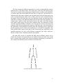
and gravity. The skeleton system was created using Maya:
Skeleton system created with Maya
The creation of the accurate human body using Maya was challenging but my
previous modeling experience helped in this process. The next step was to make sure
that the body I created would react to contact forces and gravity in the way that the
real human body does. This task required research into rigid body simulations papers
and some available source codes of the previous work (like, for example, the
6
aforementioned Novodex plug-in for Maya). The final solution to the problem of
connecting particular body parts together (for example trunk, arm and forearm chain)
was to use hinge and pin constraints. Hinge constraints were used to connect the parts
of the body that have certain limitations regarding movement, like for example the
knee joint can be moved only in two directions. The pin constraint was used for the
joint connecting the head and the neck as the head can be moved freely in various
directions (forward, backward and on the left and right sides).
Pin and hinge constraints used for particular joints in the body,
created with Maya
All of the parts of the created human body were converted into the Active Rigid
Bodies to enable interaction with applied different forces. Also the particular body
parts were parented to corresponding bones in the skeleton and the bones were orient
constrained to the corresponding body parts. This meant that with the movement of
the body part the bone that corresponds to it will be moving as well in the accurate
and realistic manner.
In order to realistically visualize accurate human body reacting to the various
forces applied, every part of the created body needed to have similar weight to the
body parts in the real life. The final figure that I created weighs the same as an
average male human (approximately 70 kg) where the head is 4.7 kg and the trunk is
15 kg.
The final figure could react accurately to the gravity force and other forces
applied to it (like air or impulse-contact forces). To make the concept as user friendly
as possible, considering that it may be required by animators without in-depth
knowledge of the rigid body simulation, the use of Maya MEL scripting language
became very helpful. The final script presents the user with the pop-up window with
several options that aid the animation of the rigid bodies, in this example, human
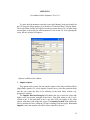
body. The final window that the user is presented with:
7
The final look of the script window,
Created with Maya MEL
The user manual on how to use the script in the most efficient way is included in
the Appendix 1.
The source code of the script Dynamics Test is included in the Appendix 2.
4. RESEARCH AND DEVELOPMENT, PROBLEMS AND SOLUTIONS
The main problem I had to solve was to create the human body with Maya
software capable of reacting to the contact forces and gravity in an accurate manner.
Below is my first design:
One of the ideas on how to create the body and connectors
8
This idea incorporates different approaches as to how to build and then connect
different parts of the human figure. The main parts of the body like forearm, head,
chest etc are separate meshes (geometries) shaped in the way where at the ends there
is a hollow space that would enable the joint bolt to be placed in. The bolt itself is a
different mesh. Each joint is shaped in the way that doesn’t allow the body parts to go
in the unwanted directions (knee joint or elbow joint have quite restricted field of
movement). Each of the body parts as well as the bolts are then converted into active
rigid bodies. In theory, this approach should work fine but brings many problems. For
example there would be many intersections between the parts of the body and the
bolts which would greatly slow down the computing time. The bounciness, friction
and other important attributes would have to be very specific in order not to allow the
geometry of the bolts to penetrate the geometry of the body parts. Also the number of
the rigid bodies would contribute to slowing down the computing process. Apart from
that, the geometry itself would not be keyframed as it was made of rigid bodies. The
bolts and the hollow spaces at the end of each of the body parts would have to be
modelled separately for each of the different connections, like elbow and knee.
Because of these issues I found this solution unacceptable.
My other idea on how to construct the body and its skeleton system was to
produce the skeleton with joints that are not connected with each other. User would
have to connect them together later after the animation (simulation) is performed. In
this example, the skeleton system would have to look like this:
One of the ideas on how to create a skeleton
9
This approach was considered due to the facts that when using the system with all
the joints connected together there were unexpected problems to solve. I tried to
apply forces not for the geometry parented to particular joints but for the joints
themselves. That caused the joint to snap in an unpredicted direction so “freeze
transformations” option had to be applied before that. When the force was applied to
the geometry parented to the particular joint (bone), everything seemed to work fine
only for that particular body part, where the other bones remained in the same
position. That’s why I came up with the idea of separating joints (see above picture).
After several tests that I carried out on how to create dynamic rigid human body I
researched more on the following, final option. This is how the body has been
constructed:
1. Create full skeleton.
2. Create geometry (body parts), move it to the desired place.
3. Delete mesh and bones history and Freeze Transformations on the mesh and
bones.
4. Geometry Constraint the mesh to the corresponding bones (it ensures that the
rotation values of the geometry are the same as the bones). After this
operation constraints can be deleted in order to adjust the position of the body
parts.
5. Orient Constraint each of the body parts to the corresponding bones.
6. Make the body parts Active Rigid Body.
7. Apply hinge/pin constraints to rigid bodies to chain them together.
8. Apply forces (such as gravity and contact forces) and create passive rigid
body objects as obstacles.
This final solution appeared to be the most efficient and the least complicated to
implement into my project. However, several problems arose whilst developing this
concept. The limits that I wanted to apply to the particular joints to prevent them from
turning in unwanted directions proved to be very unstable. After applying any limits
to the joints, these joints started to snap in unpredictable directions (even in the
directions forbidden by the characteristic features of the Hinge Constraint and also
forbidden by limits applied). To solve this problem I decided to create artificial rigid
limits. After deleting all the limits that were applied to the joints I shaped the
geometry of the body in a way so as to prevent it from moving in undesired
directions:
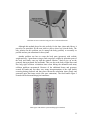
10
Final idea on how to make the body parts move in desired directions
Although this method played its role perfectly for the knee joints and elbows, it
proved to be unrealistic for the arm joints or places where legs join the body. The
only solution for this problem was to arrange the body geometry as accurately as
possible and use pin constraints for these joints.
Another problem was how to create the body parts (geometry) with realistic
weight and size. I spent hours trying to find out proper weights for particular parts of
the body and finally came up with the optimal solution: I had to give up on the
geometry that represented feet and hands. This was due to the body weight issues and
also long rigid collisions calculation times when baking the animation and many
collision problems encountered. Because of the additional bones and geometry
created for hands and feet there were many interpenetrations of the rigid bodies
occurring during playback and that slowed down the calculation times greatly and
generated quite inaccurate results (like poor animation). The final human figure I
created with skeleton and hinge/pin constraints:
Final figure with skeleton system and hinge/pin constraints
11
Having the human body figure ready I started to write the Maya MEL script that
would allow me to set up desired options quickly and easily. The final script code is
included in the Appendix 2.
The first part of the script sets up a basic pop-up window with all the options and
buttons required. What follows is a set of functions which are responsible for setting
various attributes for the contact force and some useful functions that aid production
of the final animation.
The following is an example of the function that enables the user to set up the life
span of the applied force:
global proc impulseLifespan()
{
string $selectspan[]=`ls -sl`;
body
string $selectsp;
//holds name of the rigid
for($selectsp in $selectspan)
{
int $zero=0;
int $start=`intFieldGrp -q -v1 startSpan`;
int $end=`intFieldGrp -q -v1 endSpan`;
setKeyframe -t $start ($selectsp+".impulse");
setKeyframe -t $end ($selectsp+".impulse");
setAttr ($selectsp+".impulseX") $zero;
setAttr ($selectsp+".impulseY") $zero;
setAttr ($selectsp+".impulseZ") $zero;
setKeyframe -t ($start-1) ($selectsp+".impulse");
setKeyframe -t ($end+1) ($selectsp+".impulse");
}
}
5. PROS AND CONS OF THE PROPOSED SOLUTION, FUTURE
UPGRADES
The solutions and different approaches mentioned earlier on how to capture the
human body motion are very different to each other. They are either very expensive
or very complicated. My aim has been successfully accomplished by producing a
system tackling basic problems connected with animating sequences involving
gravity and various contact forces. The script is easy to use and quick to learn. The
main feature of it is that it speeds up the animation process greatly. It produces the
animations that never look the same even if the user does not change any settings.
12
Known problems and errors:
The system I proposed is not free of some errors. For example from time to time,
depending on the strength and direction of the force applied, some parts of the body
seem to snap in unpredictable directions. In this case the user has to either adjust the
force or make some corrections to the animated skeleton. Also there is a difficulty
connected with enormous calculation times when the figure gets to the very
complicated position involving many collision calculations. From time to time, some
of the joints will twist (move) in the direction that is impossible for the human body.
This is due to the fact that there are no limits applied to the joints and the only thing
that makes them move in the desired directions is the shapes of the geometry. This
problem I mentioned earlier and have not found the solution to it as yet.
Possible upgrades:
The proposed solution would benefit greatly from some upgrades I was
considering while developing the project. One of the upgrades and probably the most
important would be to create an interactive force adjuster on the main Maya window
which would allow the user to see the direction of the force (represented for example
by an arrow). Then with the click of the button the force would be applied to the
particular part of the body and filling in the fields with the values would be no longer
necessary. I was also considering implementing some various behaviours for the
virtual character that would greatly improve the accuracy and realism of the human
body. I carried out some tests with the springs acting as the muscles attached to
different bones but they produced very strange results and forced me to abandon this
idea for the moment. Also when saving animation, it would be beneficial to have a
pop-up window that would allow the user to choose a desired directory as where to
save and how to name newly created animation.
6. SUMMARY
I believe that the script I wrote to simulate human body animation after applying
contact forces is a success and will help some animators to produce believable
animations. Although the script is simple it is capable of producing good effects. Its
simplicity allows the users to change / upgrade the script according to the
requirements. Personally it was a great challenge for me as I have never had any
scripting experience before and the Innovations Project was a great opportunity for
me to explore the scripting aspect in a deeper way. My original reason for exploring
the rigid body simulation was to use the script for a scene of a bomb explosion in my
major project animation but due to various reasons this scene will not appear in my
final major piece. I have learned basics of MEL scripting and consider it very
enjoyable. I hope to add some new features to the solution and improve its
performance and efficiency issues. My script has been tested by friends with little
knowledge of Maya who were happy with their created animations.
13
REFERENCES
[1] Stephen Ehhman, 1999, Rigid Body Simulation Tutorial,
www.cs.unc.edu/~ehmann/RigidTutorial/
[2] David Stewart, J.C. Trinkle, An Implicit Time-Stepping Scheme for Rigid
Body Dynamics with Coulomb Friction,
http://www.cs.rpi.edu/~trink/Papers/STicra.pdf
[3] A Brief History of Motion Capture for Computer Character Animation.
www.siggraph.org
[4] David Baraff, Fast Contact Force Computation for Nonpenetrating Rigid
Bodies, http://www.cs.cmu.edu/afs/cs/user/baraff/www/papers/sig94.pdf
[5] David Baraff, Physically Based Modeling,
http://www.pixar.com/companyinfo/research/pbm2001/notesg.pdf
[6] Feeling Software documentation,
www.feelingsoftware.com/Files/Nima/nima.html
[7] J. Trinkle, Trinkle’s Rigid Body Dynamics,
www.cs.rpi.edu/~trink/rigid_body_dynamics.html
Additional Reading and Research:
1. Wayne Wooten. Simulation of Leaping, Tumbling, Landing, and Balancing
Humans. PhD thesis, Georgia Institute of Technology, March 1998.
2. http://www.myphysicslab.com/collision.html
3. Rachel Weinstein, Joseph Teran, Ron Fedkiw, Dynamic Simulation of
Articulated Rigid Bodies with Contact and Collision,
http://graphics.stanford.edu/~rachellw/files/articulated.pdf
4. http://www.codercorner.com/Rigid.htm
5. Kevin Egan, Techniques for Real-Time Rigid Body Simulation,
http://www.cs.brown.edu/publications/theses/ugrad/2003/ktegan.pdf
All the internet sources of the reports, papers, tutorials and notes were checked on
the 8th of March 2006,
14
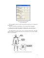
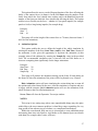
APPENDIX 1
User Manual for the Dynamics Test v.1.0
To create desired animation open the scene called human_body.ma included on
the CD. From the Maya options, go to Window Æ General Editors Æ Script Editor.
The Script Editor window will open. From the top menu choose File Æ Open Script
and navigate to the script file called dynamicsV1.mel on the CD. After opening the
script, the new window will appear:
Options available in the window:
1. Impulse Options
This option works exactly like the Impulse option in the Maya Attribute Editor
(Rigid Body options). To set the impulse (contact force), select the particular body
part the user wants the force to be affecting in the main Maya window (e.g.
perspective window).
The Impulse Direction/Strength field enables the user to enter the values (the
higher value, the greater strength of the force). First field relates to the X axis,
second to the Y axis and third to the Z axis (the XYZ rule applies to the other
options with three fields within the script). The Impulse Position field enables the
user to position the force within the 3D space (starting from the origin). Button Set
Impulse creates the impulse with all the values entered by the user.
15
Example:
Impulse Direction/Strength: 0.0
Impulse Position
: 10
0.0
10
-10
5
This setup will create the impulse (contact force) in the position X=10, Y=10
and Z=5 relatively to the origin. The direction of the impulse will be –Z with the
strength 10.
2. Quick Impulse Set
This option enables the user to apply the force in a more accurate manner and it
is recommended for most animations. Start by clicking on the button called Adjust
Position. This will create the object (pSphere1) in the origin of the scene that will
resemble the point where the force is coming out from. By using Maya Translate
Tool, move the object in the desired location (for example, if the user wants the
force to be coming out from the point just opposite the figure’s head, the object
pSphere1 should be moved to the location just opposite the head – see Fig. 1). Input
the desired values into the provided fields (XYZ rule), where the higher value will
represent greater strength of the force. Select the body part you want the force to be
affecting in the main window and click on the Create Impulse to finalise the action
of creating the force.
Fig.1.
Example:
Impulse Direction:
0.0
0.0
10
This setup will create the impulse coming out of the pSphere1 location with the
strength 10 and direction Z.
3. Impulse Lifespan
16
This option allows the user to set the lifespan (duration of the force affecting the
body) of the contact forces (in frames). In the field Start enter the number of the
frame from which the force should start working and in the End field input the
number of the frame on which the force should stop affecting the body. This option
enables user to flexibly set the force – whether it is just quick impulse (for example
punch or kick) or long lasting impulse (for example drag).
Example:
Start: 3
End : 10
This setup will set the length of the contact force to 7 frames (between frames 3
and 10 of the animation).
4. Animation Options
This option enables the user to define the length of the whole simulation by
entering the numbers of the first ( Start Time ) and the last ( End Time ) frames of
the animation. It also gives the opportunity to keyframe the animation (in this
example joints of the skeleton) by entering the Sample By value in the provided
field. The recommended simulation time is between 100 and 200 frames as it
increases computing time significantly for the longer animations.
Example:
Start Time:
End Time :
Sample By:
20
50
4
This Setup will produce the animation starting on the frame 20 and ending on
the frame 50 where the animation of the joints will be keyframed every 4 frames.
Bake Animation option will start simulating the action taking into account all
the options and values entered by the user. After the simulation is complete and user
is happy with the outcome, Save Animation option will save the animation of the
whole skeleton to the file called animation.ma.
Button Close will close the Dynamics Test script window.
NOTES:
This script is in a testing stage where some unpredictable things may take place
within Maya (the most common problem is when Maya stops responding for very
long period of time when trying to calculate very complicated simulations).
Within the scene human_body.ma user is encouraged to create additional props
and turning them into active/passive rigid bodies so the human figure can interact
with them (for example chairs, stairs, walls etc.).
17
The output file name animation.ma should be renamed to something else in
order to avoid overwriting by newly created animations.
The project comes with the support of the CD where the user can find all the
files necessary to create animations (human_body.ma and dynamicsV1.mel) and
also the movie file presenting the features of the system showing some of the
finished animations using the script.
18
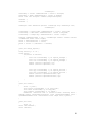
APPENDIX 2
Source code for the Dynamics Test MEL script
/*------Dynamics Test V1.0 by Marcin Kolendo 2006
--------*/
global proc make_body()
{
string $window ="make_body";
if(`window -exists $window`)
deleteUI $window;
dynamics_window($window);
window -e -wh 415 430 $window;
}
global proc dynamics_window(string $window)
{
window -title "Dynamics Test V1.0"
-maximizeButton false
-menuBar true $window;
showWindow $window;
menu -label "Menu" -tearOff true;
menuItem -label "Instructions" -c("confirmDialog -title \"Instructions\" message \"1.Set the strenght and direction of the impulse.\\n2.Click 'Create
Animation' button.\\n3.Click 'Save Animation' button.\\n4.Refer to the Readme
file for more options.\" -button \"OK\";");
menuItem
-label
"About"
-c("confirmDialog
-title
\"About\"
-message
\"Dynamics Test V1.0\\nemail: [email protected]\" -button \"OK\";");
columnLayout -adjustableColumn true;
frameLayout -label "Impulse Options" -labelAlign "top" -borderStyle "in";
columnLayout;
floatFieldGrp -l "Impulse Direction/Strenght" -numberOfFields 3 -value1 0 value2 0 -value3 0 impulse_Strenght;
floatFieldGrp -l "Impulse Position" -numberOfFields 3 -value1 0 -value2 0 value3 0 impulse_Position;
button -label "Set Impulse" -command ("change_impulse");
setParent ..;
setParent ..;
frameLayout -label "Quick Impulse Set" -labelAlign "top" -borderStyle "in";
columnLayout;
floatFieldGrp -l "Impulse Direction" -numberOfFields 3 -value1 0 -value2 0 value3 0 impulse_Strenghtx;
rowLayout -numberOfColumns 2 -adj 2 -columnAlign2 "center" "center" columnAttach2 "both" "both";
button -label "Adjust Position" -command ("impulse_position_set");
button -label "Create Impulse" -command ("impulse_position");
setParent ..;
setParent ..;
setParent ..;
frameLayout -label "Impulse Lifespan" -labelAlign "top" -borderStyle "in";
19
columnLayout;
intFieldGrp -l "Start" -numberOfFields 1 -value1 1 startSpan;
intFieldGrp -l "End" -numberOfFields 1 -value1 10 endSpan;
button -label "Set Lifespan" -command ("impulseLifespan");
setParent ..;
setParent ..;
frameLayout -label "Animation Options" -labelAlign "top" -borderStyle "in";
columnLayout;
floatFieldGrp -l "Start Time" -numberOfFields 1 -value1 1 start_Time;
floatFieldGrp -l "End Time" -numberOfFields 1 -value1 10 end_Time;
floatFieldGrp -l "Sample By" -numberOfFields 1 -value1 1 sample;
rowLayout -numberOfColumns 3 -adj 3 -columnAlign3 "center" "center" "center"
-columnAttach3 "both" "left" "right";
button -l "Bake Animation" -c "create";
button -l "Save Animation" -c "save";
button -l "Close" -c ("deleteUI " + $window);
}
global proc change_impulse()
{
string $selects[]=`ls -sl`;
string $select;
for($select in $selects)
{
float $ix=`floatFieldGrp -q -v1 impulse_Strenght`;
float $iy=`floatFieldGrp -q -v2 impulse_Strenght`;
float $iz=`floatFieldGrp -q -v3 impulse_Strenght`;
setAttr ($select+".impulseX") $ix;
setAttr ($select+".impulseY") $iy;
setAttr ($select+".impulseZ") $iz;
float $px=`floatFieldGrp -q -v1 impulse_Position`;
float $py=`floatFieldGrp -q -v2 impulse_Position`;
float $pz=`floatFieldGrp -q -v3 impulse_Position`;
setAttr ($select+".impulsePositionX") $px;
setAttr ($select+".impulsePositionY") $py;
setAttr ($select+".impulsePositionZ") $pz;
}
}
global proc create()
{
select -r joint7 ;
float $start=`floatFieldGrp -q -v1 start_Time`;
float $end=`floatFieldGrp -q -v1 end_Time`;
float $sample=`floatFieldGrp -q -v1 sample`;
bakeResults -simulation true -t ($start+":"+$end) -hierarchy below sampleBy $sample -disableImplicitControl false -preserveOutsideKeys false sparseAnimCurveBake false -controlPoints false -shape false {"joint7"};
}
global proc save()
{
select -cl ;
select -add lowerneck ;
select -add head ;
20
select -add
select -add
select -add
select -add
select -add
select -add
select -add
select -add
select -add
select -add
select -add
select -add
delete;
left_tigh ;
right_tigh ;
right_calf ;
left_calf ;
right_arm ;
left_arm ;
right_forearm ;
left_forearm ;
bowel ;
stomach ;
chest ;
gravityField1 ;
select -r joint7;
select -add joint1 joint2 joint3 joint4 joint5 joint6 joint8 joint9
joint10 joint11 joint12 joint13 joint14
joint15 joint16 joint17 joint18;
file -rename "animation.ma";
file -typ "mayaAscii" -es -chn 1;
}
global proc impulse_position_set()
{
polySphere -r 0.2 -sx 3 -sy 3 -ax 0 1 0 -tx 1 -ch 1; //creates sphere
}
global
{
string
string
select
string
string
proc impulse_position()
$selectrigid[]=`ls -sl`; //holds name of the rigid body
$selectrig;
-r pSphere1;
$selectsphere[]=`ls -sl`;//holds name of the sphere
$selectsph;
for($selectrig in $selectrigid)
{
//get
float
float
float
select's xyz
$selectX=`getAttr $selectsphere.tx`;
$selectY=`getAttr $selectsphere.ty`;
$selectZ=`getAttr $selectsphere.tz`;
setAttr ($selectrig+".impulsePositionX") $selectX;
setAttr ($selectrig+".impulsePositionY") $selectY;
setAttr ($selectrig+".impulsePositionZ") $selectZ;
}
select -r $selectrig;
string $selectsx[]=`ls -sl`;
string $selectx;
for($selectx in $selectsx)
{
float $ix=`floatFieldGrp -q -v1 impulse_Strenghtx`;
float $iy=`floatFieldGrp -q -v2 impulse_Strenghtx`;
float $iz=`floatFieldGrp -q -v3 impulse_Strenghtx`;
setAttr ($selectx+".impulseX") $ix;
setAttr ($selectx+".impulseY") $iy;
setAttr ($selectx+".impulseZ") $iz;
}
}
21
global proc impulseLifespan()
{
string $selectspan[]=`ls -sl`;
string $selectsp;
//holds name of the rigid body
for($selectsp in $selectspan)
{
int $zero=0;
int $start=`intFieldGrp -q -v1 startSpan`;
int $end=`intFieldGrp -q -v1 endSpan`;
setKeyframe -t $start ($selectsp+".impulse");
setKeyframe -t $end ($selectsp+".impulse");
setAttr ($selectsp+".impulseX") $zero;
setAttr ($selectsp+".impulseY") $zero;
setAttr ($selectsp+".impulseZ") $zero;
setKeyframe -t ($start-1) ($selectsp+".impulse");
setKeyframe -t ($end+1) ($selectsp+".impulse");
}
}
make_body()
22