1
Project no.
035086
Project acronym
EURACE
Project title
An Agent-Based software platform for European economic policy design with heterogeneous
interacting agents: new insights from a bottom up approach to economic modelling and simulation
Instrument STREP
Thematic Priority IST FET PROACTIVE INITIATIVE “SIMULATING EMERGENT PROPERTIES IN
COMPLEX SYSTEMS”
Deliverable reference number and title
D8.1: Release of the agent-based software platform
for economic policy design
Due date of deliverable:
28/02/2009
Actual submission date:
28/02/2009
Start date of project: September 1st 2006
Duration: 39 months
Organisation name of lead contractor for this deliverable
University of Sheffield - USFD
Revision 1
Project co-funded by the European Commission within the Sixth Framework Programme (2002-2006)
Dissemination Level
Public
PU
Restricted to other programme participants (including the Commission Services)
PP
Restricted to a group specified by the consortium (including the Commission Services)
RE
Confidential, only for members of the consortium (including the Commission Services)
CO
X
Contents
1 Introduction
1
2 Working with FLAME
2.1 Swarm Example . . . . . . . . . . . . . . . . . . . . . . . . . . . . . . . . . . . .
2.2 Transition Functions . . . . . . . . . . . . . . . . . . . . . . . . . . . . . . . . . .
2.3 Memory and States . . . . . . . . . . . . . . . . . . . . . . . . . . . . . . . . . . .
2
3
4
4
3 Model Description
3.1 Tags within the XModel . . .
3.2 Model in Multiple Files . . .
3.3 Environment . . . . . . . . .
3.3.1 Constant Variables . .
3.3.2 Function Files . . . .
3.3.3 Time Units . . . . . .
3.3.4 Data Types . . . . . .
3.4 Agents . . . . . . . . . . . . .
3.4.1 Agent Memory . . . .
3.4.2 Agent Functions . . .
3.4.3 Function Condition . .
3.4.4 Time conditions . . .
3.4.5 Messages in and out of
3.4.6 Message Filters . . . .
3.5 Messages . . . . . . . . . . .
.
.
.
.
.
.
.
.
.
.
.
.
.
.
.
6
6
7
7
8
8
8
9
10
10
11
11
13
13
13
14
.
.
.
.
15
15
16
16
16
5 Model Execution
5.1 Xparser Generated Files . . . . . . . . . . . . . . . . . . . . . . . . . . . . . . . .
5.2 Start States Files 0.xml . . . . . . . . . . . . . . . . . . . . . . . . . . . . . . . .
17
17
18
6 Installation Notes on FLAME
6.1 MinGW . . . . . . . . . . . .
6.2 Extra Useful Installations . .
6.2.1 GDB . . . . . . . . . .
6.2.2 Dotty . . . . . . . . .
6.3 Libmboard . . . . . . . . . .
18
18
19
19
19
19
. . . . . .
. . . . . .
. . . . . .
. . . . . .
. . . . . .
. . . . . .
. . . . . .
. . . . . .
. . . . . .
. . . . . .
. . . . . .
. . . . . .
Functions
. . . . . .
. . . . . .
4 Model Implementation
4.1 Accessing Agent Memory Variables
4.1.1 Using Model Data Types .
4.1.2 Using Dynamic Arrays . . .
4.2 Sending and receiving messages . .
.
.
.
.
.
.
.
.
.
.
.
.
.
.
.
.
.
.
.
.
.
.
.
.
.
.
.
.
.
.
.
.
.
.
.
.
.
.
.
.
.
.
.
.
.
.
.
.
.
.
.
.
.
.
.
.
.
.
.
.
.
.
.
.
.
.
.
.
.
.
.
.
.
.
.
.
.
.
.
.
.
.
.
.
.
.
.
.
.
.
.
.
.
.
.
.
.
.
.
.
.
.
.
.
.
.
.
.
.
.
.
.
.
.
.
.
.
.
.
.
.
.
.
.
.
.
.
.
.
.
.
.
.
.
.
.
.
.
.
.
.
.
.
.
.
.
.
.
.
.
.
.
.
.
.
.
.
.
.
.
.
.
.
.
.
.
.
.
.
.
.
.
.
.
.
.
.
.
.
.
.
.
.
.
.
.
.
.
.
.
.
.
.
.
.
.
.
.
.
.
.
.
.
.
.
.
.
.
.
.
.
.
.
.
.
.
.
.
.
.
.
.
.
.
.
.
.
.
.
.
.
.
.
.
.
.
.
.
.
.
.
.
.
.
.
.
.
.
.
.
.
.
.
.
.
.
.
.
.
.
.
.
.
.
.
.
.
.
.
.
.
.
.
.
.
.
.
.
.
.
.
.
.
.
.
.
.
.
.
.
.
.
.
.
.
.
.
.
.
.
.
.
.
.
.
.
.
.
.
.
.
.
.
.
.
.
.
.
.
.
.
.
.
.
.
.
.
.
.
.
.
.
.
.
.
.
.
.
.
.
.
.
.
.
.
.
.
.
.
.
.
.
.
.
.
.
.
.
.
.
.
.
.
.
.
.
.
.
.
.
.
.
.
.
.
.
.
.
.
.
.
.
.
.
.
.
.
.
.
.
.
.
.
.
.
.
.
.
.
.
.
.
.
.
.
.
.
.
.
.
.
.
.
.
.
.
.
.
.
.
.
.
.
.
.
.
.
.
.
.
.
.
.
.
.
.
.
.
.
.
.
.
.
.
.
.
.
.
.
.
.
.
.
.
.
.
.
.
.
.
.
.
.
.
.
.
.
.
.
.
.
.
.
.
.
.
.
.
.
.
.
.
.
.
.
.
.
.
.
.
.
.
.
.
.
.
.
.
.
.
.
.
.
.
.
.
.
.
.
.
.
.
.
.
.
.
.
.
.
.
.
.
.
.
.
.
.
.
.
.
.
.
.
.
.
.
.
.
.
.
.
.
.
.
.
.
.
.
.
.
.
.
.
.
.
.
.
.
.
.
.
.
.
.
.
.
.
.
.
.
.
.
.
.
.
7 Running a Simulation
20
8 Notes for the Programmers of FLAME
8.1 Memory Allocation and its Problems . .
8.1.1 Dynamic Arrays . . . . . . . . .
8.1.2 Data Types . . . . . . . . . . . .
8.1.3 Agent Memory Management . .
8.2 Agent Execution . . . . . . . . . . . . .
i
.
.
.
.
.
.
.
.
.
.
.
.
.
.
.
.
.
.
.
.
.
.
.
.
.
.
.
.
.
.
.
.
.
.
.
.
.
.
.
.
.
.
.
.
.
.
.
.
.
.
.
.
.
.
.
.
.
.
.
.
.
.
.
.
.
.
.
.
.
.
.
.
.
.
.
.
.
.
.
.
.
.
.
.
.
.
.
.
.
.
.
.
.
.
.
.
.
.
.
.
.
.
.
.
.
.
.
.
.
.
.
.
.
.
.
20
20
21
21
21
21
8.3
8.4
Communication . . . . . . . . . . . . . . . . . . . . . . . . . . . . . . . . . . . . .
Libmboard . . . . . . . . . . . . . . . . . . . . . . . . . . . . . . . . . . . . . . .
22
23
9 XParser Distribution
23
10 XParser generated files
23
11 XParser Versions
26
12 Example Models
27
A XML DTD
27
ii
Abstract
This report presents the deliverable D8.1 accounting for the software descriptions of the
FLAME framework as employed in EURACE for writing the various market models. This
deliverable acts as part of the work package 8 which involves the official release of FLAME
Version 1.0 which is an agent-based modelling framework for performing economic modelling.
iii
1
Introduction
FLAME (Flexible Large-scale Agent-based Modelling Environment) is a tool which allows modelers from all disciplines, economics, biology or social sciences to easily write their own agent-based
models. The environment is a first of its kind which allows simulations of large concentrations
of agents to be run on parallel computers without any hindrance to the modelers themselves.
The FLAME framework is a tool which enables creation of agent-based models that can be
run on high performance computers (HPCs). The framework is based on the logical communicating extended finite state machine theory (X-machine) which gives the agents more power to
enable writing of complex models for large complex systems.
The agents are modelled as communicating X-machines allowing them to communicate
through messages being sent to each other as per designed by the modeller. This information is automatically read by the FLAME framework and generates a simulation program which
enables these models to be parallelised efficiently over parallel computers.
The simulation program for FLAME is called the Xparser. The Xparser is a series of
compilation files which can be compiled with the modeller’s files to produce a simulation package
for running the simulations. Various tools have to be installed with the Xparser to allow the
simulation program to be produced. These have been explained in the Section 6.
Various parallel platforms like, SCARF, HAPU or IceBerg, have been used in the development process to test the efficiency of the FLAME framework. This work was done in conjunction
with the STFC unit (Science and Technology Facilities Council) and more details of the results
obtained can be found in ‘Deliverable 1.4: Porting of agent models to parallel computers’.
Figure 1: Block diagram of the Xparser, the FLAME simulation program. Blocks in blue are
the files automatically generated. The green blocks are modeller files.
• Model.xml - should contain the whole structure of your model i.e Agent descriptions,
memory variables, functions, messages
• Functions.c - should contain the implementations of the functions specified in Model.xml
• 0.xml - should contain the initial states of the memory variables of the agents i.e Initialisation of all parameters
1
The number of the resulting XML files depends on the number of iterations you specify to
run your model (through Main.exe).
FLAME was employed in EURACE to write economic models of the European markets.
Various documents were released as part of Deliverable 8.1 which include:
• User Manual for FLAME - A detailed manual of how a user can write his or her own
economic model using FLAME.
• Getting started with FLAME - A brief summary of the software tools required to be installed to work with FLAME. This contains details on installing for the different platforms
like Windows, Linux or Mac systems.
• Implementation notes for FLAME - A detailed description of the implementation details
of FLAME for other FLAME developers to use while working with FLAME.
• Example tutorials - A set of tutorial slides to teach modelers how to write their own models
in FLAME and run example models.
These documents have been summarised in this report as separate sections.
2
Working with FLAME
This section presents a comprehensive guide to the keywords and functions available in the
FLAME environment for the modellers to write their own agent models to facilitate their research. This user manual describes how to create a model description and write implementation
code for the agents.
Traditionally specifying software behaviour has used finite state machines to express its
working. Extended finite state machines (X-machines) are more powerful than the simple finite
state machine as it gives the model more flexibility than a traditional finite state machine.
FLAME uses X-machines to represent all agents acting in the system. Each would thus
possess the following characteristics:
• A finite set of internal states of the agent.
• Set of transitions functions that operate between the states.
• An internal memory set of the agent.
• A language for sending and receiving messages among agents.
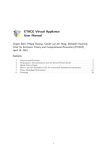
Figure 2 shows the structure of how two X-machines will communicate. The machines communicate through a common message board, to which they post and read from their messages.
Using conventional state machines to describe the state-dependent behaviour of a system by outlining the inputs to the system, but this failed to include the effect of messages being read and
the changes in the memory values of the machine. X-Machines are an extension to conventional
state machines that include the manipulation of memory as part of the system behaviour, and
thus are a suitable way to specify agents. Describing a system in FLAME includes the following
stages:
• Identifying the agents and their functions.
• Identify the states which impose some order of function execution with in the agent.
2
• Identify the input messages and output messages of each function (including possible filters
on inputs which will be explained in Section 3.4.6).
• Identify the memory as the set of variables that are accessed by functions (including
possible conditions on variables for the functions to occur).
Memory
Messages out
Internal
states
Messages in
Agent X-machine 1
Agent X-machine 2
Message Board
Transition
functions are influenced
by messages and memory
Figure 2: How two agent x-machines communicate. The agents send and read messages from
the message board which maintains a database of all the messages sent by the agents.
2.1
Swarm Example
A swarm model in a model which presents the behaviour of birds flocking together. The individual birds follow simple rules, but collectively they produce complex behaviour of the group,
as observed in nature. This simple flocking model involves birds to sense where other birds are
and then respond accordingly. The activities or functions they perform are:
• Observe if there is a bird nearby.
• Adjust bird position, direction and velocity accordingly.
Converting this model into an agent-based model requires visualising the model as a collection
of agents. As the only individuals involved in the model are birds, agents will be representing
birds. The functions these bird agents would perform will be:
• Signal. The agent would send information of its current position.
• Observe. The agent would read in the positions from other agents and possibly change
velocity.
• Respond. The agent would update position via the current velocity.
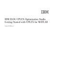
The functions would occur in an order as shown in Figure 3. The complete figure represents
the functions the agents would be performing during one iteration1 .
Figure 4 depicts a situation where their would be conditions added to the functions of the
agents. For instance, in the swarm model, there could be a condition added to the z-axis value
3
start
signal
1
observe
2
respond
end
Figure 3: Swarm model including states
z>0
start
signal
1
observe
2
flying
end
z == 0
resting
Figure 4: Swarm model including function conditions
to determine which response function to perform for the agent. If z is more than zero, the agent
would be flying, else if z is zero, then the agent is stationary.
The message being used for communication between the agents, in the model, is a signal
message, which is the output from ‘signal’ function and the input to the ‘observe’ function
(Figure 5). This message includes the position of the agent that sent it with the x, y and z
coordinates (Table 1).
z>0
start
signal
1
observe
2
flying
end
z == 0
resting
signal
Figure 5: Swarm model including messages
An important factor to note here is that FLAME carries the features of a filter which can
be added to the messages. This filter can ensure that only the messages in the agents viewing
distance are being read, preventing each agent to traverse through all the messages on the
message board. The filter will be a formula involving the position contained in the message (the
position of the sending agent) and the receiving agent position.
2.2
Transition Functions
Transition functions allow agents to change the state in which they are in, modifying their
behaviour. Transition functions take as input the current state s1 of the agent, current memory
value m1 and the possible arrival of a message that the agent reads t1 . Depending on these three
values the agent changes to another state s2 , updates the memory to m2 and optionally sends
a message t2 .
There could be situations where some of the transition functions do not depend on the
incoming messages. Agent transition functions may also be expressed in terms of stochastic
rules, which allows the multi-agent systems to be called stochastic systems.
2.3
Memory and States
The difference between the internal set of states and the internal memory set allows the added
flexibility when modelling systems. There can be agents with one internal state and all the com1
FLAME prevents the agents to loop back due to parallelization constraints.
4
Type
double
double
double
Name
px
py
pz
Description
x-axis position
y-axis position
z-axis position
Table 1: Signal Message
plexity defined in the memory or equivalently, there could be agents with a trivial memory, with
the complexity then bound up in a large state space. It depends on the modeller’s perspective
on how he/she write the model and where the complexity is added.
In FLAME, one iteration is taken as a standalone run of a simulation. Once all the functions
in that iteration have taken place, the message board is emptied, deleting all the messages. This
means that messages cannot be sent between iterations, thus models have to be written in a
way which considers this.
Table 2 describes the memory variables being used by the bird agents in the swarm model.
Type
double
double
double
double
double
double
Name
px
py
pz
vx
vy
vz
Description
position in x-axis
position in y-axis
position in z-axis
velocity in x-axis
velocity in y-axis
velocity in z-axis
Table 2: Swarm Agent Memory
Modellers can add more variables to the agent memory as they see required. Table 3 represents a transition table presentation of the swarm model. The terms in the table have been
defined below:
• Current State - is the state the agent is currently in.
• Input - is any inputs into the transition function.
• Mpre - are any preconditions of the memory on the transition.
• Function - is the function name.
• Mpost - is any change in the agent memory.
• Output - is any outputs from the transition.
• Next State - is the next state that is entered by the agent.
Current State
start
1
2
2
Input
Mpre
signal
x>0
x == 0
Function
signal
observe
flying
resting
Mpost
(velocity updated)
(position updated)
(position updated)
Table 3: Swarm Agent Transition Table
5
Output
signal
Next State
1
2
end
end
The next Section 3 describes how a model can be written up in the XML format that FLAME
can understand. Section 4 discusses how to implement the individual agent functions, i.e. Mpost
from the transition table. Section 5 on model execution describes how to use the tools in FLAME
to generate a simulation program and execute the simulations.
3
Model Description
Models descriptions are formatted in XML (Extensible Markup Language) tag structures to
allow easy human and computer readability. This also allows easier collaborations between the
developers writing the application functions that interact with model definitions in the XML.
The DTD (Document Type Definition) of the XML document is currently located at:
http://eurace.cs.bilgi.edu.tr/XMML.dtd
For users who are familiar with the HTML structure, a XML document is structured in a
similar way as a nested tree structure, where tags contain data or other tags within them. This
structure can be condensed into one level or a number of levels within the parent levels. In
FLAME, the start and the end of a model file looks like as follows:
<?xml version="1.0" encoding="ISO-8859-1"?> <!DOCTYPE xmodel SYSTEM
"http://eurace.cs.bilgi.edu.tr/XMML.dtd"> <xmodel version="2">
<name>Model_name</name> <version>the version</version>
<description>a description</description> ... </xmodel>
The complete model is contained within the tag level of ‘xmodel’ . The name of the model is
the name of the model being modelled, version denotes the version number of the model. The
description tags allows the model description to be contained in it for modellers to make notes.
3.1
Tags within the XModel
Defining the xmodel is the parent level in the XML file being read by FLAME. This xmodel
can be condensed into a number of different tag trees which contain further details about the
model. These tags can contain information about:
• Other models - Other models can be enabled or disabled when being plugged into a
model. This is to allow modeller to test more than one model at a time as well as mix a
number of models together.
• Environment - The environment contains the global variables of the model in which the
agents exist in. Sometimes modellers make the environment act as an agent too with
functions and memory states. But this requires another agent to be listed. Here the
environment can act as global with constant values for all agents. The environment can
contain the following information,
– Constant variables - Global variables.
– Location of function files - Location where the functions or C files of the agents are
located.
– Time units - Enables the programming of calenders, which can be assigned to each
function to enable it to be active only at specific times during the simulation.
– Data types - Agent memories can use data structures for some of the variables instead
of the traditional C variable types like int, char or double. These data types can be
defined by the modeller to contain more than one type or array within it.
6
• Agent types - The agents involved in the system. For instance, in the swarm model,
there was only one type of agent the bird agents. In an alternate model of the predator
prey model there are two agent types, the fix and the rabbit. These depend on the model
being modelled and the modeller’s perspectives. The agents are defined by the ‘xagent’
tag and can contain the following information,
–
–
–
–
Name - Name of the agent type
Description - Textual description of the agent.
Memory - A list of the memory variables for each type of agent.
Functions - A list of functions the agent can perform. These functions are encapsulated with states like the current and the next state to move to after this function has
been executed. The functions would also contain the names of the messages being
read in or output from the functions.
• Message types - These are a list of all the messages being used in the model. The details
with in the message are,
– Name - Name of the message.
– Description - Textual description of the message.
– Variables - Variables encapsulated with in the message.
Refer to the Appendix to see how these tags are brought together in one model XML file.
3.2
Model in Multiple Files
It is possible to define a model in a collection of multiple files. FLAME reads a model from
multiple files as if the model was defined in one file. This capability allows different parts of
a model to be enabled or disabled easily. For example if a model includes different versions of
a sub-model, these can be exchanged, or a subsystem of a model can be disabled to see how
it affects the model. Alternatively this capability could be used as a hierarchy, for example a
‘body’ model could include a model of the ‘cardiovascular system’ that includes a model of the
‘heart’. The following tags show the inclusion of two models, one is enabled and one disabled:
<models>
<model><file>sub_model_1.xml</file><enabled>true</enabled></model>
<model><file>sub_model_2.xml</file><enabled>false</enabled></model>
</models>
3.3
Environment
The environment of a model holds information that maybe required by a model but is not part
of an agent or a message. This includes:
• Constant variables - for setting up different simulations easily.
• Location of function files - the path to the implementations of agent functions in C files.
• Time units - for easily activating agent functions dependent on time periods.
• Data types - user defined data types used by agent memory or message variables other
that typical C data types.
This notion of environment does not correspond to an environment that would be a part of a
model where agents would interact with the environment. Anything that can change in a model
must be represented by an agent, therefore if a model includes a changeable environment that
agents can interact with, this in itself must be represented by an agent.
7
3.3.1
Constant Variables
Constant variables can be set up as part of a simulation for the runs. These are defined as
follows:
<constants>
<variable>
<type>int</type><name>my_constant</name>
<description>value read in initial simulation settings</description>
</variable>
</constants>
Constant Variables refers to the global values used in the model. These can also be defined
in a separate header H file which can then be included in one of the functions C file. The header
file should contain the global variable as:
#define <varname> <value>
This file has to be saved as ‘my header.h’ file, include this file into one of the function files
so that the compiler knows about these arguments.
3.3.2
Function Files
Function files hold the source code for the implementation of the agent functions. These are
programmed in C language. They are included in the compilation script (Makefile) of the
produced model:
<functionFiles>
<file>function_source_code_1.c</file>
<file>function_source_code_2.c</file>
</functionFiles>
3.3.3
Time Units
Time units are used to define time periods that agent functions act within. For example a model
that uses a calendar based time system could take a day to be the smallest time step, i.e. one
iteration. Other time units can then use this definition to define other time units, for example
weeks, months, and years.
A time unit contains:
• Name - name of the time unit.
• Unit - can contain ‘iteration’ or other defined time units.
• Period - the length of the time unit using the above units.
An example of a calendar based time unit set up is given below:
<timeUnits>
<timeUnit>
<name>daily</name>
<unit>iteration</unit>
<period>1</period>
</timeUnit>
8
<timeUnit>
<name>weekly</name>
<unit>daily</unit>
<period>5</period>
</timeUnit>
<timeUnit>
<name>monthly</name>
<unit>weekly</unit>
<period>4</period>
</timeUnit>
<timeUnit>
<name>quarterly</name>
<unit>monthly</unit>
<period>3</period>
</timeUnit>
<timeUnit>
<name>yearly</name>
<unit>monthly</unit>
<period>12</period>
</timeUnit>
</timeUnits>
These time units can be added to the functions, when they are listed as part of the agent.
These time units act as conditions on the functions. This has been discussed in Section 3.4.3.
3.3.4
Data Types
Data types are user defined data types that can be used in a model. They are a structure for
holding variables. Variables can be a:
• Single C fundamental data types - int, float, double, char.
• Static array - of any size for example ten is written as ‘variable name[10]’.
• Dynamic array - available by placing ‘ array’ after the data type name: variable name array.
• User defined data type - defined before the current data type.
The example below contains a variable of data structure position which contains the x, y
and z position in one structure. The position data structure can then be a data type in the line
data structure.
<dataTypes>
<dataType>
<name>position/name>
<description>position in 3D using doubles</description>
<variables>
<variable><type>double</type><name>x</name>
<description>position on x-axis</description>
</variable>
<variable><type>double</type><name>y</name>
9
<description>position on y-axis</description>
</variable>
<variable><type>double</type><name>z</name>
<description>position on z-axis</description>
</variable>
</variables>
</dataType>
<dataType>
<name>line</name>
<description>a line defined by two points</description>
<variables>
<variable><type>position</type><name>start</name>
<description>start position of the line</description>
</variable>
<variable><type>position</type><name>end</name>
<description>end position of the line</description>
</variable>
</variables>
</dataType>
</dataTypes>
3.4
Agents
A model has to constitute agents. These agents are defined as their type in the model XML file.
An agent type contains a name, a description, memory, and functions:
<agents>
<xagent>
<name>Agent_Name</name>
<description></description>
<memory>
...
</memory>
<functions>
...
</functions>
</xagent>
3.4.1
Agent Memory
Agent memory defines variables, where variables are defined by their type, C data types or user
defined data types from the environment, a name, and a description:
<memory>
<variable><type>int</type><name>id</name>
<description>identity number</description>
</variable>
<variable><type>double</type><name>x</name>
<description>position in x-axis</description>
</variable>
<variable><type>position</type><name>xyz</name>
<description>position in x-axis, y-axis, z-axis</description>
</variable>
</memory>
10
Agent memory variables can be defined as being constant by using the ¡constant¿ tag and
defining it to be true. This will stop the variable being allowed to be changed. This helps
message communication in parallel when input filters are dependent upon constant agent memory
variables.
<variable>
<type>int</type><name>id</name><constant>true</constant><description></description>
</variable>
3.4.2
Agent Functions
The model XML file requires the agent functions to be listed as well to tell FLAME when the
functions will be called in from the C files. An agent function contains:
• Name - the function name which must correspond to an implemented function name
• Description
• Current state - the current state the agent has to be in for this function to execute.
• Next state - the next state the agent will transition to after the function.
• Condition - a possible condition of the function transition.
• Inputs - the possible input messages.
• Outputs - the possible output messages.
And as tags, the XML file will contain:
<function>
<name>function_name</name>
<description>function description</description>
<currentState>current_state</currentState>
<nextState>next_state</nextState>
<condition>
...
</condition>
<inputs>
...
</inputs>
<outputs>
...
</outputs>
</function>
The current state and next state tags hold the names of states. This is the only place
where states are defined. State names must coordinate with other functions states to produce a
transitional graph from the start state to end states.
3.4.3
Function Condition
A function can have a condition on its transition. This condition can include conditions on the
agent memory and also on any time units defined in the environment. Each transition will take
the agent from a starting state to an end state at the end of the simulation.
11
Each possible transition must be mutually exclusive. This means that if a certain condition
is true on one part of the branch of functions, there should be an alternate branch which would
be the opposite of this condition. This will ensure the model does not halt in the middle during
simulation if the condition fails. A function named ‘idle’ is available to be used for functions
that do not require an implementation and a reverse of the conditions.
Conditions (that are not just time unit based) take the form:
• lhs - left hand side of comparison.
• op - the comparison operator.
• rhs - the right hand side of the comparison.
Or in tags form:
<lhs></lhs><op></op><rhs></rhs>
Sides to compare (lhs or rhs) can be either a value, denoted within value tags or a formula.
Values and formulas can include agent variables, which are preceded by ‘a’, or message variables,
which are preceded by ‘m.’.
a.agent_var
m.message_var
The comparison operator, op, can be one of the following comparison functions:
• EQ - equal to.
• NEQ - not equal to.
• LEQ - less than or equal to.
• GEQ - greater than or equal to.
• LT - less then.
• GT - greater than.
• IN - an integer (in lhs) is a member of an array of integers (in rhs).
Or one of the following logic operators can be used as well:
• AND
• OR
The operator ‘NOT’ can be used by placing ‘not’ tags around a comparison rule. For example
the following tagged rule describes the condition being true when the ‘z’ variable of the agent is
greater than zero and less than ten:
12
<condition>
<lhs>
<lhs><value>a.z</value></lhs>
<op>GT</op>
<rhs><value>0.0</value></rhs>
</lhs>
<op>AND</op>
<rhs>
<not>
<lhs><value>a.z</value></lhs>
<op>LT</op>
<rhs><value>10.0</value></rhs>
</not>
</rhs>
</condition>
3.4.4
Time conditions
A condition can also depend on any time units described in the environment. For example the
following condition is true when the agent variable ‘day of month to act’ is equal to the number
of iterations since of the start, the phase, of the ‘monthly’ period, i.e. twenty iterations as
defined in the time unit:
<condition>
<time>
<period>monthly</period>
<phase>a.day_of_month_to_act</phase>
</time>
</condition>
The condition allows the function to run monthly at the phase of day of month to act.
The day of month to act is a variable extracted from the agent memory and is thus defined
as a.day of month to act.
3.4.5
Messages in and out of Functions
Functions can have input and output message types. For example, the following example the
function takes message types ‘a’ and ‘b’ as inputs and outputs message type ‘c’:
<inputs>
<input><messageName>a</messageName></input>
<input><messageName>b</messageName></input>
</inputs> <outputs>
<output><messageName>c</messageName></output>
</outputs>
3.4.6
Message Filters
Message filters can be applied to message inputs to allow the messages to be filtered. Filters
are defined similar to function conditions but include message variables which are prefixed by
an ‘m’.
The various tags associated with message filters are as follows:
• Conditions on the value of a variable within the message. This is denoted by the lhs, op
and rhs operators.
13
The following example filter only allows messages where the agent variable ‘id’ is equal to
the message variable ‘worker id’,
<input>
<messageName>firing</messageName>
<filter>
<lhs><value>a.id</value></lhs>
<op>EQ</op>
<rhs><value>m.worker_id</value></rhs>
</filter>
<random>true<random>
</input>
The previous example also includes the use of a random tag, set to false, to show that the
input does not need to be randomised, as randomising input messages can be computationally expensive. By default all message inputs are not being randomised.
• IN tag. Message input filters can now accept the ‘IN’ operator. The IN operator accepts
a single integer in the <lhs> tag and an integer array (static or dynamic) in the <rhs>
tag. The filter returns true for any single integer that is a member of the integer array.
For example:
<filter>
<lhs><value>m.id</value></lhs>
<op>IN</op>
<rhs><value>a.id_array</value></rhs>
</filter>
• The random tag. The random tag defines if the input needs to be randomised or not,
either ‘true’ or ‘false’. By default inputs are NOT randomised.
<random>true</random>
• The sort tag. A sort can be defined for a message input by defining the message variable to
be sorted, the ‘key’, and the order of the sort, either ‘ascend’ or ‘descend’. The following
example orders the messages with the highest values of the variable ‘wage’ first. By defining
random to be true similar values will be randomly sorted.
<sort><key>wage</key><order>descend</order></sort>
Using filters in the model description enables FLAME to make message communication more
efficient by pre-sorting messages and using other techniques.
3.5
Messages
Messages defined in a model must have a type which is defined by a name and the variables
that are included in the message. The following example is a message called ‘signal’ that holds
a position in 3D.
<messages>
<message>
<name>signal</name>
<description>Holds the position of the sending agent</description>
<variables>
<variable><type>double</type><name>x</name>
14
<description>The x-axis position</description>
</variable>
<variable><type>double</type><name>y</name>
<description>The y-axis position</description>
</variable>
<variable><type>double</type><name>z</name>
<description>The z-axis position</description>
</variable>
</variables>
</message>
</messages>
4
Model Implementation
The implementations of each agent’s functions are currently written in separate files in C language, suffixed with ‘.c’. Each file must include two header files, one for the overall framework
and one for the particular agent that the functions are for. Functions for different agents cannot
be contained in the same file. Thus, at the top of each file two headers are required:
#include "header.h" #include "<agentname>_agent_header.h"
Where ‘<agent name>’ is replaced with the actual agent type name. Agent functions can
then be written in the following style:
/*
* \fn: int function_name()
* \brief: A brief description of the function.
*/
int function_name() {
/* Function code here */
return 0; /* Returning zero means the agent is not removed */
}
The first commented part (four lines) is good practice and can be used to auto-generate source
code documentation. The function name should coordinate with the agent function name and
the function should return an integer. The functions have no parameters. Returning zero means
the agent is not removed from the simulation, and one removes the agent immediately from the
simulation.
4.1
Accessing Agent Memory Variables
After including the specific agent header, the variables in the agent memory can be accessed by
capitalising the variable name:
AGENT_VARIABLE
To access elements of a static array use square brackets and the index number:
MY_STATIC_ARRAY[index]
To access the elements and the size of dynamic array variables use ‘.size’ and ‘.array[index]’:
MY_DYNAMIC_ARRAY.size MY_DYNAMIC_ARRAY.array[index]
To access variables of a model data type use ‘.variablename’:
MY_DATA_TYPE.variablename
15
4.1.1
Using Model Data Types
The following is an example of how to use a data type called vacancy which was defined in the
model XML file:
/* To allocate a local data type */ vacancy vac;
/* And initialise */ init_vacancy(&vac);
/* Initialise a static array of the data type */
init_vacancy_static_array(&vac_static_array, array_size);
/* Free a data type */ free_vacancy(&vac);
/* Free a static array of a data type */
free_vacancy_static_array(&vac_static_array, array_size);
/* Copy a data type */ copy_vacancy(&vac_from, &vac_to);
/* Copy a static array of a data type */
copy_vacancy_static_array(&vac_static_array_from,
&vac_static_array_to, array_size);
If the data type is a variable from the agent memory, then the data type variable name must
be capitalised.
4.1.2
Using Dynamic Arrays
Dynamic array variables are created by adding ‘ array’ to the variable type. The following is an
example of how to use a dynamic array:
/* Allocate local dynamic array */ vacancy_array vacancy_list;
/* And initialise */ init_vacancy_array(&vacancy_list);
/* Reset a dynamic array */ reset_vacancy_array(&vacancy_list);
/* Free a dynamic array */ free_vacancy_array(&vacancy_list);
/* Add an element to the dynamic array */ add_vacancy(&vacancy_list,
var1, .. varN);
/* Remove an element at index */ remove_vacancy(&vacancy_list,
index);
/* Copy the array */ copy_vacancy_array(&from_list, &to_list);
If the dynamic array is a variable from the agent memory, then the dynamic array variable
name must be capitalised.
4.2
Sending and receiving messages
Messages can be traversed with in a function. The messages can be read using macros to loop
through the incoming message list as per the template below, where ‘messagename’ is replaced
by the actual message name. Message variables can be accessed using an arrow ‘->’:
16
START_MESSAGENAME_MESSAGE_LOOP
messagename_message->variablename
FINISH_MESSAGENAME_MESSAGE_LOOP
Messages are sent or added to the message list by,
add_messagename_message(var1, .. varN);
5
Model Execution
FLAME contains a parser program called ‘xparser’ that parses a model XML definition into
simulation program source code. This can be compiled together with model implementation
source code for the simulations. The xparser includes template files which are used to generate
the simulation program source code.
The xparser takes as parameters the location of the model file and an option for serial or
parallel (MPI) version, serial being the default if the option is not specified.
5.1
Xparser Generated Files
The xparser generates simulation source code files in the same directory as the model file. These
files are:
• Doxyfile - a configuration file for generating documentation using the program ‘doxygen’.
• header.h - a C header file for global variables and function declarations between source
code files.
• low primes.h - holds data used for partitioning agents.
• main.c - the source code file containing the main program loop.
• Makefile - the compilation script used by the program ‘make’.
• memory.c - the source code file that handles the memory requirements of the simulation.
• xml.c - the source code file that handles inputs and outputs of the simulation.
• <agent name> agent header.h - the header file containing macros for accessing agent
memory variables.
• rules.c - the source code file containing the generated rules for function conditions and
message input filters.
• messageboards.c - This is done automatically now.
• partitioning.c - Not used anymore for partitioning. This is automatically done.
For running in parallel, additional files are generated:
• propagate messages.c - deprecated?
• propagate agents.c - still used?
17
The simulation source code files then require compilation, which can be easily achieved using
the included compilation script ‘Makefile’ using the ‘make’ build automation tool. The program
‘make’ invokes the ‘gcc’ C compiler, which are both free and available on various operating
systems. If the parallel version of the simulation was specified the compiler invoked by ‘make’
is ‘mpicc’ which is a script usually available on parallel systems.
The compiled program is called ‘main’. The parameters required to run a simulation include
the number of iterations to run for and the initial start states (memory) of the agents, currently
a formatted XML file.
5.2
Start States Files 0.xml
The format of the initial start states XML is given by the following example:
<states> <itno>0</itno>
<environment> <my_constant>6</my_constant> </environment>
<xagent> <name>agent_name</name> <var_name>0</var_name> ...
</xagent>
...
</states>
The root tag is called ‘states’ and the ‘itno’ tag holds the iteration number that these states
refer to. If there are any environment constants these are placed within the ‘environment’ tags.
Any agents that exist are defined within ‘xagent’ tags and require the name of the agent within
‘name’ tags. Any agent memory variable (or environment constant) value is defined within tags
with the name of the variable. Arrays and data types are defined within curly brackets with
commas between each element.
When a simulation is running after every iteration, a states file is produced in the same
directory and in the same format as the start states file with the values of each agent’s memory.
6
Installation Notes on FLAME
FLAME required a number of softwares installed on the computer to be able to execute. These
are:
• Latest version of the framework 0.1 (Xparser)
• C compiler (MinGW)
• Libmboard
6.1
MinGW
Recommended C compiler is MinGW, which is built-in Unix. Windows users can download a
copy from the following link:
http://sourceforge.net/project/showfiles.php?group_id=2435&package_id=240780
Configuring MinGW for Windows users, follow the following path:
18
Computer -> Properties -> Advanced settings -> Environment variables
-> System variables
Select ‘Path’ and edit it as follows:
• Add the path of the MinGW, for example, ‘C:\MinGW\bin’ after ‘;’
• And Rename ‘C:\MinGW\bin\mingw32-make.exe’ to ‘make.exe’
6.2
6.2.1
Extra Useful Installations
GDB
For debugging, GDB GNU Debugger is recommended. It is freely available with many tutorials
on how to use on web. You can get your free copy from the following link:
http://sourceforge.net/project/showfiles.php?group_id=2435&package_id=20507
Note: Windows users are recommended to use the version 5.2.1 (available in the above link).
6.2.2
Dotty
The parser creates diagrams about the flow of your model. These are created in ‘.dot’ format.
To access these files download Graphviz from www.graphviz.org. You can view and include
these pictures in your model description and convert the image to other formats life pdf.
6.3
Libmboard
For Windows: Download the libmboard for windows and unzip and place the folder where
your model is. This is an already precompiled version for windows platforms.
For Linux/Mac systems:
1. Download the latest version of libmboard from ccpforge. Place this anywhere because we
will compile this and put it to a specific place on the operating system to be used with
FLAME.
2. Go to the Folder where you want to place libmboard. For example if placing on ‘\Volumes’:
• mkdir libmboard. This make a directory for libmboard.
3. Go to the downloaded libmboard. Unzip this and go into the folder.
>./configure --prefix =/Volumes/libmboard --disable -tests
>make
If no complaints, go into the folder ‘/Volumes/libmboard’:
>make install
This will compile the libmboard on your system.
19
7
Running a Simulation
After writing the model XML file and C functions files of the agent, the xparser has to be used
to compile the simulation program. This is done by going into where the xparser is placed and
writing the following commands:
FLAME_xparser> xparser.exe ../model/model.xml
This creates all files which contain details of running the program. Extra files are created in
‘.dot’ format which can be opened using Graphviz. The dot files represent graph structures of
the agents which show a description of how the model will work.
By default, the xparser will generate files for running the model in a serial format. If parallel
version of the model was required then just an extra tag has to be added,
FLAME\_xparser> xparser.exe ../model/model.xml -p
The parallel version, by default, produces code for geometric partitioning of the agents
depending on the locations.
After creating these files, users have to go into the folder where the model was located and
compile the files.
Model>make
This creates a main program which is the main simulation program. The main.exe file can
then be linked with the initial start states and the number of iterations wanted to be written
out.
Model>main.exe 10 its/0.xml
Main.exe is the simulation program, 10 is the number of iterations to produce and its/0.xml
is the initial start states of the model which the modeller defined.
Model>mpirun -np 2 main.exe 10 its/0.xml -r
If the model is being executed in parallel, the mpirun is called to use MPI (Message passing
Interface) for running the model. 2 denotes the number of nodes the model is being divided
over and the ‘-r’ flag denotes a round robin distribution of the agents over the modes. This flag
is optionary.
For Mac or Linux users, ‘main.exe’ files are written as ‘./main’. This is true for all exe files
run on a similar platform.
8
8.1
Notes for the Programmers of FLAME
Memory Allocation and its Problems
Memory allocation for the agents and the messages is done as a continuous block size of memory.
The command sizeof is used to return a byte size of the agent memory in use. This is an
important facet for parallelization when using MPI. Sending data from one node to the other
requires the program to know how many bytes have to be sent across to package it up in small
packets. Thus it becomes important to determine its size.
20
8.1.1
Dynamic Arrays
FLAME also allows the use of dynamic arrays which causes a hindrance to this area of parallelization. It is strongly discouraged for dynamic arrays to be used as part of the agent memory,
if the agents have to be moved around in parallel. Dynamic arrays also prevents the associated
memory to be allocated as blocks of continuous memory. Messages are another factor which
discourages the use of dynamic arrays within the messages. The size of the message becomes
difficult to be determined and sent to and fro for this reason.
8.1.2
Data Types
User-defined data types are allocated as pointers in agent memory but this has been modified in
a new version to be released. This means that instead of user using an arrow ‘->’ to dereference
variables, a dot ‘.’ is used to access the data structure.
Dynamic array data structures are also not allocated as a pointer (but the actual dynamic
array is) which means functions to interact with a dynamic array data structure need to pass a
pointer. This means the use of the ampersand ‘&’ to reference the data structure.
8.1.3
Agent Memory Management
Each agent has an associated memory data structure. Since the early versions of the framework
all agents have been managed in one list. This was so that the list could be randomised and
therefore remove any chances of agents having priority over other agents by always being executed first. In essence, the same effect can be achieved by randomising the messages output and
therefore the message inputs into agents. The current framework has a generic agent memory
structure that can point to any specific agent type.
With the introduction of the new message board library the action of randomising (or now
also sorting and filtering) messages the need to randomise the agent list is redundant. Also
redundant is the need to have a single list of all the agents. The generic agent memory structure
is therefore not needed and each agent type can have it’s only separate list.
8.2
Agent Execution
Agents have a number of functions to perform. The order that these functions are run is defined
by the states associated with each function.
Figure 6 depicts an example of how the states can link functions together. In the first case,
the agent performs two functions during the iteration step. The current state and the next state
determine the order of the functions. Function A is followed by Function B by simply assigning
the current and next states to link the function chain together. Case 2, presents another scenario,
where the Function A is run twice during a simulation step. The same function can be run twice
by linking if to different current and next states.
These order of states also determines the internal dependency between the functions. This
is only true if only one agent is being discussed. But if there is a dependency between more
than one agent, communication dependencies are generated. These are denoted by the messages
being sent and read by other functions.
The communication dependency sets up a synchronisation point as shown in Figure 7. This
means that all agent As have to finish running their Function A before they can start running
the Function D for agent B.
Using the X-machine methodology, the agents traverse through the states to run the defined
functions. These functions are also the transition functions which are defined in the model XML
file with the,
21
00
Function A
Current state: 00
Next state: 01
01
Function B
Current state:01
Next state: 02
02
00
Function A
Current state: 00
Next state: 01
01
Function A
Current state:01
Next state: 02
02
Figure 6: Using states to form a function chain during one iteration step.
Agent 1
Agent 2
Function B
Function A
Communication
dependency
Function C
Function D
Figure 7: Function D of Agent 2 depends on all Agent 1s to finish their Function A.
• current state: the current state of the agent
• input: the inputs the function is expecting
• mpre : the conditions on memory of executing the function
• name: the name of the function
• mpost : the changes in the memory (i.e. the function code)
• output: possible outputs of the function
• next state: the next state to move the agent to
By producing an order of function execution, this also provides a way to manage the processing of agents. By providing a link to an agent list for each possible agent state, agents can
be moved between these agent state lists until they reach an end state.
8.3
Communication
MPI or Message Passing Interface is used to handle the communication between the agents.
Using MPI has a number of advantages:
22
• MPI allows language independent communication, which means that different platforms
can be linked together to communicate messages.
• Synchronisation between message channels.
• Shared or distributed memory.
• Packaging messages into blocks of memory to be sent across.
8.4
Libmboard
The communication handling was decoupled with the FLAME implementation and programmed
as a separate message library. This was done to provide more flexibility with different parallelisation strategies to the current FLAME modellers.
The Message board library defines a set of routines and functions which can be integrated
with the FLAME code to parse messages. This was called the libmboard and uses MPI to
communicate between processors. Details of the Message Board can be found in its Reference
Manual at
http://www.softeng.cse.clrc.ac.uk/libmboard
9
XParser Distribution
The xparser is distributed as a series of template files accompanied with a few header files.
These template files can be downloaded in to the desired directory. The freely available GCC
compiler is then used to compile the files on the machine.
The libmboard (or the Message Board) is an additional feature of the xparser which is being
developed to increase the efficiency of parallel communication of large computers. This file can
also be downloaded and compiled on the machine for running the simulations.
10
XParser generated files
Reading the accompanying document ‘FLAME User Manual’, it is explained that when executing the xparser with the model, a number of files are generated as part of the simulation
package. These files are as follows,
• Doxyfile - Generated documentation for the model.
• Header files for each agent memory - Contains pointers for accessing agent memory during
simulation.
• Header.h - Memory for the xparser.
• Low primes.h - For partitioning of the agents.
• Main.c - The main C code for running the simulation.
• Main.exe - The simulation file.
• MakeFile - Makefile contains the details of the locations of the files, flags associated etc.
• Memory.c - contains the memory functions like reading through messages or agents.
23
• Messageboard.c - deprecated. Not needed any more as automatically done.
• Partitioning.c -deprecated. Not needed any more as automatically done.
• Rules.c - deprecated. Not needed any more as automatically done.
• Xml.c - Contains functions to parse through the XML file.
ReadModel
Creation of dependency graphs
and other figures
Libmboard is
linked in
Make file
xml.c
main.c
header.h
memory.c
low_primes.c
messageboards.c
partitioning.c
timing.c
Doxygen
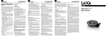
Figure 8: Block diagram of the series of files read for creating the model simulation package.
Figure 8 describes a series of steps which the xparser goes through to generate a simulation
package of the model. These steps have been explained as follows:
1. Reading in the model. The template Readmodel.tmpl provides these functions. This file
allows reading of the various tags in the model XML file.
2. Creating of dependency graph. The dot files are generated which are known as a series
of stategraph files. These diagrams display the description of the model, which order the
functions are called in and the different layers which denote the synchronisation points
among the agent functions due to communication dependencies.
24
3. Writing out the make file. This file contains the location of various files, like the libmboard
and more.
4. Writing out the xml.c file. This file contains functions for reading specific data variables
like static arrays, ints or doubles with in the agent memory. It also contain functions for
reading the data structures within the agent memory, for example:
read_mall_strategy(char * buffer, int * counter, mall_strategy *
tempdatatype)
The file also contains functions on reading the initial starting states file for the agent
memories. For this purpose it opens the ‘0.xml’ file and reads these values.
For parallel computation, an array is initialised for allowing round robin distribution of
the agents.
5. Writing out the main.c file. This is the main file which contains the complete xparser
functions being called. It reads in the number of iterations needed for the simulation, the
initial start states file, generate partitions for parallel computing and saves the iteration
data in progressive XML files. This file also performs additional functions, like
• traverses through the different agent states.
• checks conditions of the agent functions before calling them.
• calls the synchronisation code for the message boards. These are specific MB functions
which have been documented in the libmboard documentation.
• creates iterator for the messages.
• freeing agents when moving to next states.
• clears the message board at the end of the iteration.
• clean up.
6. Header.h file. This file provides the names being used in the simulation. For instance, the
xmachine agent memory, the states and the prototypes for the agent functions. Various
definitions for the messageboards like names of the iterators are also defined here, along
with prototypes for reading and writing various agent memory variables.
7. Writing the memory.c file. Memory.c file contains the actual function code of the functions
being used by the xparser. These are functions like free agents, or freeing messages by
calling MB Clear. The file contains various functions to initialise memory variables like
arrays or data structures. Functions for adding and freeing agents are also contained here.
8. Writing the rules.c file. Rules .c contains the rules being used in the model. For instance,
• For function conditions,
iteration loop%20==6 return 1 else return 0;
• Or for agent memory conditions,
a->learningwindow==0 return 1 else return 0;
9. Writing the low primes.c file. Low primes file defines the arrays which are used for partitioning of the data.
25
10. Writing the messageboards.c files. Messageboard.c is used for writing functions which allows access to the messageboard. For instance,
/*for adding messages*/
MB_AddMessage(b_messagename,&msg)
/*Rewinding an iterator*/ MB_Iterator_Rewind(i_mall_strategy_to_use)
/* getting a message*/
MB_Iterator_GetMessage(i_mall_strategy_to_use, (void**)&msg);
11. Writing the partitioning.c file. Partitioning.c file contains details for generating partitions
as geometric nodes and saves this data.
12. The timing.c returns the time it takes to run the code.
13. The Doxygen file writes out data about the model file.
Details of the message board functions are available at www.softeng.cse.clrc.ac.uk/
wiki/EURACE/MessageBoards/ImplementationNotes/API
11
XParser Versions
During the development process, the Xparser has gone through a series of development versions,
each being modified to include more features for making use easy for the modellers and increasing
efficiency.
Change logs for the different versions has been stored at the CcpForge repository for the developers. The XParser has a number of versions, with the latest version 0.15.13 which containing
the following additions:
• Checks added for environment variables and data type names.
• Fixes of writing out of output settings to command line.
• Merging of messages filters.
• stategraph colour version added.
• fix bug where import file not taken relative from 0.xml location.
• merge of sync filters.
• bug fix for nested filter rules.
• added ‘IN’ operator for filter rule.
• added random tag to message inputs.
• added sort tag to message inputs.
• parallel application can read pre-partitioned input files.
• added constant tag for agent memory variables.
• add option -f to xparser for final production run.
26
The current final version xparser 0.15.13 has been tested and used for various simulations
of the economic EURACE model and has been proved to be very stable and good for economic
modelling.
This version has thus been tagged to be released as FLAME version 1.0. Any future updates
to this version will be announced as new versions of FLAME.
12
Example Models
FLAME has a large community of modellers who are using the software for their own research.
Some of these models have been packaged up and distributed as example models to help future
FLAME users in doing their research. There are freely distributed with the XParser.
A
XML DTD
<!ELEMENT xmodel
(name,version,description,models?,environment?,agents,contexts?,messages?)>
<!ATTLIST xmodel version CDATA #REQUIRED>
<!ELEMENT models (model*)>
<!ELEMENT model (file,enabled)>
<!ELEMENT
<!ELEMENT
<!ELEMENT
<!ELEMENT
<!ELEMENT
<!ELEMENT
<!ELEMENT
<!ELEMENT
<!ELEMENT
environment (constants?,functionFiles?,timeUnits?,dataTypes?)>
dataTypes (dataType*)>
dataType (name,description,variables)>
variables (variable*)>
variable (type,name,description)>
constants (variable*)>
functionFiles (file*)>
timeUnits (timeUnit*)>
timeUnit (name,unit,period)>
<!ELEMENT agents (xagent*)>
<!ELEMENT xagent (name,description,memory?,roles?,functions?)>
<!ELEMENT memory (variable*)>
<!ELEMENT roles (role*)>
<!ELEMENT role (name,description,functions)>
<!ELEMENT functions (function*)>
<!ELEMENT function
(name,description,code?,currentState,nextState,condition?,inputs?,outputs?)>
<!ELEMENT condition ((not)|(lhs,op,rhs)|(time))>
<!ELEMENT not ((lhs,op,rhs)|(time))>
<!ELEMENT lhs ((not)|(lhs,op,rhs)|(value)|(time))>
<!ELEMENT rhs ((not)|(lhs,op,rhs)|(value)|(time))>
<!ELEMENT time (period,phase,duration?)>
<!ELEMENT inputs (input*)>
<!ELEMENT input (messageName,filter?,sort?)>
<!ELEMENT filter (lhs,op,rhs)>
<!ELEMENT outputs (output*)>
<!ELEMENT output (messageName)>
<!ELEMENT contexts (xcontext*)>
<!ELEMENT xcontext (name,description,messages)>
<!ELEMENT messages (message*)>
<!ELEMENT message (name,description,variables)>
27
<!ELEMENT
<!ELEMENT
<!ELEMENT
<!ELEMENT
<!ELEMENT
<!ELEMENT
<!ELEMENT
<!ELEMENT
<!ELEMENT
<!ELEMENT
<!ELEMENT
<!ELEMENT
<!ELEMENT
<!ELEMENT
<!ELEMENT
<!ELEMENT
<!ELEMENT
<!ELEMENT
code (#PCDATA)>
currentState (#PCDATA)>
description (#PCDATA)>
enabled (#PCDATA)>
file (#PCDATA)>
messageName (#PCDATA)>
name (#PCDATA)>
nextState (#PCDATA)>
op (#PCDATA)>
sort (#PCDATA)>
statement (#PCDATA)>
type (#PCDATA)>
value (#PCDATA)>
version (#PCDATA)>
unit (#PCDATA)>
period (#PCDATA)>
phase (#PCDATA)>
duration (#PCDATA)>
28