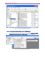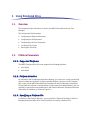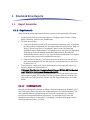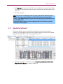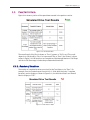
1
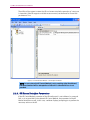
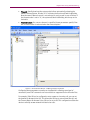
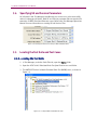
8100 Mobile Device System UMTS Simulated Drive User Manual Spirent 541 Industrial Way West Eatontown, NJ 07724 USA Email: [email protected] Web: http://www.spirent.com AMERICAS 1-800-SPIRENT • +1-818-676-2683 • [email protected] EUROPE AND THE MIDDLE EAST +44 (0) 1293 767979 • [email protected] ASIA AND THE PACIFIC +86-10-8518-2539 • [email protected] This manual applies to UMTS Simulated Drive Test Packs Version 1.6.5 or higher. Page Part Number: 71-006823, Version A0 Copyright © 2012 Spirent. All Rights Reserved. All of the company names and/or brand names and/or product names referred to in this document, in particular, the name “Spirent” and its logo device, are either registered trademarks or trademarks of Spirent plc and its subsidiaries, pending registration in accordance with relevant national laws. All other registered trademarks or trademarks are the property of their respective owners. The information contained in this document is subject to change without notice and does not represent a commitment on the part of Spirent. The information in this document is believed to be accurate and reliable; however, Spirent assumes no responsibility or liability for any errors or inaccuracies that may appear in the document. Table of Contents 1. Introduction ..................................................................................... 1 1.1. Overview ........................................................................................... 1 1.2. 1.3. Intended Audience ............................................................................. 1 Before You Get Started ....................................................................... 1 1.4. Security Information .......................................................................... 1 1.5. Accessing Documentation .................................................................. 3 1.5.1. Accessing Documentation from Windows Explorer .................................... 3 1.5.2. Accessing Documentation from Test Manager .......................................... 4 2. 3. Simulated Drive Description ............................................................. 5 2.1. 2.2. Overview ........................................................................................... 5 Description ........................................................................................ 5 2.3. Simulated Drive Testing ..................................................................... 5 Using Simulated Drive ...................................................................... 6 3.1. Overview ........................................................................................... 6 3.2. Platform Parameters .......................................................................... 6 3.2.1. Supported Platforms................................................................................ 6 3.2.2. Platform Selection ................................................................................... 6 3.2.3. Specifying a Platform File......................................................................... 6 3.3. UE Parameters ................................................................................... 7 3.3.1. UE Interface Parameters........................................................................... 7 3.3.2. UE Manual Interface Parameters .............................................................. 8 3.3.3. UE AT Interface Parameters .................................................................... 10 3.3.4. UE Spirent Data Client Parameters .......................................................... 11 3.4. 3.5. Specifying UE and Session Parameters ............................................. 14 Locating the Test Suite and Test Cases ............................................. 14 3.5.1. Locating the Test Suite ........................................................................... 14 3.5.2. Running the Test Suite ............................................................................ 15 4. Simulated Drive Reference.............................................................. 16 4.1. Overview ......................................................................................... 16 4.2. Test Suite Execution ......................................................................... 16 ii | UMTS Simulated Drive: User Manual 4.3. Simulated Drive Test Cases .............................................................. 18 4.3.1. Boston Drive Route Leg 1........................................................................ 18 4.3.2. Boston Drive Route Leg 2 ....................................................................... 18 4.3.3. Boston Drive Route Leg 4 ....................................................................... 18 4.3.4. New York, New Jersey Drive Route Leg 1.................................................. 18 4.3.5. New York, New Jersey Drive Route Leg 2 ................................................. 18 4.3.6. Seattle Drive Route Leg 1........................................................................ 19 4.3.7. Seattle Drive Route Leg 2 ....................................................................... 19 4.3.8. Seattle Drive Route Leg 3 ....................................................................... 19 4.4. Description of UMTS Simulated Drive Functionality............................ 20 4.4.1. Supported General Functions ................................................................. 21 4.4.2. Procedure Graph ................................................................................... 21 4.5. 5. Definition of Individual Test Case Results .......................................... 24 Simulated Drive Reports ................................................................. 25 5.1. Report Generation ............................................................................ 25 5.1.1. Requirements ........................................................................................ 25 5.2. Generating a Report ......................................................................... 29 5.3. Pass/Fail Criteria ............................................................................. 31 5.3.1. Number of Iterations ...............................................................................31 5.3.2. In Call Percentage .................................................................................. 32 5.3.3. Average Number of Call Drops ............................................................... 32 6. Appendix A: UE Configuration Procedure Samples .......................... 33 6.1. Overview ......................................................................................... 33 6.2. Common Procedures ........................................................................ 33 6.3. 6.4. Installing Auto-Answer App for Android Phones................................. 33 Specific UE Instructions.................................................................... 33 6.4.1. Samsung Focus(Windows7 Dialup Mode) ............................................... 33 6.4.2. Samsung SkyRocket (Android ICS Mode) ................................................ 34 6.4.3. Samsung Captivate (Android ICS Mode) ................................................. 34 6.4.4. HTC Inspire (Android ICS Mode) ............................................................. 35 6.4.5. HTC Aria (Android ICS Mode) .................................................................. 36 6.4.6. Motorola Atrix (Android ICS Mode) ......................................................... 36 6.4.7. Samsung Infuse 4G (Android ICS Mode) ................................................. 37 6.4.8. Blackberry Bold (Dialup Mode) .............................................................. 37 Table of Contents | iii 6.4.9. Samsung Galaxy S2 (Android ICS Mode) ................................................ 38 7. Appendix B: Frequently Asked Questions ....................................... 40 7.1. System Failures ............................................................................... 40 7.1.1. Fail to Remote Desktop into the Application Server ................................. 40 7.1.2. Tests Halt Due to “Autoset failure- 508” ................................................. 40 7.1.3. UE Fails Hard Handover 100% of the Time .............................................. 40 7.1.4. Fails to Start DEE Mode .......................................................................... 40 7.2. UE Failures....................................................................................... 40 7.2.1. UE Fails to Register After Installing Drivers and Connecting to Instruments 40 7.2.2. While making a data call in ICS mode, “Data call cannot be established since the UE IP address has not been assigned” message is displayed .. 41 7.2.3. UE device drive is failed to show up on client laptop-Windows Device manager................................................................................................ 41 7.2.4. SIM Not Provisioned .............................................................................. 41 7.3. Test Case Results ............................................................................. 41 7.3.1. Boston Leg 1 has more call drops than the other legs ............................. 41 7.3.2. Test Case says Other (Incomplete) and stops at step 2............................ 41 7.3.3. Test Case says Other (Incomplete) and stops at step 9............................ 42 7.3.4. Test Case says Other (Incomplete) and stops at step 10 .......................... 42 7.3.5. Test Case says Other (Incomplete) and stops at step 26.......................... 42 7.4. Test Manager Error Events ................................................................ 42 7.4.1. Failed to Initiate Transfer Because the PS RAB Session Could Not be Restarted ............................................................................................... 42 7.4.2. Start FTP Transfer - FTP Transfer Ended Unexpectedly ............................. 42 7.4.3. UE Failed to Respond to Page ................................................................. 42 7.4.4. Voice Call Not Active .............................................................................. 42 7.4.5. Compressed Mode: Physical Channel Reconfig Complete Not Received by the Network ........................................................................................... 43 7.4.6. Compressed Mode: Error in Sending Physical Channel Reconfig Message. 43 7.4.7. Setup Data Call Failed Because the RasDial Error.................................... 43 7.4.8. Data Client Download Error: HResult: 0xffffffff. Error Message: Download Transfer Timeout after 15 Seconds of No Data Transfer ........................... 43 7.4.9. RLC Unrecoverable Error/ RLC Reset ....................................................... 43 7.4.10. RF Loss .................................................................................................. 43 iv | UMTS Simulated Drive: User Manual 7.4.11. The .NET Method ‘Download Transfer’ threw an exception. The Process Cannot Access the File “X”...................................................................... 44 7.4.12. Release 3G Data Call: Data Call Not Terminated/ Timeout Waiting for ReleaseCall in AirAccessHS .................................................................... 44 1. Introduction 1.1. Overview This manual provides information on the performance testing features of the UMTS Simulated Drive Test Packs (SDT). You will become familiar with the Suites, Test Cases, and setting up UMTS Simulated Drive testing scenarios in the Test Manager environment by following the step-by-step procedures and Test Reference documentation. 1.2. Intended Audience This manual is intended for those who have a working knowledge of wireless communication equipment, and are familiar with the automated testing of mobile devices. It is assumed that you are familiar with the Test Manager GUI environment. If you are unfamiliar with Test Manager, refer to the Test Manager User Manual before proceeding. 1.3. Before You Get Started Before getting started, install all software and power-on the test system. The controller PC is shipped with the Test Manager Test Executive software and UMTS Simulated Drive Test Packs installed. 1.4. Security Information UMTS Simulated Drive is shipped with the appropriate dongle and software/hardware security passwords configured. To verify the security information: 1. Open Test Manager and select Help>About. The About Test Manager window displays, as shown in Figure 1-1. 2 | UMTS Simulated Drive: User Manual Figure 1-1: About Test Manager Window 2. Select the Passwords tab. 3. Under Installed Features, confirm the UMTS Simulated Drive Test Packs are installed, as shown in Figure 1-2. Chapter One: Introduction | 3 Figure 1-2: About Test Manager Window – Installed Features Password authentication is a prerequisite to running tests provided by this module. Passwords are tied to security information provided by the USB hard-lock dongle that comes with the module installation. If you have any questions or concerns, contact Spirent Technical Support at support.spirent.com, or by phone at 1-800-SPIRENT. 1.5. Accessing Documentation There are two ways to access this document from the Controller PC: 1. Windows Explorer 2. Test Manager These methods are described in detail in the sections below. 1.5.1. Accessing Documentation from Windows Explorer Access this Manual offline by navigating to C:\Program Files\Spirent Communications\Test Manager\Modules\UMTS Simulated Drive\Simulated Drive User Manual.pdf using Windows Explorer, as shown in Figure 1-3. 4 | UMTS Simulated Drive: User Manual Figure 1-3: Accessing the Manual from Windows Explorer 1.5.2. Accessing Documentation from Test Manager Access this Manual from the Test Manager menu by selecting: Help>Modules>UMTS Simulated Drive>Simulated Drive User Manual.pdf, as shown in Figure 1-4. Figure 1-4: Accessing the Manual from Test Manager 2. Simulated Drive Description 2.1. Overview This chapter provides a high-level overview of the key components necessary to configure and use UMTS Simulated Drive. 2.2. Description UMTS Simulated Drive is an integrated software component that allows you to connect a device and analyze its behavior and performance against the same RF conditions as if it was being drive tested in the corresponding city routes. All routes are run under the RF conditions reported for that route with the standard Network settings described in the sections corresponding to the individual test case for the route. The UMTS Simulated Drive Test Pack leverages the state machine implementation of the network emulator component to handle rapidly changing RF conditions and asynchronous events from the UE to simulate a drive route through a wireless network. The UMTS Simulated Drive test cases run with the Test Manager software. This provides an easy way to automate test sessions with analysis and reporting capabilities. 2.3. Simulated Drive Testing UMTS Simulated Drive offers a complete platform to evaluate UE behavior and performance similar to that of a live network. The platform plays back recorded RF conditions from the field in an emulated environment to allow a UE to be tested for a drive route in a lab environment rather than having to drive the actual route. This allows carriers to gain a realistic view of how a UE performs on a live network without requiring them to leave the lab. 3. Using Simulated Drive 3.1. Overview This chapter provides information on how to use UMTS Simulated Drive from Test Manager. This includes the following steps: 3.2. • Configuring the Platform Parameters • Configuring the UE Parameters • Configuring the Session Parameters • Locating the Test Cases • Running the Test Suite Platform Parameters 3.2.1. Supported Platforms The UMTS Simulated Drive Test suite supports the following platforms: • 8100-A304 • 8100-A604 3.2.2. Platform Selection As indicated in the Test Manager Operations Manual, you cannot run a suite successfully unless it undergoes validation using the specified Platform, Session and UE Parameter files. In the case of UMTS Simulated Drive installed with the Test Manager, the platform file used with this module is already selected. In the event of multiple platforms, you are required to specify the correct platform from the Platform Selection dropdown field in the Execute Session window, as shown in Figure 3-1. 3.2.3. Specifying a Platform File In addition to the Platform Selection, you must specify a Platform File. Refer to the Test Manager Operations Manual for more information on creating a Platform File. Chapter Three: Using Simulated Drive | 7 Figure 3-1: Execute Session Window – Platform Selection for UMTS Simulated Drive 3.3. UE Parameters The level of automation and reliability of the system is heavily dependent on the ability of the system to control the UE. UE parameters are configured to facilitate these activities. 3.3.1. UE Interface Parameters The UE interface parameters specify how the UE is controlled during test case execution. The options for the UE Control Method are: • Manual: The system prompts the operator to perform actions on the UE. (This is the least desirable with regards to running Simulated Drive Tests due to the asynchronous events from the UE’s and the length of the tests being performed.) • AT: The system issues the specified AT commands to control the UE. • Custom: (Advanced) Allows custom UE control. If Custom is selected, the UE Control Sequence File parameter specifies the Control Sequence file used by the system. 8 | UMTS Simulated Drive: User Manual The ability of the system to return the UE to a known state before execution of a test case is important. If the UE supports a reliable reset command, set the Reset for Ensure Idle parameter to True. Figure 3-2: UE Parameters Window – UE Interface Parameters NOTE: In cases where the UE Control Method is set to anything other than Manual, the Manual method will be attempted as a fallback if a command fails or is not provided. 3.3.2. UE Manual Interface Parameters If the UE Control Method parameter of the UE Interface tab is set to Manual, a command fails, or is not provided by the selected UE Control Method, the parameters of the UE Manual Interface are used. In this case, a window displays prompting you to perform the necessary action on the UE. Chapter Three: Using Simulated Drive | 9 • Timeout: Specify how long the system waits before automatically selecting the defined Timeout Button. A value of “0” indicates the function will wait indefinitely. Note that even if Manual control is not selected, it may be used in case of failure. If the timeout value is set to “0”, the system will wait indefinitely, which may not be desirable. • Timeout Button: If a non-zero timeout is specified, these parameters specify if the OK or Cancel button is selected when the timeout expires. Figure 3-3: UE Parameters Window – UE Manual Interface Parameters Configuring these parameters correctly can be effective in allowing some level of automation; even if AT commands are not available or supported for the UE under Test. For example, if the UE can be configured to auto-answer an incoming call, you can set the timeout for Answer Voice Call. This allows the UE time to auto-answer the call, and the Timeout Button for Answer Voice Call can be set to OK. This configuration allows the device to reliably answer network-initiated voice calls. 10 | UMTS Simulated Drive: User Manual 3.3.3. UE AT Interface Parameters If the UE reliably supports AT commands, AT control can be very useful. The UE is connected to the Data Client PC for AT control after the manufacturer's driver software is installed. The following parameters are provided: • Port: Set this parameter to the port on the Data Client PC assigned to the modem when the UE is connected. • Commands: Configure the available AT command strings. • Bits Per Second: Configure the baud rate. • Data Bits: Configure the number of data bits. • Parity: Configure the parity. • Stop Bits: Configure the stop bits. • Flow Control: Configure the flow control. • Enable DTR: Enables Data Terminal Ready Signaling. • Enable RTS: Enables Request To Send Signaling. • New Line: Specifies the new line terminator to use. • Test AT Commands: Use this wizard to test AT commands to check if the UE responds correctly and reliably before testing. Chapter Three: Using Simulated Drive | 11 Figure 3-4: UE Parameters Window – UE AT Interface Parameters NOTE: There is great variability in the AT commands supported by UE vendors and how reliably the work. Experimentation may be necessary to determine the best settings. 3.3.4. UE Spirent Data Client Parameters In general, there are two connection modes the UE uses to connect to the data client while running Simulated Drive: 1. Dial-up Networking (DN) 2. Internet Connection Sharing (ICS) These modes are described in detail in the following sections. 12 | UMTS Simulated Drive: User Manual 3.3.4.1 Dial-up Networking When in Dial-up Networking Mode (default), the UE connects to the client laptop via USB as a standard modem. On the client laptop under network connections the Test Drive Data Connection should have Standard Modem chosen with the corresponding correct com port that is also selected for the AT commands specified above. Figure 3-5: UE Spirent Data Client Parameters – Dial Up Networking 3.3.4.2 Internet Connection Sharing Most new phones are smart phones which require USB tethering; this requires you to utilize Internet Connection Sharing Mode on the client laptop. To set up the UE file to use ICS Mode: 1. Set the Connection Mode to Internet Connection Sharing. 2. Set the MTU Size to 1410. Chapter Three: Using Simulated Drive | 13 Figure 3-6: UE Spirent Data Client Parameters – Dial Up Networking Figure 3-7: UE Spirent Data Client Parameters – Dial Up Networking 3. For the Connection window, select Disabled from the drop-down menu. If this option is left enabled for any period of time it prevents the continuous run required for Simulated Drive testing and may affect performance and results. 4. Set the Device Interface Name: a. Enable USB Tethering on the UE that is connected to the client laptop. b. Make sure the name for the Local Area Connection Device Name established by the device in the Network Connections window on the client laptop matches the Device Interface Name that you set in the UE file. Capitalization and Spaces all need to be exact. 14 | UMTS Simulated Drive: User Manual 3.4. Specifying UE and Session Parameters As indicated in the Test Manager User Manual, you cannot run a suite successfully unless it undergoes validation. Both UE and Session parameter files are required for execution of UMTS Simulated Drive test cases. Refer to the Test Manager Operations Manual for more information on creating UE and Session Files. Figure 3-8: Selecting UE and Session Files for UMTS Simulated Drive 3.5. Locating the Test Suite and Test Cases 3.5.1. Locating the Test Suite 1. In Test Manager, under the Suite Files tab, open the Suites folder. 2. Open the AT&T 16815 Simulated Drive Test Specification vx.x.x subfolder. 3. The UMTS SDT Suite is labeled Simulated Drive Test (MRAB) vx.x.x, as shown in Figure 3-9. Figure 3-9: Locating UMTS Simulated Drive Suite Chapter Three: Using Simulated Drive | 15 3.5.2. Running the Test Suite To run the test suite: 1. In Test Manager, open the test suite from the Suite Files tab of the File Cabinet as explained in section 3.4 NOTE: Each Test Case in a pre-defined Suite has test case parameters configured to support the test definition. The Test Cases for UMTS Simulated Drive should not be altered. 2. From the Test Manager menu, select Execute>Start Session>Run All Test Cases to start executing the entire Test Suite. You also have the option of executing only the currently selected test case. The Execute Session window displays. 3. To run the UMTS Simulated Drive Test Suite, ensure that you have the correct platform selected. If you want to run the test with the default fields as shown in the Execute Session window, skip steps 5 and 6. For more information on configuring Session and UE parameter files, refer to Section 3.2. 4. If desired, specify the Tester Name, UE Manufacturer, and UE Model. These fields display on all reports you create based on the results of this session. 5. Click OK to begin validation. If successful, the test session begins, as shown in Figure 3-10. Figure 3-10: Test Session in Progress 4. Simulated Drive Reference 4.1. Overview This chapter provides detailed descriptions of the UMTS Simulated Drive test cases. It includes the algorithms implemented during test execution. 4.2. Test Suite Execution This section describes the sequence of operations performed during the execution of the SDT suites from Test Manager. Chapter Four: Reference | 17 Figure 4-1: Test Suite Execution Flowchart 18 | UMTS Simulated Drive: User Manual 4.3. Simulated Drive Test Cases This section describes the Test Cases and what may be different or unique to the individual test case. Functionality that is common to all is described in the next section. 4.3.1. Boston Drive Route Leg 1 • Test case duration is approximately 60 minutes start to finish. • 3 Full WCDMA Cells Single Frequency • 50% In Call Percentage required for statistical verification. • The RF conditions presented in this route are more difficult than any of the other routes. 4.3.2. Boston Drive Route Leg 2 • Test case duration is approximately 60 minutes start to finish. • 3 Full WCDMA Cells Single Frequency • 65% In Call Percentage required for statistical verification. 4.3.3. Boston Drive Route Leg 4 • Test case duration is approximately 50 minutes start to finish. • 3 Full WCDMA Cells Single Frequency • 65% In Call Percentage required for statistical verification. 4.3.4. New York, New Jersey Drive Route Leg 1 • Test case duration is approximately 15 minutes start to finish. • 3 Full WCDMA Cells Two Frequencies • 65% In Call Percentage required for statistical verification. • Hard Handover possible on this route 4.3.5. New York, New Jersey Drive Route Leg 2 • Test case duration is approximately 70 minutes start to finish. • 3 Full WCDMA Cells Single Frequency • 65% In Call Percentage required for statistical verification. Chapter Four: Reference | 19 4.3.6. Seattle Drive Route Leg 1 • Test case duration is approximately 50 minutes start to finish. • 3 Full WCDMA Cells Single Frequency • 65% In Call Percentage required for statistical verification. • 1 GSM Cell at a constant -80 dBm (Inter-rat handover possible but not expected) 4.3.7. Seattle Drive Route Leg 2 • Test case duration is approximately 20 minutes start to finish. • 3 Full WCDMA Cells Two Frequencies • 65% In Call Percentage required for statistical verification. • Hard Handover possible on this route 4.3.8. Seattle Drive Route Leg 3 • Test case duration is approximately 30 minutes start to finish. • 3 Full WCDMA Cells Single Frequency • 65% In Call Percentage required for statistical verification. • 1 GSM Cell at a constant -80 dBm (Inter-rat handover possible but not expected) 20 | UMTS Simulated Drive: User Manual 4.4. Description of UMTS Simulated Drive Functionality The functionality used in the Simulated Drive Test Cases is a sub-set of the overall capability of the UMTS 8100 platforms. However, within the context of Simulated Drive the functionality that is supported is fully integrated and works together seamlessly. The main differentiator between Simulated Drive and other Spirent 8100 Platform products is that Simulated Drive leverages state machine functionality to REACT to real world real time events and provide an analysis of the UE’s behavior rather than “forcing” scenarios and expecting a well-defined outcome by the UE. Because this test is reactive and provides only analysis call drops are expected. The frequency of call drops, UE recovery capability, etc. are analyzed collated and averaged across all routes to provide and accurate analysis of the UE’s performance. Pass and Fail criteria are described in the reporting section of this document. Part of the Simulated Drive functionality is pseudo-random FTP file transfers to emulate a data push to the UE (similar to an email update etc.). Because this data push is randomized a rerun of the exact same test case with the exact same UE may produce different results. This mostly comes into play during bad RF conditions. If the UE is only responsible for handovers to keep the voice call active during the “bad RF conditions” it may make it through without dropping the call. However, if one of the data transfers occurs in conjunction with the handovers needed etc. and RLC retransmission occurs we may have to drop the call due to RLC Unrecoverable error, RLC reset, or RLC reset due to RLC retransmission exhaustion. This explains why some results may be different even with the same UE on the same test case. Simulated Drive runs may also differ due to rapidly changing RF Conditions. While in most cases soft handovers etc. will be relatively consistent, there may be cases when the UE attempts to register and is also performing cell reselection which will force another registration. Also the network can only process one handover request at a time. Therefore if another request comes in while a previous one is being processed it must be ignored until the first request is complete. This may cause the UE to lose the best cell due to the rapidly changing RF conditions which can result in a call drop. This is expected and accounted for in the number of call drops expected. SDT Inter-RAT handover to GSM is supported only in one-way direction. Data RAB is dropped before handing over to the GSM network. Only voice RAB hands over to GSM. GSM>WCDMA inter-RAT handovers are not supported. After successful completion of inter-RAT handover, the voice call is dropped and drive simulation continues after the UE reselects the WCDMA network. SDT requires the UE to be tethered to enable ICS mode. Proper UE drivers are also required to install NIC interface to enable tethering. If a UE does not support tethering, a non-preferred dial-up mode can be used. Chapter Four: Reference | 21 4.4.1. Supported General Functions The following functionality is fully integrated and supported in conjunction with all the features listed for SDT. • Voice + Data (R99 UL / HSDPA DL) • HSDPA Serving Cell Change • Multi-RAB 3-Way Soft Handover • Inter-Frequency Hard Handover (3G->3G Voice and Data) • Inter-RAT Hard Handover (3G<->2G Voice Only) • Compressed Mode • Voice Playback • Authentication and Ciphering • Up to 3 Full WCDMA Cells plus 1 Full GSM Cell • Up to 2 Full WCDMA Cells on one frequency and 1 Full WCDMA Cell on a different frequency • Rate Shift to/from R99 UL / HSDPA DL to/from R99 UL / R99 DL • Voice + Data dormancy to PS Idle/RAB Release (Dormancy) • CS + PS Supplementary Service with multi-RAB call • Pseudo Randomized FTP Transfers • Pre-R8 SCRI Handling 4.4.2. Procedure Graph For the purposes of the explanations in this section: • Horizontal “wavy” lines on the graph are referred to as the RF Level / Cell Activity Lines. • Vertical dotted lines are Event Lines. • Vertical Solid Lines are Activity lines. 22 | UMTS Simulated Drive: User Manual Figure 4-2: Procedure Graph The events and actions that are printed on the graph may not be the EXACT time of the occurrence of the event or action. This is due to artificial latency in the messaging between the network emulation and the PC notifying the PC that action is complete or the event received and when it can be printed on the graph. Some things may appear slightly out of order etc. However, this is a very good representation of the activity and a reasonable timeline of when events occur. 4.4.2.1 RF Level Lines / Cell Activity Lines The Horizontal lines on the Procedure Graph represent the different cells that are configured for the Drive Route. The height of the horizontal line represents the cell’s power level at that point in time. If the horizontal line is solid then that cell is part of the current active set (in soft handover). If the horizontal line is dotted then the cell is NOT part of the current active set. 4.4.2.2 Event Lines Every event that is received from the UE is logged in the Procedure graph and is shown with a dotted vertical line. Not every event is acted on. If the network is currently acting on an event it is unable to process the next event until that action is complete. In order for the network to remain current to the UE events are discarded until the current action is complete and then the next event received from the UE will be processed (The only exception to this rule is Compressed Mode). All of the following events are supported by the system. This does not mean all events will happen on every leg or on any leg in particular. Chapter Four: Reference | 23 • Event 1a: Add Cell to Soft Handover • Event 1b: Delete Cell from Soft Handover • Event 1d: Update Best Cell (May result in Physical Channel Reconfiguration to change the HSDPA Serving Cell) If not currently in a HSDPA call this event is handled internally and will not show on the procedure graph. • Event 2b: Hard Handover • Event 2d: Enable Compressed Mode (In the case of this event if the network is busy processing a different event, Event 2d will be saved and retried until either successful, Call Drop, or Event 2f is received) • Event 2f: Disable Compressed Mode • Event 3a: Inter-RAT Handover 4.4.2.3 Action Lines Events that are processed and actually take place in the state machine are referred to as Actions. Other significant actions may also occur such as FTP transfers, Call Drops, etc. All of these actions are denoted with solid vertical lines in the procedure graph and labeled accordingly. Successful Actions • Add Soft Handover: Action completed after an Event 1a. • Delete Soft Handover: Action completed after an Event 1b. • Start Compressed Mode Postponed: Action postponed due to Event 2d received and another action is currently being processed. • Start Compressed Mode: Action completed after an Event 2d OR due to a Start Compressed Mode Postponed retry. • Stop Compressed Mode Postponed: Action postponed due to Event 2f received and another action is currently being processed. • Stop Compressed Mode: Action completed after an Event 2f OR due to a Stop Compressed Mode Postponed retry. • Start FTP Transfer: Start one of the Pseudo Randomized FTP Transfers. • Hard Handover: Hard Handover to another frequency WCDMA Cell successful. Failure Actions Most Failures listed below are usually a result of rapidly changing RF conditions where the request comes in a little too late. • Call Drop: Current Call Dropped (common causes are described in the next section). • Add Soft Handover Failure: Attempt to add cell to soft handover failed. • Delete Soft Handover Failure: Attempt to delete cell from soft handover failed. • Start Compressed Mode Failure: Attempt to put the UE into compressed mode failed. 24 | UMTS Simulated Drive: User Manual • Stop Compressed Mode Failure: Attempt to bring the UE out of compressed mode failed. • Hard Handover Failure: Hard Handover to another frequency failed. 4.4.2.4 Common Causes for Call Drops All of the Call Drop causes below are expected and considered “normal” behavior. The frequency of the drops is what determines whether or not the behavior of the UE is acceptable. 4.5. • RF Loss: RF Loss on one of the cells before it can be deleted from the active set causes the cells to go out of sync and drop the call. • RLC Reset: Due to changing RF conditions the UE may go into RLC retransmission. In this case, the RF conditions may recover and the call stays up. The first attempt moves the receive window in an attempt to keep the call up. However, if the UE requests RLC Reset or the network exhausts all retransmissions, a RLC Reset occurs and the call is dropped. • UE Latency in Add/Delete/Update Requests: At times during runs the RF Conditions between cells change so rapidly that by the time a cell is added it immediately needs to be deleted which may cause sync loss. Also the RF may change radically before the request can be sent in time from the UE for the network to react. This may lead to a cell not being added to SHO in time resulting in eventual RF loss and Call drop. Definition of Individual Test Case Results Individual Test Cases have the possibility of reporting any one of the 3 result values listed below. Although these result values give an indication of whether or not the phone is having difficulty with a particular Drive Route they do not represent the overall Pass or Fail of the Test Suite. As described in the next section the Pass/Fail criteria is determined through analysis of the data from ALL routes combined. • Other (Complete): Test Case ran to completion with adequate “In Call Percentage” that is considered statistically relevant and usable in the reports generated. • Other (Incomplete): Any failure for any reason is considered Incomplete. This includes but is not limited to: “In Call Percentage” was below the required threshold to be considered statistically relevant. UE Failed to register. UE Failed to tether. UE Failed to respond to page requests. UE reselection during registration due to rapidly changing RF conditions. Other (Rerun): This is a test that is rerun due to a previous “Incomplete” run. 5. Simulated Drive Reports 5.1. Report Generation 5.1.1. Requirements These following are the requirements that must be met before generating a SD report: • The test should show all 8 test cases/legs as “Complete” under “Status” column within “Summary” section of the Test Manager. • For Other (Incomplete) - • If the test had exited out due to UE not registering, a tethering issue, or hardware problems with test equipment, the Test step number should be low (i.e. Step 2 or Step 9). The test may also be “Incomplete” due to low In Call Percentage (explained later in the document). This usually stops at step 26 or 29. Regardless of the reason for the Incomplete Status the Simulated Drive Test will then automatically rerun the test once. So, If any of the test results show “Incomplete” as the test status, they are incomplete after one rerun. If the test fails on the retry, you need to rerun the iterations as a new test and then combine the previous and new tests into a consolidated test as described in Section 5.1.1.1. There should be “results.mdb” file in the folder that contains the test results. For example, the Results Path Selection is: C:\Program Files\Spirent Communications\AirAccess WCDMA-HS\Test Session Logs\ \Sim Drive Development\Samsung Galaxy S2 In this case, the Samsung Galaxy S2 folder contains a subfolder with the test case name containing eight (all Complete first time) to sixteen (all rerun) subfolders for each of the test cases/iterations, Results.mdb file, Spreadsheet report, and other folders. 5.1.1.1 Combining Results Normally, all the legs will complete and there is no need to rerun tests. However, out of the 8 Test cases, some of the test cases might show status as “other(Incomplete”) not due to genuine lower In-Call percentage but due to UE not registering, or Internet Connection Sharing establishment problems etc. So, we might want to rerun the problematic test cases as a new test(s). For example, consider the following run from Samsung Captivate (2012 5 11 1226). 26 | UMTS Simulated Drive: User Manual Figure 5-1: Test Run with Test 6 Incomplete As shown in this example, out of eight Test cases, Test case 6 is “Incomplete” even after one automatic retry as UE failed to register. A new test is created (2012 05 13 1722) which runs the failed Test case six times, as shown in Figure 5-2. Figure 5-2: New Test with 6 Runs of the Previous Incomplete Run The next step is to create a consolidated test containing 8 test cases. The steps are shown below: 1. Open Test Manager and select Result Files from the File Cabinet. 2. Select the 2012 5 11 1226 and 2012 05 13 1722 folders. Right-click and select Combine Results from the menu, as shown in Figure 5-3. Chapter Five: Reports | 27 Figure 5-3: Combining Results 3. The Results Combiner window displays, as shown in Figure 5-4. Under Source, select the desired test cases. For example, select Test case 1-5 from 2012 5 11 1226 and click the arrow button to move them to Constructed window area. 4. Select test case 1 from 2012 05 13 1722 and repeat, as shown in Figure 5-5. This test case corresponds to the Test case 6 (Seattle Drive Leg-1, which can be found under the Detail section) of 2012 5 11 1226. 5. Repeat the procedure for remaining two test cases 7 and 8 of test 2012 5 11 1226. The Constructed window now displays eight test cases, as shown in Figure 5-6. The test cases have been combined and the resulting eight test cases correspond to the original eight in terms of Boston, New York, and Seattle routes. 28 | UMTS Simulated Drive: User Manual Figure 5-4: Selecting Test 1-5 from 2012 5 11 1226 Figure 5-5: Selecting Test -1 from 2012 05 13 1722 Figure 5-6: Selecting Test 7-8 from 2012 5 11 1226 Chapter Five: Reports | 29 6. Click Save As and save the results file in the same folder as the combined test files. The Combiner automatically creates a new consolidated test with the updated date and time. 7. Close the Combiner. NOTE: The process of combining results may take a few minutes depending on the number of test cases and where they are located. If Test Manager appears to be “frozen”, open Windows Explorer and go to the directory previously specified to save the combined results. You should be able to observe activity copying the files to this folder to verify the combining is still in progress. 5.2. Generating a Report This section explains how to create the excel report from the 8 test cases we just created. This would apply to the test cases obtained standalone on first run or created through combining various tests as in the previous section. Figure 5-7: Combined Tests 1. Right click on 2012 05 14 0523 and select Create Report>Simulated Drive Test Report>Detailed Report, as shown in Figure 5-8. 30 | UMTS Simulated Drive: User Manual Figure 5-8: Creating a Spreadsheet from Combined Tests 2. The final consolidated report is shown in Figure 5-9. Figure 5-9: Consolidated Report Chapter Five: Reports | 31 5.3. Pass/Fail Criteria Figure 5-10 shows a portion of the spreadsheet created in the previous section. Figure 5-10: SDT Results Table The overall result of the Test is shown as “Pass” in green or “Fail” in red. This result depends on (all should be “Pass” to have overall Test as “Pass”) the “Status” column values in Figure 5-10. All iterations are Complete and the Average Number of Call Drops and the In Call Percentage is below the pre-determined threshold. 5.3.1. Number of Iterations The number of complete iterations must be 8 for the Test Status to be “Pass”. For example, if we had created report from 2012 5 11 1226 which had only 7 complete iterations, results display as shown in Figure 5-11; the individual Status and Overall Results display as “Fail”. Figure 5-11: Fail Status in Table 32 | UMTS Simulated Drive: User Manual 5.3.2. In Call Percentage The parameter which captures the essence of the test results is In Call Percentage. Even though average number of call drops is used to determine the test result, In Call percentage must be used to determine if the Call Drop Number is statistically relevant. This is important for the Simulated Drive Test due to rapidly fading conditions under which UE operates leading to call drops and potential failure to re-establish the call. For example, in the Boston Route Leg 1, in about 50 minute test, there may be a legitimate call drop after 10 minutes, and we may not be able to set the call back up for the remaining 40 minutes. We report the single call drop in this iteration (which is very good), however in reality, out of the 50 minute test, the UE was in call for only 10 minutes. A better representation of the test is the percentage of time UE stayed in Call, which is In Call Percentage. For this example, it would be 20%(10/50). Therefore in order for the Call Drop number in the test to be considered statistically relevant it must also meet the In Call Percentage criteria. 5.3.3. Average Number of Call Drops This is the average of the Number of Voice call Drops, averaged over 8 iterations. Figure 5-12: Basic Voice Call Statistics Table In the above table, Average number of call drops is 4.6, which is the average of 8 values of column named “Num Call Drops” .This is also shown as the value under “average number of call drops” in the “Simulated Drive Test Results” table. There are other columns in the table that deserve attention. Let us consider iteration1 corresponding to Boston Drive Route Leg1. Here, an attempt was made to setup voice call 35 times, and 15 of those attempts were successful. In these successful attempts, the call dropped 14 times. 6. Appendix A: UE Configuration Procedure Samples 6.1. Overview The following are a few examples with various UE’s. User should download the latest UE software’s and use the latest firmware as it was observed that doing so does improve the In call percentage and give better results 6.2. Common Procedures Wifi, Bluetooth, GPS, Location Services should be off. Create UE files for the ICS mode or Dial-Up mode as per the method described earlier in Chapter 3. 6.3. Installing Auto-Answer App for Android Phones 1. Download Google AutoAnswer.apk with GPL license and place it in the Client Laptop under: C:\Program Files\Spirent Communications\Spirent Data Client\. 2. Enable USB debugging by selecting Settings>Applications>Development>USB Debugging: On. 3. Execute on command prompt to make sure that android USB device shows up with device number and a message “1 device connected”(by typing the command “adb devices”). If not, make sure that step#1 is executed. C:\Program Files\Spirent Communications\Spirent Data Client\ adb devices 4. Execute on command prompt: C:\Program Files\Spirent Communications\Spirent Data Client\ adb install AutoAnswer.apk 6.4. Specific UE Instructions 6.4.1. Samsung Focus(Windows7 Dialup Mode) 1. Software/Drivers: Samsung Kies 2. Simcard: Spirent Sim 3. Phone Settings: Default (No Change) 4. Tethering Settings: Default (No Change) 34 | UMTS Simulated Drive: User Manual 5. APN Settings: Default (No Change) 6. Special Steps: Make sure that the Modem Com port in Client Laptop for this UE matches the COM Port in the UE file. 7. Create a Dial up Connection with the following settings: a. Connection Name: TestDrive Data Connection b. Username: test c. Password: test d. Phone Number: *99# e. Set Com Port as the default connection in the device manager when the BlackBerry is connected. 6.4.2. Samsung SkyRocket (Android ICS Mode) 1. Software/Drivers: Samsung Kies. 2. Simcard: ATT Sim and Spirent PLMN. 3. Phone Settings: a. Settings->Wireless & Networks -> Mobile Networks -> Data Roaming: On b. Settings->Wireless & Networks -> Mobile Networks -> Use Packet Data: On 4. Automatic Call Answer: Enabled 5. Run Test Manager and pause the test when the “wait 60 seconds for registration” message displays. 6. Put UE in flight mode. If the UE does not register, reboot the UE and make sure it makes a data call automatically. 7. Tethering: Settings->Wireless & Networks -> Tethering and portable Hotspot -> USB tethering: On 8. Make sure that device shows as Samsung Mobile USB remote NDIS Network device (data client tab in UE file). This should match the settings under WIFI connections on client laptop. If it does not, change the UE file name, save the file and stop the test. Rerun the tests repeating steps 5, 6, and 7. 6.4.3. Samsung Captivate (Android ICS Mode) 1. Software/Drivers: Samsung Kies 2. Simcard: ATT Sim and Spirent PLMN 3. Phone Settings: a. On the UE, dial *#9090# Chapter Six: Appendix A | 35 b. Service Model-> Log via USB c. Dial *#7284# d. Phone Utility -> UART: modem and USB:PDA e. Switch off and on the UE, connect to client laptop and verify that it shows as Samsung Android USB modem (or #1,2, etc.) under device manager->modem. f. Settings->Wireless & Networks -> Mobile Networks -> Data Roaming: On g. Settings->Wireless & Networks -> Mobile Networks -> Use Packet Data: On h. Special Steps: Make sure that the Modem Com ports in Client Laptop for this UE matches the COM Port in the UE file. 4. Automatic Call Answer: Enabled. 5. Run Test Manager and pause the test when the “wait 60 seconds for registration” message displays. 6. Put UE in flight mode. If the UE does not register, reboot the UE and make sure it makes a data call automatically. 7. Enable Tethering. 8. Make sure that the device displays as “Samsung Android USB remote NDIS Network device” under the Data Client tab in UE file. It should match the settings under the WIFI connections on client laptop. If it does not, change the UE file name, save the file and stop the test. Rerun the tests repeating steps 5, 6, and 7. 6.4.4. HTC Inspire (Android ICS Mode) 1. Software/Drivers: HTC Sync 2. Simcard: ATT Sim and Spirent PLMN 3. Phone Settings: a. Settings>Wireless & Networks >Mobile Networks> Access Point Names >Spirent >``MCC: 001 b. Settings->Wireless & Networks -> Mobile Networks> Access Point Names -> Spirent -> MNC: 01 c. Settings->Wireless & Networks -> Mobile Networks -> Data Roaming: On d. Settings->Wireless & Networks -> Mobile Networks -> Enable always-on mobile data: On NOTE: If you connect to the client laptop, it is possible that no information will display under the device manager modem. 4. Automatic Call Answer: Enabled 5. Run Test Manager and pause the test when the “wait 60 seconds for registration” message displays. 36 | UMTS Simulated Drive: User Manual 6. Put UE in flight mode. If the UE does not register, reboot the UE and make sure it makes a data call automatically. 7. Settings->Wireless & Networks -> Mobile Network: On 8. Settings->Wireless & Networks -> USB Tethering: On 9. Make sure that device displays as “HTC Remote NDI based device” under the Data Client tab in UE file. It should match the settings under WIFI connections on the client laptop. If it does not, change the UE file name, save the file and stop the test. Rerun the tests repeating steps 5, 6, 7, and 8. 6.4.5. HTC Aria (Android ICS Mode) 1. Software/Drivers: HTC Sync 2. Simcard: ATT Sim and Spirent PLMN 3. Phone Settings: a. Settings->Development->Allow Mock Locations: On b. Settings->Wireless & Networks -> Mobile Network: On c. Settings->Wireless & Networks -> Mobile Networks -> Data Enabled: On d. Settings->Wireless & Networks -> Mobile Networks -> Data Roaming: On e. Settings->Wireless & Networks -> Mobile Networks -> Enable always on Mobile Data: On 4. Automatic Call Answer: Enabled 5. Run Test Manager and pause the test when the “wait 60 seconds for registration” message displays. 6. Put UE in flight mode. If the UE does not register, reboot the UE and make sure it makes a data call automatically. 7. Settings->Wireless & Networks -> USB Tethering: On 8. Make sure that the device displays as “HTC Remote NDIS based device” under the Data Client tab in UE file. It should match the settings under WIFI connections on the client laptop. If it does not, change the UE file name, save the file and stop the test. Rerun the tests repeating steps 5, 6, and 7. 6.4.6. Motorola Atrix (Android ICS Mode) 1. Software/Drivers: MotoHelper 2. Simcard: ATT Sim and Spirent PLMN 3. Automatic Call Answer: Enabled Chapter Six: Appendix A | 37 4. Run Test Manager and pause the test when the “wait 60 seconds for registration” message displays. 5. Put UE in flight mode. If the UE does not register, reboot the UE and make sure it makes a data call automatically. 6. Tethering: Settings->Wireless & Networks -> Tethering and Mobile Hotspot -> USB tethering: On 7. Make sure that the device displays as “Motorola USB remote NDIS Network device” under the Data Client tab in UE file. It should match the settings under WIFI Connections on the client laptop. If it does not, change the UE file name, save the file and stop the test. Rerun the tests repeating steps 4, 5, and 6. 6.4.7. Samsung Infuse 4G (Android ICS Mode) 1. Software/Drivers: Samsung Kies 2. Simcard: ATT Sim and Spirent PLMN 3. Phone Settings: a. Settings->Wireless & Networks -> Mobile Networks -> Data Roaming: On b. Settings->Wireless & Networks -> Mobile Networks -> Use Packet Data: On 4. Automatic Call Answer: Enabled 5. Run Test Manager and pause the test when the “wait 60 seconds for registration” message displays. 6. Put UE in flight mode. If the UE does not register, reboot the UE and make sure it makes a data call automatically. 7. Tethering: Settings->Wireless & Networks -> Tethering and portable Hotspot -> USB tethering: On 8. Make sure that the device displays as “Samsung Android USB remote NDIS Network device” under the Data Client tab in UE file. It should match the settings under WIFI Connections on the client laptop. If it does not, change the UE file name, save the file and stop the test. Rerun the tests repeating steps 5, 6, and 7. 6.4.8. Blackberry Bold (Dialup Mode) 1. Software/Drivers: Blackberry software 2. Registry settings (Client Laptop): a. Open RegEdit and go to: HKEY_LOCAL_MACHINE\SYSTEM\CurrentControlSet\Enum\Root\PORTS 38 | UMTS Simulated Drive: User Manual b. A list of sub-keys displays. Each sub-key represents a port. c. Select a subkey, if the “DeviceDesc” value is not set to “RIM Virtual Serial Port v2”, move on to the next sub-key and loop. If it does not, proceed with the next step. d. Right-click the sub-key and select Permissions from the menu. e. Under Full Control, make sure the Allow option is enabled. f. Create a new DWORD value called “DeviceType” and set its value to 0x1b. g. Loop h. Reboot Computer 3. Simcard: Spirent Sim 4. Phone Settings: Default (No Change) 5. Tethering Settings: Default (No Change) 6. APN Settings: Default (No Change) 7. Special Steps: Make sure that the Modem Com port in Client Laptop for this UE matches the COM Port in the UE file. Make sure BlackBerry Desktop software is running on data client laptop. 8. Create a Dial up Connection with the following settings: a. Connection Name: TestDrive Data Connection b. Username: test c. Password: test d. Phone Number: *99# e. Make Com Port the default connection in the Device Manager when the BlackBerry is connected. 6.4.9. Samsung Galaxy S2 (Android ICS Mode) 1. Software/Drivers: Samsung Kies 2. Simcard: ATT Sim and Spirent PLMN 3. Phone Settings a. Settings->Wireless & Networks -> Mobile Networks -> Data Roaming: On b. Settings->Wireless & Networks -> Mobile Networks -> Use Packet Data: On 4. Automatic Call Answer: Enabled 5. Run Test Manager and pause the test when the “wait 60 seconds for registration” message displays. 6. Put UE in flight mode. If the UE does not register, reboot the UE and make sure it makes a data call automatically. Chapter Six: Appendix A | 39 7. Tethering: Settings>Wireless & Networks>Tethering and Portable Hotspot>USB Tethering: On 8. Make sure that device displays as “Samsung Mobile USB remote NDIS Network device” under the Data Client tab in UE file. It should match the settings under WIFI Connections on the client laptop. If it does not, change the UE file name, save the file and stop the test. Rerun the tests repeating steps 5, 6, and 7. 7. Appendix B: Frequently Asked Questions 7.1. System Failures 7.1.1. Fail to Remote Desktop into the Application Server Connect mouse, keyboard and to the application server. Restart the Server and make sure you can now login remotely. 7.1.2. Tests Halt Due to “Autoset failure- 508” Check if the RF cables in the SR5500 are tightened using a torque wrench and DBB cables at the rear are locked in place and restart the test suite. 7.1.3. UE Fails Hard Handover 100% of the Time One of the things that may be checked is: For A304 and A604, make sure that the rack is not cabled as 2/4 channel Rx diversity. 7.1.4. Fails to Start DEE Mode Open the Control Panel and make sure that the Firewall Settings are disabled. Then select Administrative Tools>Services and ensure that the FTP/Windows service is running. Open the Command Prompt and type: ftp 192.168.0.35. If you get a response prompting you to enter a User Log in and Password, the FTP server is running. Otherwise, under Administrative Tools>Services, start and then restart the FTP service (or FileZilla service). Note that only one FTP server can be running at a time. Check to make sure SR5500 sync cables are properly connected. 7.2. UE Failures 7.2.1. UE Fails to Register After Installing Drivers and Connecting to Instruments Check that a proper RF connection is made on the UE and ensure that the primary and secondary connections (or GPS port is not connected to RF) are not swapped. Also, ensure that the UE is powered on (not in sleep mode) and the USB is connected to the client laptop. Hard reset the phone. Chapter Seven: Appendix B | 41 7.2.2. While making a data call in ICS mode, “Data call cannot be established since the UE IP address has not been assigned” message is displayed Make sure that tethering is enabled on the UE and verify on the network connections tab that ‘connected’ can be seen for that data connection. Moreover, in some devices require their desktop management software to be running on the client laptop for making a data call. Make sure the Device Interface name matches in the UE file and the client laptop. Check on the network connection tab if the LAN has limited connectivity and in this case remove the USB cable from the client laptop, restart the test and verify that the LAN is showing “connected” this time. 7.2.3. UE device drive is failed to show up on client laptop-Windows Device manager. Make sure the USB cable is not too long(max 2 ft- recommended 1 ft) from UE to client laptop. 7.2.4. SIM Not Provisioned This error is usually seen on the UE as a result of the UE attempting to attach to a live network instead of the network emulator. Ensure the UE is properly shielded from all outside RF signals other than the network emulator signal. Power off the UE and then power back on. If the UE continues to report SIM Not Provisioned it may be remembering the last network it attempted to attach to instead of attaching to the network emulator. Power off the UE, pull the battery/power source from the UE, reapply the power source/battery to the UE and power the UE back on. 7.3. Test Case Results 7.3.1. Boston Leg 1 has more call drops than the other legs Boston Leg-1 has more challenging RF conditions resulting in more frequent Measurement Reports from the UE which in turn causes lots of handovers than another leg leading to more call drops than any other leg. This is expected behavior. 7.3.2. Test Case says Other (Incomplete) and stops at step 2 UE could not register with the Network on all domains even after LAC, RAC change within 60 seconds. The solution is to rerun the test case making sure that UE is has been turned off and on, and is well shielded. 42 | UMTS Simulated Drive: User Manual 7.3.3. Test Case says Other (Incomplete) and stops at step 9 Network was not able to set-up Mobile Terminated 3-G voice call. Check to make sure Auto Answerer App is running (for Android) or Auto answer is set(other platforms) or UE file contains incorrect COM port. 7.3.4. Test Case says Other (Incomplete) and stops at step 10 Network was not able to set-up 3-G data call. Verify that tethering is enabled; UE is not powered off, USB cable is connected to client laptop. For some devices, make sure that Desktop management software is running. 7.3.5. Test Case says Other (Incomplete) and stops at step 26 In-Call Percentage for certain Test case/iteration was less than the criteria set up for that case. This is due to call not getting re-established after the call drop. Testcase may need to be rerun. 7.4. Test Manager Error Events This section explains the RED lines seen on Test Manager window with error messages. 7.4.1. Failed to Initiate Transfer Because the PS RAB Session Could Not be Restarted Before every FTP transfer starts, network pings the UE and waits for 4 successful ping. After 10 consecutive pings with not 4 consecutive responses, above message is printed. 7.4.2. Start FTP Transfer - FTP Transfer Ended Unexpectedly If a call drops during active FTP transfer, above message is printed. 7.4.3. UE Failed to Respond to Page If UE does not respond to network pages due to RF condition or due to constantly reregistering on different cells due to RF condition, above message is printed. When RF condition improves and UE stabilizes on one cell, this situation is automatically corrected. 7.4.4. Voice Call Not Active Due to RF loss or poor RF conditions, attempt to setup voice call fails and this message is printed. Chapter Seven: Appendix B | 43 7.4.5. Compressed Mode: Physical Channel Reconfig Complete Not Received by the Network When RF condition is not good and deteriorating, UE may want to switch to a better cell OR enable Compressed Mode. If Network sends Physical Channel Reconfiguration message to the UE and call drops around this time, UE will not be able to send response message back to Network. Hence the above message is printed. 7.4.6. Compressed Mode: Error in Sending Physical Channel Reconfig Message. When RF condition is not good and deteriorating, UE may want to switch to a better cell OR enable Compressed Mode. If Network sends Physical Channel Reconfiguration message to the UE and call drops around this time, network may not be able to send message to the UE. Hence the above message is printed. 7.4.7. Setup Data Call Failed Because the RasDial Error If a UE is tested with dialup connection mode, Spirent Data Client controls the dialup COM port on data client laptop. When data client cannot control the COM port it prints the above message. When COM port frees up, the situation corrects itself. 7.4.8. Data Client Download Error: HResult: 0xffffffff. Error Message: Download Transfer Timeout after 15 Seconds of No Data Transfer If a call drops during active FTP transfer, Data Client times out due to lack of pending data transfer and above message is printed 7.4.9. RLC Unrecoverable Error/ RLC Reset This error occurs when after RF loss, network does RLC retransmission which does not complete or the UE times out. 7.4.10. RF Loss Fading conditions cause the RF loss. 44 | UMTS Simulated Drive: User Manual 7.4.11. The .NET Method ‘Download Transfer’ threw an exception. The Process Cannot Access the File “X” When a call drops during active FTP transfer, the file being transferred is sometimes locked out by windows and the lock is not removed for few minutes. After this, Windows garbage collection does not clear any locks on File “X” so that when the next test starts, file is locked and cannot be accessed. 7.4.12. Release 3G Data Call: Data Call Not Terminated/ Timeout Waiting for ReleaseCall in AirAccessHS This error is seen with the smartphones. As Test Manager prepares to tear down the data and voice calls at the end of the test, some UE’s due to “always on“ feature try to set up data call which leads to this race condition and the error.