1
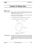
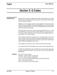
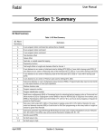
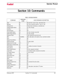
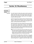
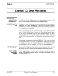
Fadal
User Manual
Section 4: Fixed Cycles
Definition
A Fixed Cycle is a series of operations that directs Z axis and spindle movement
to execute such actions as boring, drilling, and tapping. G codes 73-76 and
81-89 define the operation, while F, I, J, K, P, Q, R0, and Z words (cycle
parameters) define the style of execution.
Procedure to
Initialize a Fixed
Cycle
1) Turn spindle on (M3,M4) at the desired RPM.
2) Position the tool to the I plane (Initial plane), a point above the part and
fixture where the tool will clear all objects.
3) Define the Fixed Cycle with its parameters.
4) Specify a move with X, Y, A, or B locations to execute the cycle.
O1234 (DRILLING EXAMPLE
G0 G90 S10000 M3 E1 X.5 Y-.5 Start the spindle
H1 M8 Z.1 Position to the I plane
G82 G99 R0+.1 Z-.25 F45. P18 Define the cycle and its parameters
X1. Y-.6 Cycle is executed at this next location
I Plane
The I plane (initial plane) is automatically established by the last Z axis position
when the fixed cycle is defined. This is commonly called the maximum Z
clearance position. It is usually established above the highest object on the
part or fixture. It is used with the G98 code to “jump” over obstacles on the part
or fixture. The I plane must always be equal to or above the R plane.
O1234 (DRILLING EXAMPLE
G90 G0 S10000 M3 E1 X.5 Y-.5 Start the spindle H1 M8 Z1.
Z.1 Position to the I plane. The I plane is the last Z position before the cycle
line.
G81 G99 R0+.1 Z-.72 F45. Define the cycle. The R0 plane is equal to the I
plane.
X1. Y-.6 Cycle is executed at this next location
April 2003
Section 4: Fixed Cycles
75
Fadal
User Manual
This represents the location of the R0 plane (or minimum clearance plane). The
R0 plane is where the tool will begin to feed into the material. This location
must be below or equal to the I plane.
R Plane
EXAMPLE:
G90 where the I is equal to the R0 plane
G90 Z.1
G81 R0+.1
EXAMPLE:
G91 where the I is equal to the R plane
G90 Z.1
G91
G81 R0+0
EXAMPLE:
G90 where the R is below the I plane
G90 Z.1
G81 R0-.2
EXAMPLE:
G91 where the R is below the I plane
G90 Z.1
G91
G81 R0-.3
G 98 Return to I
Plane after Final Z
G98 is modal and will remain in effect until the G99 code is used. This code is
also a default code. It is in effect after the HO command is used, or in format 1
when entering the MDI mode or when the auto button is pressed.
When this code is in effect, the tool will return to the I plane after reaching the
final Z axis position. This code is used when the tool must “jump” over any
obstacle. For this reason, it is important to establish the I plane above any
obstacle. When this code appears on a line with a positioning move the tool will
return to the I plane after the cycle has been executed and the tool has reached
the final Z axis position. (See the fixed cycle example in this section.)
G99 Return to R0
Plane after Final Z
Cycle Execution
Format 1
76
This code is modal and will remain in effect until the G98 code is used. When
this code is in effect, the tool will return to the R0 plane after reaching the final
Z axis position.
Fixed Cycles are activated by one of the following which is determined by the
machine parameter settings (see SETP command):
Section 4: Fixed Cycles
April 2003
Fadal
User Manual
1) Immediately execute a cycle when the cycle is defined. (Typical of format 2)
2) Wait for a positional move to execute a cycle. (Typical of format 1)
Note: For Option 2, the positional move can be in the cycle definition line. If
any position words exist in the cycle definition line, the cycle will execute.
The advantage of option two is that a cycle can be initialized from any location,
and then wait for positional moves. The positional moves can all be within a
subroutine or subprogram. The first hole location does not have to be used in
the cycle definition line.
Format 2
Fixed cycles, in format two, will always execute immediately when the cycle is
defined. The first location to execute the cycle must be in the cycle line or
established prior to the cycle line. An L0, used for cycle suspension, can be in
the cycle definition line to suspend execution.
Format 1 & Format 2
If one or more axis moves appear on the same line as the fixed cycle, the cycle
will be executed at the specified position. The cycle will execute at the end of
the move. The move can be a G0, G1, G2, or G3 move. The feed rate
established before the cycle line is the feed rate that will be used for the
positional moves made with G1, G2, or G3. The feed rate on the cycle line will
only affect the Z axis move.
A cycle can remain in effect when moving from one fixture offset to another. If
the position from the first offset to the next offset is the same, an M45 must be
used to execute the cycle. If a cycle is to be executed without a positional
move, use an M45 code to cause execution of the cycle at the current position.
A cycle definition must appear after a G68 line when rotation is being used. The
positioning moves are the only moves that will be affected by the G68 code.
When using a rotary axis the brake may be applied before the execution of the
cycle. Use an M-60 on the same line with the angular position. The machine
will rotate to the angular position, apply the brake, then execute the cycle.
Fixed cycles may only be used in the G17 mode.
Fixed Cycle
Parameters
F Word
Feed rate for drilling and boring.
RPM for tapping (G74, G74.1, G75, G84 and G84.1) Format 1.
April 2003
Section 4: Fixed Cycles
77
Fadal
User Manual
Feed rate for tapping (G74, G74.1, G84 and G84.1) Format 2
Q Word
1) Incremental step distance for intermittent functions (G73, G83). I, J, K
words may be used in place of the Q word.
2) Decimal thread lead for tapping (G74, G74.1, G75, G84, G84.1).
How to compute the Q value for tapping cycles:
Inch mode: Divide 1 by the threads per inch. Example:1/4-20 tap 1/20=.05
Metric mode: Multiply .03937 by the lead. Example: 8mm x 1.25 tap (1.25 is
the lead): .03937 X 1.25= .0492. This will be the inch equivalent for the lead.
3) Y+ axis shift amount before raising the Z axis (G76)
P Word
Dwell time in milliseconds (G76, G82, G88, G89).
1) Parameter used with G73 and G83 which specifies how far to stop above
the bottom of the last peck. When no P word is specified, the tool will
return, in rapid, to the bottom of the last peck.
2) Percentage factor to alter the retracting feed rate on tapping cycles (G74,
G74.1, G75, G84, G84.1). When the value is 10 percent or less, only the
feed rate is modified. Values over 10 percent modify the feed rate and the
spindle speed.
I Word: Initial Peck, X
Axis Shift G76
1) Initial Peck, the value of the first peck (G73, G83).
2) X axis shift amount before raising the Z axis (G76).
J Word: Reducing
Value, Y Axis Shift
G76
1) Reducing Value of each peck until K is reached.
K Word: Minimum
Peck
Minimum Peck Value (G73, G83).
L Word: Cycle Repeat
and Suspend, L# or
L0
2) Y axis shift amount before raising the Z axis (G76).
This represents a cycle repeat or suspend. The cycle will repeat at the line with
this code the number of times indicated. The use of L0 will suppress the cycle
at that line. This can be used to move around an obstacle without executing the
cycle.
G81 G99 R0+.1 Z-.5 F20.
G91 X2. L5 Drill 5 holes 2.0 apart
G90 Y3. L0 Machine moves without drilling
X9. Machine moves and drills at this location
78
Section 4: Fixed Cycles
April 2003
Fadal
User Manual
R Plane: R0 +/- #
This represents the location of the R plane (or minimum clearance plane). The
R plane is where the tool will begin to feed into the material. This location must
be below or equal to the I plane.
In the absolute mode (G90), the value for this location is relative to Z zero. In
the incremental mode (G91), the value for this location is relative to the I plane.
The R0 value in the incremental mode can never be a positive value.
S Word
Spindle Speed for tapping (G74, G74.1, G84 and G84.1) Format 2.
Z Word
The Z word establishes two separate locations. The first is the Initial Plane. This
is the location of the Z axis when the fixed cycle is defined. This should be the
minimum clearance above all clamps and fixtures. When a G98 is coded the Z
axis returns to the Z axis location after completion of the final Z depth. The
second use for Z is the final Z depth of the cycle. In absolute mode (G90), it is
the depth relative to zero. In incremental mode (G91), it is the depth below the
R0 plane. The use of the Z word while a cycle is active will redefine the cycle's
final Z depth until the cycle is canceled or changed. It does not redefine the
Initial Plane. When it is desired to change the return point of the Z axis, the R0
must be redefined with the new final Z depth (see example).
Fixed Cycle
Examples
N1 O1234 (FIXED CYCLE EXAMPLE
N2 M6 T1 (TOOL #1
N3 G0 G90 S8000 M3 E1 X0 Y0 Start the spindle and move to fixture one
N4 H1 M8 Z.1 Move the tool to the initial plane .1 above the part.
N5 G73 G99 R0-.45 Z-1.2 F10. Q.26 X-.5 Y-.35 P.02 Define cycle and execute
at hole #1.
N6 Y-.7 Execute cycle at hole #2 and remain at the R plane.
N7 Y-1.05 G98 Execute cycle at hole #3 and then return to the I plane.
N8 X-2.5 G99 Execute cycle at hole #4 and remain at the R plane.
N9 Y-.7 Execute cycle at hole #5 and remain at the R plane.
N10 Y-.35 Execute cycle at hole #6 and remain at the R plane.
N11 G80 Cancel the fixed cycle and return to the I plane.
The Z axis zero position for this example is established at the top of the part.
The I plane is Z+.1 above the part. The R plane is established Z -.45 from the
top of the part.
April 2003
Section 4: Fixed Cycles
79
Fadal
User Manual
2.50
.50
.35
1.05
.70
R PLANE
INITIAL PLANE
.10
1.0
.45
.50
1.2
FINAL DEPTH Z
Figure 4-1 Fixed Cycle Examples
EXAMPLE:
The following example performs the same functions as before with various Z
depth changes.
G90 Z.1
G81 G98 R0+.1 Z-.5 F40 X1.0 Y1.0
X2.0 Z-.7 R0+.1
X
X3.0 Z-.3 R0+.1
Y-1.0
Y-2.0 Z-.8 R0+.1
Note: Restate R0 even if not changed.
80
Section 4: Fixed Cycles
April 2003
Fadal
G73 Peck Drilling
Using Q
User Manual
N3 G73 G99 R0+.1 Z-1.2 F10. Q.1 P.02 X-.50 Y-.35
Drill .25 each step (Q.26), returning incrementally +.05 after each peck, then
down -.03 (.05 -.02 due to P.02) to the next peck plane, until the final depth is
accomplished. The Q word can be calculated by dividing the distance from the
R plane to the final Z by the number of desired steps. Example: 1.2+.1=1.3 for
total distance then 1.3 (distance) / 10 (steps)=.1 for the Q value.
G73 Peck Drilling
Using I, J, K
N3 G73 G99 R0+.1 Z-1.2 F10. I.4 J.09 K.01 P.02 X-.50 Y-.35
Drill using varying step sizes, returning incrementally +.05 after each peck,
then down -.03 (.05 -.02 due to P.02) to the next peck plane, until the final
depth is accomplished. (See Deep Hole Drilling in this section for details.)
G74 Left Hand
Tapping
N3 G74 G99 R0+.4 Z-1.2 F550.2 Q.05 X-.50 Y-.35
Tap at 550 RPM in the high range, with a thread lead of .05 (20 threads per
inch) to the final Z depth, then the spindle stops and reverses, retracting the Z
axis. (See Tapping cycles in this section for details.)
G74.1 Left Hand
Rigid Tapping
N3 G74.1 G99 R0+.4 Z-1.2 F2000. Q.05 X-.50 Y-.35
Tap at 2000 RPM in the high range at a feed rate calculated by the CNC, the
spindle stops and reverses, retracting the Z axis to the R plane. (See Tapping
Cycles in this section for details.)
G75 Tapping Head
Cycle
N3 G75 G99 R0+.4 Z-1.2 F2000. Q.050 X-.50 Y-.350
Tap at 2000 RPM in the low range, with thread lead of .050 (20 threads per
inch) to the final Z depth, then feed up to the R plane,. (See Tapping cycles in
this section for details.)
G76 Fine Boring
N3 G76 G99 R0+.1 Z-1.2 F10. Q.01 X-.50 Y-.35
Bore Z-.55, spindle stop-orient (the orientation will be the opposite of the
starting spindle direction), shift the Y axis +.01, retract the Z axis, then move
the Y axis -.01.
G81 Spot Drilling
April 2003
N3 G81 G99 R0+.1 Z-1.2 F10. X-.50 Y-.35
Section 4: Fixed Cycles
81
Fadal
User Manual
Drill in one complete motion at a feed rate of 10.0 IPM.
G82 Counter Boring,
Center Drilling, Spot
Facing
N3 G82 G99 R0+.1 Z-1.2 F10. P23 X-.50 Y-.35
Bore to depth, dwell for 23 milliseconds then retract the Z axis at high speed.
Dwell time for three revolutions: 180000/RPM = P word value.
G83 Deep Hole
Drilling Using Q
N3 G83 G99 R0+.1 Z-1.2 F10. Q.1 P.02 X-.50 Y-.35
Drill .1 each step, returning in rapid after each step to the R plane, then down in
rapid to .02 (P.02) above the last step until the final Z depth is accomplished.
The Q word can be calculated by dividing the distance from the R plane to the
final Z by the number of desired steps. Example: 1.2+.1=1.3 for total distance
then 1.3 (distance) / 13 (steps)=.1 for the Q value.
G83 Deep Hole
Drilling Using I, J, K
N3 G83 G99 R0+.1 Z-1.2 F10. I.4 J.09 K.01 X-.50 Y-.35
Drill using varying step sizes, returning after each increment to the R plane then
down until final depth is accomplished. (See Deep Hole Programming Using
G73 and G83 I, J, and K in this section for details.)
G84 Right Hand
Tapping
G84 Right Hand
Tapping Using P
Word
82
N3 G84 G99 R0+.1 Z-1.2 F550.2 Q.05 X-.50 Y-.35 (Format 1)
Tap at 750 RPM in the high range, with a thread lead of .05 (20 threads per
inch) to final Z depth, then the spindle stops and reverses, retracting the Z axis.
(See Tapping Cycles in this section for details.)
N3 G84 G99 R0+.1 Z-1.2 F550.2 Q.05 P2 X-.50 Y-.35
Tap at 750 RPM in the high range at a feed rate calculated by the CNC, the
spindle stops and reverses, retracting the Z axis to the R plane at a rate faster
than the in feed rate by 2%, as stated by the “P” word. (See Tapping Cycles in
this section for details.)
Section 4: Fixed Cycles
April 2003
Fadal
User Manual
G84.1 Right Hand
Rigid Tapping
N3 G84.1 G99 R0+.1Z-1.2 F2000.2 Q.05 X-.50 Y-.35 (Format 1)
Tap at 2000 RPM in the high range at a feed rate calculated by the CNC, the
spindle stops and reverses, retracting the Z axis to the R plane. (See Tapping
cycles in this section for details.)
G85 Bore In, Bore
Out
N3 G85 G99 R0+.1 Z-1.2 F10. X-.50 Y-.35
G86 Bore In, Spindle
Off, Orient, Rapid
Out
N3 G86 G99 R0+.1 Z-1.2 F10. X-.50 Y-.35
G87 Bore In, Bore
Out
N3 G87 G99 R0+.1 Z-1.2 F10. X-.50 Y-.35
G88 Bore In, Dwell,
Bore Out
N3 G88 G99 R0+.1 Z-1.2 F10. P23 X-.50 Y-.35
Bore in at a feed rate of 10 IPM. Dwell for 23 milliseconds, then bore out. Dwell
time for three revolutions: 180000/RPM = P word value
G89 Bore In, Dwell,
Bore Out
N3 G89 G99 R0+.1 Z-1.2 F10. P23 X-.50 Y-.35
Bore in at a feed rate of 10 IPM. Dwell for 23 milliseconds, then bore out. Dwell
time for three revolutions: 180000/RPM = P word value.
Table 1: Cycle Summary
Code
Movement In
Dwell at
Bottom
Spindle at
Bottom
Movement Out
G73
Steps
-
-
Rapid
Peck Drilling
G74
Feed
-
Reverses
Feed
LH Tap Compression Holder
G74.1
Feed
-
Reverses
Feed
Left Hand Rigid Tapping
G75
Feed
-
No Reverse
Feed
Self Reversing Tapping Head
G76
Feed
Yes
Orient, Axis
Shift
Rapid
Fine Boring
G81
Feed
-
-
Rapid
Drill
G82
Feed
Yes
-
Rapid
Center Drill, Counter Bore
G83
Intermittent
-
-
Rapid
Deep Hole
G84
Feed
-
Reverses
Feed
RH Tap Compression Holder
G84.1
Feed
-
Reverses
Feed
Right Hand Rigid Tapping
G85
Feed
-
-
Feed
Boring
G86
Feed
-
Orient
Rapid
Boring
April 2003
Section 4: Fixed Cycles
Typical Usage
83
Fadal
User Manual
Table 1: Cycle Summary
Code
Movement In
Dwell at
Bottom
Spindle at
Bottom
Movement Out
G87
Feed
-
-
Feed
Boring
G88
Feed
Yes
-
Feed
Boring
G89
Feed
Yes
-
Feed
Boring
Typical Usage
G80 - Cancel Cycles
G98 - Return to initial plane after final Z
G99 - Return to R0 plane after final Z
G73 - Peck Drilling
using Q
G73 G99(G98) RO...Z...F...Q...P...(OPTIONAL)
I PLANE
(G98)
X,Y
R PLANE
(G99)
Q
P
Q
P
.
Q
Z FINAL
DEPTH
Q=PECK SIZE
P=FEED DISTANCE
(BEFORE PECK)
RAPID MOVES
FEED RATES
Figure 4-2 Peck Drilling Using Q
84
Section 4: Fixed Cycles
April 2003
Fadal
User Manual
G73 - Peck Drilling
using I, J, K
G73 G99(G98) R0...Z...F...I...J...K...P...(OPTIONAL)
I PLANE
(G98)
X,Y
R PLANE
(G99)
I
P
.
P
.
P
K
K
.
Z FINAL
DEPTH
PREVIOUS
PECK MINUS J
I=INITIAL PECK
J=REDUCING VALUE
K=MINIMUM PECK
P=FEED DISTANCE
(BEFORE PECK)
RAPID MOVES
FEED RATES
Figure 4-3 Peck Drilling Using I, J, K
April 2003
Section 4: Fixed Cycles
85
Fadal
User Manual
G74 - Left Hand
Tapping (Format 1)
FORMAT 1
G74 G99(G98) RO...Z...F...Q...P..
...(OPTIONAL)
I PLANE
(G98)
X,Y
SPINDLE
REVERSE
R PLANE
(G99)
Z FINAL
DEPTH
.
SPINDLE FORWARD
F=RPM
Q=THREAD LEAD
P=RETRACT FEED %
(OPTIONAL)
RAPID MOVES
FEED RATES
Figure 4-4 Left Hand Tapping (1)
86
Section 4: Fixed Cycles
April 2003
Fadal
User Manual
G74 - Left Hand
Tapping (Format 2)
FORMAT 2
G74 G99(G98) RO...Z...F...P..
...(OPTIONAL)
I PLANE
(G98)
X,Y
SPINDLE
REVERSE
R PLANE
(G99)
.
Z FINAL
DEPTH
SPINDLE FORWARD
F=RPM
P=RETRACT FEED %
(OPTIONAL)
RAPID MOVES
FEED RATES
Figure 4-5 Left Hand Tapping (2)
April 2003
Section 4: Fixed Cycles
87
Fadal
G75 - Tapping Head
Cycle
(Formats 1 & 2)
User Manual
FORMAT 1 & 2
G75 G99(G98) RO...Z...F...Q...P..
...(OPTIONAL)
I PLANE
(G98)
X,Y
SPINDLE
REVERSE
R PLANE
(G99)
.
Z FINAL
DEPTH
F=RPM
Q=THREAD LEAD
P=RETRACT FEED %
(OPTIONAL)
RAPID MOVES
FEED RATES
Figure 4-6 Tapping Head Cycle (1&2)
G76 - Fine Boring
Using Q
G76 G99(G98) RO...Z...F...Q.
X,Y
I PLANE
(G98)
R PLANE
(G99)
.
X+
SHIFT
Z FINAL
DEPTH
SPINDLE STOP
AND ORIENT
Q=AMOUNT OF Y+ SHIFT
RAPID MOVES
FEED RATES
Figure 4-7 Fine Boring Using Q
88
Section 4: Fixed Cycles
April 2003
Fadal
G76 - Fine Boring
Using I, J
User Manual
G76 G99(G98) RO...Z...F...I...J...
I PLANE
(G98)
X,Y
R PLANE
(G99)
.
X&Y
SHIFT
Z FINAL
DEPTH
SPINDLE STOP
AND ORIENT
I=AMOUNT & DIRECTION OF X SHIFT
J=AMOUNT & DIRECTION OF Y SHIFT
RAPID MOVES
FEED RATES
Figure 4-8 Fine Boring Using I, J
G81 - Spot Drilling
Note: Use G82 for center drilling.
G81 G99(G98) RO...Z...F...
I PLANE
(G98)
X,Y
R PLANE
(G99)
.
Z FINAL
DEPTH
RAPID MOVES
FEED RATES
Figure 4-9 Spot Drilling
April 2003
Section 4: Fixed Cycles
89
Fadal
G82 - Counter
Boring
User Manual
Use this for center drilling, counter sinking, and counter boring.
Dwell time for three revolutions is calculated: 180000/RPM=P word value
G82 G99(G98) RO...Z...F...P...
I PLANE
(G98)
X,Y
R PLANE
(G99)
DWELL
.
Z FINAL
DEPTH
P=AMOUNT OF DWELL
(IN MILLISECONDS)
RAPID MOVES
FEED RATES
Figure 4-10 Counter Boring
G83 - Deep Hole
Drilling Using Q
G83 G99(G98) RO...Z...F...Q...
P...(OPTIONAL)
X,Y
I PLANE
(G98)
R PLANE
(G99)
Q
Q
Z FINAL
DEPTH
L=PECK SIZE
P=FEED DISTANCE BEFORE
PECK (OPTIONAL)
RAPID MOVES
FEED RATES
Figure 4-11 Deep Hole Drilling Using Q
90
Section 4: Fixed Cycles
April 2003
Fadal
User Manual
G83 - Deep Hole
Drilling using I, J, K
G83 G99(G98) R0...Z...F...I...J...K...P...(OPTIONAL)
I PLANE
(G98)
X,Y
R PLANE
(G99)
I
P
.
P
.
P
K
K
.
Z FINAL
DEPTH
PREVIOUS
PECK MINUS J
I=INITIAL PECK
J=REDUCING VALUE
K=MINIMUM PECK
P=FEED DISTANCE
BEFORE PECK
RAPID MOVES
FEED RATES
Figure 4-12 Deep Hole Drilling Using I, J, K
April 2003
Section 4: Fixed Cycles
91
Fadal
User Manual
G84 - Right Hand
Tapping (Format 1)
FORMAT 1
G84 G99(G98) RO...Z...F...Q...P..
...(OPTIONAL)
I PLANE
(G98)
X,Y
SPINDLE
FORWARD
R PLANE
(G99)
Z FINAL
DEPTH
.
SPINDLE REVERSE
F=RPM
Q=THREAD LEAD
P=RETRACT FEED %
(OPTIONAL)
RAPID MOVES
FEED RATES
Figure 4-13 Right Hand Tapping (1)
92
Section 4: Fixed Cycles
April 2003
Fadal
User Manual
G84 - Right Hand
Tapping (Format 2)
FORMAT 2
G84 G99(G98) RO...Z...F...P..
...(OPTIONAL)
I PLANE
(G98)
X,Y
SPINDLE
FORWARD
R PLANE
(G99)
Z FINAL
DEPTH
.
SPINDLE REVERSE
F=RPM
P=RETRACT FEED %
(OPTIONAL)
RAPID MOVES
FEED RATES
Figure 4-14 Right Hand Tapping (2)
G85 - Bore In, Bore
Out
G85 G99(G98) RO...Z...F
I PLANE
(G98)
X,Y
R PLANE
(G99)
.
Z FINAL
DEPTH
RAPID MOVES
FEED RATES
Figure 4-15 G85-Bore In, Bore Out
April 2003
Section 4: Fixed Cycles
93
Fadal
User Manual
G86 - Bore In,
Spindle Off, Rapid
Out
G86 G99(G98) RO...Z...F
I PLANE
(G98)
X,Y
R PLANE
(G99)
Z FINAL
DEPTH
.
SPINDLE STOP
AND ORIENT
RAPID MOVES
FEED RATES
Figure 4-16 G86-Bore In, Spindle Off, Rapid Out
G87 - Bore In, Bore
Out
G87 G99(G98) RO...Z...F
I PLANE
(G98)
X,Y
R PLANE
(G99)
Z FINAL
DEPTH
.
RAPID MOVES
FEED RATES
Figure 4-17 G87-Bore In, Bore Out
94
Section 4: Fixed Cycles
April 2003
Fadal
G88 - Bore In, Dwell,
Bore Out
User Manual
Dwell time for three revolutions is calculated: 180000/RPM=P word value
G88 G99(G98) RO...Z...F
X,Y
I PLANE
(G98)
R PLANE
(G99)
Z FINAL
DEPTH
.
DWELL
P=DWELL IN MILLISECONDS
RAPID MOVES
FEED RATES
Figure 4-18 G88-Bore In, Dwell, Bore Out
G89 - Bore In, Dwell,
Bore Out
Dwell time for three revolutions is calculated: 180000/RPM=P word value
G89 G99(G98) RO...Z...F
X,Y
I PLANE
(G98)
R PLANE
(G99)
.
Z FINAL
DEPTH
DWELL
P=DWELL IN MILLISECONDS
RAPID MOVES
FEED RATES
Figure 4-19 G88-Bore In, Dwell, Bore Out
April 2003
Section 4: Fixed Cycles
95
Fadal
User Manual
Tapping Cycles
General Tapping
Rules
The fixed cycle used for tapping is depends on which tapping attachment is
being used. The cycles and examples given here have been approved by the
tapping attachment manufacture specified.
Ramping:
Program a G8 (No Ramps) for the tap operation. This allows the tool to feed at
a constant rate in and out of the hole.
Clearance:
The rapid plane (R0 Plane) should be at least .4 above the hole to be tapped.
This insures that the tap fully retracts prior to movement to the next position.
Spindle Speed:
When using the G74 and G84 cycles, the spindle should be programmed for
the high gear range. This will provide better spindle reversal for tapping. This is
accomplished by programming a “.2" at the end of the S word or F word. For
example, S1000.2 or F1000.2 sets the spindle speed at 1000 rpm in the high
gear range.
Feed Rate:
The feed rate is determined by the thread lead and spindle RPM. The thread
lead is calculated as 1 divided by the number of threads per inch. When using
G74 and G84, the feed rates may be programmed differently for Format 1 and
Format 2. When using the G85 cycle for tapping, the feed rate must be
calculated by the programmer for Format 1 or Format 2. When using rigid
tapping in Format 2 and the F word requires decimal entries, use at least three
place accuracy.
96
Format 1
The feed rate is calculated by the control. These cycles are programmed using
the F word for RPM and the Q word for thread lead. G74, G75 and G84
calculate the feed rate as the RPM times the thread lead. These cycles
automatically use 100 percent of this calculation for the feed rate into the hole
and 105 percent for the feed rate out of the hole. The P word may be used to
increase or decrease the feed rate out of the hole. Use a positive P to increase
and a negative P to decrease the feed rate out of the hole.
Format 2
The feed rate must be calculated by the programmer. These cycles use the F
word as feed rate and do not use the Q word. The F word in the cycle indicates
the calculated feed rate.
Section 4: Fixed Cycles
April 2003
Fadal
User Manual
Feed Rate
Calculation
EXAMPLE:
The feed rate programmed should use 100 percent of the optimum feed rate.
The optimum feed rate is the RPM times the thread lead.
1/4-20 Tap at 2000 RPM
Feed rate = (1 / threads per inch) * RPM
= (1 / 20) * 2000
= .05 * 2000
= 100.
Blind Holes:
The procedure described is ONLY a guideline for blind hole tapping. Begin
tapping to a depth 2/3 of the desired final Z depth. Gradually increase the
programmed depth until the final Z depth is reached. This method reduces the
possibility of feeding the tool into the material at the bottom of the hole.
Tap Sizes:
Tapping attachments vary with the desired size of the tap. Insure the proper
attachment is used for the tap size. The chart below lists the recommended
minimum and maximum size tap for each attachment.
Table 2: TAPMATIC
SERIES
MAX RPM
TAP CAPACITY
MAX CUTTING
MAX FORMING
NCR-00
5000
#00 - #4
#4
#3
NCR-0A
3000
#4 - 1/4
1/4
1/4
NCR-1A
2000
#10 - 1/2
1/2
1/2
NCR-2A
1000
3/8 - 3/4
3/4
9/16
SPD-3
2000
#0 - 1/4
1/4
1/4
SPD-5
1500
#6 - 1/2
1/2
1/2
SPD-7
1200
#10 - 3/4
3/4
9/16
Table 3: PROCUNIER
SERIES
MAX RPM
TAP CAPACITY
MAX CUTTING
MAX FORMING
15001
3000
#0 - 1/4
1/4
#10
Note: The maximum cutting and forming tap sizes for the Tapmatic are based
on free machining steel. When tapping aluminum, the tap size should not
exceed the tapping attachment maximum size.
April 2003
Section 4: Fixed Cycles
97
Fadal
User Manual
Program Coding:
Program coding varies with the tapping attachment and the machine format.
Below are examples of the most common uses and attachments.
Metric Threads:
Metric threads may be cut in the inches mode. The Q word is calculated using
the thread pitch of the tap. The thread pitch is multiplied by .03937 to convert
to inches for the control. For an m8 x 1.25 thread, the Q word is calculated as
follows:
EXAMPLE:
Program Examples
EXAMPLE:
Rigid Tapping
9
OPTIONAL
FEATURE
Format 1
Q = 1.25 * .03937
Q = .0492
H1 Z1.0 M8
G84 G98 R0+.4 Z-1.025 F500.2 Q.0492 X.5 Y-.5
The following examples describe the program for a 1/4-20 thread, .3 deep, at
2000 rpm.
Format 1
N52 G0 G90 S2000 M3 E1 X0 Y0
N53 H1 M7 Z.4
N54 G84 G99 R0+.4 Z-.3 F2000 Q.05 X0 Y0
N55 X.5
N56 X1.
N57 G80
Rigid tapping may be accomplished for right or left hand threads. The rigid
tapping cycles are programmed in the same manner as the compression tap
holders. The taps may be held in a collet or solid tool holder.
Note: Rigid tapping requires a special drive for operation. The machine must
also have a C axis controller for the spindle. In the back panel of the VMC,
the spindle driver should be labeled with Horsepower and Rigid Tap. If the
VMC only has a Horsepower label, it does not have Rigid Tap. Please refer
to the VMC Maintenance Manual for further information.
Note: 10,000 rpm spindle 3,000 rpm max, 7,500 rpm spindle 1,500 rpm
max, 15,000 rpm spindle 3,000 rpm max.
The program codes for rigid tapping are G74.1, G74.2, G84.1, and G84.2. The
G74.1 and G84.1 are coded the same as G74 and G84. Prior to beginning the
98
Section 4: Fixed Cycles
April 2003
Fadal
User Manual
tapping cycle, the machine prepares the spindle. This is an automatic process
accomplished by four revolutions of the spindle. The preparation is done after
the H offset is applied and just before the cycle begins. The use of the G74.2 or
G84.2 prepares the cycle for execution during the H offset application.
The machine uses the low range for tapping at 750 rpm and below. When the
rpm is above 751 the machine uses the high range. When using the G84.2 or
G74.2, and the programmed rpm is above 750, the S#.2 should be used on the
initial spindle speed call. This sets the proper belt range for the cycle
preparation. The G84.1 and G74.1 automatically set the proper range for
preparation. The G74.1 and G84.1 automatically release the spindle
orientation lock. The rpm specified, before and after the H word must be the
same.
The Gain parameter setting (in SETP) is used to adjust the spindle speed and
feed rate correlation. The gain may be set from 0 to 255. Please contact your
dealer or refer to the VMC maintenance manual for further information.
The Ramp parameter setting (in SETP) is used to adjust the acceleration time
of the spindle. The ramp may be set from 0 to 100. The higher the ramp
number, the longer the time for acceleration.
EXAMPLE:
N52 G0 G90 S.2 M5 G80 M90 Do not turn the spindle on!
N53 G84.2
N54 H1 M7 Z.4
N55 G84.1 G99 R0+.4 Z-.3 F2000.2 Q.05 X0 Y0
N56 X1.
N57 G80
EXAMPLE:
N52 G0 G90 S2000.2 M5 G80 M90 Do not turn the spindle on!
N53 G84.2
N54 H1 M7 Z.4
N55 G84.1 G99 R0+.4 Z-.3 S2000.2 F100. X0 Y0
100% feed calculation here
N56 X1.
N57 G80
Tapmatic NCR Series
April 2003
The tapping heads in this series should use the G85 Bore Cycle. The feed rate
and spindle potentiometers should be disabled. The following formula
calculates the required feed rate.
Section 4: Fixed Cycles
99
Fadal
User Manual
M48, M49:
When using the Bore Cycle (G85), the feed rate and spindle speed
potentiometers must be disabled. With the potentiometers disabled the
machine uses the programmed feed rates. This is accomplished with the M49
code. At the completion of the cycle the potentiometers should be enabled with
the M48 code.
Feedrate = ((1 / threads per inch) * RPM) * 95%
= ((1 / 20) * 2000) * .95
= (.05 * 2000) * .95
= 100. * .95
= 95.
EXAMPLE:
(Format 1 or Format 2):
N1 O1 (TAPMATIC NCR SERIES
N2 G0 G8 G90 S2000 M3 E1 X0 Y0
N3 H1 M7 Z.4
N4 M49
N5 G85 G99 R0+.4 Z-.3 F95. X0 Y0
N6 X1.
N7 G80 M48
N8 M5 M9
Tapmatic SPD Series
EXAMPLE:
The tapping heads in this series should use the G75 Tapping Cycle.
(Format 1 or Format 2):
N1 O1 (TAPMATIC SPD SERIES
N2 G0 G8 G90 S2000 M3 E1 X0 Y0
N3 H1 M7 Z.4
N4 G75 G99 R0+.4 Z-.3 F2000. Q.05 X0 Y0
N5 X1.
N6 G80
N7 M5 M9
100
Section 4: Fixed Cycles
April 2003
Fadal
User Manual
Procunier Series
EXAMPLE:
The tapping heads in this series should use the G75 Tapping Cycle.
(Format 1 or Format 2):
N1 O1 (PROCUNIER SERIES
N2 G0 G8 G90 S2000 M3 E1 X0 Y0
N3 H1 M7 Z.4
N4 G75 G99 R0+.4 Z-.3 F2000. Q.05 X0 Y0
N5 X1.
N6 G80
N7 M5 M9
Compression (non
self-reversing) Tap
Holder Series
EXAMPLE:
These tapping heads should use the G84 or G74 Tapping cycle. It is best to use
these in the high range (S word with a .2). The P word may be used to increase
the feed rate of the tap when it reverses, if the F word is used for the RPM and
the Q word is used for the lead. The G74 is used in Format 1 style ONLY.
Format 1:
N1 O1 (COMPRESSION TAP HOLDER SERIES
N2 G0 G8 G90 S1000.2 M3 E1 X0 Y0
N3 H1 M7 Z.4
N4 G84 G99 R0+.4 Z-.3 F1000. Q.05 X0 Y0
N5 X1.
N6 G80
N7 M5 M9
EXAMPLE:
Format 2:
The following formula calculates the required feed rate:
Feed rate = ((1 / threads per inch) * RPM)
= ((1 / 20) * 1000)
= (.05 * 1000)
= 50.
N1 O1 (COMPRESSION TAP HOLDER SERIES
N2 G0 G8 G90 S1000.2 M3 E1 X0 Y0
N3 H1 M7 Z.4
N4 G84 G99 R0+.4 Z-.3 S1000.2 F50. X0 Y0 100% feed calculation here
N5 X1.
N6 G80
N7 M5 M9
April 2003
Section 4: Fixed Cycles
101
Fadal
User Manual
Deep Hole
Programming Using
G73 and G83 I, J,
and K
The G73 and G83 I, J, K programming options allow the programmer to
customize the drill cycle steps up to the final Z depth. This would be used when
the steps can be large at the top of the hole and need to be reduced as the tool
feeds deeper into the part.
Initial Peck: I#
The I word represents the depth of the first peck starting from the R plane
(minimum clearance plane). The rule of thumb for this value is 2 to 3 times the
diameter of the drill but may be larger or smaller as required. This value is
always an incremental value.
Reducing Factor: J#
The J word represents a reducing value. The J value will be subtracted from the
I value for the second peck and from each subsequent peck. Each peck will be
smaller than the last peck by the amount of the J value until the peck size is
equal to the K value. This value is always an incremental value.
Minimum Peck: K#
The K word represents the minimum peck value. The I value will be reduced by
the J value until the K value is reached. The remainder of the hole will be drilled
in a series of pecks each equal to the K value.
Feed Distance
Before Next Peck: P#
The P word represents the distance to feed before the next peck. Without the P,
the tool will rapid all the way to the next peck. The P will specify how far above
he next peck to begin feeding into the material. This parameter is especially
helpful if chips fall into the hole during a retraction move. The tool will not crash
into the chips if the P value is large enough.
Peck Drill: G73
The G73 peck drilling cycle is a chip breaker cycle that does not retract all of the
way out of the hole. The retract distance is set by the CNC and cannot be
changed by the programmer. It is an excellent cycle for free machining
materials and drill geometries that allow for efficient chip removal. In these
cases there is a time savings in the cycle because the drill does not retract out
of the hole.
Deep Hole Drill: G83
The G83 Peck Drilling Cycle retracts to the R plane (minimum clearance plane)
on the completion of each peck. It is an excellent cycle to break and clear chips
and for drill geometries that are prone to packing chips.
EXAMPLE:
This example is for a 1/4 dia drill drilling 1 1/4 inches deep.
EXAMPLE:
G73:
G73 X0 Y0 Z-1.25 R+.1 I.5 J.2 K.1 F10. G98 (G99)
102
Section 4: Fixed Cycles
April 2003