1
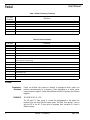
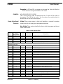
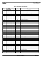
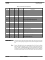
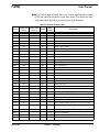
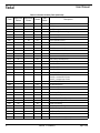
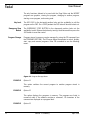
Fadal
User Manual
Section 1: Summary
NC Word Summary
Table 1: NC Word Summary
NC Word
Summary
Definition
A
A axis angular motion command (or optional Servo Coolant)
B
B axis angular motion command
C
C axis angular motion command
D
Tool diameter offset
E
Fixture offset
F
Feed rate, or spindle speed for tapping
G
Preparatory function
H
Tool length offset or Length and diameter offset for Format 1
I
X axis distance to arc center or Initial peck size for drilling (G73 G83) or X axis shift in boring cycle (G76) JY
axis distance to arc center or Reducing value of the initial peck (G73, G83) or Y axis shift in boring cycle (G76)
J
Y axis distance to arc center or Reducing value of the initial peck (G73, G83) or Y axis shift in boring cycle
(G76)
K
Z axis distance to arc center or Minimum peck size for drilling (G73, G83)
L
Subroutine definition or call or Subprogram repeat function (M98) or Programmable data input function (G10)
or Line repeat function or Fixed cycle repetitions
M
Machine function code
N
Program sequence number
O
Program identification number
P
Dwell time in milliseconds (G04) or Percentage factor for retracting feed on tapping cycles or Fixture and tool
offset number (G10) or Subprogram number (M98) or Value for R0-R9 (G10) or Sequence/ line number jump
(M99) or Feed distance before peck (G73 G83) or P1 with G17 Q to use B axis during mapping or Angular tolerance for Feed Forward
Q
Peck size in drill cycles (G73, G83) or Thread lead in tapping cycles (G74, G75, G84) or Diameter for automatic tool diameter override (H99) or Scale factor for Flat Cam programming on the rotary table or Length tolerance to ignore Feed Forward
R
Subroutine parameter input R0 through R9 R0 Plane for fixed cycle or Radius designation (circular interpolation, G2 & G3) or Tool offset value amount (G10) Parametric Variables R0, R1 - R9
S
Spindle speed (RPM)
S.1
Set belt range to low
S.2
April 2003
Set belt range to high
Section 1: Summary
1
Fadal
User Manual
Table 1: NC Word Summary (Continued)
NC Word
Summary
Definition
T
Tool number selector for turret
V
Variables in Macros (V1-V100)
X
X axis motion command
Y
Y axis motion command
Z
Z axis motion command
Table 2: Character Summary
Character
Definition
0-9
Numerical digits
A-Z
Alphabetical characters
%
Program start or end, rewind to start
+
Plus, positive
-
Minus, negative
(
Comment start (standard NC program), or Engraving text start (L9201 Fixed Subroutine), or Mathematical
operator (Macro Programming)
.
Decimal point
,
Comma
EOB
ENTER key, carriage return / line feed (ASCII 13,10)
*
Comment start
/
Optional block skip
:
Program identification number (Format 2)
#
Macro Line Identification
G Codes
2
Preparatory
Functions
Codes are divided into groups or families to distinguish which codes can
function simultaneously in a program. Codes belonging to a similar group
cannot function together. Codes from different families or groups can function
together.
EXAMPLE:
N11 G90 G0 G1 X1. F40.
The G0 and G1, from group A, cannot be programmed in the same line
because they are both from the same group. The G90, from group F, can be
with the G0 or the G1, if they were on separate lines, because it is from a
different group.
Section 1: Summary
April 2003
Fadal
User Manual
Exception: A G90 and G91 can appear on the same line. Each will affect the
motion words to the right of the G90 or G91 codes.
EXAMPLE:
N14 G90 X5.321 G91 Y.25 G90
The X move will be made in absolute and the Y move will be made in
incremental. The G90 at the end of the line places the machine back in
absolute for the next line of the program.
Modal & Non Modal
Functions
Modal: These codes remain in effect until modified or canceled by another
modal code with the same group designation code letter.
Non Modal: These codes only affect the line in which they appear and do not
cancel modal codes.
Table 3: G Code Summary Table
Code
Group
Designation
Modal
Non Modal
G0
A
Yes
-
G1
A
Yes
* see note
Linear Interpolation
G2
A
Yes
* see note
Circular Interpolation Clockwise
G3
A
Yes
* see note
Circular Interpolation Counterclockwise
Description
Rapid Travel (Point-to-Point Positioning)
Note: G2 and G3 cancel G0 and remain active until canceled by each other. With G2 or G3 active, a move without I, J, K, or R
is considered linear (G1).
G4
B
-
Yes
Dwell
G5
A
-
Yes
Non Modal Rapid Travel
G8
D
Yes
-
Acceleration (No Feed Ramps)
G9
D
Yes
-
Deceleration (Feed Ramps & In-Position Check)
G10
I
-
Yes
G15
C
Yes
-
YZ Circular plane with simultaneous A axis
G17
C
Yes
-
XY plane selection
G17.1
C*
Yes
-
AB word swap
G17.2
C
Yes
-
AB word swap cancel
G18
C
Yes
-
XZ plane selection
G19
C
Yes
-
YZ plane selection
G20
M
-
Yes
Check parameters for inches mode set in SETP
G21
M
-
Yes
Check parameters for metric mode set in SETP
G28
I
-
Yes
Return to current zero (set home) position
G28.1
I
-
Yes
Return from Jog Away
G29
I
-
Yes
Return from current zero (set home) position
G31
I
-
Yes
Probe touch function (Skip Function)
G31.1
I
-
Yes
Probe no touch function
April 2003
Programmable Data Input
Section 1: Summary
3
Fadal
User Manual
Table 3: G Code Summary Table (Continued)
4
Code
Group
Designation
Modal
Non Modal
G40
D
Yes
-
Cutter compensation canceled
G41
D
Yes
-
Cutter compensation left (climb)
G42
D
Yes
-
Cutter compensation right (conventional)
G43
J
Yes
-
Tool length compensation positive
G44
J
Yes
-
Tool length compensation negative
G45
I
-
Yes
Tool offset single expansion
G46
I
-
Yes
Tool offset single reduction
G47
I
-
Yes
Tool offset double expansion
G48
I
-
Yes
Tool offset double reduction
G49
J
Yes
-
Tool length offset cancel
G50
J
Yes
-
Ramp slope control cancel
G50.1
J
Yes
-
Mirror image cancel
G51
J
Description
Yes
-
Ramp slope control
G51.1
J
*
Yes
-
Mirror image
G51.2
J*
Yes
-
Tool Load Compensation
G51.3
J*
Yes
-
Axis Scaling
G52
I
Yes
-
Coordinate system shift
G53
I
-
Yes
G54
O
Yes
-
Fixture offset 1 (E1)
G55
O
Yes
-
Fixture offset 2 (E2)
G56
O
Yes
-
Fixture offset 3 (E3)
G57
O
Yes
-
Fixture offset 4 (E4)
G58
O
Yes
-
Fixture offset 5 (E5)
G59
O
Yes
-
Fixture offset 6 (E6)
G66
C
Yes
-
Modal subroutine
G67
C
Yes
-
Modal subroutine cancel
G68
C
Yes
-
Rotation
G69
C
Yes
-
Rotation cancel
G70
M
Yes
-
Check parameters for inches mode set in SETP
G71
M
Yes
-
Check parameters for metric mode set in SETP
G73
E
Yes
-
Peck drill cycle
G74
E
Yes
-
Left hand tapping with compression holder
G74.1
E
Yes
-
Left hand Rigid tapping
G74.2
E
Yes
-
Prepare for Left hand Rigid tapping (optional)
G75
E
Yes
-
Tapping cycle with self-reversing head
Machine coordinate system
Section 1: Summary
April 2003
Fadal
User Manual
Table 3: G Code Summary Table (Continued)
Code
Group
Designation
Modal
Non Modal
G76
E
Yes
-
Fine bore cycle
G80
E
Yes
-
Fixed cycle cancel
G81
E
Yes
-
Spot drill cycle
G82
E
Yes
-
Counter bore cycle
G83
E
Yes
-
Deep hole drill cycle
G84
E
Yes
-
Right hand tapping with compression holder
G84.1
E
Yes
-
Right hand Rigid tapping
G84.2
E
Yes
-
Prepare for Right hand Rigid tapping (optional)
G85
E
Yes
-
Bore in, Bore out
G86
E
Yes
-
Bore in, Spindle off, Rapid out
G87
E
Yes
-
Bore in, Bore out
G88
E
Yes
-
Bore in, Dwell, Bore out
G89
E
Yes
-
Bore in, Dwell, Bore out
G90
F
Yes
-
Absolute programming
G91
F
Yes
-
Incremental programming
G91.1
P
Yes
-
High speed execution
G91.2
P
Yes
-
High speed execution cancel (Format 2 only)
G92
I
Yes
-
Programmed coordinate system preset
G93
K
Yes
-
Rotary axis 1/T feed rate specification
G94
K
Yes
-
Rotary axis DPM, IPM feed rate specification
G98
G
Yes
-
Return to initial plane after final Z
G99
G
Yes
-
Return to R0 plane after final Z
Description
* Modal Code but not cancelled by similar group designation.
The codes below are the default codes utilized by the control. They are in effect
at power on, the beginning of program execution, when entering MDI, and after
M2.
Default Status
Reset
April 2003
Format 1 will default to this status automatically. Format 2 will use this default
status after the HO command is used. Use HO like a reset button when in the
Format 2 mode. By typing the command HO then pressing the enter button,
the control will go into the WAITING stage. At this point the control is reset. If it
is desired to move to home, press the START button, if not, press the MANUAL
Section 1: Summary
5
Fadal
User Manual
button. The SU (Sum) command will reset and use the default status from the
SETP parameters in both format 1 and 2.
Table 4: Default G Codes
G/M code
At beginning of program, upon entering MDI, after M2
By reset only
G0 - P
1
2
G1 - P
1
2
G8 Format 2
2 (Unless G9 is used in Auto - Then by reset)
G9 Format 1
1
G17 - P
1
2
G18 - P
1
2
G19 - P
1
2
G40
1&2
G49
1
2
G50
1
2
G80
1
2
G67
1&2
G69
1
G98
1
M5
1&2
M9
1&2
M10
1&2
M47
1
2
M48
1
2
M96 - P
1&2
M97 - P
1&2
2
Note: The 1 indicates the code is in effect in Format 1. The 2 indicates the
code is in effect in Format 2. The P indicates that these codes may be
established by the parameters established with the SETP command.
M Functions
Modal
Non Modal
These codes remain in effect until canceled by another modal code.
These codes only affect the line in which they appear and do not cancel modal
codes.
Note: Some M Functions start with motion commanded in a line. Some M
Functions start after motion has been completed.
6
Section 1: Summary
April 2003
Fadal
User Manual
Note: For M60 through M64 only, the use of a minus sign before the number
(M-60) will cause the function to occur after motion. This allows the rotary
motion and brake application prior to any fixed cycle execution.
Table 5: M Function Summary Table
Code
Starts with Starts after
Motion
Motion
Modal
Non
Modal
Description
M0
-
Yes
-
Yes
Program stop
M1
-
Yes
-
Yes
Optional program stop
M2
-
Yes
-
Yes
End of program
M3
Yes
-
Yes
-
Spindle on clockwise
M3.1
Yes
-
Yes
-
Sub-Spindle on clockwise
M3.2
Yes
-
Yes
-
Return to Main Spindle
M4
Yes
-
Yes
-
Spindle on counterclockwise
M4.1
Yes
-
Yes
-
Sub-Spindle on counterclockwise
M4.2
Yes
-
Yes
-
Return to Main Spindle
M5
-
Yes
Yes
-
Spindle (and Sub-Spindle) stop
M6
-
Yes
-
Yes
Tool change
M7
Yes
-
Yes
-
Coolant 1 on
M7.1
Yes
-
Yes
-
Servo Coolant 1 on
M8
Yes
-
Yes
-
Coolant 2 on
M8.1
Yes
-
Yes
-
Servo Coolant 2 on
M9
-
Yes
Yes
-
Coolant / Servo Coolant 1 & 2 off
M10
Yes
-
Yes
-
Reciprocation cancel
M11
Yes
-
Yes
-
Reciprocate X axis
M12
Yes
-
Yes
-
Reciprocate Y axis
M13
Yes
-
Yes
-
Reciprocate Z axis
M14
Yes
-
Yes
-
Reciprocate A axis
M15
Yes
-
Yes
-
Reciprocate B axis
M16
Yes
-
Yes
-
Reciprocate C axis (VMC45 only)
M17
-
-
-
Yes
End of subroutine (see M30)
M18
Yes
-
-
Yes
Cushman® or Erickson® indexer next step
M19
Yes
-
-
Yes
Spindle orient & lock
M20
Yes
-
-
Yes
General purpose indexer next step or Auto. Doors Close
M30
-
-
-
Yes
End of all subroutines (see M17) or End of program (Format
2)
M31
-
-
-
Yes
Exchange Pallets
M32
-
-
-
Yes
Store and Load Pallet A
M32.1
-
-
-
Yes
Store and Load Pallet A - Test
M33
-
-
-
Yes
Store and Load Pallet B
April 2003
Section 1: Summary
7
Fadal
User Manual
Table 5: M Function Summary Table (Continued)
Code
8
Starts with Starts after
Motion
Motion
Modal
Non
Modal
Description
M33.1
-
-
-
Yes
Store and Load Pallet B - Test
M41
-
-
Yes
-
Low RPM range
M42
-
-
Yes
-
High RPM range Auto Hi/Low
M43
-
-
Yes
-
High RPM range Manual change
M45
-
-
-
Yes
M46
-
Yes
Yes
-
Positive approach activate
M47
-
Yes
Yes
-
Positive approach cancel
M48
Yes
-
Yes
-
Potentiometer control on
M48.1
Yes
-
Yes
-
Servo coolant override Pot on
M48.2
Yes
-
Yes
-
Pallet A Rotary override Pot on
M48.3
Yes
-
Yes
-
Pallet B Rotary override Pot on
M49
Yes
-
Yes
-
Potentiometer control off
M49.1
Yes
-
Yes
-
Servo coolant override Pot off
M49.2
Yes
-
Yes
-
Pallet A rotary override Pot off
M49.3
Yes
-
Yes
-
Pallet B rotary override Pot off
M60
-
Yes
-
Yes
A Axis Brake On
M61
-
Yes
Yes
-
A Axis Brake Off
M62
-
Yes
-
Yes
B Axis Brake On
M63
-
Yes
Yes
-
B Axis Brake Off
M64
-
-
Yes
-
Activate MP8 Probe
with M66 - Activate MP12 Probe
with M67 - Activate Laser Probe
M65
-
-
Yes
-
Activate TS-20, TS-27 Probe
M66
-
-
Yes
-
User Attached Device
M67
-
-
Yes
-
User Attached Device
M68
-
-
Yes
-
User Attached Device
M69
-
-
Yes
-
User Attached Device
M80
-
-
-
Yes
Automatic Doors Open
M81
-
-
-
Yes
Automatic Doors Close (Optional)
M90
Yes
-
Yes
-
Default Gain Setting
M91
Yes
-
Yes
-
Normal Gain Setting
M92
Yes
-
Yes
-
Intermediate Gain Setting
M93
Yes
-
Yes
-
High Gain Setting
M94
Yes
-
Yes
-
Feed Forward Function
M94.1
Yes
-
Yes
-
Feed Rate Modification
M94.2
Yes
-
Yes
-
Advanced Feed Forward (Optional)
Execute fixed cycle
Section 1: Summary
April 2003
Fadal
User Manual
Table 5: M Function Summary Table (Continued)
Code
Starts with Starts after
Motion
Motion
Modal
Non
Modal
Description
M95
Yes
-
-
Yes
Feed Forward Cancel
M95.1
Yes
-
-
Yes
Feed Rate Modification Cancel
M95.2
Yes
-
-
Yes
Advanced Feed Forward Cancel
M96
Yes
-
Yes
-
Intersectional CRC Cancel
M97
Yes
-
Yes
-
Intersectional CRC
M98
-
-
-
Yes
Execute subprogram
M99
-
-
-
Yes
End of subprogram or Line jump
Program Tape Input
The following is an example of the input format the control reads from a paper
tape or computer file:
%
N0.001 O100 (DRILL PROGRAM
N1 M6 T1
N2 (TOOL #1 CENTER DRILL
N3 G0 G90 S10000 M3 E1 X1. Y2.
N4 H1 M7 Z.1
N5 G73 G99 R0+.1 Z-.75 F25. Q.1 X1. Y2.
N6 X2.
N7 Y1.
N8 M5 M9 G80
N9 G90 G0 H0 Z0
N10 E0 X0 Y0
N11 M2
%
The first “%” character signals the start of data. The CNC data follows the first
percent character. The second “%” character signals the end of the program.
Acceptable character code sets are:
1) EIA RS-358-B
2) EIA RS-244-B
3) ASCII
April 2003
Section 1: Summary
9
Fadal
User Manual
To send data to the VMC the procedure is as follows:
1) Use the Change Device (CD, __ ) command to establish the proper baud
rate (see Baud Rate).
2) Enter the TA,1 command at the VMC.
3) Start reading the paper tape or send data from the computer.
4) Enter the BYE command to reset the COMM port.
To receive data from the VMC the procedure is as follows:
1) Prepare the device to receive the data.
2) Enter the Change Device (CD, ___ ) command at the VMC.
3) Enter the PU command at the VMC.
Program Numbers,
Protection & Storage
Program Number
The program number is identified by the letter O and a numeric value from 1 to
9999. O1 - O9999 placed on the first line of program designates the program
number.
It is not necessary to put an O word in the beginning of the current program in
memory. However, a program must have an O word to be stored in the
program library (see PR).
O Word
An axis move or other words are not allowed to be coded on the line with the O
word. The O word line may contain a comment.
EXAMPLE:
N1 O1 (PROGRAM 1(This is acceptable).
N1 O1 X3. (This is not acceptable).
EXAMPLE:
Format 1 or Format 2
N1 O1 (PROGRAM 1
N2 M6 T1
N3 (TOOL #1 1/2 END MILL
N4 G0 G90 S10000 M3 E1 X1. Y2.
N5 H1 M7 Z.1
N6 G1 Z-.1 F10.
10
Section 1: Summary
April 2003
Fadal
User Manual
N7 X1.F60.
N8 M5 M9
N9 G90 G0 H0 Z0
N10 M2
EXAMPLE:
Format 2 ONLY
In programming Format 2 a colon (:) can be used in place of an O word.
N1 :1 (PROGRAM 1
N2 M6 T1
N3 (TOOL #1 1/2 END MILL
N4 G0 G90 S10000 M3 E1 X1. Y2.
N5 H1 M7 Z.1
N6 G1 Z-.1 F10.
N7 X1.F60.
N8 M5 M9
N9 G90 G0 H0 Z0
N10 M30
Program Protection
NOEDIT
EXAMPLE:
N1 O1 (NOEDIT or N1 O1 (P/N 1234 LEFT SIDE NOEDIT
To delete a NOEDIT program from memory the NOEDIT program must not be
the current program in memory. By choosing the option DELETE PROGRAM
from the Program library menu (PR), the user can now delete the NOEDIT
program. Once again, this is only true if the NOEDIT program is not the current
program in memory.
Note: Keep a copy of the original program without NOEDIT.
A program with NOEDIT in the comment of the O word line, is a program that
may never be edited at the CNC.
A NOEDIT program will not allow commands CH, DE, IN, NU, NE, CO, LE, PU or
from PA: C, I, O, N, and R (see the PA command).
April 2003
Section 1: Summary
11
Fadal
User Manual
The only functions allowed to be used with the Page Editor and the NOEDIT
programs are graphics, viewing the program, changing to another program,
starting a new program, and running auto.
Key Lock
The KEY LOCK in the horizontal position locks out the availability to edit the
program on the CNC. On a 32MP pendant the DOS side will also be locked out.
Emergency Stop
Button
The EMERGENCY STOP BUTTON in the depressed position locks out the
availability to edit. Release the button by turning it clockwise and then press the
JOG button to reset the control.
Program Storage
Programs stored in memory can be managed by using the PR command (see
the COMMAND SECTION). The PR menu allows the operator to switch, display,
start, copy and remove programs. Enter PR command to see the following
menu:
Figure 1-1 Program Storage Menu
EXAMPLE:
Option #1
This option switches the current program to another program stored in
memory.
EXAMPLE:
Option #2
This option displays the programs in memory. The programs are listed in
numerical order. If the address contains a comment, 16 characters of the
comment are displayed as a program label.
EXAMPLE:
12
Option #3
Section 1: Summary
April 2003
Fadal
User Manual
This option starts a new program. Active memory is cleared and a new block
(N.001) is created containing the new program number. Program input is from
the machine’s keyboard.
EXAMPLE:
Option #4
This option copies or duplicates a program stored in memory. The new
program is assigned an unused number.
EXAMPLE:
Option #5
This option deletes any program stored in memory. The program is removed
from the machine’s memory without any chance of recovery.
EXAMPLE:
Option #6
This option returns to the command mode.
Program Data Input
There are two procedures in which to save the current program in memory and
input another program.
Input From The Keyboard:
1) Enter the PR command.
2) Select option #3 and enter the program number. The new program
becomes active with the first block already containing the new O word.
3) Select option #6 to exit the menu to the command mode.
4) Enter the IN,1 command to begin keyboard input after the line containing
the program number. Alternatively, use the PA command and use the insert
I command to begin input from the keyboard.
Input From The RS-232 Port:
1) The first block of the active program should contain a program number.
2) Begin transmission to the CNC. Upon completion of receiving the program,
the result is according to the following circumstances:
a. No O word in the current program: the program sent to the
machine becomes active; the old program is deleted.
b. The program contains an O word: the old program is placed into
memory; the program sent to the machine becomes active.
April 2003
Section 1: Summary
13
Fadal
User Manual
c. The program contains a duplicate O word: the new program
becomes active; the old program is deleted.
Format
Classification Sheet
Machine
Format
Classification
Shorthand
Reference: Conforming to ANSI/EIA RS-274-D standard.
Vertical Machining Center (VMC).
D617.524.665
D variable block format contouring/positioning system
6 motion dimension words (X, Y, Z, A, B, C)
17 other words (E, D, O, N, M, F, G, S, R, H, L, P, Q, T, I, J, K)
5 absolute or incremental data, depending on mode of operation
2 digits to left of decimal point in longest axis (3 metric)
4 digits to the right of the decimal point in longest axis (3 metric)
6 motion control channels (X, Y, Z, A, B, C)
6 numerically controlled machine axes (X, Y, Z, A, B, C)
5 decimal point programming: if no decimal point, defaults assumed
Format Detail
Inches Mode Increment System
N5.4
G2.1
X+3.4 Y+3.4 Z+3.4 I+3.4 J+3.4 K+3.4 B+3.4 R+3.4 Q+3.4
A+4.3
C+5.1
M2.1 H2 T2 D2
F4.2
S5.1, O4
L4 P4
MILLIMETERS MODE
N5.4
G2.1
X+3.3 Y+3.3 Z+3.3 I+3.3 J+3.3 K+3.3 B+3.3 R+3.3 Q+3.3
14
Section 1: Summary
April 2003
Fadal
User Manual
A+4.3
C+5.1
M2.1 H2 T2 D2
F4.2 S5.1 L4 P4 O4
G Function Codes
0, 1, 2, 3, 4, 5, 8, 9, 10, 15, 16, 17, 17.1, 17.2, 18, 19, 20, 21, 28, 28.1, 29,
31, 31.1, 40, 41, 42, 43, 44, 45-48, 49, 50, 50.1, 51, 51.1, 51.2, 51.3, 52,
52.1, 53, 54-59, 66-71, 73-76, 80-89, 90, 91.1, 91.2, 92-94, 98, 99
M Function Codes
0, 1, 2, 3, 3.1, 3.2, 4, 4.1, 4.2, 5, 6, 7, 7.1, 8, 8.1, 9-16, 17-20, 30, 31, 32,
32.1, 33, 33.1, 41-43, 45-47, 48, 48.1, 48.2, 48.3, 49, 49.1, 49.2, 49.3, 6069, 80, 81, 90-93, 94, 94.1, 95, 95.1, 96, 97, 98, 99
•
•
•
F Function Range
The F word is used to define the feed rate. It is modal and remains in effect for
G1, G2, and G3 moves until another F word is used in the program or in the
MDI mode. See G93 and G94 in the index for more information.
•
•
•
•
•
•
•
S Function
2 digit BCD output (standard)
2 decades of relay output (optional)
The use of a minus sign (M-60) will perform the function to be accomplished after motion. This usage applies to M60 through M69 only.
1 to 150 percent feed rate override
.01 to 375 inches per minute
1 to 3810 millimeters per minute
.6 to 9000 degrees per minute (72 to 1)
.6 to 7992 degrees per minute (90 to 1)
.6 to 3960 degrees per minute (180 to 1)
.6 to 1980 degrees per minute (360 to 1)
The S word represents the PRM to be used when the spindle is turned on with
the M3, M4, or SPINDLE ON/OFF with the shift button combination. The lower
belt range RPM amounts can be used from the upper belt range by using a .2
at the end of the interger. For example, S1000.2 would result in 1000 would
result in a belt range to the lower range.
WARNING: The S word is modal and will remain in effect until another S
word is used in auto or the MDI mode.
VMC 7.5 HP (Manual Belt)
75 to 3750 Top belt range
April 2003
Section 1: Summary
15
Fadal
User Manual
75 to 7500 Bottom range
VMC 15 HP
40 to 2500 Top belt range
150 to 10000 Bottom range
EXAMPLE:
VMC 15 HP (Auto High/Low)
75 to 2500 Top belt range, S.1 used to override belt to Top belt range
2501 to 10000 Bottom range, S.2 used to override belt to Bottom belt range
VMC High Torque (Auto Hi/low)
40 to 2500 Top belt range, S.1 used to override belt to Top belt range
2501 to 10000 Bottom range, S.2 used to override belt to Bottom belt range
VMC High Speed Head (Single Range)
300 to 15000 Single range
T Function Code
The T word specifies turret location selection. The number will range from 1
through 30 depending on the available turret locations in the tool changer. The
T word is usually used in conjunction with the M6 tool change M function. It
would appear as an M6T# on a line by itself (See M6 for details). However the T
word is modal and can be used on any line prior to the M6 code.
Note: The use of a minus sign with the T word (T-5) will rotate the turret until
the pocket is located directly opposite from the spindle. This might be used
to rotate long tools in the turret to some location to avoid hitting a part
during program execution. At the next tool change the turret will rotate
automatically back to its original position.
Note: Do not use the T-# with an M6.
16
D Function Code
The D word specifies which diameter or radius offset to use from the tool table
for cutter radius compensation. It ranges from 1 through 99. This code is not
necessary in Format 1, but may be used for cutter diameter override.
H Function Code
Programming Format 1:
Section 1: Summary
April 2003
Fadal
User Manual
The H word will pick up the diameter, and tool length offset from the tool table.
It ranges from 1 through 99. It is also used for Tool timers selection.
H99 Q Value
H99 is used for automatic tool diameter override with CRC (see CRC).
H0 cancels the current length offset (see G49).
Programming Format 2:
In Format 2 the H word will only pick up the tool length offset. It is also used for
Tool timers selection.
H0 cancels the current length offset (see G49).
Maximum Working
Dimensions
VMC 5, 10, 15
X=20 inches, Y=16 inches, Z=20 inches
Table size= 16" x 29.5"
Maximum clearance under spindle is 24"
Minimum clearance under spindle is 4"
EXAMPLE:
VMC 15XT
X=30 inches, Y=16 inches, Z=20 inches
Table size= 16" x 29.5"
Maximum clearance under spindle is 24"
Minimum clearance under spindle is 4"
VMC 2016L
X=20 inches, Y=16 inches, Z=20 inches (optional 28")
Table size= 16" x 29.5"
Maximum clearance under spindle is 24"
Minimum clearance under spindle is 4"
April 2003
Section 1: Summary
17
Fadal
User Manual
EXAMPLE:
VMC 3016L
X=30 inches, Y=16 inches, Z=20 inches (optional 28")
Table size= 16" x 38"
Maximum clearance under spindle is 24"
Minimum clearance under spindle is 4"
EXAMPLE:
VMC 3016
X=30 inches, Y=16 inches, Z=20 inches (optional 28")
Table size= 16" x 39"
Maximum clearance under spindle is 24" (optional 32")
Minimum clearance under spindle is 4"
EXAMPLE:
VMC 3020
X=30 inches, Y=20 inches, Z= 24 inches (optional 32'')
Table size= 40.5'' x 20''
Maximum clearance under spindle is 28'' (optional 36'')
Minimum clearance under spindle is 4''
VMC 2216
X=22 inches, Y=16 inches, Z=20 inches
Table size= 16" x 39.5"
Maximum clearance under spindle is 24"
Minimum clearance under spindle is 4"
EXAMPLE:
VMC 4020
X=40 inches, Y=20 inches, Z=20 inches (optional 28")
Table size= 20" x 47.9"
18
Section 1: Summary
April 2003
Fadal
User Manual
Maximum clearance under spindle is 24" (optional 32")
Minimum clearance under spindle is 4"
EXAMPLE:
VMC 4020A
X=40 inches, Y=20 inches, Z=20 inches (optional 28'')
Table size= 48'' x 20''
Maximum clearance under spindle is 24'' (optional 32'')
Minimum clearance under spindle is 4''
EXAMPLE:
VMC 5020A
X=50 inches, Y=20 inches, Z=20 inches (optional 28")
Table size= 20" x 47.9"
Maximum clearance under spindle is 24" (optional 32")
Minimum clearance under spindle is 4"
EXAMPLE:
VMC 6030
X=60 inches, Y=30 inches, Z=30 inches
Table size= 30" x 62.5"
Maximum clearance under spindle is 35.5"
Minimum clearance under spindle is 5.5"
VMC 8030
X=80 inches, Y=30 inches, Z=30 inches
Table size= 30" x 82.5"
Maximum clearance under spindle is 35.5"
Minimum clearance under spindle is 5.5"
April 2003
Section 1: Summary
19
Fadal
Geometric
Relationship
User Manual
X, Y, Z, C per RS-267-A
A, B need not be parallel to any particular axis.
20
Section 1: Summary
April 2003