1
Operator Manual
Fadal
Section 10: Commands
Table 1: Command Summary
COMMAND
CODE
COMMAND
LINE COMMANDS DESCRIPTION
Auto
AU
AU,start from, to,dry run opt., direct block start
Backlash
BL
BL, axis #, amount at center, at - end, at + end
Change Device
CD
CD,baud rate, line feed opt., command echo
Change Program Blocks
CH
CH, from, through
Cold Start
CS
CS
Clear Messages
CM
CM
Copy Program Blocks
CO
CO, from, through, to just after
Delete Program Blocks
DE
DE, from, through
Diagnostic Mode
DI
DI (for maintenance personnel use)
DNC
DNC (DNCX)
DNC, video option, error option, dry run, start block number
Draw
DR
DR
Display Fixture Offsets
DF
DF
Display Tool Table
DT
DT, page number
Display Tool Time Table
DTT
DTT
Display Macro Variable Table
DV
DV
Fixture Offsets
FO
FO, number, (X amount), (Y amount)
Home All Axes
HO
HO
Insert Program Blocks
IN
IN, from, sequence increment
Learn Mode
LE
LE, first block number, increment, tool number
List Program Blocks
LI
LI, from, through
Macro Mode
MA
MA
Manual Data Input
MD
MD
Memory Free
ME
ME
Menu
MU
MU
New Program
NE
NE
Number Program Lines
NU
NU, increment for each number
Page Editor
PA
PA
Program Maintenance
PR
PR
Punch Program
PU
PU, data option, code option, TTY option
Reinitialize
RI
RI
February 2001
Section 10: Commands
65
Operator Manual
Fadal
Table 1: Command Summary (Continued)
COMMAND
CODE
COMMAND
LINE COMMANDS DESCRIPTION
Reset Cold Start Position
SETCS
SETCS
Reset Tool Changer
SETTO
SETTO
System Parameter Table
SETP
SETP
Set Length Offset
SL
SL, tool number, optional modification
Saved Parameters
SP
SP, parameter #, option #
Sum Program
SU
SU, display from, through, CRC option, list option
Survey
SV
SV
Tape (program) Input
TA
TA, device option, error option, add at end
Tool Changer Open
TC,1
TC,1
Tool Data Input
TO
TO, tool number, diameter, length offset
Utilities
UT
UT
Verification of Punched Tape
VT
VT, device option
Command Use
Summary
A list of the commands and their proper usage format is found in Commands
section of the Users Manual. The commands and their usage format can also
be found in the menu mode of the control (see Menu Mode). If an error is made
when entering a command, the words “ERROR - ENTER COMMAND MU TO SEE
THE MENU” appear directly above the words “ENTER NEXT COMMAND.” It is
not necessary to go to the menu mode after this message appears, this is only
a suggestion.
If the message “PARAMETER ERROR” or “TOO MANY PARAMETERS” appears,
the command was not entered properly and must be entered again. Always
look to see if a message appears after entering a command, to see if the
command entered, is accepted. To save time and confusion, it is suggested to
look at the screen to see what was typed, before pressing the enter button.
AU, from, to, Dry Run Option, Mid-tape Start Option
Above is the AUTO command. This will be used as an Example to show how
commands are used to instruct the machine to perform various functions.
1) The first two letters represent the command. Commands are letters only
and are usually an abbreviation for the mode or job they represent.
2) The first comma separates the command from the parameter FROM. And
the subsequent commas separate each parameter from the other. The
commas are important and an error message will appear if the commas are
not placed properly.
66
Section 10: Commands
February 2001
Operator Manual
Fadal
3) The parameters modify or control the command. For Example, the
command above is for execution of the program, and the parameters
control how the program is to be executed. Parameters are represented by
numbers only. After each comma only a number can appear, or the
message “PARAMETER ERROR” will appear.
EXAMPLE:
AU,50 <ENTER>This is correct
AU,N50 <ENTER>This is incorrect
1) The first parameter comes after the first comma, the second parameter
comes after the second comma and so on. If the third parameter is the only
parameter used, three commas must appear, etc.
EXAMPLE:
AU,,,3 <ENTER>
This example uses only the third parameter. The control will run the program
from the beginning, to the end, under dry run option three.
February 2001
Section 10: Commands
67
Operator Manual
Fadal
Viewing Error
Messages
Error messages displayed on the screen are retained on the new message
page found in the help menu.
To access the message page in the help menu:
1) From the command mode type MU and press the ENTER key to enter into
the help menu.
2) Type the page number for the message page and press the ENTER key. At
this time messages are found on page 43.
Figure 10-1 Message page.
To clear the messages from the message page:
1) From the command mode type CM and press the ENTER key.
AU COMMAND
Auto, Using the AU
Command
The AUTO command is used instead of the AUTO key when a mid program
start or a dry run is desired.
AU,From,To,Dry Run, Direct Block Start
1) The From parameter specifies the first block to be executed. If it is zero, the
first program block of the main program is assumed. For mid program
starts, all machine axes are automatically positioned to the location they
would have been prior to the block specified, and all modal function codes
specified before the starting block are automatically in effect (Spindle ON,
Coolant ON, Absolute mode, etc.).
68
Section 10: Commands
February 2001
Operator Manual
Fadal
2) The To parameter specifies the block to end the program execution. If it is
zero, the program is executed until an M2 or M30 (Format 2) end of
program.
3) The Dry Run parameter specifies the dry run option. By entering a 1, 2 or 3,
the program will be executed in the dry run mode. In this mode, all rapid
moves are under the control of the feed rate override pot.
Option 1: Interpolation moves are made at programmed feed rate, point to
point moves are made at 150 IPM.
Option 2: Interpolation moves are made at 150 IPM, point to point moves are
made at 150 IPM.
Option 3: Interpolation moves are made at 75 IPM, point to point moves are
made at 300 IPM.
4) The Direct Block Start parameter selection of 1 specifies that the execution
begins directly and the control will not search for modal function codes
specified before the block number in the first parameter, caution must be
taken. Any number greater than 1 starts the modal code search at the
block number specified by the fourth parameter.
BL COMMAND
Backlash, Using the
BL Command
Backlash occcurs when the tool changes direction. It is compensating for
mechanical play in the ball screw, giving the screw an extra amount of turn
getting the balls to touch the opposite lead of the thread before the table starts
to move.
1) To see the backlash setting in the control, type “BL”, in command mode,
then press the ENTER button. (The factory setting is on the inside of the
pendant door.)
2) To enter a backlash setting, go to command mode, type “BL”, axis #,
amount of backlash in center of table, amount at negative (-) side of tabel,
amount at positive (+) side of table, press ENTER button.
EXAMPLE:
BL,1,3,5,1 This will enter for the X axis a backlash setting of .0003 for the
center of the table, .0005 for the left side and .0001 for the right side.
Note: Depending on the tool location on the table, one of the three backlash
setting will be used.
February 2001
Section 10: Commands
69
Operator Manual
Fadal
The procedure below is an Example of determining the backlash compensation
required for an axis. The X axis will be used for this Example. After the CS, Cold
Start, command, do not return to the last home position.
1) From the command mode type “BL,1,0,0,0”. This will zero the backlash
compensation for the entire length of the X axis.
2) Place a surface indicator in a tool holder and jog the needle to Z-.1 and X.1
from the X positive side of a block in the center of the table. From the
command mode type SETH then press the ENTER button. The face of the
indicator should be toward the right side of the machine.
3) Insert the following program into memory:
N1 G91 G1 X-.1 F30.
N2 G4 P66000
N3 Z.25 G5
N4 X-.1
N5 X.1
N6 Z-.25
N7 G4 P66000
N8 X.1 G5
N9 M2
70
Section 10: Commands
February 2001
Operator Manual
Fadal
CD COMMAND
Setting Baud Rate
Using the CD
(Change Device)
Command
When two devices communicate they must do so at the same rate. This rate is
called the “BAUD RATE.” Most communication software for computers will
allow the operator to vary the BAUD RATE, depending upon the BAUD RATE of
the device the computer is trying to communicate with. Some devices have a
fixed BAUD RATE, so the control must be set to communicate at that fixed
BAUD RATE.
To change the BAUD RATE at the control:
1) From the command mode type CD,# (where # is one of the BAUD RATE
options)
Below is a list of BAUD RATE options.
1=110 baud
2=150 baud
3=300 baud
4=600 baud
5=1200 baud
6=2400 baud
7=4800 baud
8=9600 baud
9=19200 baud
10=38000 baud
11=57600 baud
12=115200 baud
Note: To establish the default BAUD RATE (the rate that the control will use
without using the CD command) see DEFAULT PARAMETERS, USING THE
SETP COMMAND.
February 2001
Section 10: Commands
71
Operator Manual
Fadal
Note: The command mode must be used to set the 57600 baud and 115200
baud communications rates.
CH COMMAND
Change Program
Lines, Using the CH
Command
EXAMPLE:
Program coding can be changed in a line of the program by using the CH
command. Program coding can also be added to a line in the program by using
the CH command.
To change a code in a line:
1) From the command mode type CH,# (where # is the number of the line to
be changed) then press the ENTER button.
a. Type CH,30 then press the ENTER button.
N30 G0 G90 S700 M3 E1 X-3.743 Y- 2.
b. The line as it is, in the program, will appear in the lower left hand portion of the screen, with the cursor on the line below.
N30 G0 G90 S700 M3 E1 X-3.743 Y-2.
c. Type the code or codes to be changed, then press the ENTER button.
S850 X3.743
d. Only the S word and the X word will be changed in the line.
Note: List the program to confirm the change was made correctly. (see LIST
PROGRAM, USING THE LI COMMAND)
Note: If more than one G word or M word exists in the program, to change the
similar words after the first word in the line, the first word(s) must be
retyped.
EXAMPLE:
N30 G0 G90 S850 M3 E1 X3.743 Y-2.
G0 G91To change the G90 to a G91 the G0 must be retyped so it will remain the
same in the line.
EXAMPLE:
To add a code to a line in the program:
1) From the command mode type CH,# (where # is the number of the line to
be changed) then press the ENTER button.
a. Type CH,32 then press the ENTER button.
N32 G82 G99 R0.05 Z-.25 F10.
72
Section 10: Commands
February 2001
Operator Manual
Fadal
The line as it is, in the program, will appear in the lower left hand portion of the
screen, with the cursor on the line below.
N32 G82 G99 R0.05 Z-.25 F10.
b. Type the code or codes to be added, then press the ENTER button.
P258
The P word will be added to the line when the ENTER button is pressed.
The line will look like this:
N32 G82 G99 R0.05 Z-.25 F10. P258
The control remains in the change mode until the MANUAL button is pressed or
the ENTER button is pressed and no change has been made to the line.
This mode allows the replacement of letters or numbers (referred to as strings)
with any new letters or numbers. This way each character in the line can be
changed individually. Comments in the line can have a misspelled word and
the operator can change only the misspelled word and not retype the entire
comment. This ability is called FIND-AND-REPLACE.
EXAMPLE:
Using FIND-AND-REPLACE:
1) From the command mode type CH,# (where # is the number of the line to
be changed) then press the ENTER button.
a. Type CH,78 then press the ENTER button.
N78 X5.05 Y-3.125* HOLLE D2
The line as it is, in theprogram, will appear in the lower left hand portion of the
screen, with the cursor on the line below.
N78 X5.05 Y-3.125* HOLLE D2
<
HOLLE;HOLE
Retype the characters to be changed (old string), type a semicolon and then
type the characters as they should be (new string) then press the ENTER
button.
N78 X5.05 Y-3.125* HOLE D2
February 2001
Section 10: Commands
73
Operator Manual
Fadal
The line as it is now in memory will appear on the 125;152 screen. Type the
next characters to replace and press the enter button. In this case the numbers
125 will be changed to 152.
N78 X5.05 Y-3.152* HOLE D2
The new line will be displayed like this.
EXAMPLE:
To remove (delete) characters from the line.
When it is desired to remove any character from a line, type the characters to
be removed, a semicolon, then press the ENTER button.
N103 X-0.19 Y-0.38 J-0.19 G3
Type X; ENTER to remove X-0.19 from the line.
The CH command can be utilized to change the program in line number
groups.
EXAMPLE:
To change a group of lines.
1) From the command mode type CH,1st#,2nd# (where 1st# is the first line to
edit, and 2nd# is the last line to edit) then press the ENTER button.
a. Type CH,5,15 then press the ENTER button.
N5 X5.05 Y.235 The first line will appear.
N5 X5.05 Y.235
X5.05;X5.025 Enter the change.
N5 X5.025 Y.235
N6 X6. The next line will appear.
When the ENTER button is pressed without making a change the next line will
appear. If the last line to edit is on the screen, pressing the ENTER button will
exit the CH mode. To exit the CH mode at any time press the MANUAL button.
74
Section 10: Commands
February 2001
Operator Manual
Fadal
CO COMMAND
Copy Program
Blocks, Using the CO
Command
Existing blocks (lines) in the program can be duplicated from one portion of the
program to another using the CO command. This command will create the
sequence numbers required to copy the blocks into other portions of the
program.
1) From the command mode type CO, 1st #, 2nd #, 3rd # then press the
ENTER button.
a. The 1st # represents the first block to copy.
b. The 2nd # represents the last block to copy.
c. The 3rd # represents the block number to copy the blocks just after. If a
sequence number exists after this block, decimal numbers will be used
for the duplicated blocks.
EXAMPLE:
CO,12,26,56 This will copy lines 12 through 26 and place them just after line
56.
CO,50,78,.5 This will copy lines 50 through 78 and place them just after line
.5.
CO,39,50,42 This will copy lines 39 through 50 and place them just after 42.
CS COMMAND
Cold Start
February 2001
The CS command will establish the machine zero position. For the Z axis, the
CS command establishes the tool change position. The Z axis cold start
position is the point where the tool Turret is directly aligned with the V flange of
the tool in the spindle. The CS command will also establish the axes limits.
After the CS command is used the control will establish “software” limits. The
operator can jog up to the software limits. The control will not allow further
motion. Before using the CS command the machine will not stop at the axes
limits. When using JOG before the CS command is used the machine will go
into emergency stop if the operator jogs to the physical limits. The physical
limits are located .25 inches beyond the software limits. (See also POWER ON/
OFF)
Section 10: Commands
75
Operator Manual
Fadal
DE COMMAND
Delete Program
Lines, Using the DE
Command
EXAMPLE:
Program lines can be deleted by using the DE command.
To delete one line:
1) From the command mode type DE,# (where # is the line to be deleted) then
press the ENTER button.
a. Type DE,62.01 then press the ENTER button. This will delete line number 62.01.
b. If the line number does not exist in the program the message PARAMETER ERROR will appear on the screen just above the command line.
EXAMPLE:
To delete a number of lines from the program:
1) From the command mode type DE,1st #,2nd # (where 1st # and 2nd # are
the lines to be deleted from and through) then press the ENTER button.
a. Type DE,73,85 then press the ENTER button. This will delete all lines
from line 73 through 85 including 73 and 85.
b. If the line numbers do not exist in the program the message PARAMETER ERROR will appear on the screen just above the command line.
!
DNC COMMAND
Direct Numerical
Control, Using the
DNC Command
WARNING: There is NO confirm message before the DE command (delete)
is executed. If an error in line numbers is entered it will be deleted if the line
numbers exist. See the PA mode, Delete.
When a program is longer than the memory capacity of the control, an
extended memory board can be installed in the control. If the program is longer
than the extended memory capabilities, the DNC mode can be used which will
allow a computer to link directly with the control. As the control needs more
information the computer will send more information to the control on demand.
This requires DNC software in the computer.
1) The baud rate at the control must be set at the same rate of the computer.
(see BAUD RATE, USING THE CHANGE DEVICE (CD) COMMAND)
2) From the command mode type DNC then press the ENTER button.
76
Section 10: Commands
February 2001
Operator Manual
Fadal
3) Start the DNC software at the computer.
4) At the control press the AUTO or START button to begin execution of the
program.
5) Use the feed rate potentiometer to slow the rate of execution. The screen
should have at least two program lines showing while the program is
running. Hesitation will occur if the tool is moving fast enough to only have
one line of the program showing on the screen. (For -2 software, see also
G91.1 for high speed execution).
Note: The CNC program in the computer does not need sequence numbers,
the control will establish them. The CNC program in the computer can have
sequence numbers, however they are not needed.
See also, G91.1 in the User’s Manual.
Direct Numerical
Control, Using a
Server Program
The server program works similar to a main program with subprograms. The
importance of the server program is that it gives the programmer the ability to
direct the program to other files rather than having one long DNC file. Using the
server program also facilitates the operator when attempting a mid-program
start. It helps because the server program is usually short in comparison to a
normal DNC files. It increases the ability to identify the mid-program start point.
The server program is no more than a normal NC program with a line
describing a path and file name to be executed. Return to the server program is
automatic after execution of the called up subprogram file is complete. Midprogram searches only search through the server program.
Note: Comments in the subprogram files must appear on a line with program
coding.
(SERVER FOR P/N 123454 RIGHT ANGLE FLANGE DETAIL
M6 T1 (TOOL #1, 3/4 BALL NOSE)
G0 G90 S2000 M3 E1 X0 Y0
H1 M7 Z3.
F30.Feed rates
C:\DATA\PROG1 Execute Program 1
Z3. G0
E2 X0 Y0 Fixture offsets
G51.1 X0 Mirror
G68 R0+45. X0 Y0 Rotation
C:\DATA\PROG1 Execute Program 1
G50.1
February 2001
Section 10: Commands
77
Operator Manual
Fadal
G69
Z3. G0
M5 M9
G0 G49 G90 Z0
M6 T2 (TOOL #2, 5/8 BALL NOSE)
G0 G90 S2300 M3 E2 X0 Y0
H2 M7 Z3.
G51.1 X0
G68 R0+45. X0 Y0
C:\DATA\PROG2 Execute Program 2
G50.1
G69
Z3. G0
E1 X0 Y0
C:\DATA\PROG2
M5 M9
G0 G90 H0 Z0
M6 T1
M2
FO COMMAND
Fixture Offsets,
Using the FO
Command
Fixture offset information can be inserted or changed using the FO command.
(See also: FIXTURE OFFSETS, USING THE UT COMMAND)
To find and insert fixture offset information:
1) Use an edge finder or indicator to find the home position (X & Y) for each
fixture. All of these locations must be distances from the position where the
SET(axis) commands were used (X and Y home positions; see following
note).
Note: When using fixture offsets a common procedure to follow is:
a. After using the CS command at power on, remain at that position. (see
POWER ON)
b. Press the JOG button, turn the selector switch to jog the Y axis and jog
the Y axis .200 from the positive axis limit. Do Not move the X or Z axes
from the CS position.
c. From the command mode type SETH and press the ENTER button. This
will reset the home position for all axes.
Note: Fixture offset 0 could also be referred to as “Program Home”
78
Section 10: Commands
February 2001
Operator Manual
Fadal
d. This position is known as fixture number zero. From this position establish all the distances to all the other fixtures.
EXAMPLE:
Distance from fixture 0 to fixture 1 X-12.3256 Y-9.5723
Distance from fixture 0 to fixture 2 X-4.0162 Y-9.5014
Distance from fixture 0 to fixture 3 X7.8743 Y-9.4902
e. The advantage of having Fixture zero near the Y axis positive limit when
the program ends and returns to this position is: a) The table is out and
close to the operator making it easier to load parts. b) The coolant is
dripping away from the fixtures.
2) From the command mode type FO,#,X distance,Y distance then press the
ENTER button. (Where # is the fixture number.)
EXAMPLE:
(From distances recorded above)
FO,1,-12.3256,-9.5723
FO,2,-4.0162,-9.5014
FO,3,7.8743,-9.4902
Note: The second parameter is for the X distance and the third parameter is for
the Y distance. Do not include the letter X or Y. Parameters are numbers
only.
3) Set all tool length offsets at fixture #1, even if the program is a multiple
operation program. When moving from one fixture to the next the control
will automatically compensate for the Z difference from fixture #1. For
Example if tool #4 is only used at fixture #3, the tool length offset is still
established at fixture #1. When the program instructs the tool to move to
fixture #3, the difference in height between fixture #1 and fixture #3 is made
and then all Z axis moves are relative to the gauge point of fixture #3.
4) Establish the differences in the Z axis between fixture #1 and the other
fixtures.
a. Place an indicator in a tool holder.
• Jog the indicator down to the point of fixture #1.
• Zero the dial to the pointer.
• Write the position of the Z axis, from the screen, down on paper.
February 2001
Section 10: Commands
79
Operator Manual
Fadal
•
Jog to the gauge point of the other fixtures until the pointer of the
indicator is at the same zero dial reading. Note: the Z axis position
from the screen.
b. Compare the Z axis positions for each fixture with the position of fixture
#1. Subtract to find the difference between fixture #1 and each fixture.
EXAMPLE:
Fixture Z offsets for
#1 Z-10.3457
#2 Z-10.3498
#3 Z- 8.8024
#2 10.3498
#1 -10.3457
=
.0041 Fixture #2 is below #1 -.0041
#1 10.3457
#3 - 8.8024
= 1.5433 Fixture #3 is above #1 +1.5433
5) From the command mode type FO,#,,,Z difference then press the ENTER
button. (Where # is the fixture number.)
EXAMPLE:
(From work above)
FO,2,,,-.0041
FO,3,,,1.5433
Note: Because all Z differences are from fixture #1, there is no Z offset for
fixture #1.
Viewing the Fixture
Offset Table
80
From the command mode type DF then press the ENTER button.
Section 10: Commands
February 2001
Operator Manual
Fadal
Changing the Fixture
Offset Information
EXAMPLE:
IN COMMAND
Insert Program
Lines, Using the IN
Command
From the command mode type FO, new X dimension, new Y dimension, new Z
difference then press the ENTER button. (Where # is the fixture number).
FO,#, new X dimension
FO,1,-12.3234 This changes only the X dimension.
To insert program coding into the program currently in memory, or to start
entering a new program into memory, use the IN command. Insertion can be
between existing lines by using decimal line numbers. The control will accept
999 lines between two whole line numbers (i.e. N1, N1.001 - N1.999, N2)
When the control is instructed to insert over an existing line, the old line is
deleted and the new inserted line takes its place. The original line will be lost.
EXAMPLE:
To insert a new program:
1) From the command mode type NE then press the ENTER button.
a. This will delete the current program from memory.
• Press the letter Y (Yes) then press the ENTER button to delete the
program.
Note: Save the program currently in memory before inserting a new program.
(see OUTPUT, TO TAPE PUNCH OR COMPUTER)
2) From the command mode type IN then press the ENTER button. Inserting
will begin at line number one and step sequentially by one.
N 1 This will appear in the bottom left corner of the screen.
a. Type the information desired for the line then press the ENTER button.
N 1( TOOL #1 1/2 INCH 2FL EM (CRC) )
Press ENTER
N 2 and the control will display the next line, allowing for input on the next line.
b. To terminate the insert mode press the MANUAL button, or press the
ENTER button.
EXAMPLE:
February 2001
To insert a line anywhere in the program:
Section 10: Commands
81
Operator Manual
Fadal
1) From the command mode type IN,# (where # is a line number) then press
the ENTER button.
Note: Line numbers can have decimal points. A line number of N .015 or N 2.5
for Example. N .015 is a line before N 1 and N 1.5 is a line between N 1
and N 2.
a. Type IN,.001 then press the ENTER button.
N 0.0010 This will appear in the lower left hand portion of the screen. Type in
the line and press the ENTER button.
N 0.0010 O12( P/N 67-37754 SK )
N 1.001 The next line will appear. Because no increment was give as the
second parameter, the insert command used an increment of one.
b. Press the MANUAL button, or the ENTER button, to terminate the insert
mode.
EXAMPLE:
To insert a number of lines anywhere in the program:
1) From the command mode type IN,#,increment (where # is a line number
and increment is the amount to step by for each line) then press the ENTER
button.
Note: Line numbers can have decimal points. A line number of N.015 or N2.5
is acceptable. N.015 is a line before N1 and N2.5 is a line between N2 and
N3. Increments for sequence numbers can also have decimals. Using an
increment of .001 will cause the numbers to step by .001: for Example
N.001, N.002, .003 ... N.999.
a. Type IN,62.01,.01 then press the ENTER button. This will allow inserting of 99 lines between line 62 and 63.
N 62.01 This will appear in the lower left hand portion of the screen. Type in
the line and press the ENTER button.
N 62.01G82G99R0.05Z-.22F50.P24
N 62.02 The next line will appear. Type in the next line and press the ENTER
button.
N 62.01G82G99R0.05Z-.22F50.P24
82
Section 10: Commands
February 2001
Operator Manual
Fadal
N 62.02L101
N 62.03 The next line will appear. Type in the next line and press the ENTER
button.
b. Press the MANUAL button, or the ENTER button, to terminate the insert
mode.
LE COMMAND
Learn Mode
(digitizing), Using
the LE Command
The learn mode is used when the programmer needs to jog the tool and insert
the tool position into the program currently active in memory.
The learn mode is commonly used to find the moves required to clean out
pockets, or any other moves in areas not defined by the print. The programmer
can program the moves along walls and run the program. Then using the jog
mode to cut the remaining material, the learn mode will insert all these moves
directly into the program.
1) For the first parameter of the LE command, determine the sequence
number where the positions will be inserted into the program.
EXAMPLE:
N50 X1.5 Y-2.
N51 X2.5 Z-.245 G1 F20.
N52 ( DIGITIZE POCKET HERE )When writing the program this message was
placed at this line to mark the place where to insert the moves.
N53 Z.1 G0
2) The second parameter of the LE command is the increment used for the
sequence number steps when each position is inserted into the program.
Be careful to use an increment that will allow plenty of positions. An
increment of .01 is usually adequate, allowing for 99 positions.
3) The tool length offset, of the tool used when in the learn mode, must be in
the tool table. All digitized Z axis moves will be in relation to the gauge point
(Z0) of the part according to the tool number in the third parameter.
Note: All positions inserted into the program will be in absolute (G90).
February 2001
Section 10: Commands
83
Operator Manual
Fadal
EXAMPLE:
Using the program above:
a. From the manual data mode establish the proper RPM for the tool.
b. Put the tool in the spindle.
c. From the command mode type LE,52.01,.01,1 then press the ENTER
button. This will start inserting positions at line N52.01, increment by
.01 (the next line will be N52.02), and all Z axis moves will be in relation
to the gauge point of tool number one.
d. The message at the bottom of the screen will read “PRESS JOG TO
CONTINUE OR MANUAL TO EXIT.”
e. Press the JOG button.
f. Start the spindle using the SPINDLE ON/OFF button and the SHIFT key.
g. Jog to the first position for the tool to move to. (In the case above X2.5
Y-2. Z-.245, or approximately this point.)
h. Press the MANUAL button to get out of the jog mode.
i. The line number that will be inserted, is listed on the second line from
the bottom. The line on the bottom with the cursor is allowing the operator to change the line above it, exactly like the change program line
command. Press the ENTER button after making changes. (see
CHANGE PROGRAM LINES, USING THE CH COMMAND)
j. The message at the bottom of the screen will read “PRESS JOG TO
CONTINUE OR MANUAL TO EXIT.”
k. Press the JOG button and move to the next position, then repeat steps
h - k.
4) When all the positions are found press the MANUAL button.
A technique for digitizing around bosses or radii, is to jog to a starting position
where a radius is desired, and insert that position. Then jog to the end point of
the radius, change the G1 to a G2 or G3, and add R0# (use radius designation,
see users manual) to go around the boss or radius. Go around a boss in at
least two or three arcs.
84
Section 10: Commands
February 2001
Operator Manual
Fadal
LI COMMAND
List Program
The control can list the currently active program to the screen by using the list
command. The list mode is only for listing the program. All other editing
functions are handled by other commands.
LISTING SPEED CONTROL: The speed (or rate) at which the control will list the
program is controlled by pressing a number key. The 0 key will stop the listing,
to start listing again press a number key 1 - 9. The slowest listing speed is 1
the fastest listing speed is 9. When the control has listed the entire program, it
goes directly into the command mode. The control can start listing and stop
listing as often as needed. Scrolling is forward, to see a program line that has
scrolled off the screen, press the manual button and list the program again.
The control starts listing at speed 5.
1) From the command mode type LI then press the ENTER button.
The program will start listing from the beginning of the program at speed 5.
The control can start listing from any sequence number, and stop listing from
any sequence number by using the from and through parameters.
2) From the command mode type LI,# (where # is the sequence number to
start listing from) then press the ENTER button.
EXAMPLE:
LI,52 The program will begin listing at line 52.
3) From the command mode type LI,#,# ( where the first # is where to start
listing from and the second # is the last line to list) then press the ENTER
button.
This will start listing the program from the First # to the second #.
Note: See also PAGE,USING THE PA COMMAND.
February 2001
Section 10: Commands
85
Operator Manual
Fadal
MD COMMAND
MDI, Manual Data
Input
Manual Data Input is used to execute program coding, as it is typed in at the
keyboard and the ENTER button is pressed. When coding is typed, and the
ENTER button is pressed, the coding is not placed into memory, it is only
executed.
Any function allowed in the currently active program is allowed in MDI except
for cutter radius compensation (unless it is used in a subroutine and an H or D
word is used).
The first time the enter button is pressed when in the MDI mode, the waiting
message will appear. After executing the first instruction, whenever the ENTER
button is pressed the coding is executed without going into the waiting stage.
EXAMPLE:
FORMAT 1
The default codes are in effect until other modal codes are used. See the users
manual for the list of default codes.
EXAMPLE:
FORMAT 2
The last modal codes used will be in effect in the MDI mode.
EXAMPLE:
Using MDI to change a tool:
1) From the command mode type MD then press the ENTER button, or press
the MANUAL button at the command mode.
2) Type M6T# (where # is a Turret location) then press the ENTER button.
EXAMPLE:
M6 T5 This will do a tool change and pick up the tool in turret location five when
executed:
3) The waiting message will flash on the screen, press the START button to
execute the tool change.
4) Press the MANUAL button to exit the MDI mode or type the next program
coding to be executed.
EXAMPLE:
Using a subroutine in the currently active program, called up from MDI:
1) From the command mode press the AUTO button.
2) When the waiting message appears press the MANUAL button.
3) Type MD then press the ENTER button.
86
Section 10: Commands
February 2001
Operator Manual
Fadal
4) Type the required codes necessary to use the subroutine in the currently
active program. (H#, S#, G#, F#, M#)
5) Call up the subroutine using the L word, the sub number and the amount of
repetitions.
ME COMMAND
Memory Free, Using
the ME Command
The ME command is used to determine the amount of memory available to the
user. This information is presented in the form of a percentage. The amount of
the percentage indicates the amount of memory free to load other user
programs.
Note: As a reminder, the memory of the machine is not a proper program
storage device. It is recommended to preserve the user programs on disk
or tape. The memory of the machine is maintained by a battery on the
memory board. This battery cannot prevent an operator from using a
command to clear certain portions of memory.
NE COMMAND
Memory Clear, Using
the NE Command
Using the NE command will clear from memory the currently active program
only.
1) From the command mode type NE the press the ENTER button.
a. The question will appear on the screen.
“DO YOU WANT TO REMOVE PROG.” ENTER Y OR N.
• Press the letter Y then press the ENTER button to clear the program
from memory.
• Press the letter N then press the ENTER button to keep the program.
Note: This command clears the program from the machine memory
completely. It does not retain the program in the program library. To use the
program again it must be reloaded into the control.
!
February 2001
WARNING: Ensure that the program has been saved to the floppy disk or
tape before using the NE command or the program will be lost.
Section 10: Commands
87
Operator Manual
Fadal
NU COMMAND
Number Program
Lines, Using the NU
Command
The lines in the program can be numbered by using the NU command. Each
line in the program must be numbered. Because decimal numbers are allowed,
the lines can be numbered in increments of 1 and insertion of lines can be
accomplished by using decimal line numbers. It is easier to work with the
program if the lines are numbered with whole numbers. It is suggested to
number the lines before transmitting the program to a disk file or tape. Then
get a new listing (hard copy) of the program.
1) From the command mode type NU,# (where # is the increment used to
number the lines by) then press the ENTER button.
a. NU This will number the lines by ones.
b. NU,10 This will number the lines by tens.
PA COMMAND
Uses
The page command can be used to list, search, replace, number, copy, insert,
delete, change, edit, run individual lines, and begin a direct mid-program start
from the currently active program.
Figure 10-2 Page command screen.
Program Editing
Using PA
Decimals and Signs
88
1) Decimals are required for all dimensions, feed rates, and angles.
Section 10: Commands
February 2001
Operator Manual
Fadal
a. Each axis designation cannot exceed three digits to the left and four
digits to the right or two digits to the left and five digits to the right with
no more than seven digits total allowed.
INCHES: X Y Z ###.#### (or ##.##### for higher precision)
METRIC: X Y Z ####.### (or ###.#### for higher precision)
b. Each feed rate cannot exceed three digits to the left of the decimal and
two digits to the right.
F ####.##
c. Each A axis angular move cannot exceed four digits to the left and three
digits to the right.
A ####.###
d. Each B axis angular move cannot exceed three digits to the left of the
decimal and three to the right.
B ####.###
If decimals do not appear with dimensions, feed rates, or angles, the control
will add them. For Example if an X1 is entered it is accepted as X0.0001, F40
would be accepted as F0.4 and A100 would be accepted as A0.1
2) Signs must be typed after the axis designation or variable.
EXAMPLE:
X-1. or R0-3.4
3) Positive signs are assumed for all designations but are required for R
variables in format 2 mode to separate the variable from the value.
EXAMPLE:
X1. Y2. Z3. A100. B15. R1+4.5 R2+5.6
Background Edit
From the Auto Mode the operator can change the program, offsets, and dry run
options.
1) From the AUTO mode press the space bar.
a. The currently active program can now be edited.
b. Or by pressing 1 or 2 the dry run options or the offsets can be edited.
c. The 3 key displays the page editor keys used to edit the program.
2) Press the manual key to exit from the background edit mode.
Note: The edits made in the background edit mode are subject to the lookahead / binary buffer. Any changes made will not come into affect until the
current information in the buffer has been executed. If changes made to the
program or offsets are already in the buffer, the changes will not be
executed until the next time the program is executed.
February 2001
Section 10: Commands
89
Operator Manual
Fadal
To List The Program
1) From the command mode type PA then press the ENTER button. The
Program will appear, as typed, on the screen.
a. The ENTER button is used to page down.
b. The BACK SPACE button is used to page up.
c. The U button is used to move the cursor up.
d. The D button is used to move the cursor down.
The cursor is the < symbol.
N73 M6 T2
N74 G0 G90 S8500 M3 E1 X-.5 Y-.42
<N75 H2 M7 Z-.395
e. The T button is used to move the cursor to the top of the program.
f. The B button is used to move the cursor to the bottom of the program.
2) The program may also be listed from a desired line number. Type PA,#
(where # is the line number to begin the listing from) and press the ENTER
button.
To Insert Between
Lines
EXAMPLE:
1) Move the cursor to the line to insert after.
N5 X2.374 Move the cursor to line N5 to insert between lines N5 and N6.
N6 Y1.275
2) Press the I button.
a. A new line number will appear.
90
Section 10: Commands
February 2001
Operator Manual
Fadal
EXAMPLE:
N5 X2.374
N 5.1
N6 Y1.275
b. After typing the new line press the ENTER button and the next line will
appear.
EXAMPLE:
N5 X2.374
N5.1 X2.874
N5.2
N6 Y1.275
Press the ENTER button at this point to exit the insert mode and return to the
PA mode.
To Search The
Program
1) From the command mode type PA then press the ENTER button. The
Program will appear, as typed, on the screen.
a. Press the S button.
b. The message “ENTER SEARCH:DEFAULT=
left hand corner of the screen.
:” will appear in the lower
Note: The search word refers to program coding. Words in a comment cannot
be searched for.
c. Type M6 and press the ENTER button.
d. The program will be listed, and the cursor will be placed next to the line
that contains the search word. The line with the searched for information will be displayed as the first line on the screen unless it is on the
last page of the program.
EXAMPLE:
N57 M6 T1 This is the first line on the screen.
N58 G0 G90 S10000 M3 E1 X1.34 Y.4
N59 H1 M7 Z-.245
N60 G4 P1000
February 2001
Section 10: Commands
91
Operator Manual
Fadal
2) To search for the word again, press the S button and the message “ENTER
SEARCH: DEFAULT=M6
:” in the lower left hand corner of the screen.
Notice the default is M6.
EXAMPLE:
From the preceding Example, if the ENTER button is pressed, the cursor will be
placed next to the next line with an M6 in it because the default search is M6.
N73 M6 T2 This is the first line on the screen.
N74 G0 G90 S8500 M3 E1 X-.5 Y-.42
N75 H2 M7 Z-.395
To Change a Line
1) Move the cursor next to the line to be changed.
2) Press the C button.
a. This will place the control in the change mode.
b. The line can now be changed, the same way the change command
would work. (See also CHANGE PROGRAM LINES, USING THE CH COMMAND).
To Delete a Line
1) Move the cursor next to the line to be deleted.
2) Press the DEL button.
a. Two options will be available.
• 1-CURRENT LINE this will delete the current line selected.
• 2-MULTIPLE LINES Selecting this option allows the operator to designate the starting line and ending line to be deleted.
To Run a Single Line
From the Program
1) Place the cursor next to the line to be run by using the search method, or by
using the cursor up or down method for cursor placement.
2) Press the A button.
a. Press the AUTO button.
• The WAITING message will start flashing on the screen.
b. Press the START button.
• Only the line that the cursor was next to will be executed. Then the
control will return to the page listing.
c. The process can be repeated as often as needed.
92
Section 10: Commands
February 2001
Operator Manual
Fadal
Note: The process for running individual lines may be used when doing a midprogram start in format 2. Certain lines of coding may contain important
information, needed for running the portion of the program in a direct midprogram start. For Example: In a situation where a fixed cycle must be
initialized and then the 80th hole of a 100 hole pattern is the place where
the direct mid-program will begin, the lines the where spindle is turned on
and the tool length offset is called up and the line with the fixed cycle is
used, can each be run individually. Then the cursor can be placed to the
line of the 80th hole location and the direct start can begin from that
location.
To do a Direct MidProgram Start
1) Place the cursor next to the line to begin running the program from. Use the
search method, or the cursor up or down method for cursor placement.
2) Press the AUTO button.
a. Three options will be available:
• 1-START AT BEGINNING the program will start at the beginning line
number.
• 2-START AT CURSOR LINE the program will start at the line selected
by the cursor.
• 3-SEARCH MODALS FROM & START AT CURSOR the program will
be searched for applicable modal codes and start at line selected
by cursor.
b. Press the AUTO button, and the program will begin processing according to the option selected.
c. After processing is completed the waiting light will flash.
d. Press the AUTO button to start the program.
PR COMMAND
Program Library,
Using the PR
Command
The program library is used to store different programs in memory, while one
program is currently active. All editing, listing, and execution is done with the
program currently active in memory. To work with any of the other programs,
the PR command may be used to switch the currently active program with one
of the programs in the library.
To differentiate one program from the other an O word in the first line of each
program is needed. The O word must be the only coding, other than
comments, in the line. The O word must be numbered as between O1 and
O9999.
EXAMPLE:
February 2001
N1 O206(P/N 1234)
Section 10: Commands
93
Operator Manual
Fadal
In the Example above the program has been given the number 206. The O
word can have a comment in the line, which will show up to sixteen characters
when option 2 (display program numbers) is used from the PR menu. This
comment can be used to tag the program numbers with a part number or part
name.
To select another program:
1) From “ENTER NEXT COMMAND” type PR then press ENTER the following
menu will appear:
Figure 10-3 Display from PR Command
To Use the Program
Library Menu:
1) Type PR then press the enter button. If the message appears “PLEASE PUT
AN O-WORD AT THE FIRST OF THE CURRENT PROGRAM THE FOLLOWING
PROGRAMS ARE IN MEMORY:”, an O word must be inserted into the
program as the first line of the program.
a. Use the IN command to insert the O word.
• Type IN,.001 and press enter.
• Type O# (where # is an unused program number) and press enter.
• Press the manual button.
• Type PR and press the enter button to use the program library
menu.
2) When in the program library menu the words ENTER OPTION NUMBER
appear an option number must be entered or the manual button can be
pressed to exit this mode.
a. Option #1: This option is used to switch the currently active program
with one of the programs in the program library. Before using option #1,
use option #2 which will display the program numbers in memory. Then
use the PR command again, after the control displays the programs in
memory, to switch programs.
94
Section 10: Commands
February 2001
Operator Manual
Fadal
b. Option #2: This option will display all program numbers in memory. It
will also display the comment placed with the O word. (see above)
c. Option #3: This option is used only when the IN command is going to
be used to start a new active program, and if the currently active program has an O word in the first line and it is desired to keep the currently active program in the library. When the words appear ENTER
PROGRAM NUMBER , enter only the program number, do not include
the letter O. The control will display DUPLICATE NAME if the number
entered for the program is the duplicate of a program in the library. The
IN command can now be used to begin entering the next program.
d. Option #4: This option is used to copy an entire program in the program
library (old program), and give it another program number (new program). This may be used for editing purposes.
e. Option #5: This option is used to delete a program from the program
library (old program).
RI COMMAND
Memory Clear, Using
the RI Command
The RI command allows the operator to completely clear the machine memory.
The operator can choose to delete or leave in memory all fixture offsets and the
tool table.
1) From the command mode type RI then press the ENTER button.
a. The first question to appear will read,
“DO YOU WANT TO ZERO TOOL TABLE? (HIT Y OR N, THEN ENTER)
• Press the letter Y then press the ENTER button to clear all tool offsets.
• Press the letter N then press the ENTER button to keep all tool offsets.
b. The second question to appear will read, “DO YOU WANT TO ZERO FIXTURE OFFSETS? (HIT Y OR N, THEN PRESS ENTER).
• Press the letter Y then press the ENTER button to clear all fixture offsets.
• Press the letter N then press the ENTER button to keep all fixture
offsets.
c. The third question to appear will read, “DO YOU WANT TO REINITIALIZE
MEMORY? (HIT Y OR N, THEN PRESS ENTER). This will clear all CNC
programs in the program library and the currently active program.
• Press the letter Y then press the ENTER button to clear all program
memory.
• Press the letter N then press the ENTER button to keep all program
memory.
February 2001
Section 10: Commands
95
Operator Manual
Fadal
Note: Answering yes to the third question will cause the machine to ask for the
CS command again. (See POWER ON)
USING THE SETTO
COMMAND
Turret (ATC),
Establish Tool Order;
Using the SETTO
Command
The turret is not numbered, so it is up to the operator to establish turret location
number one. Then the control will sequentially number the remaining locations
(CW viewed from the top). This allows for multiple tool groups from various jobs
to be placed in the turret at one time. At the beginning of each job, the operator
will rotate the turret and establish a new turret location number one for each
new job.
1) Open the ATC and use either the TURRET CW or TURRET CCW button to
rotate the turret to the number one location. (see TURRET (ATC), OPEN FOR
LOADING; USING THE TC,1 COMMAND)
2) Press the MANUAL button to close the ATC. This will bring the head down. If
a tool is in location number one, the tool will be loaded into the spindle and
the ATC will move back to its home position.
3) From the command mode type SETTO then press the ENTER button. The
SETTO command will establish this turret location as turret location number
one.
Note: The RI command will also establish tool order when the tool table is
cleared.
SETP COMMAND
Using the SETP
Command
The SETP command is usually used by the factory and by the setup person
who installs the machine. It can also be used by the end user to establish
programming, baud rate, and output preferences.
Note: The factory set parameters can be found on the inside of the pendant
door.
1) Move the machine to the cold start position if changes will be made to the
parameter settings. The machine Cold Start must be accomplished when
parameters are changed.
2) From the command mode type SETP then press the ENTER button.
3) The menu prompt at the bottom of the screen defines the use of the
keyboard to move the cursor to the parameter to change. When the
parameter to change has the cursor to it’s left, the parameter choices will
de displayed at the bottom of the screen.
96
Section 10: Commands
February 2001
Operator Manual
Fadal
4) Select the parameter choice by pressing the number corresponding to the
choice and press the ENTER button. The parameter will display the change
and the cursor will move to the right.
5) Press the MANUAL button to exit and save the parameter setting mode.
Note: If changes are made to any of the parameters, in most cases the CNC
control will require a COLD START. Follow the power on procedure. (See
POWER ON)
The following pages have the recommended format settings for the FADAL
FORMAT 1 and FORMAT 2 6MB,10M,11M compatibility.
CS COMMAND
Position (PART),
Establish; Using the
SET(AXIS) Command
The CS command will establish the cold start position where X, Y, Z, A, and B
are zero. This point is also known as machine zero. (see POWER ON)
The cold start position is used as a fixed reference point to establish the part
home from. The SET(axis) commands are used to establish the part or
program home location.
Establishing part
home using an edge
finder:
1) From the command mode type MD then press the ENTER button.
2) Now in the manual data input mode, type S1400 then press the ENTER
button.
3) The waiting message will appear and the blue light will be flashing.
4) Press the START button, which will establish an RPM of 1400. (The spindle
will not be on at this time.)
5) Press the MANUAL button.
6) Jog the edge finder close to the 1st edge (X or Y) of the part.
7) Start the spindle manually by depressing one of the SHIFT buttons as the
SPINDLE ON/OFF button is pressed. The SHIFT button must be depressed
first then the SPINDLE ON/OFF button can be pressed.
8) Jog the edge finder until it finds the 1st edge. And immediately press the
MANUAL button.
9) From the command mode type SETX or SETY then press the ENTER button.
This establishes the current X or Y position as zero.
10) Follow steps 6 - 8 for the other axes.
February 2001
Section 10: Commands
97
Operator Manual
Fadal
11) From the command mode type SETY or SETX for the remaining axis then
press the ENTER button.
12) Jog the edge finder up, above the top of the part.
13) Jog the X and Y axes to correct for the radius of the edge finder.
14) Press the MANUAL button.
15) From the command mode type SETX then press the ENTER button. Then
type SETY and press the ENTER button. This will correct the home position
for the radius of the edge finder.
EXAMPLE:
If the upper left hand (X- Y+) corner of the part is picked up, using a .200
diameter edge finder.
a.
b.
c.
d.
!
Establishing part
home using an
indicator:
Select the X axis and .01 increments.
Jog the X axis to .1 by looking at the position read-out on the screen.
Select the Y axis.
Jog the Y axis to -.1 by looking at the position read-out on the screen.
WARNING: The SETH command will establish the current position of all
axes to zero (home). Do not use SETH unless all axes are at home.
1) Remove the indicator from the spindle.
2) From the command mode type MD then press the ENTER button.
3) Now in the manual data mode, type S.2 M3 M5 then press the ENTER
button.
4) The waiting message will appear and the blue light will be flashing.
5) Press the START button, which will unorient the spindle.
6) Press the MANUAL button.
Note: Steps 1 - 6 are to unorient the spindle and put the belts in the high range
making it easier to turn the spindle.
7) Place a holder with an indicator, in the spindle.
8) Jog over and indicate the location boss, pin or hole.
9) Press the MANUAL button.
10) From the command mode type SETY then press the ENTER button.
98
Section 10: Commands
February 2001
Operator Manual
Fadal
11) From the command mode type SETX then press the ENTER button.
SETH COMMAND
Home Position
(Part), Correction
Using SETH
To make an adjustment to the home position use the following steps:
1) From the command mode type HO then press the ENTER button. The
waiting message will appear, then press the START button. If the Z axis is
below the Z axis home position, the Z axis will move home first, then the X
and Y axes will move home. If the Z axis is above the Z axis home position
the X and Y axes will move first, then the Z axis will move home.
2) Press the JOG button and jog the axes to the new correct location for the
next run.
EXAMPLE:
If the home position needs to be corrected by the value of X.0013 and Y-.0009:
a. Select the X axis and by looking at the position read-out on the screen
jog the X axis to .0013.
b. Jog the Y axis to -.0009 by looking at the position read-out on the
screen.
3) Press the MANUAL button.
4) From the command mode type SETH then press the ENTER button. This
will correct the home position for the next run. The SETH command will
establish the current position of all axes to zero (home).
SL COMMAND
Tool Length Offset,
Setting
The point where the tools will be set, is called a gauge point. This is a common
starting position for all the tools. This is where the programmer has established
the Z axis zero position for the part program. (Not to be confused with Z zero at
the cold start position.)
Commonly the programmer will choose a gauge point that is at the top of the
part; at .100 above the top of the part; or at 1.0 above the top of the part.
The method of setting the TLO (tool length offset) described below is a two step
method. The TLO is first set (inputting of the TLO into the tool table) above the
gauge point. The TLO in the table is then corrected to its proper location.
Note: Use the RI command to clear the tool table.
February 2001
Section 10: Commands
99
Operator Manual
Fadal
1) Locate all tools specified for the program and load the tools into tool
holders. Place these holders close to the machine.
2) Load tool #1 into the spindle using the TOOL IN/OUT button. (CAUTION:
Read, “Spindle, Manually loading & unloading a holder”)
3) Place a gauge block, of any available size, on the top of the part.
4) Press the JOG button and use either the hand wheel or the keyboard to jog
the tip of the tool below the top of the gauge block.
5) Slide the block carefully up to the tool, and in .001 increments jog the tool
up until the block slides under the tip of the tool.
6) Remove the block from under the tool and press the MANUAL button.
7) Type the command SL,# (where # is the number of the tool in the spindle)
and press the ENTER button. This inputs the current Z axis location into the
tool table. To see the tool table, type DT and press the ENTER button.
EXAMPLE:
SL,1
This will input the TLO for tool #1
SL,17 This will input the TLO for tool #17
(see also Turret (ATC), OPEN TO LOAD AND UNLOAD and TURRET (ATC),
ESTABLISH Tool Order)
8) The TLO is now set at the gauge block height above the part. Jog the Z axis
to a safe point and remove the tool from the spindle and repeat steps two
through eight. If this is not the gauge point the tool table must be corrected
(see the next step), then repeat steps two through nine for each tool.
9) To correct the tool table for the gauge block, type SL,#,correction (where #
is the number of the tool length to be corrected, and correction is the plus
or minus distance the tool length offset must change) then press the
ENTER button.
EXAMPLE:
SL,1,-1. This will correct the TLO in the tool table for tool #1, making the tool go
deeper one inch.
SL,17,-.9 This will correct the TLO in the tool table for tool #17, making the tool
go deeper 900 thousandths.
To view the tool table:
1) From the command mode type DT then press the ENTER button.
100
Section 10: Commands
February 2001
Operator Manual
Fadal
!
Tool Length Offsets,
Purpose and Use in
Program
WARNING: Using the SETZ or SETH command may alter the Z axis zero
position (see HOME POSITION, ESTABLISHING). This Z axis zero position is
used to establish a starting position for the tool length offsets to begin
from. Usually the Z axis zero position is at the Z axis cold start position. The
Z axis zero position will be changed to do a dry run of the program (see DRY
RUN). If the SET commands are used, wherever the Z axis is set to zero, the
tool length offsets in the tool table remain the same. If the Z axis is set to
zero below the original position where the tool length offsets where
established from, the tools will go deeper into the part.
When tools are loaded into tool holders and placed into the ATC (Automatic
Tool Changer), each one of the tools extends out of the holder at different
lengths. The travel distance from the tool change position to the part, is
different for each tool. The tool length offset is used to compensate for this
difference.
The tool length offset will bring each tool used in a program to a common
starting point. This point is the Z axis home position (Z0) for the part. This point
is known as the gauge point.
The gauge point is chosen by the programmer, usually it is the same point as
the Z0 datum established by the print. Using the same point as the print makes
inspection of the program easier, because the dimensions on the print will be
the same as the Z moves in the program. There is only one gauge point on the
part and it is used by all the tools in the program.
The distance from the machine Z0 position to the part Z0 position is known as
the tool length offset. The tool length offset for each tool is entered into the
machines tool table. In the tool table each tool length offset is numbered.
Usually the number in the tool table is the same number for the tool. For
example tool length offset number one is for tool number one, and tool length
offset number ten is for tool number ten, and so on.
In the program the H word is used to call up the TLO (tool length offset) from
the tool table. The H word is always associated with a number. The number is
the TLO number from the tool table. For Example: H#, where # is the TLO #
from the tool table (see example below).
N1 (PROG # 65 P/N 56-4312 CO. NAME)
N2 M6 T1
N3 ( TOOL #1 1/2 INCH 2FL HSS EM (CRC) )
N4 G0 G90 S10000 M3 E1 X2.56 Y-1.9
N5 H1 M7 Z.1At this line, the program is calling
N6 G4 P1000 up TLO #1 from the tool table with the
February 2001
Section 10: Commands
101
Operator Manual
Fadal
N7 G1 F50. H word.
N8 X3.56 Z-.245
N9 M5 M9
N10 G0 G49 G90 Z0
In the program example above, line N2 does a tool change picking up the tool
in turret location number one. And in line N5, TLO (tool length offset) number
one is called up from the tool table (with the H1) which moves the tool .100
above the gauge point, because of the Z.1 in the same line. When a Z axis
move appears in the same line along with the H word, the two moves occur
simultaneously.
The H word in a program will (1) call up the TLO from the tool table and (2)
move the tool the distance in the table and (3) transfer the Z0 position from the
tool change position to the part zero.
A Z axis move does not need to appear along with the H word. However this
can be used to bring the tool to a position other than the Z zero position.
EXAMPLE:
SP COMMAND
Save Parameters,
Using the SP
command
H8 Z1.5 This will bring the tool 1.5 inches above the gauge point.
This command is used to input the machine parameter list through the RS-232
port.
To output parameter information.
1) Get a computer ready to receive information through the RS-232 port.
2) Type the PU,4 command and press the ENTER button.
To receive parameter information:
1) Type the TA,1 command and press the ENTER button.
2) Send the file the parameter information was saved under to the machine.
SU COMMAND
Sum Program, Using
the SU Command
EXAMPLE:
102
The sum command is used to analyze the program without machine motion.
The control will process the program as if it is moving the machine, without
regard to feed rate.
Using the sum program command to display error messages in the program.
Section 10: Commands
February 2001
Operator Manual
Fadal
Note: See the FADAL USER MANUAL for information concerning the messages
appearing on the screen.
1) From the command mode type SU then press the ENTER button.
a. The cursor will not be on the screen, meaning the control is processing
the program.
b. Any error messages, while processing the program, will appear on the
screen.
2) When messages appear on the screen, press the MANUAL button to stop
the summing process.
3) Correct the first message that appears and use the SU command again.
4) Follow steps 1-3 until the program can run the SU command and without
any error messages. This will be indicated with the X, Y, and Z axis
locations being displayed and the control returning to the command mode.
EXAMPLE: 1
Using the sum program command to display all moves from the program.
Note: See the FADAL USER MANUAL for information concerning the messages
appearing on the screen.
1) From the command mode type SU,,,,1 then press the ENTER button.
a. On the left hand side of the screen, the control will display all moves in
the program in incremental terms. Regardless if the program is written
in absolute. All positioning decisions are made in incremental.
b. All lines in the program which require intermediary moves (i.e. circles,
fixed cycles, fixed subroutines) will be shown on the screen as decimal
pointed lines when sum program is displaying the moves.
c. The listing can be stopped and started similar to the list mode. Use zero
to stop the listing, and one through nine to start to list at different
speeds, one being the slowest and nine being the fastest.
February 2001
Section 10: Commands
103
Operator Manual
Fadal
EXAMPLE: 2
N57 G73 G99 R+0.05 Z-0.15 F25. Q0.15 X0 Y0 In the program line 57 is a
drill cycle. The sum program command will display line 57 in five steps,
showing the drill peck moves.
N57.001 Z-0.15F25.G1
N57.002 Z0.05G0
N57.003 Z-0.05G0
N57.004 Z-0.05F25.G1
N57.005 Z0.2G0
EXAMPLE: 3
Using the sum program command to display all moves from the program and
the absolute position after each move.
Note: See the FADAL USER MANUAL for information concerning the messages
appearing on the screen.
1) From the command mode type SU,,,,2 then press the ENTER button.
a. On the left hand side of the screen, the control will display all moves in
the program in incremental terms. Regardless if the program is written
in absolute. All positioning decisions are made in incremental. And the
absolute position of each move is displayed on the right side of the
screen.
b. All lines in the program which require intermediary moves (i.e. circles,
fixed cycles, fixed subroutines) will be shown on the screen as decimal
pointed lines when sum program is displaying the moves.
c. The listing can be stopped and started similar to the list mode. Use 0 to
stop the listing, and 1 through 9 to list at different speeds, 1 being the
slowest and 9 being the fastest.
EXAMPLE: 4
N55 G0 G90 S2000 M3 E1 X0 Y0
N56 H2 M7 Z.05
N57 G73 G99 R0+0.05 Z-0.15 F25. Q0.15 X0 Y0
In program line 57 is a drill cycle. The sum program command will display line
57 in five steps, showing the drill peck moves.
N55.M3.S2000.
104
X=0Y=0Z=0
N56.Z0.05D1H1G0
X = 0 Y = 0 Z = 0.0500
N57.001Z-0.15F25.G1.
X = 0 Y = 0 Z = -0.1000
Section 10: Commands
February 2001
Operator Manual
Fadal
EXAMPLE: 5
N57.002Z0.05G0
X = 0 Y = 0 Z = -0.0500
N57.003Z-0.05G0
X = 0 Y = 0 Z = -0.1000
N57.004Z-0.05F25.G1.
X = 0 Y = 0 Z = -0.1500
N57.005Z0.2G0
X = 0 Y = 0 Z = 0.0500
Using the sum program command to display all moves from the program, the
absolute position after each move, and the current G code status.
1) From the command mode type SU,,,,3 then press the ENTER button.
EXAMPLE: 6
The first parameter is used to determine what line to begin the sum listing. If
the program is summed up to a particular line in the program, it is not
necessary to have the beginning portion listed again. Doing this will save time
during the summing process.
1) From the command mode type SU,#,,,1 (where # is the line number to start
listing from) then press the ENTER button.
EXAMPLE: 7
The second parameter can be used in combination with the first parameter to
start displaying at any line and stop displaying at any line.
1) From the command mode type SU,1st #, 2nd #,,1 (where 1st # is the first
line to display, and 2nd # is the last number to display) then press the
ENTER button.
EXAMPLE: 8
When summing a program that uses cutter radius compensation, it is best to
first sum the program without cutter radius compensation.
1) This could be done by removing all of the tool diameters in the tool table.
Or by using the third parameter of the sum command.
a. From the command mode type SU,,,1 or SU,,,1,1 or SU,,,1,2 or
SU,,,1,3 then press the ENTER button.
Note: Removing the diameters from the tool table will now allow the summing
of programs with fixed subroutines.
TA COMMAND
Input, From a Tape
Punch or Computer
February 2001
The control can accept programs or tool data into its memory by using the tape
input command.
Section 10: Commands
105
Operator Manual
Fadal
1) The BAUD RATE of the control and the device it is connected to, must be
set at the same rate. (see BAUD RATE, USING THE CD COMMAND)
2) From the command mode type TA,1,# (where # is an error option see
below), then press the ENTER button.
3) Prepare the tape punch or the computer, connected to the control, to send
the program or tool data.
OPTION 1: For # type 1. Using this error option for input will cause the control
to halt the input process if an error is detected in the program. Example: Using
the letter O for the number 0, double letters (XX.152), minus sign misplaced (Y.45), a comment without a preceding * or ( , a dimension without an axis word
(X.125 .756). Observe, on the screen of the control which line the transmission
was halted at, and correct this line at the text editor or Teletype. After this line is
corrected repeat steps 1-3 above. If no errors are detected the message “TAPE
IS GOOD” will appear.
OPTION 2: For # type 2. When this option is used the control will continue to
accept data even after an error is detected. When transmission of the data is
complete, a message is displayed on the screen “# ERROR(S) READING TAPE.”
If no errors are detected the message “TAPE IS GOOD” will appear. This option
is only recommended when the program being transmitted has sequence
numbers. With sequence numbers in the program the operator can list the
program, if errors are detected, and look for the missing sequence numbers
which were dropped because of errors in the line. Use the insert (IN) command
to replace the missing lines. (see INSERT PROGRAM LINES, USING THE IN
COMMAND)
OPTION 3: For # type 3. This option is used when the program to be
transmitted is from another control. The control will accept the program but
may not be able to run the program in its present form. Some of the coding
may have to be edited to the coding format required by the control.
4) Start output from the tape punch or the computer.
Note: If the program currently in memory has an O word as the first line of the
program, the program is considered a part of the program library. When the
new program is transmitted to the control, the program currently in memory
will be pushed into the library and retained. If the program currently in
memory does not have an O word as the first line in the program it is not
considered to be a part of the program library. When the new program is
transmitted to the control, the program currently in memory is deleted and
the new program replaces it.
106
Section 10: Commands
February 2001
Operator Manual
Fadal
Adding a Program to
the End of the
Program in Memory
The tape input (TA) command is used to add another program to the end of the
program currently active in the control.
Using the add at end option:
1) The BAUD RATE of the control and the device it is connected to, must be
set at the same rate. (see BAUD RATE, USING THE CD COMMAND)
2) From the command mode type TA,1,#,1 (where # is an error option see
INPUT, FROM A TAPE PUNCH OR COMPUTER), then press the ENTER
button.
3) Prepare the tape punch or the computer, connected to the control, to send
the program or tool data.
4) The program being added to the end can have sequence numbers (any
sequence). After the program has been added to the current program in
memory, from the command mode type NU then press the ENTER button.
This will give the entire program new sequence numbers. (see NUMBER
PROGRAM LINES, USING THE NU COMMAND)
Note: If the NU command is not used the edit features of the PA mode may not
properly function.
Output, to Tape
Punch or Computer
The control can output the program(s) in its memory, through the RS-232 port,
by using the punch command.
1) The BAUD RATE of the control and the device it is connected to, must be
set at the same rate. (see BAUD RATE, USING THE CD COMMAND)
2) Prepare the tape punch or the computer, connected to the control, to
receive the program.
3) From the command mode type PU,# (where # is a data option), then press
the ENTER button.
Below is a list of data options for # above.
0= for program and tooling data
1= for tool data only
2= for program only
3= for all programs in memory
4= for parameters & backlash
February 2001
Section 10: Commands
107
Operator Manual
Fadal
Note: The SETP command will allow the operator to determine the output
format. When using a tape punch set the output format for tape punch.
When using a computer set the output format for a computer. The tape
punch format will output leader information before transmitting data and it
will output a tape tail after transmitting data. (see DEFAULT PARAMETERS,
USING THE SETP COMMAND)
!
WARNING: Do not use the control as a program storage device. Whenever
a change has been made to the program, output the program to a paper
tape or store it on a floppy disk. This will insure backup of the program.
When possible, make a back-up copy of the tape or floppy disk.
4) To output in the EIA format, type PU, #, 1 (where # is the data option) then
press the ENTER button. The number one, for the second parameter is
what establishes the EIA output.
5) To output to a Teletype use the third parameter. Type PU, #,, 1 then press
the ENTER button.
Note: This command is not used when utilizing the FADAL Assist software.
(See also the Communications section of this manual).
TC,1 COMMAND
Turret (ATC), Open
for Loading
1) From the command mode type TC,1 then press the ENTER button. The ATC
will open and remain open until the MANUAL button is pressed. If the Z axis
is not at the cold start position the control will enter the waiting state. Press
the START button to return to the cold start position then ATC will open.
2) Use the TURRET CW and the TURRET CCW buttons to rotate the turret.
3) Press the MANUAL button to close the ATC. This will bring the head down. If
a tool is under the spindle, the tool will be loaded into the spindle and the
ATC will move back to its home position.
Note: When loading tools into the turret to run a program, place tool number
one in the turret and use the TURRET CW button to put the next tool in the
turret until all the tools are placed in the turret. Rotate the turret until the
first tool is in the number one position before setting the Tool Order. (See
TURRET (ATC), ESTABLISH TOOL ORDER; USING THE SETTO COMMAND to
establish tool order).
Tool Changer Crash
108
1) Press the JOG button to get the Turret into home position.
Section 10: Commands
February 2001
Operator Manual
Fadal
2) Move to the cold start position using either JOG or the power off procedure:
Type SETCS and press ENTER. Type HO and press Enter, then press START.
3) Type CS and press the ENTER button. See POWER ON.
4) Use the TURRET CCW or CW button to rotate the turret until there is an open
turret location directly opposing the spindle.
5) From the command mode type SETTO. This will establish this location as
tool number one.
6) Type TC,1 to open the tool changer.
7) Rotate the turret with the TURRET CCW or CW buttons until tool number one
is directly under the spindle, then press the MANUAL button to pick up tool
number one.
8) Type SETTO to establish this location as tool number one.
Turret Loading,
Putting Tools in the
Tool Changer
When placing tools in the turret, the location of tool number one can be any
convenient turret location. (See TURRET (ATC), ESTABLISH Tool Order; USING
THE SETTO COMMAND)
1) After the turret is open, move the turret around until there is an open spot
directly in front of the open door.
a. Or take the tool out of the location directly in front of the open door.
(See the TC,1 command, to open the turret door.)
2) Place tool #1 in the turret lid by aligning the clip with the V flange of the tool
holder.
a. The tongue in the back of the clip must go into the key slot on the tool
holder, for the tool to be seated properly.
3) Push the TURRET CW button, and then place the next tool in the turret lid.
a. The remaining tools are all placed into the turret lid, in sequential order.
Press the TURRET CW button, after each tool is placed into the lid.
4) Use either the TURRET CW or TURRET CCW button to rotate the turret lid
around so that tool number one, from the program, is directly under the
spindle.
5) Press the MANUAL button to bring the head down over tool number one.
February 2001
Section 10: Commands
109
Operator Manual
Fadal
6) From the command mode type, SETTO then press the ENTER button. This
will establish this location as tool number one. (See TURRET (ATC),
ESTABLISH TOOL ORDER; USING THE SETTO COMMAND)
TO COMMAND
Tool Diameter Input,
Using the TO
Command
Tool diameters are required for the fixed subroutines except for sub 91 and 93
and when using cutter radius compensation in the program.
1) From the command mode type TO,#,DIAMETER VALUE (where # is the tool
number) then press the ENTER button.
EXAMPLE:
TO,1,.375This will enter into the tool table (use command DT to see the table),
a tool diameter of .375 for tool number one.
2) To change an existing tool diameter, use step one. This will overwrite the
current diameter in the table.
To view the tool
table
Note: Tool diameters can be entered by using the DT command.
(See also DISPLAY TOOL TABLE, USING THE DT COMMAND)
Note: In format 2 with the parameter set to radius the amount entered with the
TO command is input as a radius amount.
Note: To make incremental changes the DT command must be used.
UT COMMAND
Utility Option - UT
Setting Tool Length
Offsets
The UT command may be used to get tools from the Turret and automatically
enter the tool length offsets into the tool table. The height of the block used to
establish the tool length offset is automatically compensated for when the
lengths are entered into the table.
1) Put the tools in the turret. (See: TURRET LOADING, PUTTING TOOLS IN THE
TOOL CHANGER.)
2) Place the first tool in the spindle with the tool turret in the proper ATC
position.
3) Establish the Tool Order. (See: MEMORY CLEAR, USING THE NE AND RI
COMMAND.)
110
Section 10: Commands
February 2001
Operator Manual
Fadal
To Clear the Tool
Table and Establish
Tool Order.
(See also: Turret (ATC), ESTABLISH TOOL ORDER; USING THE SETTO
COMMAND.)
4) From the command mode type UT and then press the ENTER button.
This menu will appear in the lower left of the screen.
OFFSET UTILITY OPTIONS:
1) TOOL SETTING CYCLE
2) FIXTURE SETTING CYCLE
3) TEST TS-20 PROBE
4) TEST MP PROBE
5) PALLET CHANGER
6) CLOCKS
7) EXIT
PRESS OPTION NUMBER<
Option #1: TOOL SETTING CYCLE
1) After typing the UT command and pressing ENTER, type the number 1 and
press the ENTER button. The screen will immediately display the current
tool and offset information.
TOOL SETTING CYCLE
TOOL NUMBER = 1
DIAMETER OFFSET = 0.0000
LENGTH OFFSET = 0.0000
Answer the following questions:
ENTER STARTING TOOL NUMBER <
ENTER THE ENDING TOOL NUMBER<
SETTING TOOL LENGTH OFFSETS - UT 2) The next question deals with the method used for setting the lengths. This
portion of the manual assumes the operator will JOG TO POSITION.
TOOL SETTING OPTIONS:
1) JOG TO POSITION
2) PROBE LEFT MOUNT
3) PROBE RIGHT MOUNT
February 2001
Section 10: Commands
111
Operator Manual
Fadal
PRESS OPTION NUMBER<
a. Press number 1 and immediately the next question appears.
ENTER THE HEIGHT BLOCK SIZE<
b. Type the height of the block used for setting the tool length offset and
press the ENTER button.
• The number to type in at this point is the distance from the top of
the block to the gauge point on the part.
• If the gauge point is below the top of the block, then use a positive
number, if it is above the block use a negative number.
The tool data for the first tool and the tool setting options menu will appear in
the lower left corner of the screen.
TOOL NUMBER = #
DIAMETER OFFSET = #
LENGTH OFFSET = #
TOOL SETTING OPTIONS:
1) ENTER A TOOL DIAMETER
2) LOCATE TOOL
3) EXIT TOOL SETTING
PRESS OPTION NUMBER:
To enter a tool diameter for the current tool in the spindle press the 1 button.
a. Immediately this message will appear at the bottom of the screen:“
ENTER THE DIAMETER OFFSET FOR TOOL #: <.”
b. Type the diameter and press the ENTER button.
(The dia. can be changed at this time by pressing the 1 button
again).
4) Press the 2 button.
SETTING TOOL LENGTH OFFSETS - UT 5) The message, “PRESS JOG AND MOVE TO HEIGHT BLOCK OR PRESS
MANUAL TO EXIT” appears at the bottom of the screen.
a.
b.
c.
d.
112
Press the JOG button.
Jog the tool down to the block.
Press the MANUAL button after the tool is at the block.
The message “PRESS START TO LOAD TOOL #
Section 10: Commands
February 2001
Operator Manual
Fadal
1....M6,T#," appears at the bottom of the screen. This message only
occurs for the first tool change.
6) The waiting message will flash on the screen. Press the ENTER button to
make the tool change.
7) Repeat steps 3-5 for the remaining tools.
VT COMMAND
Verify Punched
Tape, Using the VT
Command
Because devices used to punch tapes for program storage malfunction
periodically, the VT command is used to verify that the tape has been punched
properly.
1) After punching a tape (see OUTPUT, TO TAPE PUNCH OR COMPUTER),
place the tape in the tape reader.
2) From the command mode type VT then press the ENTER button.
3) Start the reader.
4) After the tape has been read look at the screen on the control for any
messages.
a. TAPE IS GOOD : This message indicates the program output to the tape
punch is the same on the tape.
b. TAPE DID NOT VERIFY : This message indicates a problem with the
reader or the punch itself.
•
•
CNC 88HS
GRAPHICS MENU
Menu
February 2001
Clean the reader, place the tape back in the reader and follow steps
2-4 again.
Clean the tape guides for anything that would push the tape over,
causing the holes to be punched off to one side of the tape. (Follow
steps 1-4 again).
The graphics menu of the page editor has been designed to allow the user to
view the part path of the current program in memory. The graphics can be
accessed by pressing the G key from the page editor or by entering the
command DR.
Section 10: Commands
113
Operator Manual
Fadal
A second menu will appear, allowing the user to choose from several options
(See Figure 10-4). All of these options can be pressed while plotting is taking
place.
Figure 10-4 Options menu
Plotting Options
A = AUTO
Pressing the A key runs the current program completely through the part path
showing interpolation moves only (movement programmed at a feed rate
G1,G2,G3).
C = CLEAR
Pressing the C key clears the screen and continues auto part path draw at full
table plotting.
F = FULL TABLE
Pressing the F key clears the screen and continues auto part path draw at full
table plotting. This is used after the part path plot has been ZOOMED inward
and the user wished to see the whole part path again on a full table display.
M = TOGGLE DISPLAY MODE
Pressing the M key will toggle the options differences displayed along with the
graphics plot. Toggle display options are incremental moves, absolute
positions, and modal codes. The M key can be pressed while plotting in order
to view the various modes.
O = OPTIONS PLOTTING
114
Section 10: Commands
February 2001
Operator Manual
Fadal
Pressing the O key display an additional menu allowing the user to choose
from:
I
Ignore G41 G42 compensation
L
Plot only subroutines
O
Plot only subprogram
P
Plot total program
T
Plot tool
Once the option key has been pressed, the plotting continues.
S = SINGLE STEP
Pressing the S key, one program line will be plotted. Repeated pressing of the S
key allows the user to step through the program in line by line execution. This
can be canceled at any time by pressing the START button. During single step
plot the current program line will also appear on the screen in G91 incremental
value.
V = VIEW TOP OR ISOMETRIC
The V Key can be pressed at any time during plotting to change the view from
top to simple isometric view. Plotting restarts from the beginning. This view
may not be rotated.
Z = ZOOM
Move box with the pulse generator press enter to zoom box area.
February 2001
Section 10: Commands
115
Operator Manual
Fadal
This page intentionally left blank.
116
Section 10: Commands
February 2001


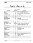

![Wi-Fiアクセス for ビジネス 設定マニュアル [PDF 0B]](http://vs1.manualzilla.com/store/data/006595538_2-472d88167ebf2e4f2c6c759ab1c0b4b9-150x150.png)