1
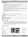
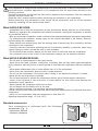
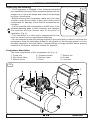
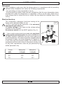
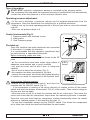
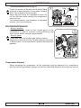
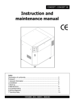
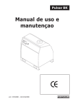
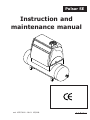
Pulsar SE
Instruction and
maintenance manual
cod. 197CC4100 - Ed.01 05/2008
ENGLISH
INTRODUCTION
Using the manual
This manual is an integral part of the compressor and should be kept for its whole
working life.
Keep this manual in a safe place to prevent it from being damaged.
If the compressor is sold to a third party, the instruction manual must be transferred to the
new owner, who will need to have the information it contains.
Read the manual carefully before putting the compressor into operation, and consult it
whenever you have any doubts about its operation.
The manual contains important safety information, describing the procedures for
performing particular operations that, if not complied with, could cause damage to persons
or to the equipment. You will also find information that will facilitate the use and
maintenance of the compressor.
Should this manual be lost, please request a duplicate copy.
The spare parts list is not an integral part of this manual since it is available at authorised
dealers’ offices only.
Symbols
The following symbols are used for especially important information:
Caution
Highlights precautions to be taken to ensure the safety of the operator and other persons
in the work area, and of the compressor itself.
Notes
Highlights procedures or precautions recommended to facilitate maintenance or to clarify
the most important instructions.
Specialised personnel
This symbol identifies operations that must only be performed by a specialised technician.
Technical assistance
For the maintenance of the compressor, use only original spare parts.
Non-original spare parts present potential risks that could cause damage to the
compressor or injury to people. In order to provide your with the most efficient service, and
for any request you may have, always indicate the model, type, and code number of your
compressor, which you can find on the cover page of the manual as well as on the
product identification plate on the compressor.
Product identification
Manufacturer data
TYPE
CODE
SERIAL N.
Air output (l/min) and (cfm)
Technical data:
voltage (V/ph/Hz)
Absorption (A)
Power (HP and kW)
Revolutions per minute (rpm)
1
2
3
4
5
CE Mark
Year of manufacture
Max. pressure
(bar and PSI)
Noise output -dB(A)
6
7
E / 3
Any other
homologations
ENGLISH
1. GENERAL INFORMATION
This compressor is designed and manufactured to be used exclusively to deliver compressed air for
handicraft and/or industrial applications in full compliance with the instructions provided in the
following sections.
Numerous pneumatic accessories and tools can be applied to the compressor. See the respective
manuals for their correct use.
Read this user’s manual carefully before performing any operation on the compressor.
Before performing any maintenance work, switch off the compressor and cut off the electrical
power by switching off the wall-mounted switch.
What SHOULD BE DONE:
• Understand how to stop the compressor at once and become familiar with the use of all controls.
• Before any operation the compressor tank should be emptied. Unplug the compressor to prevent
any accidental start-up.
• After any maintenance operation, make sure that all the disassembled parts are properly assembled.
• To guarantee safe operation, always carry out the checks described in the section “Start-up”
before starting the compressor.
• Keep children and animals away from the working area to prevent any injury caused by devices
connected to the compressor.
• Carefully read the instructions regarding the tool or accessory installed; in particular, when using
a paint spray gun make sure that the shop is well ventilated.
• For the three-phase models, always use the wall switch to start and stop the compressor.
• For continuous work in the vicinity of the compressor, always use ear protection devices.
What SHOULD NEVER BE DONE:
• Do not paint in closed spaces or near open flames.
• Never touch the head, cylinders, cooling fins, or delivery pipe, as they reach high temperatures
during operation and stay hot for a certain period of time after the compressor has been switched
off.
• Never place inflammable nylon or cloth objects near or on the compressor.
• Never move the compressor when the tank is under pressure.
• Do not use the compressor if the power cable is faulty or the electrical connection is unsafe.
• Never aim the air jet at people or animals.
• Do not allow anyone to operate the compressor without giving him/her proper instructions.
• Never hit the flywheel or fans with blunt or metal objects, as this could cause damage the
compressor during operation.
• Never operate the compressor without an air filter.
• Do not tamper with the safety valve or the tank.
• Never use the compressor in a potentially explosive atmosphere.
• Never connect the air outlet cock to a hose with a maximum capacity which is lower than that of the
compressor.
• Never run the compressor when the temperature is less than 0°C.
Operating temperature range: +5°C to +45°C.
Standard accessories
Your compressor is delivered with the following
accessories (Fig. 1):
• Instruction Manual
• vibration dampers
E / 4
1
1. GENERAL INFORMATION
Unpacking and handling
2
• The compressor is shipped to the customer protected
by a cardboard covering. Wear protective gloves and use
scissors to cut the outer straps and remove the package
by lifting it from the top.
• Before removing the compressor, make sure it is intact
(outside), open access doors (if any) and visually check
components for damage. Check that all accessories are
included.
• Lift the machine with a transpallet or forklift truck, fit the
vibration-damping pads in their housings, and transport
the machine with the utmost care to the place of
installation (Fig. 2).
• The connection to a tank and/or compressed air line
must be carried out by a specialised technician.
• You are advised to keep the packing material in the event that you need to re-locate the
compressor. Keep the packaging at least for the duration of the warranty period, so it can
be safely shipped to a service centre, if needed.When no longer needed, deliver packing
material to the special collection centres for disposal.
Compressor description
The main components of the compressor are (Fig. 3):
1. Pump unit
4. Pressure switch
2. Non-return valve
5. Delivery hose
3. Electric motor
6. Cover
7. Electric fan
8. Air tank
9. Line cock
3
E / 5
ENGLISH
2. INSTALLATION
Placement
Upon installation, make sure that the chosen place is in compliance with all prevailing
national safety standards and meets the following requirements:
• low percentage of dust suspended in the air,
• the shop must be suitably sized and well ventilated so that the room temperature never
exceeds 45°C when the compressor is in operation. If this is not the case, install one or
more exhaust fans to extract the hot air. Ideally, the fans should be installed close to the
ceiling.
Electrical hook-up
The compressor undergoes functional testing at the
factory and is delivered ready for use.
• Prior to performing any operation, it is extremely
important to make sure that:
the mains voltage is the same as the voltage rating
indicated on the CE plate,
the pressure switch is in the 0/OFF position (Fig. 4).
• Have a wall-mounted switch provided with plug fuses
(rating must be at least equal to the values indicated on
the table) installed it upstream from the control panel by
a skilled technician. The switch should be installed within
the operator’s reach (see wiring diagrams in Chapter 6).
In the event that the machine needs to be modified for
compliance with the rules in force in the user’s country or
for any other requirements, have the job performed by
skilled personnel only.
Power
(HP)
4
5,5
7,5
Absorption
V 230 (A)
14,7
16,6
22
Absorption
V 400 (A)
8,5
9,6
12,7
E / 6
4
3. START-UP
Type of operation
START-STOP operation: compressor starting is controlled by the pressure switch.
The compressor will stop when the maximum pressure is reached and it will automatically
re-start only when the pressure is at the minimum allowed value.
Operating pressure adjustment
• At the user’s discretion, a pressure reducer can be installed downstream from the
compressor. Have the distribution line configured by a qualified technician.
• Always look up the ideal operating pressure of the tool you wish to use in the relevant
manual.
• After use, set pressure back to 0.
Control instruments (Fig. 5)
5
1. Pressure switch with overload cut-out
2. Safety valve
3. Tank Pressure gauge
First start-up
Once the machine has been positioned and connected
to the mains, it is ready for operation.
It is recommended that this operation (operational test)
be performed by a specialised technician.
Before continuing, make sure that:
• the mains voltage is the same as that shown on the CE
plate
• all the connections have been made using cables of
adequate cross-section and in good condition
• the wall-mounted switch has fuses of adequate
capacity
• the oil level is above the minimum (Fig. 6)
• the machine has been connected to the tank.
• remove the rear panel, and check the flywheel direction
of rotation, an arrow it's impressed on the flywheel itself.
6
MAX
MIN
Carry out the following controls:
• Switch on the wall-mounted switch and start the
machine with the ON/OFF switch (Fig. 5).
• If the compressor is running in the wrong direction of rotation, switch off the master
switch and invert the phases at terminals L1-L2-L3 of the switch. Then restore voltage to
the line and start up again.
• Allow the motor to run for at least five minutes with the air cocks open. Then close the
cocks and check that the compressor stops when the maximum pressure is reached.
Open the cock and check that the compressor restarts automatically when the restart
pressure is reached (approx. 2 bar less than the max. P).
• To stop the compressor, always use the ON/OFF switch. This allows the compressed
air to drain from inside the head and facilitates the next restart.
E / 7
ENGLISH
4. MAINTENANCE
Before carrying out any maintenance operation:
Switch off the machine and the wall-mounted switch.
Bleed the air inside the compressor and/or tank.
Close the cock between compressor and tank.
Cabinet panels disassembly
The protection panels have to be removed to access the compressor.
Front and rear panels: unscrew the screws and remove the panels.
Upper panel: unscrew the screws and lift the panel, being careful not to jerk the fan
connection cables
Never operate the compressor with the protection panels removed.
AFTER THE FIRST 100 OPERATING HOURS
• Check that all screws are tightened, with special attention to head screws.
• Check that all piping connectors are tightened.
• Check that the terminals on all the power cables going to the control panel are tightened.
• Check for any dust inside the cabinet to determine whether the conditions in the shop
meet recommended requirements.
The compressor must be cleaned
EVERY 300 HOURS
• Suction filter cleaning (Fig. 7)
To access the filter, remove the cover situated on the righthand side of the body.
Then remove the air filter cover, extract the paper element
and blow it thoroughly with compressed air before refitting it.
Never operate the compressor without filter: foreign
bodies or dust could cause serious damage to the internal
components.
N.B. Every two oil changes, replace the filtering element.
7
A
MAX
EVERY 500 HOURSOGNI 500 ORE
• Oil change (Fig. 8)
• Remove the cap (A) from the filling mouth and unscrew
the plug (B) from the discharge cock; connect the hose
(C) (supplied) and open the cock, completely draining
the oil into a container.
• Disconnect the hose (C) and re-tighten the plug (B)
before filling with new oil.
• Top up and change the oil when the compressor is
warm.
Never mix different types of oil.
Do not disperse used oil in the environment: take it to the
proper disposal centre.
Recommended oil: SYNTENERGY
Re-position the cap (A) correctly before starting up the
compressor.
E / 8
MIN
B
oil
C
8
4. MAINTENANCE
• Drive belt tension check (Fig. 9)
Check the tension of the belt, which should have
a flexion of approximately 10 mm when a load of
30N / 3kg is applied at mid-length.
Adjust the belt using the adjustment screw (R)
on the left-hand side viewing the compressor
from the front.
To increase tension, turn clockwise; to decrease
tension, turn anti-clockwise.
9
3 Kg.
10 mm
R
vista posteriore - back side
ROUTINE MAINTENANCE
• Every 6 months
It is advisable to clean all the finned parts of the
compressor in order to maintain cooling efficiency and
thus ensure better machine performance.
• Every 2 years
Check and clean the suction and delivery valves.
Inspect the check valve A (Fig. 10) and replace if necessary.
In these cases it is recommend to replace the respective
gaskets.
10
Compressor disposal
When scrapping the compressor, all the materials must be disposed of in compliance
with the current regulations. Always contact the dedicated disposal and recycling centres
E / 9
ENGLISH
5. TROUBLE-SHOOTING
Problem
Cause
Remedy
Air leaking from the pressure Check valve leaking.
switch valve when the
compressor is stopped
Bleed air off the tank, remove the check value
cap and clean valve seat and sealing
element. Replace the sealing element if
necessary.
The compressor stops and Winding burnt.
cannot be restarted.
Call a specialised technician.
The compressor stops once Irregular operation or pressure Call a specialised technician.
the max. pressure has been switch broken.
reached and the safety valve
starts working.
The compressor does not Head gasket or valve broken. Stop the compressor immediately and call a
charge and causes overheating.
specialised technican.
The compressor is very noisy Seizure of the bearings.
and rattles.
Stop the compressor immediately and call a
specialised technican.
6. WIRING DIAGRAMS
Pulsar SE
Electric-fan
power
connection
A .........
B .........
C .........
...........
Electric motor
Pressure switch with ovl. cutout
Thermal relay 3-10 A (HP 4-5,5)
Thermal relay 3-16 A (HP 7,5)
E / 10
F1/F2 .. Fuse 5x20 1A
MC ...... Electric-fan
C ......... condenser 2 mF