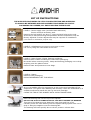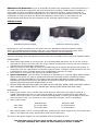
1
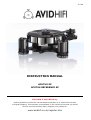
V 2.2E
INSTRUCTION MANUAL
ACUTUS SP
ACUTUS REFERENCE SP
Extended 5-Year Warranty
AVID is pleased to extend the normal warranty duration to 5-Years from the date
of original shipping. This warranty is transferable in the unlikely event that you would
sell this unit onto another party. Register your product at:
www.avidhifi.co.uk/register.htm
Table of Contents
Section
Page
Preface
3
Introduction
3
Warnings
3
Packing
3
Parts Checklist
3
Set-up Instructions and User Guidance
4
Power Supply
7
Servicing
8
Cleaning
8
Warranty-Terms and Conditions
8
Specifications
9
WARNING
YOU MUST ALWAYS REMOVE THE PLATTER AND BEARING
AND USE THE TRANSIT PACKAGING WHEN YOU TRANSPORT
YOUR TURNTABLE OR YOU MAY DAMAGE THE BEARING
DON’T PUT IT ON THE BACK SEAT OF YOUR CAR—YOU’LL BREAK IT
PREFACE
Please take time to read this Instruction Manual before unpacking your Acutus SP Turntable.
This product is a precision engineered machine and whilst damage is unlikely with careful handling,
the sheer mass of some of the parts could lead to damage of less robust parts within its design.
Some of these parts have been excluded from the warranty.
<TAKE CARE AND READ THIS MANUAL>
INTRODUCTION
Acutus is an Audio Analogue Turntable manufactured to extreme limits of precision, design and
detail. There are many unique and novel features in this product and its design allows you to install
the pick-up arm and cartridge of your choice. With correct ancillary equipment it will take your
listening pleasure to new levels of excellence.
The Acutus has two main components, that being the turntable itself, made up of 6 parts and the
external power supply.
Whilst it shares some features found in other turntables, it has been designed without compromise
not trying to emulate or improve existing designs but redefine the whole thinking behind turntable
design.
We hope that you enjoy this turntable for many years!
WARNINGS
1. To prevent fire or electric shocks do not expose either the power supply or motor assembly to
rain or moisture.
2. The Main Bearing contains a Sapphire Cup Jewel and this can be damaged if proper care is not
taken (see set-up and warranty) and this will affect or stop your turntable working correctly.
3. The Platter surface may be cleaned with mild soapy water without harm but take care not to
scratch its surface.
4. The Power Supply contains voltages, which can cause serious injury or death as there are no
user serviceable parts there is no reason to open it. In situations of failure return to an
approved dealer or service agent. There are calibrated components inside and altering their
settings will affect the performance and void the warranty.
5. The Motor is an individually hand crafted component and must under no circumstances be
opened or adjusted. If you experience what you think to be a problem consult an approved
dealer, service agent or AVID direct.
PACKAGING
Save all the packing in a dry place away from fire hazard. The Acutus Turntable is a precision
instrument and the packaging has been especially designed so that all component parts are safe
during transportation.
You should not have occasion to return your unit to us, but if you need to, the unit must be
shipped in its original packaging to keep it from damage. In the event of the packing being lost or
damaged further packing can be provided at cost.
Do not transport the turntable assembled. This may cause damage and void the warranty.
PARTS CHECKLIST
The packing has been designed to eliminate parts being missed, however if something is found to
be amiss please contact your dealer.
Instruction Manual
Platter
Sub-Chassis
Clamp
Main Chassis
4mm Tungsten Carbide Ball
1
1
1
1
1
1
Drive Belt
Main Bearing
Motor Assembly
Power Supply
2
1
1
1
Motor Restraining Band
Suspension Lateral O-ring
Wrench Key Size 3mm A/F
Belt Pin
Power Cord
1
3
1
1
1
SET UP INSTRUCTIONS
THE SUPPLIED PACKAGING IS VITAL FOR PROTECTION AND SHIPPING.
IT SHOULD BE RETAINED AND REPLACEMENT PACKAGING IS COSTLY.
PACKAGING IS LAYERED, ALL PARTS HAVING THEIR PLACE.
LAYER 1: Power supply case (excluded with Reference)
Power cord and accessory pack.
Remove the PSU and lift out layer 1 using the hand holes at the side.
Arms can be mounted during transportation and the suspension may be
factory adjusted. Further adjustment may be required on installation.
(Arm shown for illustration purpose only)
LAYER 2: Subchassis and optional arm/cartridge if fitted.
Lift out by using the hand holes at the side.
LAYER 3: Main Chassis, Clamp, Bearing and Motor.
Remove Main Chassis including the white foam packaging.
Be careful when removing motor, clamp and bearing packaging not to drop
anything onto the platter below.
Remove foam and protective cover bags.
LAYER 4: Platter.
Remove from packaging.
PLEASE REMEMBER THAT THIS HEAVY.
All our turntables offer the opportunity to set up the arm/cartridge off the
suspension. This gives more stability and accuracy. Place the subchassis on a
suitable surface and install the pick up arm and cartridge.
CLEAN THE TOP OF THE SPINDLE WITH CLEAN TISSUE PAPER.
Place the bearing ball into the top of the spindle.
DO NOT USE GLUE OR LUBRICATION AS THIS WILL DAMAGE THE BEARING
This part of the bearing must always be kept clean and free of oil.
Carefully lower the main bearing onto the spindle taking special care not to
drop or bang the sapphire onto the bearing ball.
The bearing will lower quickly due to the air pressure release hole.
Slowly lower the platter onto the main bearing.
USE EXTREME CARE Not to drop or impact onto the bearing as this could
damage the sapphire bearing.
To remove the platter hold at edges and gently rock while lifting to release
from main bearing taking care not to lift the bearing itself.
After fitting the record and clamp (see clamping on next page) use
alignment tools to correctly set up your pick-up arm and cartridge.
Once done it can be carefully disassembled for fitting onto the main chassis
and suspension.
Ideally the main chassis will be placed onto a level surface.
The feet can be adjusted for fine levelling, however if this is too excessive
the motor will not be square to the chassis and the drive belt may not run
true to the platter.
Fit the motor into the cut out in the main chassis.
There is a lower rubber O-ring on the motor and this locates into a groove on
the side of the chassis.
The motor foot can be adjusted to obtain the correct height.
Once in position the motor can be secured with the supplied rubber O-ring.
Stretch around the motor, fixing each end to the bolt heads on the main
chassis side.
Carefully fit the subchassis to the main chassis, locating the subchassis legs
into the suspension cups at the spring base.
Take care that the subchassis does not tip off due to the weight of the fitted
arm. You can apply some downwards pressure to the subchassis making
sure the legs are fully inserted.
Take care the bearing ball does not fall out when removing subchassis.
Refit the main bearing as previously instructed, taking special care of the
sapphire bearing.
Platter and drive belt fitting.
Place the platter top face down. Locate a small hole on the edge rim of the
platter. Once found, insert the belt fitting pin.
Always make sure you have clean hands when handling the drive belts and
before fitting the belt it is a good practice to clean the platter drive hub and
motor drive pulley. Isopropyl alcohol cleaner would be suitable.
Stretch the two belts over the hub onto the fitting pin one at a time making
sure they are not twisted together.
Carefully fit the platter to the bearing, making sure the location of the
fitting pin is between the motor and the front left suspension housing.
Gently lift the platter edge exposing the motor pulley.
Rotate the platter and dress the belts onto the drive pulley.
Once done remove the fitting pin. Manually rotate the platter by hand to
align the drive belt correctly.
Fit the lateral suspension O-rings to each suspension tower.
Stretch the O-ring so it fits between the platter and the subchassis post,
making sure its correctly fitted into the location groove and not caught
between the post and platter wall.
Stretch over the two main chassis posts.
Take care when doing this near your cartridge.
WARNINGS AND USING THE CLAMP.
The female part of the clamp is made from stainless steel and the male
bearing part is brass. You will need to take care not to strip or cross thread
the clamp onto the main bearing.
Before fitting the clamp ALWAYS WIND THE MIDDLE COG UP to the top
cog. If this is not done you will eventually strip the brass thread.
Holding the underside of the platter with fingers and thumb on record,
place the clamp onto the spindle. This gives you control of the platter
whilst not leaving unsightly fingerprints on the platter wall.
Using the top cog, screw the record down tightly. Then using the middle
cog screw down until the record is flat and in full contact with the platter.
To release the clamp, hold the platter in the same way and grab the whole
clamp, twisting and unscrewing off.
Then ALWAYS UNWIND THE MIDDLE COG UP for refitting.
SUSPENSION SET UP AND ADJUSTMENT.
The turntable platter should be approximately level; however THIS IS NOT
CRITICAL and other factors are more important to obtaining best
performance. Once set up the platter, complete with record and clamp,
should bounce with a smooth piston type movement, the drive belt running
without any movement. You can easily see this by looking underneath the
platter whilst it’s running. As a starting point, level all the suspension posts
with the main chassis posts. This is done by inserting the supplied Allen
wrench into the hole on the subchassis suspension post. Push down to
engage the wrench and turn clockwise to lower or anticlockwise to raise
the suspension point.
Make further adjustments as necessary to obtain the correct movement.
DRESSING THE ARM LEAD Is just as important as setting the suspension. Incorrectly done or if
the lead is too stiff the suspension will be prevented from working. Leads should be looped in a
circle under the arm and clamped behind the rear suspension housing. Check movement of
suspension is working correctly. Depending on your set up it may be possible to leave the lead
unattached so long as it does not affect the suspension. Thick heavy or stiff leads are not
recommended and should not be necessary as the cartridge output signal is so small.
POWER SUPPLY
Standard SP Power Supply
Reference SP Power Supply
Depending on your purchase you will either have the Standard or Reference power supply.
These are purpose designed “state-of-the-art” units designed for the powerful motor used.
Your warranty becomes void should anybody tamper with the internal settings
Controls are simple and well labeled, however this will also explain how to adjust the platter speed.
FRONT PANEL;
a. When ON a light shows on the front left. It is recommended that when not in use the unit be
switched off, as this will extend the life of the internal components. There is no sonic benefit in
leaving the unit permanently switched on.
b. When the PSU is switch ON the speed is automatically set to 33rpm and shows with a light. To
set 45rpm push the right button and another light will shine. If 45rpm is selected when the unit
is switched off, when re-powered the unit automatically switches to 33rpm.
c. PLAY button in the center also provides the STOP function.
d. Speed adjustment. You will need a strobe disc or alternative to correctly adjust platter speed.
Select which speed you wish to adjust and press and hold both 33rpm and 45rpm buttons
together until the light flashes. The flashing light indicates adjustment mode is selected.
Pressing the 33rpm button slows the platter and 45rpm increases the speed. Once correct
speed is achieved press both buttons again to lock.
e. DO NOT SEE HOW FAST OR SLOW YOU CAN GO AS THIS WILL OVER-LOAD THE SUPPLY AND IT
WILL POSSIBLY BECOME FAULTY. ABUSE WILL BE EXCLUDED FROM OUR WATTANTY.
REAR PANEL:
a. Mains input socket. This is an IEC type socket and you should use the cable provided or a
suitable alternative fused at no more than 5 AMPS. It is worth experimenting with different
cables, which can make or not make a difference depending on where your supply is from and
even the time of day. (Try listening to your system after 2.00am, you’ll be surprised.)
b. Fuse in IEC socket.
220~250v
100~120v
Standard PSU
T1.0A slow blow
T2.0A slow blow
Reference PSU
T6.3A slow blow
T10A slow blow
c. PSU output socket. This is a locking DIN type, matching the motor supply lead. Do not alter this
cable, it will affect the motor performance and void the warranty.
The feet on the power supply are not adjustable and not designed to turn.
The standard supply will get warm as the rear panel is used as a heat sink.
If it gets extremely hot, switch off and contact your dealer or AVID.
SERVICING
Because of the careful design of this product general servicing is not required.
The only two things that will need attention will be:
1. Drive Belt, which we suggest be replaced annually.
2. Main Bearing Lubrication. This should be done by AVID after approximately 10 years service.
CLEANING
To maintain the visual appearance of Acutus, occasionally dust the surfaces with a normal duster no need for any sprays or polishes.
Fingerprints, greasy marks or similar smudges can be removed with a damp cloth with mild soapy
water or isopropyl alcohol cleaner.
DO NOT ATTEMPT TO CLEAN THE DRIVE BELT WITH ANYTHING.
IF DIRTY OR GREASY IT WILL PROBABLY NEED REPLACING.
Never use cleaners containing abrasives, as this will damage the surface.
Warranty Statement
UK Residents
AVID HIFI Limited products are warranted against defects in materials and workmanship for a
period of two years from the original date of purchase, or no later than three years from the date
of shipment to an authorized AVID agent, which ever comes first, extending to five years subject to
the product owner having submitted the Registration form (www.avidhifi.co.uk/register.htm).
Also the following conditions being observed.
•
•
•
•
•
•
•
•
•
•
•
•
•
•
The product must have been purchased through an authorized AVID dealer
This warranty is in favour of the original purchaser only, except where...
Warranties are transferable to subsequent owners provided the new owner completes the
product registration form. Warranty obligation is passed from dealer to manufacturer.
During the warranty period, AVID will repair, or replace any defects in material or
workmanship, without charge for parts or labour.
Should product need to be returned a written description of the defect and a photocopy of
the original purchase receipt must accompany it. Receipts must show the model, serial
number, date of purchase, name and address of purchaser and authorized dealer and the
price paid.
Returned product must be packed in the original packing and returned to AVID or original
dealer by the customer at his/her expense. AVID will pay return freight of its choice.
The warranty is void if the product has been used or handled other than in accordance with
the instruction manual supplied, abused or misused, damage by accident or neglect or in
being transported, or the defect is due to the product being repaired or tampered with by
anyone other than AVID or an dealer with prior authorization.
The warranty is void if the product serial number has been removed, altered or made
illegible.
The warranty is void if the product has been taken out of the country of purchase.
Specific parts excluded from this warranty include: sapphire thrust bearing, drive belts and
O-rings.
These items have no warranty, however replacements may be issued by AVID at our
discretion.
AVID shall not be held liable for incidental or consequential damages of any kind arising
from the sale or use of its products.
The warranty applies to ex-demonstration product, using the date of manufacture as
purchase date.
Where the product is sold under a consumer transaction (as defined by the Sale of Goods
Act 1979) the statutory rights of the purchaser are not affected by this warranty.
Products are sold on the basis of specifications applicable at the time of sale. AVID shall
have no obligation to modify or to update products once sold.
Outside UK
•
•
•
•
•
•
•
AVID has formal distribution in many countries throughout the world. In each country the
AVID importer has contractually accepted the responsibility for the product warranty.
Warranty should normally be obtained from the importing agent or distributor from whom
you obtained your product. In the unlikely event of service required beyond the capability of
the importer, AVID will, of course, back up the warranty.
Where product has been either supplied directly or there is no current distributor, AVID
accepts responsibility for the warranty period.
Returned product must be packed in the original packing and returned to AVID by the
customer at his/her expense. AVID will pay return freight of its choice.
The warranty is only valid in the country of purchase.
Products outside there original destination requires that units with remaining warranty be
returned to the country of purchase for the warranty to be valid. Customer is responsible for
freight both ways and all associated import and export charges.
Foreign distributors are not required to provide warranty service, repair or change AC mains
voltage on units that they did not originally import and sell.
Foreign distributors may at their discretion offer service for a fee.
MISCELLANEOUS. ANY IMPLIED WARRANTIES RELATING TO THE ABOVE PRODUCT SHALL BE
LIMITED TO THE DURATION OF THIS WARRANTY. THE WARRENTY DOES NOT EXTEND TO ANY
INCIDENTAL OR CONSEQUENTIAL COSTS OR DAMAGES TO THE PURCHASER.
WARRANTOR. Inquiries regarding the Limited Warranty may be sent to the following address:
AVID HIFI Limited. Bicton Industrial Park, Kimbolton, Huntingdon. PE28 0LW ENGLAND
SPECIFICATIONS
Standard Acutus
DRIVE
SPEEDS
PLATTER MASS
BEARING
THRUST POINT
SUSPENSION
TONEARMS
MOTOR
POWER SUPPLY
VOLTAGE INPUT
DIMENSIONS (overall)
(footprint)
(PSU)
NET WEIGHT
PACKAGING
SHIPPING WEIGHT
Reference Acutus
BELT
33 and 45 rpm
10 Kg
Inverted stainless steel
Tungsten carbide/Sapphire
3 point, springs in vertical, o-rings in lateral frequency
Std. cut for SME (adapters to order)
Hand built 24v 140mNm ac synchronous
Separate control unit
100-240vac 50/60Hz 20 watts
100-240vac 50/60Hz 300 watts
max. (depending on region)
max. (depending on region)
460 x 400 x 210mm (WxDxH)
410 x 360mm (WxD)
250 x 215 x 95mm (WxDxH)
415 x 350 x 140mm (WxDxH)
19.0Kg (42lb) turntable only
3.5Kg (8lb) psu only
20.1Kg (45lb) psu only
550 x 500 x 550mm (WxDxH)
550 x 500 x 550mm (WxDxH)
710 x 490 x 270mm (WxDxH)
30.0Kg (66lb)
55.0Kg (122lb)
AVID reserves the right to improve or change its products without notice at any time.
EC Declaration of Conformity
17 July 2002
We declare that our Acutus, Sequel and Volvere PSU conform to directives and harmonized international standards
LVD (73/23/EEC) Low voltage directive
EMC (89/36/EEC) Electromagnetic conformity
BS EN 60065: 1994 Safety requirements for mains operated electronic and related apparatus for household and similar use
CENELEC HD21/22
EN 55020: 1988
EN 55013: 1990
C. Mas
Flexible cables and cords
Electromagnetic Immunity
Electromagnetic Emissions
Director
AVID HIFI Limited